

Page 1
ISU 140/160 KD (c/w SAT-2 Controller)
30 mm
MAXIMUM
MOUNTING ROD
MOUNTING
BRACKET
ISU 90: 1203 mm
ISU 140/160: 1803 mm
OPTIONAL
WALL
MOUNTING
(RECESSED)
UNDERCEILING
MOUNTING
Underceiling/Console
Split System Indoor Units
GENERAL
The ISU Underceiling Indoor Units are
designed to be coupled with the OSA
outdoor units and controlled by the SAT-2
room temperature controller. Units must be
installed in accordance with all national and
local safety codes.
Combinations
One ISU 140KD with one OSA 140RKTH
One ISU 160KD with one OSA 156RKSH
One ISU 160KD with one OSA 156RKTH
UNPACKING UNITS
The OSA outdoor unit and ISU indoor unit
are cartoned separately. Unpack each item
carefully. Examine for transit damage.
ISU UNIT
Components
The ISU carton includes:
1. ISU indoor unit.
2. SAT-2 Wall Control (shipped inside
unit behind filter panel)
3. Insulated condensate drain extension kit.
4. Right-angled suction pipe extension
c/w lock nut and teflon seal.
INSTALLATION
Positioning & Mounting
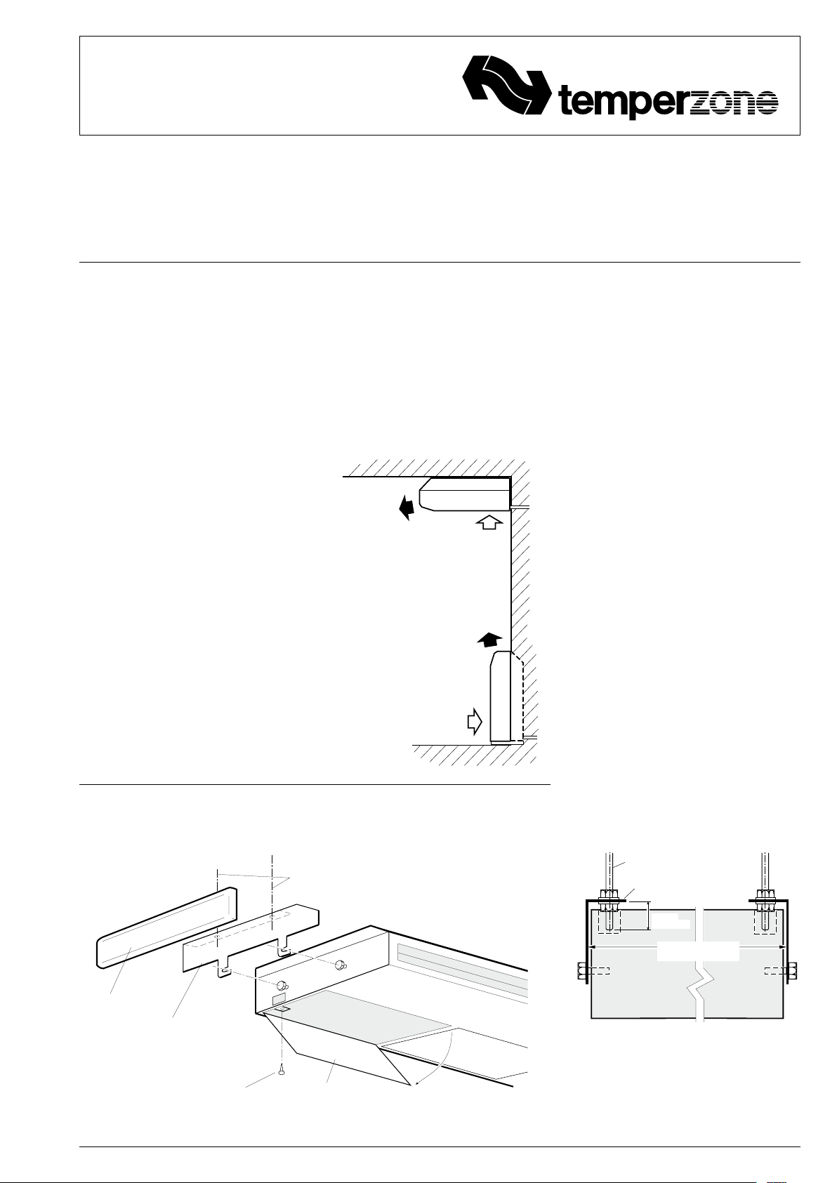
The ISU is designed to be installed :
a. suspended horizontally beneath a level
or sloping ceiling, or
b. floor or wall mounted (i.e. vertically).
Note: For an extra low profile the unit can
be recessed into the ceiling (or wall).
Fig. 1 Mounting Options
Installation &
Maintenance
Preparation
Prior to mounting the ISU the mounting
brackets must be detached from each end
of the unit.
1. Open the end filter panel and locate the
screw securing the unit endcaps (refer
figure 2).
2. Remove the endcap securing screw and
retain.
3. Remove the endcap by first sliding
it forward approx. 20 mm, then pull
outwards away from end of the unit.
4. Release each mounting bracket from
behind the two bolts securing them to the
unit.
5. Remove the floor mounting base from
the back of the ISU if when ceiling
mounted it is required to fit flush to the
wall.
Underceiling Mounting
Locate the ISU near a wall to take full
advantage of the long supply air throw and
to hide the condensate drain pipe (and other
connections) exiting at the rear of the unit.
Refrigeration and wiring connections are
via the top or the rear access holes. A rightangled suction pipe extension is supplied to
facilitate top exit.
Fig. 2 Mounting Bracket Detachment
VIEWED FROM BELOW
MOUNTING ROD CENTRES
ENDCAP
MOUNTING
BRACKET
SCREW SECURING
ENDCAP
HINGED DOWN
FILTER PANEL
Underceiling Installation
1. If an extra low profile installation is
preferred, first cut the required ceiling
aperture.
2. Install four M8 threaded hanging rods (not
supplied) to protrude no more than 30 mm
below the level of the mounting bracket
flange (refer figure 3).
Fig. 3 Mounting Detail
3. Thread on and tighten the lower washer
and locknut sets (not supplied) to secure
the left and right mounting brackets.
Note: Mounting bracket flanges face
inwards.
4. Adjust distance between mounting
brackets to match dimensions in figure 3.
Page 2

5. Lift the unit to the mounting brackets
locating the two protruding bolts, at each
end of the unit, securely into the two slots
provided in each mounting bracket, then
tighten bolts to secure the ISU unit.
6. Check that the secured ISU is installed
level to facilitate condensate drainage.
7. Complete all refrigeration piping
connections (refer 'Indoor-Outdoor Unit
Connections').
8. Fit the insulated condensate drain
extension, orientated so that the drain
vent tube is at the highest point in the
condensate line.
9. After completing all piping connections
replace the ISU unit's left and right
endcaps as follows:
a. Place each endcap slightly forward of
the appropriate end of the unit,
b. Compress the endcap at its centre
and slide back hooking the endcaps
hook under the 'U' shaped bracket on
the unit and into position .
c. Secure each with the screws removed
earlier from behind the filter panels.
Wall / Floor Installation
Vertically mounted, the refrigeration and
wiring connections can be made through the
back or base of the unit.
1. Measure and cut wall recess, if required.
2. Secure the mounting brackets to the
wall using fastenings suitable for the wall
construction and weight of the ISU unit.
(Note: Mounting bracket flanges to face
inwards.)
3. Refer to 'Underceiling Installation'
instructions, steps 4 to 9 above, to
complete vertically mounted installation.
INDOOR-OUTDOOR UNIT
CONNECTIONS
Refer to the relevant OSA Outdoor Unit
'Installation & Maintenance' pamphlet for
piping instructions. For wiring connections,
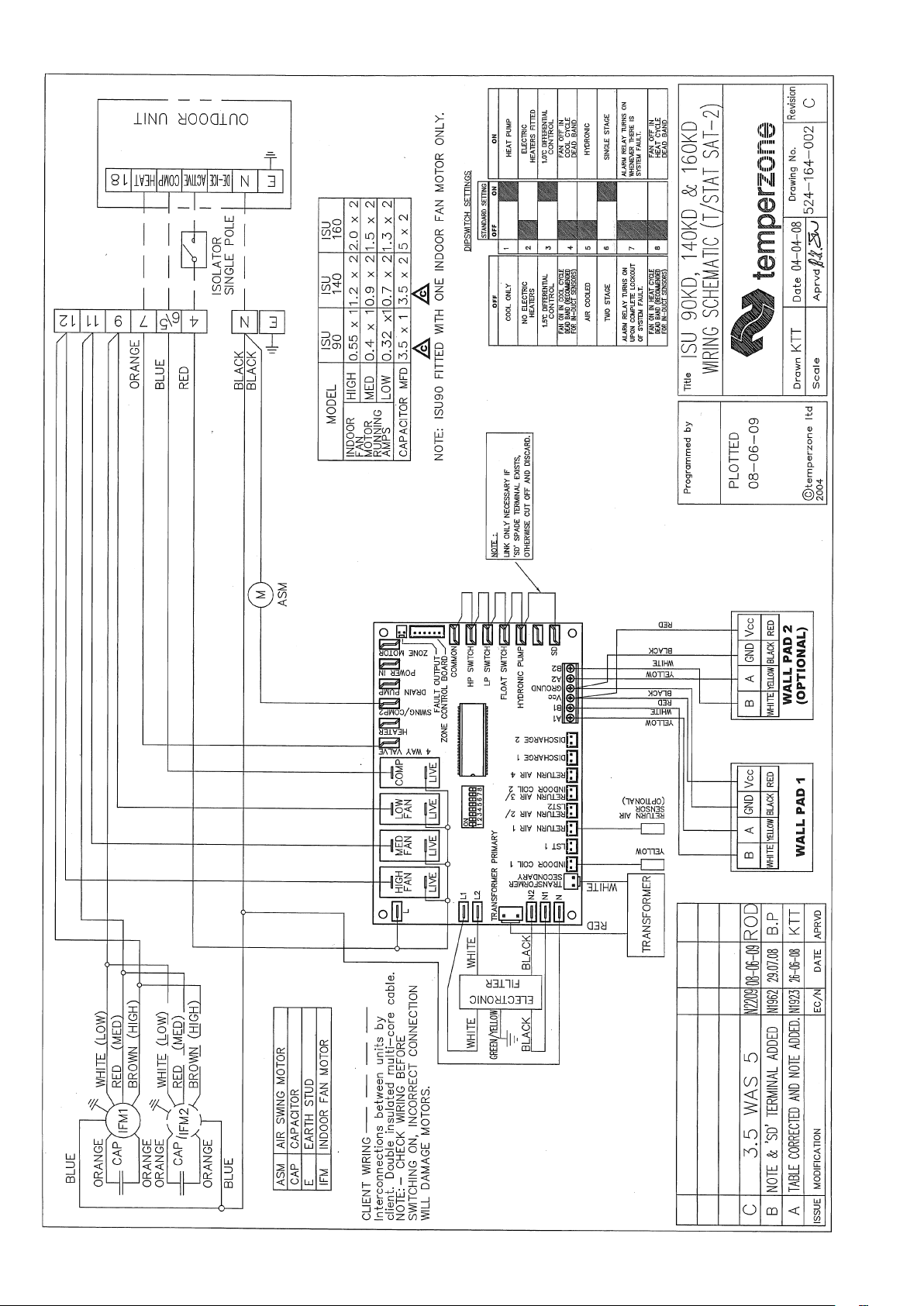
refer to the Outdoor Unit wiring diagram in
conjunction with the ISU wiring diagram on
this pamphlet.
REFRIGERATION PIPING
The ISU Underceiling is shipped from the
factory with a holding charge of dry nitrogen.
Refer to the Outdoor Unit 'Installation &
Maintenance' pamphlet for evacuation
procedure.
ISU 140, 160 refrig. line connections are:
Liquid: 13 mm OD (1/2") flare nut
Gas: 22 mm OD (7/8") sweat
Separation Limits
Maximum Pipe Length: Up to 30 m total
Indoor Unit above Outdoor Unit : 18 m
Outdoor Unit above Indoor Unit : 18 m
For line lengths in excess of the above,
contact the manufacturer's nearest sales
office for additional piping requirements.
CONDENSATE DRAIN
Connect a 19 mm ID drain pipe (not
supplied) to the ISU's drain connection.
Maintain a downwards slope of at least
1 in 50 (20 mm/m) along the drain line. No
‘U’ trap is necessary.
Insulation of the drain pipes is
recommended especially in high humidity
environments.
Note: The unit has a right angled drain tray
to allow for wall or ceiling installation.
ELECTRICAL WIRING
The electrical supply required (via the
Outdoor Unit) is specified on the Outdoor
Unit's wiring diagram.
Electrical work must be carried out by a
qualified electrician in accordance with local
supply authority regulations and the wiring
diagram.
Note: The SAT-2 Controller automatically
switches the indoor fan off during de-ice,
therefore no additional wiring is required to
achieve this result.
SAT-2 CONTROLLER
The following components are supplied
loose inside the ISU electrical box:
1. SAT-2 Wall Control plaque, including wall
mounting plate.
2. 10 m interface lead (electrical box-toplaque).
3. User's Operating Instructions booklet.
4. Lithium CR2032 battery (3V).
Optional
1. Remote return air sensor (in box).
2. Remote return air temperature sensor
lead; 1.5, 6, 12 or 25 m.
3. 20 m extended interface lead
(electrical box-to-plaque).
4. ISU/ISD indoor unit–to–OSA outdoor
unit interconnecting lead;
12.5 m or 25 m; 7 core.
5. Infra red remote control.
6. Additional SAT-2 Wall Control plaque.
Installation
The SAT-2 Controller PCB is supplied preinstalled in the ISU unit's electrical box.
1. Isolate the ISU unit from power supply,
then remove electrical box cover.
2. Remove the items supplied loose in the
electrical box.
3. Remove the Wall Control's interface
lead from its box and connect the bare
wired end of the interface lead to the
terminal block on the SAT-2 Controller
board (refer wiring diagram). Trace the
remaining length of the lead to the Wall
Control's intended location.
4. Remove the Wall Control's backing plate
by using a small screw driver to remove
the single screw at the bottom edge of
the plaque.
5. Install the Lithium battery, supplied loose,
positive (+) side up in the Wall Control's
battery holder.
6. Check the wall where the Wall Control
plaque is to be located is flat before
fastening the wall mounting plate.
Alternatively, the mounting plate can
be screwed to a standard wall socket
mounted horizontally.
Note: Use low profile (mush) headed
screws to prevent contact with the PCB
board. Fixing the plate to a distorted
surface may damage the control.
7. Drill hole in wall to allow cable entry.
8. Connect the interface lead's lugs to the
Wall Control board as per the wiring
diagram overleaf.
9. Ensure the interface lead is run
separately and away from main
power supply wires, including the
interconnecting cable. When installing
cabling, trim any excess length to suit
your location.
10. Fill around the interface lead with foam
or cover hole with PVC tape to prevent
draft from wall cavity affecting control
operation. Do not use aluminium duct tape.
11. Secure the Wall Control body to the
mounting plate by replacing the locking
screw removed earlier.
12.Replace the ISU electrical box cover.
Remote Air Temperature Sensor/s
(option)
The air temperature sensor is by default
located in the Wall plaque. Optional remote
air temperature sensors are available
so that the measurement of the room
temperature can be taken away from the
wall plaque, eg. elsewhere in the room or in
the return air duct.
Remote sensor's can be plugged directly
into the Controller board (PCB). This
board accepts up to four sensors which
are designated as 'zones' one to four. The
first return air sensor will automatically
replace the Wall Control sensor and should
be located in the same room as the Wall
Control. The Controller will always use the
average of the zones selected. Refer to the
separate installation instructions supplied
with the PCB for further details.
Ensure all remote sensor wires are run
separately and away from main power
supply wires, including the interconnecting
cable.
COMMISSIONING
Indoor Unit
1. Check that the thermostat is
correctly wired and set at the desired
temperature.
2. Check that the air filter is clean.
3. Check that the fan runs freely without
vibration.
4. Check condensate drain for free
drainage.
5. Refer to Outdoor Unit Installation &
Maintenance instructions and
Wall Thermostat User's Operating
Instructions to complete the start-up
and commissioning procedure for the
complete air conditioning system.
6. Run the motorised louvre to check
up/down air distribution. Use the switch
to set up/down louvre in fixed position,
if required. Do not try to set up/down
louvre manually.
7. With the motorised louvre switched off,
manually adjust the left/right louvre to
throw the air in the required direction.
8. Demonstrate the SAT-2 Wall Thermostat
to the owner/user, after having first
thoroughly familiarised yourself with the
User's Operating Instructions. These
instructions to remain with the owner/
user.
Page 3
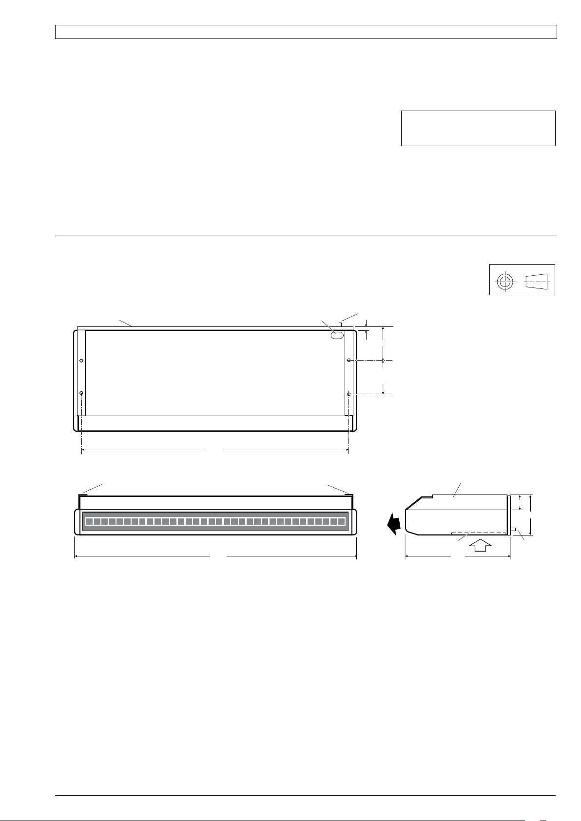
685
275
MOUNTING
CENTRE
170
MOUNTING
BRACKET
MOUNTING
BRACKET
DRAIN EXIT POSITION
& STANDARD REFRIG.
PIPE EXIT
FLOOR MOUNTING BASE
(REMOVABLE)
HINGE DOWN
FILTERS
ALTERNATIVE
REFRIGERATION
PIPE EXIT
DRAIN
19 OD
MOUNTING
BRACKET
1760
HANGING CENTRES
35
1860
100
265
PROJECTION
MAINTENANCE
Weekly For First Four Weeks
1. Check air filter; vacuum clean as
necessary.
2. Check condensate drains for free
drainage.
Monthly
Check air filter; vacuum clean as necessary.
Six Monthly
1. Check condensate drain for free
drainage.
2. Check the tightness of the fan.
3. Check that fan motor is free running.
4. Check tightness of electrical connections.
5. Check air supply at louvre.
WARNING
This unit is designed for use ONLY with
the refrigerant HCFC -410A. The use of
other refrigerants is NOT authorised or
approved by the manufacturer and may
cause operational problems such as poor
performance and efficiency, loss of capacity,
degradation of materials and refrigerant
leaks.
The use of flammable or explosive
materials as a refrigerant creates the
additional risks of fire and explosion
which may result in property damage,
personal injury or death.
NOTE
The manufacturer reserves the right to
change specifications at any time without
notice or obligation. Certified dimensions
available on request.
This pamphlet replaces the previous
issue no.s 3137 dated 06/09.
OSA 156 replaces OSA 160.
DIMENSIONS (mm)
Fig. 5 ISU 140, 160
Not to Scale
Indoor Units
Net Weight:
ISU 140 74 kg
ISU 160 74 kg
Page 4
11/10 Pamphlet No. 3518 © temperzone limited 2010
 Loading...