

Page 1
ISF 300K, 450K
PROJECTION
IT-Data Centre
Computer Room Indoor Units
GENERAL
These ISD indoor units are designed to be
coupled with their respective OSA outdoor
units. Units must be installed in accordance
with all national and local safety codes.
Combinations
One ISF 300K with three OSA 110RKTH
One ISF 300K with one OSA 330RKTV
One ISF 450K with three OSA 160RKTHG
One ISF 450K with one OSA 460RKTB
Optional
1. Remote return air sensor c/w 5m lead
and no case.
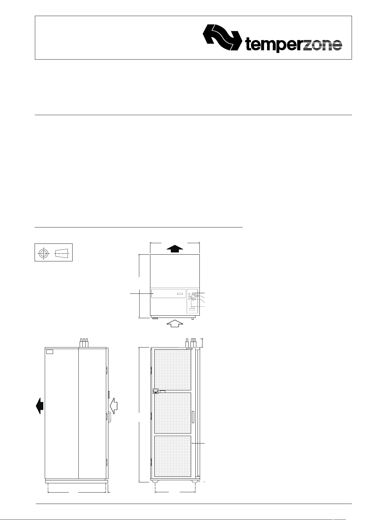
Fig.1 Dimensions (mm)
Not to Scale
Net Weight:
ISF 300K 200 kg
ISF 450K 250 kg
Electrical and Control
Connections
2. Remote return air sensor c/w case.
3. Remote return air temperature sensor
lead; 1.5, 6, 12 or 25 m.
4. 20 m extended interface lead
(electrical box-to-plaque).
5. ISF indoor unit–to–OSA outdoor
unit interconnecting power lead;
12.5 m or 25 m; 7 core.
INSTALLATION
Positioning & Mounting
The unit is dsigned for hot isle/cold isle type
computer room applications.
Provide sufficient clearance at the rear to
access the filters.
ISF 300K = 600
ISF 450K = 800
1028.5
Three Systems:
Middle Coil Connection
Top Coil Connection
Bottom Coil Connection
Condensate Drain 9.5 OD
Liquid 10mm OD
Gas 19mm OD
Installation &
Maintenance
Condensate Drain
The unit has three internal condensate drain
trays which are connected by drain tubes
to the lower tray, then into a sump. Water is
then removed, via a condensate lift-pump,
out the top of the unit.
It is essential that the drainage system
for the evaporator is checked by pouring
water in the top drain tray and seeing that it
discharges at the end of the drain and does
not overflow the drain trays.
INDOOR-OUTDOOR UNIT CONNECTIONS
Refer to the relevant OSA Outdoor Unit
'Installation & Maintenance' pamphlet for
piping instructions. For wiring connections,
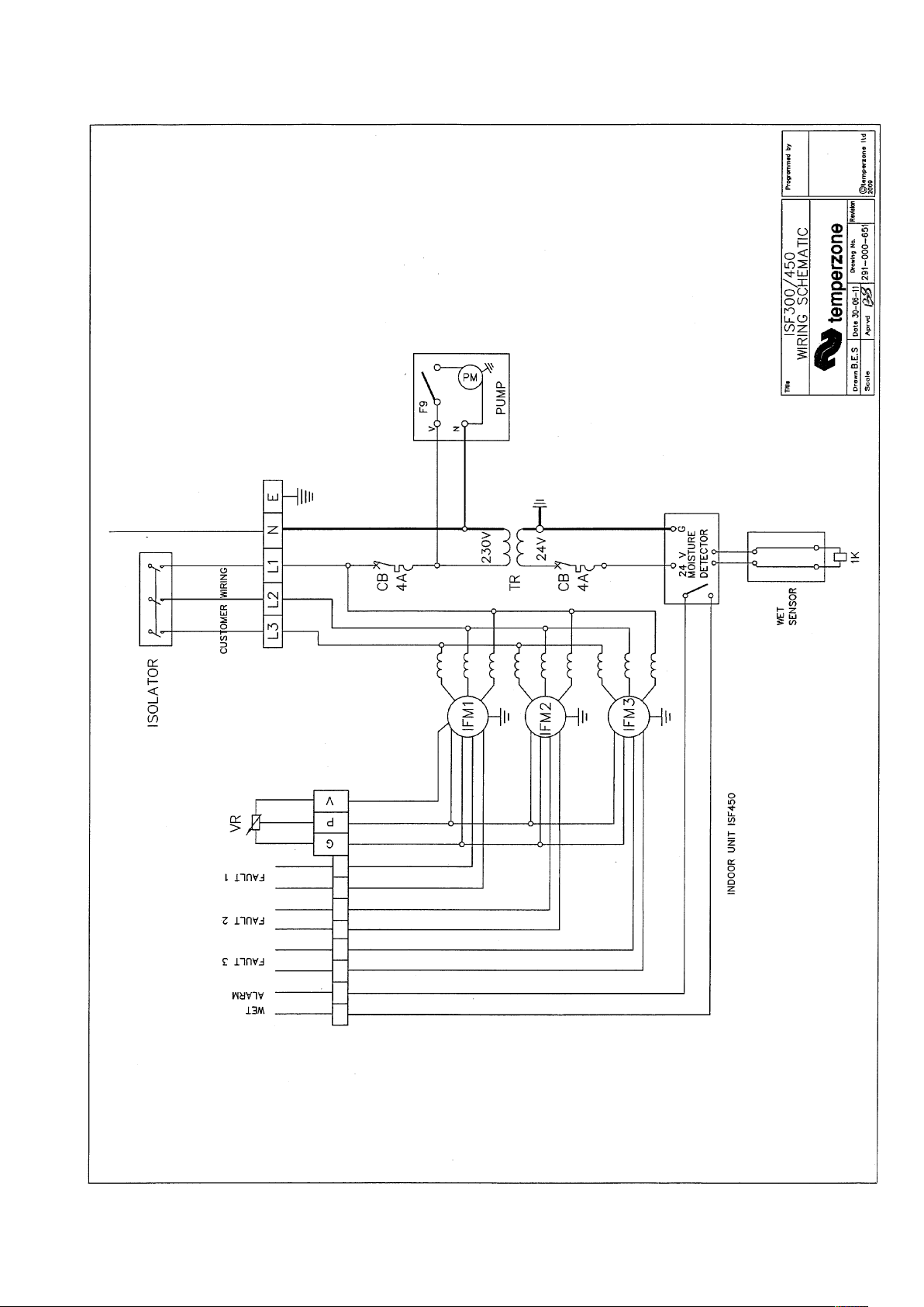
refer to the Outdoor Unit wiring diagram.
REFRIGERATION PIPING
Pipe Connection Sizes & Type
Liquid : 10 mm OD (3/8") sweat
Suction : 19 mm OD (3/4") sweat
The ISF is shipped from the factory with
a pressurised holding charge of nitrogen.
Immediately before removing any brazed
pipe connection's seal, reduce holding
charge to atmospheric pressure.
Warning: failure to do so may cause injury.
Refer to the Outdoor Unit 'Installation &
Maintenance' pamphlet for evacuation
procedure and piping requirements.
940
100
2200
Optional Screen Door
Optional Casters
25
598.5
mtg ctrsmtg ctrs
may be fitted
ELECTRICAL WIRING
The electrical supply required (via the
Outdoor Unit) is specified on the Outdoor
Unit's wiring diagram.
Electrical work must be carried out by a
qualified electrician in accordance with local
supply authority regulations and the wiring
diagram.
INDOOR FAN SPEED
The ISF is fitted with an EC motor which
will vary its speed according to the signal
supplied by your chosen room temperature
controller.
INSTALLATION
The TZT-100 Controller PCB is supplied
pre-installed in the ISD unit's electrical box.
1. Isolate the ISF unit from power supply,
then remove electrical box cover.
2. Remove the TZT-100 Wall Plaque box
supplied loose inside the electrical box.
3. Follow the instructions supplied in the
TZT-100 Installation document supplied.
Page 2

COMMISSIONING
Indoor Unit
1. Check that the thermostat is
correctly wired and set at the desired
temperature.
2. Check that any air filter (if fitted) is
clean.
3. Check that the fan runs freely without
vibration.
4. Check the airflow at each air outlet
(diffuser) and adjust if necessary.
5. Check condensate drain for free
drainage.
6. Run the unit in cooling mode and
heating mode.
Refer to Outdoor Unit Installation
Instructions in order to complete the startup and commissioning procedure for the
complete air conditioning system.
Demonstrate the optional TZT-100 Wall
Control to the owner/user, after having
first thoroughly familiarised yourself with
the User's Operating Instructions. This
document is to remain with the owner/user.
MAINTENANCE
Weekly For First Four Weeks
1. Check air filters; vacuum clean or replace
as necessary.
2. Check condensate drain for free
drainage.
Monthly
Check air filter (if fitted); vacuum clean as
necessary.
Six Monthly
1. Check condensate drain for free
drainage.
2. Check heat exchanger coil; vacuum or
brush clean as necessary.
3. Check that fan motor is free running.
4. Check tightness of electrical connections.
WARNING
This unit is designed for use ONLY with the
refrigerant HFC -410A (R410A). The use
of other refrigerants is NOT authorised or
approved by the manufacturer and may
cause operational problems such as poor
performance and efficiency, loss of capacity,
degradation of materials and refrigerant
leaks.
The use of flammable or explosive materials
as a refrigerant creates the additional risks
of fire and explosion which may result in
property damage, personal injury or death.
NOTE
The manufacturer reserves the right to
change specifications at any time without
notice or obligation. Certified dimensions
available on request.
This pamphlet replaces the previous
issue no. 3073 dated 09/10.
TZT-100 replaces TZT-701.
Page 3
Page 4

02/12 Pamphlet No. 3739
© temperzone limited 2012
 Loading...