

Page 1
PTC-960RL
User's Guide
Page 2

On December 1, 2000 Symbol T echnologies, Inc. completed the purchase
of Telxon Corporation. References made throughout this document to
"Telxon" or "Telxon Corporation" are be replaced with "Symbol" or
"Symbol Technologies, Inc.", respectively. Any questions, contact your
Symbol representative.
© 2000 by Symbol Technologies, Inc. All rights reserved.
No part of this publication may be reproduced or used in any form, or by any electrical or
mechanical means, without permission in writing from Symbol. This includes electronic or
mechanical means, such as photocopying, recording, or information storage and retrieval
systems. The material in this manual is subject to change without notice.
Symbol reserves the right to make changes to any software or product to improve reliability ,
function, or design.
Symbol does not assume any product liability arising out of, or in connection with, the
application or use of any product, circuit, or application described herein.
No license is granted, either expressly or by implication, estoppel, or otherwise under any
Symbol Technologies, Inc., intellectual property rights. An implied license only exists for
equipment, circuits, and subsystems contained in Symbol products.
Symbol is a registered trade mar k of Symbo l Technologies, Inc. Other product names
mentioned in this manual may be trademarks or registered trademarks of their respective
companies and are hereby ack nowl edg ed.
Symbol Technologies, Inc.
One Symbol Pl aza
Holtsville, New York 11742-1300
http://www.symbol.com
Symbol Support Center: 1- 800 -653- 53 50
2
Page 3
PTC-960RL
User’s Guide
Page 4

PTC-960RL
User’s Guide
Part Number: 21568-701-02
Release Date: 7/22/96
Page 5

Telxon and TCAL are registered trademarks of Telxon
Corporation.
MS-DOS is a registered trademark of Microsoft
Corporation.
All other product or trade references are the
trademarks or registered trademarks of their
respective owners.
The information contained in this manual is subject
to change without notice.
Telxon Corporation shall not be liable for technical or
editorial omissions or mistakes in this manual nor
shall it be liable for incidental or consequential
damages resulting from your use of the information
contained in this manual.
This manual is copyrighted. All rights are reserved.
No part of this manual may be photocopied or
reproduced in any form without the prior written
consent of Telxon.
© Copyright 1996 Telxon Corporation
All Rights Reserved.
Page 6

Contents
Regulations . . . . . . . . . . . . . . . . . . . . . . . . . . . . . . 7
General regulations . . . . . . . . . . . . . . . . . . . . . 7
FCC statement . . . . . . . . . . . . . . . . . . . . . 7
DOC statement . . . . . . . . . . . . . . . . . . . . . 7
If your PTC contains a DATASPAN sp read spectrum radio8
FCC regulations . . . . . . . . . . . . . . . . . . . . . 8
DOC statement . . . . . . . . . . . . . . . . . . . . . 8
Safety information . . . . . . . . . . . . . . . . . . . . . . . . . . . 9
If your PTC contains a radio . . . . . . . . . . . . . . . . 9
Disposing of nickel-cadmium batteries . . . . . . . . . . . 9
Using the internal short-range laser scanner . . . . . . . 10
Scope of the manual . . . . . . . . . . . . . . . . . . . . . . . . . . 11
Document conventions . . . . . . . . . . . . . . . . . . . 11
Warnings . . . . . . . . . . . . . . . . . . . . . . . . 11
Cautions . . . . . . . . . . . . . . . . . . . . . . . . . 11
Notes . . . . . . . . . . . . . . . . . . . . . . . . . . . 11
Overview of the PTC-960RL . . . . . . . . . . . . . . . . . . . . . . . 12
Entering data . . . . . . . . . . . . . . . . . . . . . . . . 12
Through the keyboard . . . . . . . . . . . . . . . . . 12
With the internal laser scanner . . . . . . . . . . . . 13
Via a radio . . . . . . . . . . . . . . . . . . . . . . . . 13
Storing data . . . . . . . . . . . . . . . . . . . . . . . . . 13
Communicating data . . . . . . . . . . . . . . . . . . . . 13
Getting started . . . . . . . . . . . . . . . . . . . . . . . . . . . . 14
Unpacking the PTC-960RL . . . . . . . . . . . . . . . . . 14
Installing the battery . . . . . . . . . . . . . . . . . . . . 14
4
Page 7

Charging the nickel-cadmium battery pack . . . . . . . . 15
Turning on the PTC-960RL . . . . . . . . . . . . . . . . . 15
Checking the PTC-960RL . . . . . . . . . . . . . . . . . . 16
Parts . . . . . . . . . . . . . . . . . . . . . . . . . . . . . . . . . 17
Flash EPROM . . . . . . . . . . . . . . . . . . . . . . . . 17
Radio (optional) . . . . . . . . . . . . . . . . . . . . . . . 17
Features . . . . . . . . . . . . . . . . . . . . . . . . . . . . . . . 20
Autodiscrimination between bar codes . . . . . . . . . . . 20
Automatic off . . . . . . . . . . . . . . . . . . . . . . . . . 20
Automatic return at on . . . . . . . . . . . . . . . . . . . 20
Backlight . . . . . . . . . . . . . . . . . . . . . . . . . . . 20
Backup battery . . . . . . . . . . . . . . . . . . . . . . . . 21
Beeper . . . . . . . . . . . . . . . . . . . . . . . . . . . . 21
Clock . . . . . . . . . . . . . . . . . . . . . . . . . . . . . 21
Communication . . . . . . . . . . . . . . . . . . . . . . . 21
Display contrast . . . . . . . . . . . . . . . . . . . . . . . 22
Memory . . . . . . . . . . . . . . . . . . . . . . . . . . . . 22
Scanning bar-code labels . . . . . . . . . . . . . . . . . . . . . . . . 23
Communicating data . . . . . . . . . . . . . . . . . . . . . . . . . . 25
Using the radio . . . . . . . . . . . . . . . . . . . . . . . . 25
Using the micro DB-15 connector . . . . . . . . . . . . . . 25
Connecting a cable . . . . . . . . . . . . . . . . . . . . 26
Disconnecting a cable . . . . . . . . . . . . . . . . . . 26
Using the optical communication cradle . . . . . . . . . . 26
Maintaining the PTC-960RL . . . . . . . . . . . . . . . . . . . . . . . . 28
Operating conditions . . . . . . . . . . . . . . . . . . . . . 28
Handling the PTC-960RL . . . . . . . . . . . . . . . . . . 28
Storing the PTC-960RL . . . . . . . . . . . . . . . . . . . 29
Cleaning the PTC-960RL . . . . . . . . . . . . . . . . . . 29
Servicing the PTC-960RL . . . . . . . . . . . . . . . . . . 30
5
Page 8

Replacing the battery . . . . . . . . . . . . . . . . . . . . . . . . . . 31
Replacing the nickel-cadmium battery pack . . . . . . . . 31
Removing the battery pack . . . . . . . . . . . . . . . 31
Installing a new battery pack . . . . . . . . . . . . . 32
Replacing the alkaline battery . . . . . . . . . . . . . . . 32
Removing the alkaline battery . . . . . . . . . . . . . 32
Installing a new alkaline battery . . . . . . . . . . . . 33
Troubleshooting . . . . . . . . . . . . . . . . . . . . . . . . . . . . 34
The PTC does not turn on . . . . . . . . . . . . . . . . . . 34
The laser scanner does not read a label . . . . . . . . . . 34
Your radio fails to establish contact . . . . . . . . . . . . 34
Other problems . . . . . . . . . . . . . . . . . . . . . . . 35
Appendix A . . . . . . . . . . . . . . . . . . . . . . . . . . . . . . 36
Specifications . . . . . . . . . . . . . . . . . . . . . . . . 36
Display . . . . . . . . . . . . . . . . . . . . . . . . . . 36
Electrical . . . . . . . . . . . . . . . . . . . . . . . . 36
Environmental . . . . . . . . . . . . . . . . . . . . . 36
Memory . . . . . . . . . . . . . . . . . . . . . . . . . 37
Physical . . . . . . . . . . . . . . . . . . . . . . . . . 37
Processor . . . . . . . . . . . . . . . . . . . . . . . . 37
Radio . . . . . . . . . . . . . . . . . . . . . . . . . . . 37
Appendix B . . . . . . . . . . . . . . . . . . . . . . . . . . . . . . 38
Bar-code types supported . . . . . . . . . . . . . . . . . . 38
Appendix C . . . . . . . . . . . . . . . . . . . . . . . . . . . . . . 39
Accessory part numbers . . . . . . . . . . . . . . . . . . . 39
Appendix D . . . . . . . . . . . . . . . . . . . . . . . . . . . . . . 41
Communication connections . . . . . . . . . . . . . . . . 41
Glossary . . . . . . . . . . . . . . . . . . . . . . . . . . . . . . . 51
Index . . . . . . . . . . . . . . . . . . . . . . . . . . . . . . . . 55
6
Page 9

Regulations
1
General regulations
FCC statement
This equipment has been tested and found to comply
with the limits for a Class A digital device, pursuant
to Part 15 of the Federal Communications
Commission (FCC) rules. These limits are designed to
provide reasonable protection against harmful
interference when the equipment is operated in a
commercial environment. This equipment generates,
uses, and can rad iate radio frequency energy and, if
not installed and used in accordance with this
instruction manual, may cause harmful interferen ce
to radio communications. Operation of this equipment
in a residential area is likely to cause harmful
interference, in which case users will be required to
correct the interference at their own expense .
DOC statement
This digital apparatus does not exceed the Class A
limits for radio noise emissions from digital
apparatus as outlined in the Radio Interference
Regulations of the Canadian Department of
Communications (DOC).
This Class A digital apparatus meets all requirements
of the Canadian Interference-causing Equipment
Regulations.
Cet appareil numerique de la Classe A respecte toutes
les exigences du Reglement sur le material broilleur
du Canada.
7
Page 10

If your PTC contains a DATASPAN spread spectrum radio
FCC regulations
The PTC-960RL uses radios (transceivers) and radio
communication in its operation. The PTC-960RL uses
a spread spectrum radio transceiver that qualifies for
unlicensed use. The FCC ID is on a label on the back
of the unit.
DOC statement
The PTC-960RL’s radio is also approved for use in
Canada. The PTC-960RL uses a spread spectrum
radio transceiver that qualifies for unlicensed use.
The Canadian DOC ID is on a label on the back of the
unit.
This device complies with RSS-210 of Industry and
Science Canada. Operation is subject to the following
two conditions: (1) this device may not cause
interference, and (2) this device must accept any
interference, including interference that may cause
undesired operation of the device.
8
Page 11

Safety information
2
If your PTC contains a radio
The FCC with its action in General Docket 79-144,
March 13, 1985, has adopted a safety standard for
human exposure to radio frequency (RF)
electromagnetic energy emitted by FCC regulated
equipment. T elxon subscribes to the same safety
standard for the use of its products. Proper operation
of this radio will result in user exposure substantially
below the FCC recommended limits.
• Do not hold any component containing a radio such
that the antenna is very close to, or touching,
exposed parts of the body, especially the face or
eyes, while transmitting. Hold such a component 6
inches (15.2 centimeters) or more from your face.
• Do not allow children to play with any radio
equipment containing a transmitter.
• Do not operate a portable transmitter near
unshielded electrical blasting caps or in an
explosive atmosphere unless it is a type especially
qualified for such use.
Disposing of nickel-cadmium batteries
Nickel-cadmium batteries contain chemically active
materials that are hazardous to the environment;
therefore, they must be disposed of properly. Never
attempt to incinerate a nickel-cadmium battery; doing
so could cause it to explode. Telxon urges you to
contact the Environmental Protection Agency, the
Department of Natural Resources, a local hazardous
waste disposal agency, or the Telxon Customer
Support Center for assistance prior to disposing of
your nickel-cadmium batteries.
9
Page 12
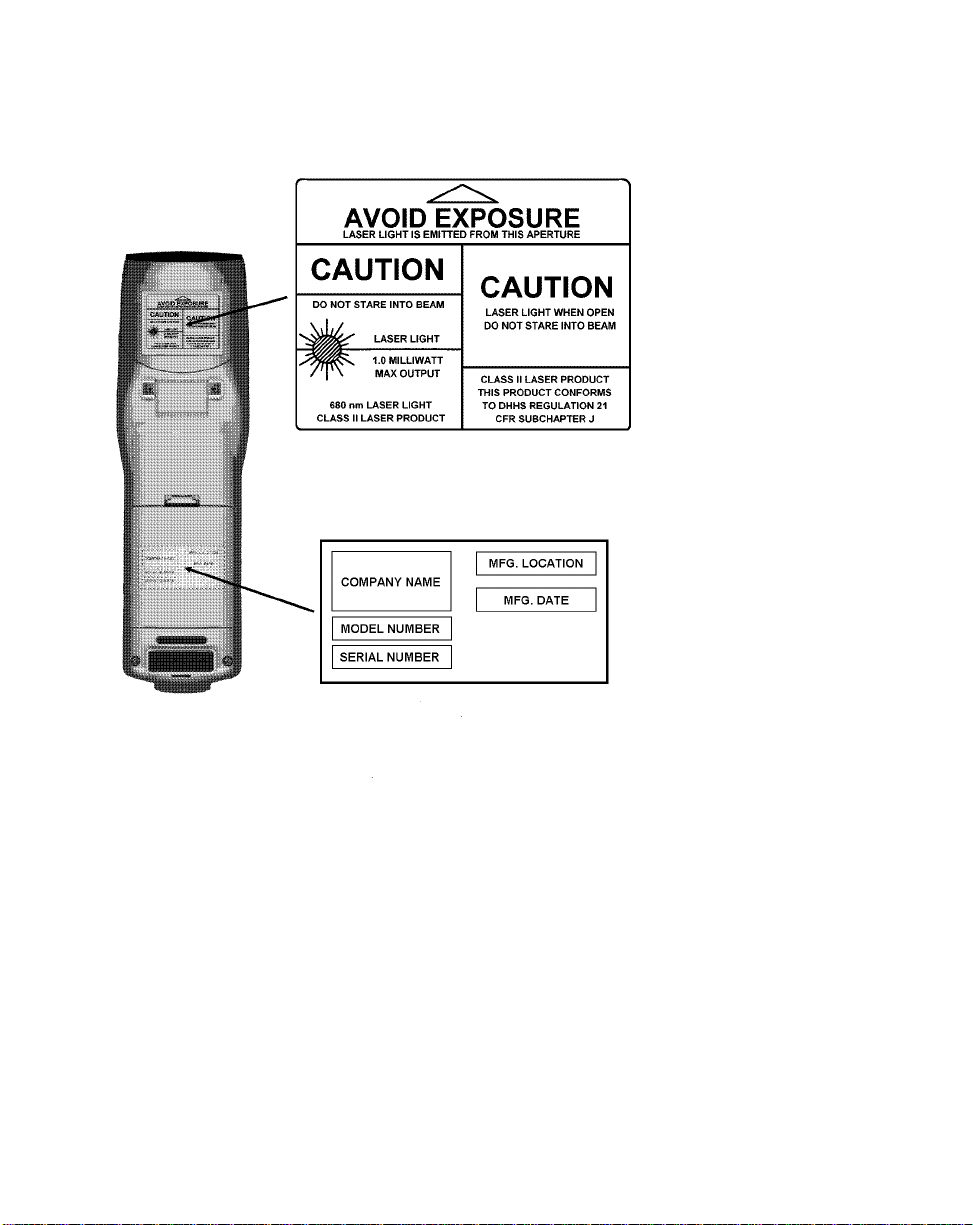
Using the internal short-range laser scanner
1.
2.
This label lists the location and date of manufacture,
the model number, and the serial number of the PTC.
It is permanently affixed inside the PTC’s battery
compartment.
1. Laser light exits the PTC
through this opening. Do
not stare into the beam!
3.
2. CAUTION! This Class II
laser product emits up to a
1-milliwatt beam of laser
light. Do not stare into the
beam!
4.
3. CAUTION! Laser light is
emitted when the PTC’s
protective housing is open.
Do not stare into the beam!
4. This PTC is a Class II laser
product. It conforms to the
Department of Health and
Human Services (DHHS)
Regulation 21 CFR Subchapter J.
These labels are permanently
affixed to the back of the PTC
below the scanner lens.
10
Page 13

Scope of the manual
This manual provides general information on the
PTC-960RL’s parts, features, and accessories. It also
explains how to operate and maintain the PTC.
This manual does not include the specific operating
instructions for your organization’s unique data
collection program. Operating instru ctions and
training should be available from your organization.
Document conventions
The following conventions are used throughout this
manual.
Warnings
Warnings indicate potential bodily injury or death.
They are set off in the left-hand columns of this
manual by the following symbol: $.
3
Cautions
Cautions indicate potential damage to equipment.
They are set off in the left-hand columns of this
manual by the following symbol: !.
Notes
Notes provide supplementary information. They are
set off in the left-hand columns of this manual and
are not preceded by a symbol.
11
Page 14

Overview of the PTC-960RL
The Telxon PTC-960RL is a compact, batterypowered, hand-held computer used to collect, store,
and transmit data. It has a built-in laser scanner and
may contain a spread spectrum radio.
The PTC-960RL automates your data collection
procedures and is custom programmed to efficiently
handle your organization’s unique data collection jobs.
The PTC runs an application program specially
designed to collect data for your organization. This
program leads you through the application with a
series of display messages, prompts, and beeps.
Messages tell you when you make an error and
provide information on the application or the PTC’s
status. Prompts and beeps tell you when to enter
data, what type of data to enter, and when you
complete certain operations.
4
Entering data
Entering data into the PTC-960RL is easy. You can
key in data through the keyboard or scan bar codes
with the internal laser scanner. Additionally, data can
be received through an optional internal DATASPAN
spread spectrum radio.
Through the keyboard
Entering data through the keyboard is similar to
operating a calculator. As you press the data keys, the
corresponding number or letter appears on the screen.
Pressing the ENTER key stores data in the PTC’s
memory.
12
Page 15

bar code
A
and spaces used on nearly every
item in business today.
is a series of vertical bars
With the internal laser scanner
A second method of entering data is with the PTC’s
internal laser scanner. When you scan a bar code the
PTC is programmed to read, the PTC and scanner
interpret the data and store it in the PTC’s memory.
Via a radio
Refer to pages 17 and 25 for information on radio
communication.
Storing data
Data entered into the PTC can be stored in files in the
PTC’s memor y.
Each file holds a separate group of application-related
data. For example, a PTC used to collect many types
of data (sales orders, inventory changes, and employee
hours) would store all data relating to sales orders in
one file, all data relating to inventory changes in
another, and all data relating to employee hours in
still another.
Communicating data
After collecting the data, the PTC must either
transmit it to a host computer for processing or send
it to a printer, or both, to make it useful to you and
your organization. The PTC-960RL can transmit data
through its optional internal radio, via an optional
communication cradle, or by being connected by cable
to a host computer, printer, or other accessory.
Once the host computer receives the data from the
PTC, it uses that data to update its master files and
records. In some cases, the host computer may even
transmit data back to the PTC, asking you, as the
PTC’s operator, to perform a new task.
13
Page 16

Getting started
Unpacking the PTC-960RL
5
Any additional accessories are
shipped separately.
If anything is missing or
damaged, notify your Telxon
sales representative.
Each shipping box contains
• a PTC-960RL with a handstrap,
• a nickel-cadmium battery pack or a 9-volt
alkaline battery,
• a battery charger (if ordered),
• a Guide to Maintaining NiCd Batteries,
• a PTC-960RL Read-Me-First Sheet, and
• a PTC-960RL User’s Guide.
1. Remove the PTC from the box.
2. Remove all packing material from the PTC. Save
the packaging in case the PTC is ever stored or
shipped to Telxon for service.
Check the contents of the package to make sure
3.
you have received everything ordered.
4. Check the PTC and accessories for shipping
damage. Pay particular attention to the PTC case,
display lens, and scanner lens.
Installing the battery
If your PTC was not shipped with the nickel-cadmium
battery pack or 9-volt alkaline battery installed,
follow the instructions in Chapter 11 to insert the
battery.
14
Page 17

Charging the nickel-cadmium battery pack
!
If you are using a 9-volt alkaline
battery in your PTC-960RL, replace
the old battery with a new battery
whenever you receive a low-battery
warning. You cannot charge alkaline
batteries.
The pack can also be charged via a
communication cradle or a fast battery charger. Contact your Telxon
representative for information.
To charge the battery pack outside
of the U.S. or Canada, you need a
charger designed for a 220-volt AC
outlet.
Charge the PTC-960RL’s nickel-cadmium battery
pack when you first receive the unit and whenever
the pack becomes weak. The Low Battery icon
appears on the ninth line of the display when the
battery is running out of power.
Use the following procedure to charge the PTC’s
nickel-cadmium battery pack via a battery charger.
Equipment required:
• A battery charger
• An electrical outlet within 6 feet (1.8 meters)
providing 110 volts AC in the U.S. or Canada
Make sure the PTC is off.
1.
Disconnect any accessories from the PTC.
2.
Connect the battery charger’s cable to the PTC’s
3.
micro DB-15 connector.
Plug the battery charger into the electrical outlet.
4.
The PTC’s Charging LED glows.
Charge the battery pack for 12 hours.
5.
When char ging is finished, disconnect the charger
6.
from the PTC and the outlet.
Turning on the PTC-960RL
Press the ON/OFF key to turn on the PTC-960RL.
1.
15
Page 18

Checking the PTC-960RL
Make sure the PTC is turned on.
1.
Look at the PTC’s display. What appears on the
2.
display depends on the program your organization
uses.
If the PTC is operating correctly, you should not
see or hear any of the following:
• A low-battery warning
• A blank display screen
• Any warning beeps
Repeat the steps in this chapter if your
PTC-960RL is not operating properly. If the
problem persists, refer to the “Troubleshooting”
section on page 34.
16
Page 19

Parts
Figures 1 and 2 on the following pages show and
describe the external parts of the PTC-960RL. The
parts listed below are internal and, therefore, are not
shown in either of the figur es.
6
Flash EPROM
A flash EPROM is an electronic component installed
inside the PTC. It contains the PTC’s data collection
program and determines the PTC’s key functions,
display prompts and messages, and how and when the
PTC collects or transmits data. If your PTC has an
internal radio, a second flash EPROM holds the
program that controls the radio.
For details on erasing and reprogramming flash EPROMs, refer to the
Guide to the Flash Utilities (TCAL or
MS-DOS Version)
Your application program controls
the radio. Refer to your application’s
manual for details.
.
These flash EPROMs can be erased and
reprogrammed while they are insid e the PTC. First,
the PTC must be connected to a host computer, via a
cable or by being placed in a communication cradle.
Then, using software in the PTC’s operating system,
you can erase the flash EPROM and reprogram it
with a new program from the host computer.
Radio (optional)
The PTC-960RL can be equipped with a DATASPAN
spread spectrum radio, which allows the PTC to
interactively communicate in real-time with a host
computer on a radio-based local area network. Spread
spectrum provides secure, interference-free
communication and does not require a license for
operation.
17
Page 20
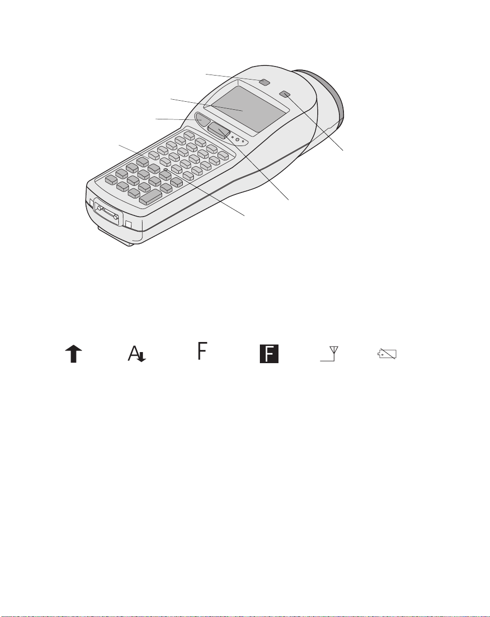
Figure 1. The PTC-960RL (front, bottom, and side view)
4. Good Scan LED
3. Display
2. Backlight button
1. Keyboard
5. Scanning LED
6. Scan button
7. Charging LED
1. The PTC-960RL’s keyboard can be used to enter data into the PTC and to perform special functions, such as turning the unit on or off.
2. The Backlight button turns the screen’s backlight on or off. It can also be used to control screen contrast. See page 22 for instructions.
3. The liquid crystal display (LCD) screen shows the information you type or scan into the PTC as well as messages from the PTC or host
computer. The screen can show 8 lines with 21 characters each. An additional line at the bottom of the display is reserved for status
indicator icons. These icons are as follows:
Shift Mode Enabled Caps Lock Enabled Func1 Is Activated Func2 Is Activated RF Out of Range Low Battery
4. T his green LED glows when the laser scanner has successfully read a bar code. You may also hear a beep after a successful scan.
5. T his red LED glows when the PTC’s Scan button has been pressed and the scanner starts to scan a bar code.
6. Pressing this button activates the PTC’s internal laser scanner, allowing you to scan bar codes.
7. T his LED glows when the PTC’s nickel-cadmium battery pack is being recharged.
18
Page 21
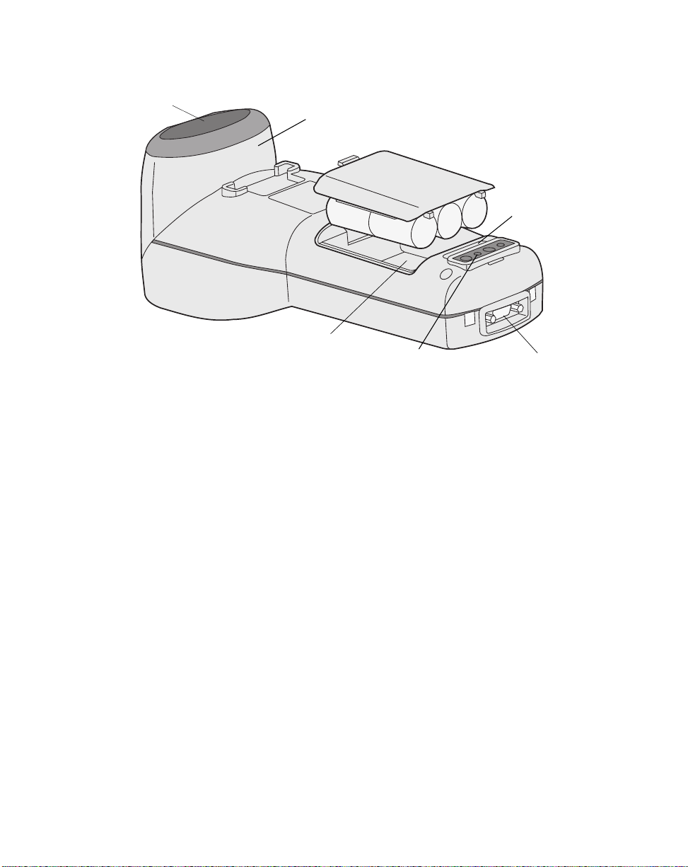
Figure 2. The PTC-960RL (back, bottom, and side view)
1. Scanner lens
2. Laser scanner
3. Handstrap bracket
6. Battery compartment
5. Optical coupler
1. The laser light emitted from the PTC’s internal laser scanner exits the unit through this lens.
$
Do not stare into the laser beam or point the scanner at anyone’s eyes; permanent eye damage could result.
2. T he PTC’s internal laser scanner is used to scan bar codes. T he scanner can be rotated 330 degrees to allow for straight-ahead, out-the-back,
or side-angle scanning.
3. An elastic strap attaches to this bracket. Use the strap to secure the PTC to the palm of your hand, making it easier to hold onto. To remove
the strap from the bracket, turn the triangle on the strap 45
4. This 15-pin connector connects the PTC via cable to a host computer or to standard serial devices such as printers and modems. It can also be
used with a battery charger to recharge the PTC’s nickel-cadmium battery pack.
5. The optical coupler allows the PTC to communicate with a host computer through an optional optical communication cradle. Instead of
sending data in the form of electronic signals through the micro DB-15 connector, the PTC sends the data in the form of pulses of light to
a similar coupler on the cradle. Then the cradle converts the pulses of light into electronic signals and transmits them to the host computer.
The cradle can also send data to the PTC via the optical coupler. Refer to the
cradle.
6. The battery that powers the PTC rests in this compartment. The PTC can use either a nickel-cadmium battery pack or a 9-volt alkaline
battery.
o
clockwise and release it.
SC-960RL/SC-960L User’s Guide
4. Micro DB-15 connector
for instructions on using the
19
Page 22

Features
Autodiscrimination between bar codes
7
See Appendix B for a list of bar-code
types your PTC can be programmed
to read.
Your PTC-960RL’s application program can read and
automatically discriminate between up to ten
different bar-code types. See the information provided
by your supervisor for the bar-code types your PTC
has been programmed to recognize.
Automatic off
To conserve battery power, the PTC-960RL
automatically turns itself off after approximately 1
minute of inactivity. The exact length of time depends
on your application program.
Automatic return at on
When you turn off the PTC-960RL (or when the PTC
turns itself off), it remembers where it was in the
application. Then, when you turn the PTC back on, it
returns to that same point in the application. You do
not need to review what you have done or perform
any other start-up function to find your place.
Backlight
The screen’s backlight lights up the screen and makes
information on the display readable in dark or dim
conditions. Pressing the Backlight button turns the
backlight on or off.
20
Page 23

Backup battery
!
Do not store a PTC-960RL for over
two months without charging or
replacing the battery. Both the main
battery and the backup battery will
be drained, and any data or programs loaded into the PTC’s memory
will be lost.
The PTC-960RL’s built-in backup battery provides
enough power to protect data stored in the PTC’s
memory when the nickel-cadmium battery pack or
alkaline battery is being replaced or if it runs out of
power. The backup battery system provides
approximately 20 minutes of protection when the
main battery is removed.
Beeper
The PTC’s beeper is used by the PTC and your
application program to warn you of problems or to
prompt you to take an action. For example, if your
application program has temporarily turned off a key,
the PTC will beep if you press that key.
Depending on your organization’s application
software, you may be able to control the beeper’s
volume. See the manual or information provided by
your organization.
Clock
The PTC-960RL has a built-in clock that keeps track
of the date (month, day, year, and day of the week) and
the time (hours, minutes, seconds, and tenths of
seconds). The clock op erates continu ou sly. How the
clock is used depends on your application program.
For example, the PTC can use the clock to show the
date and time on its display or to direct a printer to
place a time stamp on a report.
Communication
The PTC-960RL is capable of communicating with a
host computer through its optional internal radio,
through an optional communication cradle, or by
being connected directly via a cable. See the manual
21
Page 24

or instructions provided by your organization for the
proper communication procedure for your application.
Display contrast
You can increase or decrease the display contrast in
steps by performing one of the following procedures.
In DOS, press the FUNC key and then the Backlight
button. In TCAL, start at the system prompt and
press the Down Arrow key and then the Backlight
button.
Memory
The PTC-960RL’s internal memory is used to store
your organization’s application program and th e da ta
you type or scan into the PTC.
Refer to Appendix A for memory
specifications.
The amount of memory in your PTC dete rmines how
much data you can type in before you have to send it
to a host computer or print it. Various amounts of
memory are available from Telxon, and the amount
actually installed in your PTC has been determined
by your organization’s needs.
22
Page 25

$
Do not stare into the PTC’s laser
beam or point the scanner at anyone’s eyes. Doing so could cause
permanent eye damage.
Scanning bar-code labels
The PTC-960RL can be programmed to automatically
recognize, read, and discriminate between up to ten
bar-code types.
The bar-code types your PTC-960RL can read depend
on your PTC’s application program. See the
information provided by your organization and
Appendix B for a list of bar-code types the PTC can be
programmed to read.
Follow this procedure to scan bar-code labels with the
PTC-960RL’s built-in laser scanner.
Point the PTC-960RL at the label to be scanned.
1.
Because the scanner can be rotated, the label can
be read from several angles. The scanner can be
rotated 180
to read a label (see Figure 3).
o
clockwise and 150o counterclockwise
8
See the information provided by
your organization for the recommended scanning distance.
The maximum distance from the scan ner lens to
the label depends on the size of the label being
scanned.
2.Press the PTC’s Scan button to start scanning.
The red Scanning LED glows.
If your PTC is equipped with the aiming dot or
marker beam option, the laser projects a red
aiming dot. Quickly center the aiming dot over the
bar code. Continue pressing the Scan button until
the bar code has been scanned.
3.Watch the line of light made by the scanner as it
scans the bar code. The line must pass over all of
the bars on the label for the bar code to be read.
23
Page 26
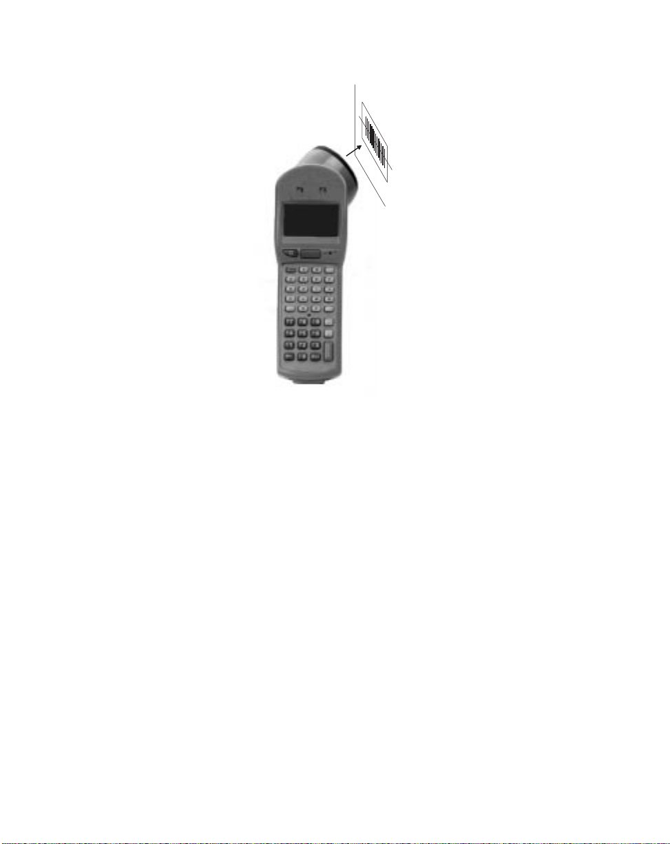
Figure 3. Scanning bar-code labels
Make sure the scan line extends
beyond both sides of the bar code
If the scan is not successful, move
closer to the bar-code label and try
to scan the label again.
If the scan is successful, the green Good Scan
LED glows, and the PTC beeps.
24
Page 27

Communicating data
The PTC-960RL is able to communicate with other
PTCs, c omputers, and external accessories such as
printers. It can both send and receive data and
instructions. Communication is controlled by your
organization’s application program. See the manual or
instructions provided by your organization for details
on conducting communication sessions.
The PTC-960RL is designed to use its internal radio
as its primary means of communicating with a host
computer, but it can also communicate by being
connected directly to the host computer via cable or by
being placed in a communication cradle that is
connected to the host computer. Accessories such as
printers are connected to the PTC with a cable.
9
Using the radio
All radio communication is controlled by your
organization’s application program. See the
instructions provided with the program for
information.
Refer to Appendix C for cable part
numbers.
Using the micro DB-15 connector
To connect the PTC-960RL to another PTC, host
computer, or accessory via the micro DB-15 connector,
you need the correct cable. Different cables may be
required depending on what you are connecting the
PTC to. See the manual or instructions your
organization supplies for your application program.
25
Page 28

!
Do not force any connectors together if they do not mate easily;
you could damage them.
Connecting a cable
1. Make sure you have the correct cable for the
device to which you are connecting. If you use the
wrong cable, the PTC may not be able to
communicate.
2. Turn off the PTC and the computer or accessory
to which you are connecting.
Connect the micro DB-15 connector on the
3.
appropriate cable to the PTC’s micro DB-15
connector.
4. Connect the other end of the cable to the
computer or accessory.
5. Turn on the PTC and then turn on the device to
which it is connected.
6. Follow the instructions for your application
program to communicate.
Disconnecting a cable
1. Turn off the PTC.
!
Pull on the cable connector’s head
when disconnecting. Pulling on the
cable can break the internal wires.
Refer to the
Guide
PTC-960RL with the cradle.
SC-960RL/SC-960L User’s
for instructions on using the
2. Turn off the attached computer or accessory.
Pull the cable’s connector directly away from the
3.
PTC’s micro DB- 15 connector.
4. If necessary, disconnect the other end of the cable
from the computer or accessory.
Using the optical communication cradle
The PTC-960RL’s optical coupler converts electronic
signals inside the PTC into pulses of light that can be
detected by the SC-960RL Single-bay Communication
Cradle.
26
Page 29

When the PTC-960RL is placed in the cradle, an
optical coupler on the cradle senses the pulses of light
from the PTC and converts them into electronic
signals for direct communication to the host computer
or, with an external modem, for transmission over
telephone lines. Likewise, the cradle can communicate
back to the PTC through the optical coupler.
27
Page 30

Maintaining the PTC-960RL
10
Operating conditions
The PTC-960RL should not be used in excessively
dirty or moist environments. It can be operated at
temperatures between 0 and 120 degrees F (-18 and
49 degrees C).
Handling the PTC-960RL
The following information will help to ensure you
receive safe, reliable, and trouble-free service from
your PTC-960RL.
• Do not stare into the laser beam.
• Do not point the scanner at anyone’s eyes. You
could cause permanent eye damage.
• Do not open the PTC’s case. Only a trained
technician may service the parts inside the PTC.
• If you store a PTC-960RL containing a nickel-
cadmium battery pack in below-freezing
temperatures for more than 1 hour, do not charge
the battery pack until it warms up to room
temperature. Charging cold battery packs can
damage them.
• Make sure the PTC is off before you connect or
remove any cables or accessories or replace the
battery.
• Make sure all accessories connected by cable are
connected correctly and the correct cables are used.
• Use only Telxon-approved batteries and
accessories. Do not attempt to connect any
electrical device that is not part of your PTC-960RL
system to the PTC.
28
Page 31

• Protect the PTC from excessive hea t, cold,
moisture, and harsh, dirty environments.
• Do not insert anything other than Telxon-approved
cables into the PTC’s micro DB-15 connector.
Storing the PTC-960RL
• Do not store the PTC-960RL in temperatures below
-20 degrees F (-29 degrees C) or above 140 degrees
F (60 degrees C).
• Do not store the PTC-960RL in a damp or humid
environment.
Transfer any data stored in the PTC to a host
1.
computer or another PTC or print the data. See
the manuals or instructions for your
organization’s application program for direction s.
2. Make sure you have a copy of any programs
stored in the PTC.
3. Disconnect all accessories from the PTC.
4. Recharge the PTC’s battery pack or replace the
alkaline battery.
!
Be careful not to scratch the
scanner lens when you clean it.
Scratches can reduce the scanner’s
effectiveness.
!
Do not soak the cloth and do
not spray or pour cleaning liquids
directly onto the PTC.
5. Pack the PTC in the original packing material or
in a padded box and put it in a safe place, away
from dust, dirt, humidity, and excessive cold.
Cleaning the PTC-960RL
Equipment required:
• A soft, lint-free cloth
• A nonabrasive liquid cleaner such as Windex
To clean the PTC-960RL, slightly moisten a soft,
clean, lint-free cloth with a mild, nonabrasive cleaner
and wipe the outside surfaces. Do not use a paper
towel.
®
29
Page 32

If the PTC-960RL becomes extremely dirty or if
liquids, dirt, or other foreign materials get inside the
case, co ntac t your Telxon service representative.
Servicing the PTC-960RL
Do not attempt to service the PTC. Only a trained
Telxon technician may service the PTC. Follow the
procedures se t up by your organization to have the
PTC serviced properly.
30
Page 33

Replacing the battery
11
!
Once you remove the PTC’s battery, the backup battery will protect
stored programs and data for approximately 20 minutes. After that,
all programs and data will be lost.
Use the procedures in this chapter to remove a weak
nickel-cadmium battery pack or alkaline battery from
the PTC-960RL and replace it with a new one. The
Low Battery icon appears on the PTC’s display when
the battery is running out of power.
Replacing the nickel-cadmium battery pack
Removing the battery pack
Turn off the PTC.
1.
Lay the PTC facedown on a flat surface.
2.
If a handstrap is attached to the PTC, turn the
3.
triangle on the bottom of the strap approximately
o
clockwise until you can remove it from the
45
handstrap bracket.
4. Insert your fingernail into the slot at the top of
the battery door and pull back, causing the door to
lift up. Remove the door from the unit.
Pull on the exposed ribbon (see Figure 4) to lift
5.
the battery pack out of the compartment.
Refer to page 9 for instructions on properly
6.
disposing of your nickel-cadmium battery pack.
31
Page 34
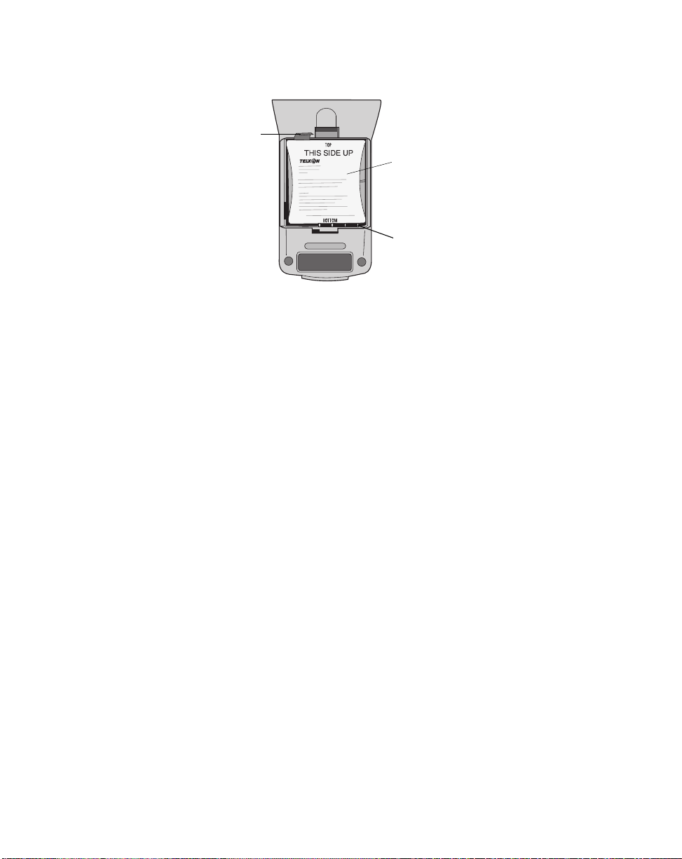
Figure 4. Replacing the nickel-cadmium battery pack
Battery pack ribbon
Installing a new battery pack
1.Hold the new battery pack over the battery
compartment, making sure the Telxon label is
facing you and the exposed battery contacts are
facing down. See Figure 4.
2.Insert the bottom end of the battery pack (with
the exposed contacts) into the compartment first
and then lower the opposite end.
Nickel-cadmium battery pack
Exposed battery contacts
A 9-volt alkaline battery may be
used in non-radio versions of the
PTC-960RL, but for optimal performance, Telxon recommends using a
rechargeable nickel-cadmium battery
pack.
Replace the battery door.
3.
Replacing the alkaline battery
If your PTC contains a 9-volt alkaline battery, it is
held in place by a foam block and connected to the
PTC via a 9-volt battery cable.
Removing the alkaline battery
1.Follow Steps 1 through 4 under “Removing the
battery pack” on page 31.
Remove the battery from the foam block; then
2.
unsnap the battery cable.
32
Page 35
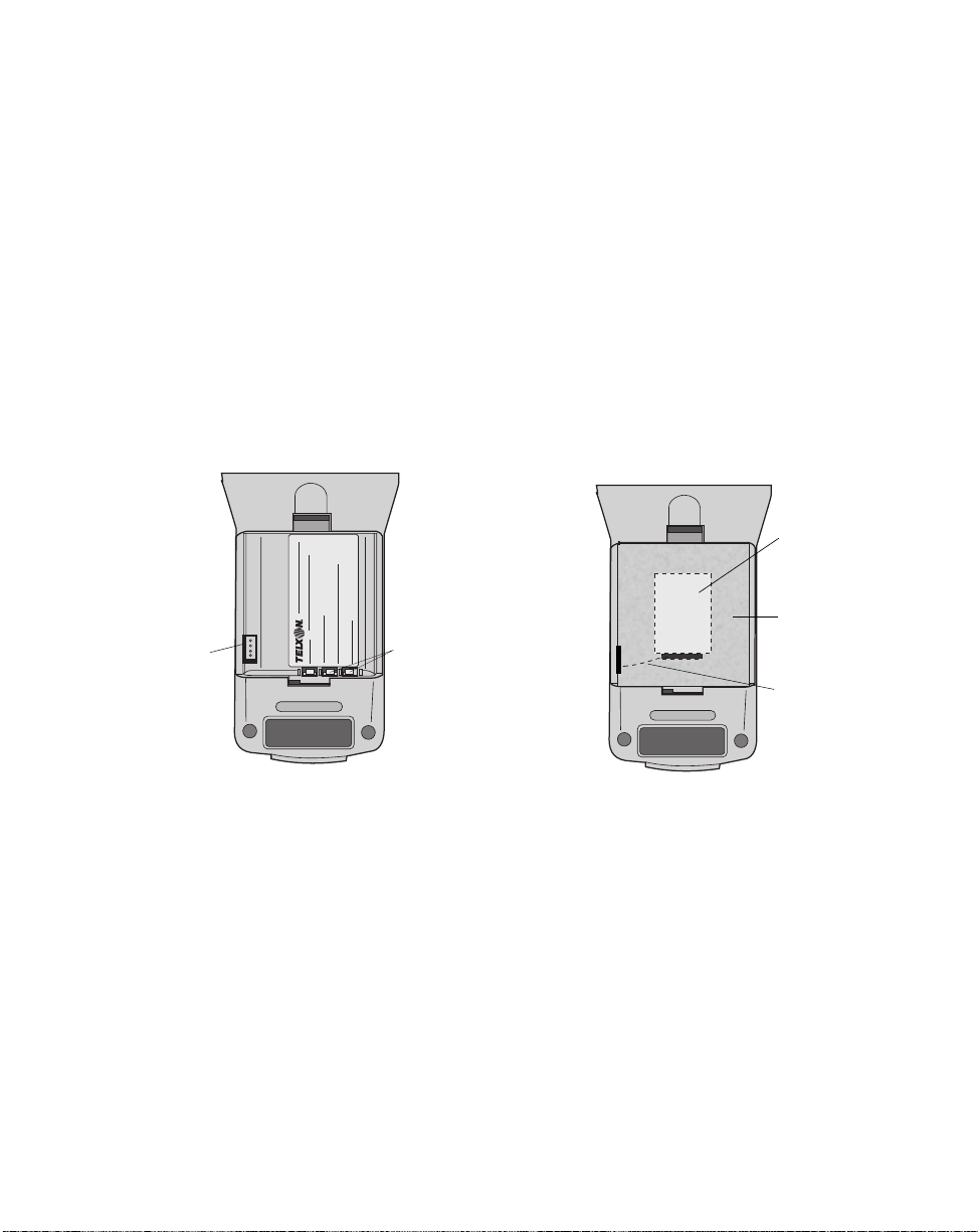
Installing a new alkaline battery
1. Snap the battery cable onto the replacement
battery.
!
Use the alkaline battery only when
the foam block is installed; otherwise, the battery case may short out
the nickel-cadmium battery contacts.
See Figure 5.
2. Insert the foam block into the battery
3.
4.
Figure 5. Installing a new alkaline battery
9-volt battery
cable connector
compartment, if it is not already installed.
Place the battery into the opening in the foam
block.
Replace the battery door.
9-volt alkaline
battery
Foam block
Nickel-cadmium
battery contacts
Battery cable
View of empty battery compartment
View of battery compartment with alkaline battery
installed, connected to 9-volt battery cable connector,
and held in place by foam block
33
Page 36

Troubleshooting
12
The PTC does not turn on
• Charge the nickel-cadmium battery pack or replace
the alkaline battery.
• If the PTC still does not operate, follow your
organization’s procedure to have the PTC serviced.
The laser scanner does not read a label
•
Make sure the bar-code label you are trying to scan
is one of the bar-code types your scanner has been
programmed to recognize.
• Move the PTC-960RL closer to or farther away
from the bar-code label. You may not be scanning at
the correct distance.
• Swivel the scanner to change the angle to the
bar-code label. The PTC may be too far above or
below the bar-code label or too far to the side to
scan properly.
• Wipe off the label and try again. The label may be
worn or dirty.
• Clean the scanner lens.
• Point the scanner at a blank surface and press the
Scan button. Look for the scanning line that
appears on the blank surface when the scanner is
operating. If no scanning line appears, follow your
organization’s procedure to have the PTC serviced.
Your radio fails to establish contact
• Change your location by a few feet and transmit
again.
34
Page 37

• Recharge the nickel-cadmium battery pack or
replace the alkaline battery.
• Make sure the receiving equipment is turned on
and is properly connected to the host computer.
• If your PTC still does not establish contact, follow
your organization’s procedure to have the PTC
serviced.
Other problems
If you experience any other problems with your
PTC-960RL, notify your Telxon service representative
or contact the Telxon Customer Support Center at
1-800-800-8010.
35
Page 38

Appendix
A
Specifications
Display
Type: FSTN LCD
Size: 8 lines by 21 characters
Screen icons: Shift Mode Enabled, Caps Lock
Enabled, Func1 Is Activated, Func2 Is
Activated, RF Out of Range, Low Battery
Resolution: 128 x 64 graphic pixels
Electrical
Battery power: 7.2-volt, 500-mAh rechargeable nickel-
cadmium battery pack (standard);
9-volt alkaline battery (optional)
Environmental
Operating 0 to 120 degrees F
temperature: (-18 to 49 degrees C)
Storage -20 to 140 degrees F
temperature: (-29 to 60 degrees C)
Humidity: 95% noncondensing
Electrostatic 15-kV shock causes no damage;
discharge: 8-kV shock causes no lock-up or
data loss
36
Page 39

Memory
RAM: 128 KB, expandable to 1 MB
ROM: 256-KB OS flash EPROM
256-KB application flash EPROM
Physical
Length: 9.5 in/24.1 cm
Width: 3.0 in/7.6 cm (at the display)
2.64 in/6.7 cm (at the keyboard)
Depth: 1.4 in/3.6 cm (at the keyboard)
Weight: 16.4 oz/.47 kg (with alkaline battery)
17.9 oz/.51 kg (with battery pack)
Processor
Microprocessor: V20H/80C88
Processing speed: 10 MHz (terminal processing)
Radio
Types: 900-MHz or 2.4-GHz DATASPAN
spread spectrum radio
37
Page 40

Bar-code types supported
Appendix
B
Other bar-code types may be available. Contact your Telxon representative for more information.
The PTC-960RL can be programmed to read and
automatically discriminate between up to ten of the
following bar-code types. See the information provided
by your organization for the specific bar-code types
your PTC-960RL is programmed to read.
•
UPC
• EAN
• Plessey
• Code 39
• Code 93
•
Code 11
• 2 of 5 - Straight, Interleaved, and Industrial
• Codabar
• Code 128
• Ames
38
Page 41

* These cables must be used with pigtail
communication cable 20955-002 or
21019-001.
** Use this cable with AC wall adapter
12176-000 or 10142-200.
Appendix
Accessory part numbers
Table 1 contains part numbers for ordering
PTC-960RL accessory hardware.
Table 1. Accessory part numbers
Item Part number
Accessories
9-volt alkaline battery
Alkaline battery cable
Alkaline battery foam block
Battery charger (AC adapter with DB-15)
Handstrap
Nickel-cadmium battery pack
SC-960RL Single-bay Communication
Cradle
Cables
Pigtail (12") micro DB-15-to-DB-25
adapter cable (with charging jack)**
Pigtail (12") micro DB-15-to-DB-25
adapter cable (w/o charging jack)
Micro DB-15-to-DB-9 adapter cable (6’)
Clone cable
PTC-to-1/2 duplex modem cable*
PTC-to-full duplex modem cable*
PTC-to-host (DTE) cable*
PTC-to-IBM PC/AT download cable*
3 ft/.91 m
6 ft/1.8 m
10 ft/3.05 m
PTC-to-IBM PC/XT download cable*
6 ft/1.8 m (female)
6 ft/1.8 m (male)
11695-000
20212-001
20815-000
20210-001
19656-001
20198-101
20520-001
20955-002
21019-001
21146-000
21018-001
10124-0X1
10124-0X2
10124-0X3
13656-313
13656-323
13656-333
10582-000
10582-110
C
39
Page 42

Item Part number
Manuals
Guide to Maintaining NiCd Batteries
Guide to the Flash Utilities (TCAL or
MS-DOS Version)
SC-960RL/SC-960L User’s Guide
16488-000
16541-000
21570-000
40
Page 43

Appendix
D
Communication connections
This chapter provides information on the connections
used to establish and maintain communication
between the PTC-960RL and other devices.
Table 2 lists the pinouts for the PTC-960RL’s micro
DB-15 connector. All I/O lines are directional and
support RS-232 voltage levels.
Figures 6 through 14 illustrate the configurations for
cables that can connect the PTC-960RL to other
devices.
Table 2. Micro DB-15 connector pinouts
Pin # Signal Description Direction
1OpenN.C.
2 TXD Transmit data Output
3 RXD Receive data Input
4 RTS Request to send Output
5 CTS Clear to send Input
6 DSR Data set ready Output
7GNDGround
8 CD Carrier detect Input
9 DTR Data terminal ready Output
10 RING Ring indicate Input
11 DS0 Device select zero Output
12 Open N.C.
13 Open N.C.
14 VCC Switched power +5 voltsOutput
15 VCHG Battery charge Input
41
Page 44
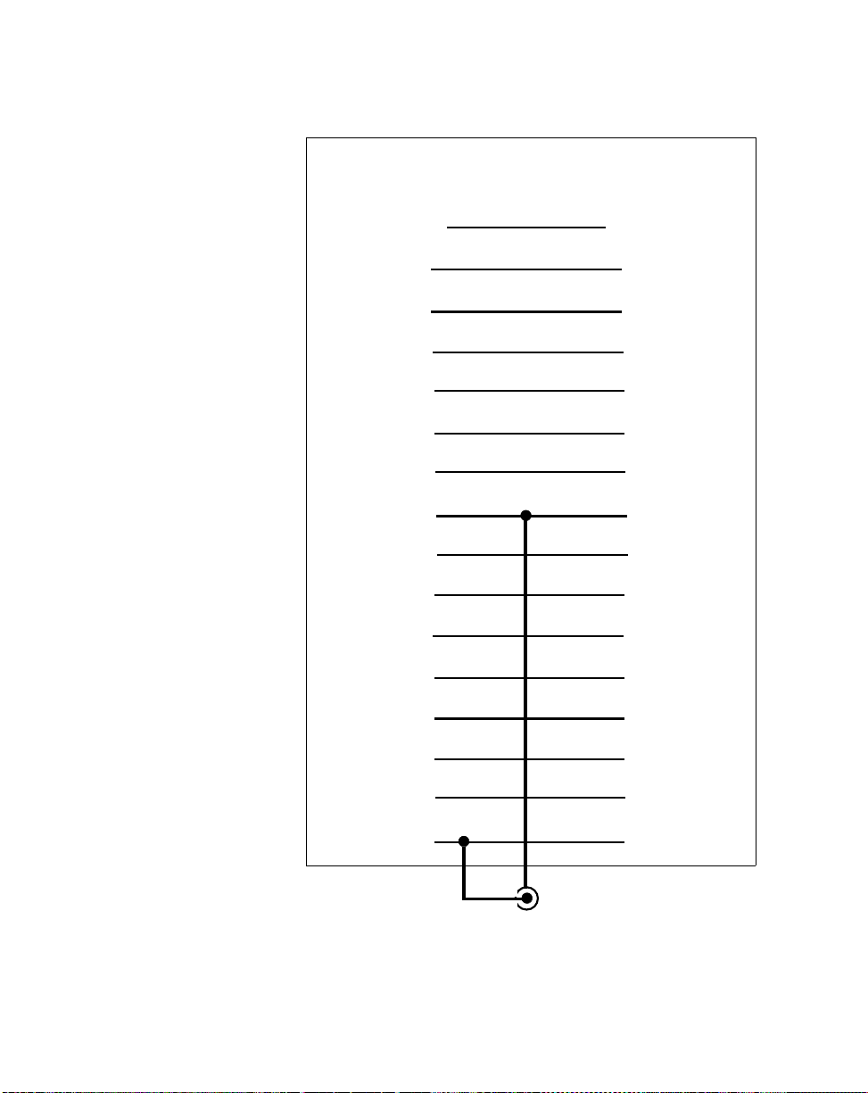
Figure 6. Pigtail micro DB-15-to-DB-25 adapter cable (w/ charging jack),
P/N 20955-002
PTC-960RL
Micro DB-15
Shield Shield
N.C. 1 1 N.C.
TXD 2 2 TXD
RXD 3 3 RXD
RTS 4 4 RTS
CTS 5 5 CTS
DSR 6 6 DSR
GND 7 7 GND
CD 8 8 CD
DTR 9 20 DTR
RI 10 22 RI
Other device
DB-25
DS0 11 12 DS0
N.C. 12 23 N.C.
N.C. 13 13 N.C.
VCC 14 9 VCC
VCHG 15 18 VCHG
12-volt charger input
42
Page 45

Figure 7. Pigtail micro DB-15-to-DB-25 adapter cable (w/o charging jack),
P/N 21019-001
PTC-960RL
Micro DB-15
VCHG 15 18 VCHG
DTR 9 20 DTR
TXD 2 2 TXD
CTS 5 5 CTS
RING 10 22 RING
DSR 6 6 DSR
RTS 4 4 RTS
RXD 3 3 RXD
GND 7 7 GND
N.C. 1 1 N.C.
CD 8 8 CD
DS0 11 12 DS0
N.C. 12 23 N.C.
N.C. 13 13 N.C.
Other device
DB-25
VCC 14 9 VCC
Shield Shield
43
Page 46

Figure 8. Micro DB-15-to-DB-9 adapter cable, P/N 21146-000
PTC-960RL
Micro DB-15
DTR 9 6 DSR
TXD 2 2 RXD
DSR 6 4 DTR
CTS 5 7 RTS
RTS 4 8 CTS
RXD 3 3 TXD
GND 7 5 GND
Shield Shield
IBM PC/AT
DB-9
44
Page 47

Figure 9. Clone cable, P/N 21018-001
PTC-960RL A PTC-960RL B
DTR 9 9 DTR
DSR 6 6 DSR
RTS 4 4 RTS
CTS 5 5 CTS
TXD 2 3 RXD
RXD 3 2 TXD
GND 7 7 GND
Shield Shield
45
Page 48

Figure 10. PTC-to-1/2 duplex modem cable, P/N 10124-0X1
PTC-960RL Modem/Type I
(1/2 Duplex)
TXD 2 2 TXD
RCV 3 3 RCV
DSR 6 6 DSR
DTR 20 20 DTR
RTS 4 4 RTS
CTS 5 5 CTS
RI 22 22 RI
CD 8 8 CD
SG 7 7 SG
-5 VDC 10
OUT 11
46
Page 49

Figure 11. PTC-to-full duplex modem cable, P/N 10124-0X2
PTC-960RL Modem/Type II
(Full Duplex)
TXD 2 2 TXD
RCV 3 3 RCV
DTR 20 20 DTR
DSR 6 6 DSR
RI 22 22 RI
CD 8 8 CD
SG 7 7 SG
RTS 4
CTS 5
-5 VDC 10
OUT 11
47
Page 50

Figure 12. PTC-to-host (DTE) cable, P/N 10124-0X3
PTC-960RL Host/Type III
(Full or 1/2 Duplex)
RXD 3 2 TXD
TXD 2 3 RXD
DTR 20 6 DSR
DSR 6 20 DTR
RTS 4
CTS 5 8 CD
4RTS
CD 8 5 CTS
SG 7 7 SG
OUT 11
-5 VDC 10
48
Page 51

Figure 13. PTC-to-IBM PC/AT download cable, P/N 13656-3X3
PTC-960RL IBM PC/AT
TXD 2 2 RXD
RXD 3 3 TXD
CTS 5 4 DTR
GND 7 5 GND
RTS 4 6 DSR
DSR 6 7 RTS
DTR 20 8 CTS
-5 VDC 10 9 RI
OUT 11 1 CD
49
Page 52

Figure 14. PTC-to-IBM PC/XT download cable, P/N 10582-XX0
PTC-960RL IBM PC/XT
Female (000)/Male (110)
TXD 2 3 RXD
RXD 3 2 TXD
RTS 4 6 DSR
CTS 5 20 DTR
DSR 6 4 RTS
GND 7 7 GND
DTR 20 5 CTS
-5 VDC 10
OUT 11
50
Page 53

Glossary
application A PTC program that is designed to perform a specific
task for the user. Examples include route accounting,
payroll, price lookup, shipping, and inventory control.
bar code A series of vertical bars and spaces used to encode
numeric or alphanumeric information. Bar codes are
designed to be read by electronic means such as
bar-code readers or laser scanners.
bps Bits per second.
byte A group of eight bits that acts as a basic unit for
information transfer and storage.
CD Carrier detect signal. CD indicates that the modem is
receiving a signal from the remote modem.
character A letter, number, or symbol.
CTS Clear-to-send signal. CTS indicates that the line
between a modem and a terminal device is clear for
transmission. CTS typically follows a raised
request-to-send (RTS) signal.
data
communication
The transport of encoded information from one point
to another.
DATASPAN Telxon’s spread spectrum radio.
DCE Data communications equipment. A device that
controls and converts incoming data or
communication. For example, a modem.
display The screen on the front of the PTC. It is used to show
data entered into the PTC and warning prompts.
51
Page 54

DSR Data set ready signal. The modem sends DSR to the
attached device to indicate that the modem is
connected, on, and ready.
DTE Data terminal equipment. A device comprising the
data source. For example, the host computer.
DTR Data terminal ready signal. The signal sent by the
terminal device to the modem to indicate that the
terminal is ready for transmission.
ESD Electrostatic discharge.
file
Any group or collection of related information stored
in memory. To add data to a file or to read data from a
file, the program must access the file by its file name.
flash EPROM A type of erasable programmable read-only memory
that can be erased and reprogrammed electronically
while installed in a PTC.
function key A key on the PTC’s keyboard that is defined by an
application to perform a specific task. When pressed,
a function key executes a certain function (for
example, ENTER, END, ON/OFF).
GND Ground.
hardware Equipment used in conjunction with programs or
data communication. Contrast with software.
host
computer
A personal computer or mainframe that receives and
processes data from PTCs.
Hz Hertz. A unit expressing frequency in vibrations per
second.
interface The connection between two devices, defined by
common physical characteristics, signal
characteristics, and signal meanings.
52
Page 55

I/O port Input/output port. The location on a PTC where
RS-232-compatible accessories are attached. Also, the
point through which the PTC sends and receives
transmission signals.
keyboard overlay The plastic label that lies on top of the PTC keyboard,
identifying the function key definitions.
laser scanner A type of bar-code reader that uses a beam of laser
light.
LCD Liquid crystal display.
LED
Light-emitting diode.
mAh Milliampere hour(s). A measurement of the ability to
provide electrical power.
modem Modulator-demodulator. A communication device that
converts serial digital data from a transmitting device
to a signal suitable for transmission over a telephone
line and then reconverts the signal to serial digital
data for the receiving device.
MS-DOS Microsoft Disk Operating System.
one-way
communication
Transport of information from one device to another
without interruption. In one-way communication, the
receiving device cannot respond directly to the
sending device.
prompt Messages shown by the PTC that guide the operator
through the steps of the application program.
Prompts are different for different programs.
PTC Portable Tele-Transaction Computer. A programmable
device used to collect, store, and transmit data.
RAM Random access memory. In a PTC, RAM chips store
the program files and data entered by the operator.
RF Radio frequency.
53
Page 56

RI Ring indicate signal. RI alerts a modem to a call
waiting on the attached telephone line.
ROM
Read-only memory. In a PTC, ROM chips contain the
operating system and the application program.
RS-232 An Electronic Industries Association (EIA) standard
that defines the connector, connector pins, and signals
used to transfer data serially from one device to
another.
RTS Request-to-send signal. RTS initiates the data
transmission sequence on a communication line
between a modem and a terminal device.
RXD Receive data signal. RXD indicates that a device is
currently receiving data.
signals Electronic impulses that transmit data from one
device to another.
software A stored program or set of programs that is loaded
into RAM for execution. Contrast with hardware.
spread
spectrum
A radio communication technology that distributes an
RF signal over a wide range of frequencies for
transmission; it then “despreads” the signal to the
original frequency range at the receiver.
TCAL Telxon Common Application Language. Telxon’s
proprietary programming language for PTCs.
two-way
communication
Exchange of information between two devices. After
each block of data, the receiving device sends a
positive or negative acknowledgment to the sending
device.
TXD Transmit data signal. TXD indicates that a device is
currently transmitting data.
VDC Volts direct current. A unit of measu re o f electric
potential or potential difference in a unidirectional
current.
54
Page 57

Index
A
Accessories, 25
connecting, 25-26
part numbers, 39-40
Alkaline battery, 19, 36
installing, 14, 33
removing, 32
Autodiscrimination between bar
codes, 20
Automatic off, 20
Automatic return at on, 20
B
Backlight, 20
Backlight button, 18, 22
Backup battery, 21
Bar codes, 13
autodiscrimination, 20
scanning, 23-24
types supported, 38
Battery charger, 15
Battery compartment, 19
Battery pack, 19, 36
charging, 15
charging time, 15
disposing of, 9
installing, 14, 32
removing, 31
Beeper, 21
Beeps, 12, 16
C
Cables, 39, 42-50
connecting, 26
disconnecting, 26
Caps Lock Enabled icon, 18
Charging the battery pack, 15
Charging LED, 15, 18
Checking the PTC-960RL, 16
Cleaning the PTC-960RL, 29-30
Clock, 21
Communicating data, 13, 25-27
via the micro DB-15 connector, 25-26
via the radio, 25
via the SC-960RL, 26-27
Communication, 21-22
Communication connections, 41-50
Communication cradle
See SC-960RL
Customer Support Center
contacting, 35
D
Data
communicating, 13, 25-27
entering, 12-13
storing, 13
DATASPAN radio
DOC statement, 8
FCC regulations, 8
Display, 18, 36
contrast, 22
55
Page 58

Document conventions
cautions, 5
notes, 5
warnings, 5
E
Electrical specifications, 36
Entering data, 12-13
with the internal laser scanner, 13
through the keyboard, 12
via a radio, 13
Environmental specifications, 36
F
Features, 20-22
Flash EPROM, 17
reprogramming, 17
Func1 Is Activated icon, 18
Func2 Is Activated icon, 18
G
Good Scan LED, 18, 24
H
Handling the PTC-960RL, 28-29
Handstrap
bracket, 19
removing from PTC, 31
Host computer
communication, 13
I
Icons, 18, 36
Caps Lock Enabled, 18
Func1 Is Activated, 18
Func2 Is Activated, 18
Low Battery, 15, 18
RF Out of Range, 18
Shift Mode Enabled, 18
Installing an alkaline battery, 14, 33
Installing a battery pack, 14, 32
K
Keyboard, 18
entering data, 12
Keys
ON/OFF, 15
L
Laser scanner, 19
entering data, 13
fails to read a label, 34
safety information, 10
LEDs
Charging, 15, 18
Good Scan, 18, 24
Scanning, 18, 23
Low Battery icon, 15, 18
M
Maintaining the PTC-960RL, 28-30
Memory, 22, 37
Messages, 12, 18
Micro DB-15 connector, 19
pinouts, 41
using, 25-26
56
Page 59

N
R
Nickel-cadmium battery pack
See Battery pack
O
ON/OFF key, 15
Operating conditions, 28
Operating temperature, 28, 36
Optical communication cradle
See SC-960RL
Optical coupler, 19
Overview of the PTC-960RL, 12-13
P
Packing material
saving, 14
Part numbers, 39-40
Parts, 17-19
Physical specifications, 37
Problems, 35
Processor specifications, 37
Prompts, 12
PTC-960RL
checking, 16
cleaning, 29-30
does not turn on, 34
features, 20-22
handling, 28-29
maintaining, 28-30
overview, 12-13
parts, 17-19
servicing, 30
storing, 29
troubleshooting, 34-35
turning on, 15
unpacking, 14
Radio, 17, 37
entering data, 13
fails to establish contact, 34-35
safety information, 9
specifications, 37
using, 25
Regulations
for DATASPAN radio, 8
general, 7
Removing an alkaline battery, 32
Removing the battery pack, 31
RF Out of Range icon, 18
S
Safety information, 9-10
SC-960RL
using, 26-27
Scan button, 18, 23
Scanner lens, 19
Scanning bar-code labels, 23-24
Scanning LED, 18, 23
Scope of the manual, 11
Servicing the PTC-960RL, 30
Shift Mode Enabled icon, 18
Shipping damage, 14
Specifications
display, 36
electrical, 36
environmental, 36
memory, 37
physical, 37
processor, 37
radio, 37
Spread spectrum, 17
Storage temperature, 29, 36
Storing data, 13
Storing the PTC-960RL, 29
57
Page 60

T
Troubleshooting, 34-35
Turning on the PTC-960RL, 15
U
Unpacking the PTC-960RL, 14
58
Page 61

!21568-701-02!
Telxon Corporation/3330 West Market Street, Akron, Ohio 44334/330-867-3700/800-800-8001
Part No. 21568-701-02 Printed in U.S.A.
 Loading...