

Page 1
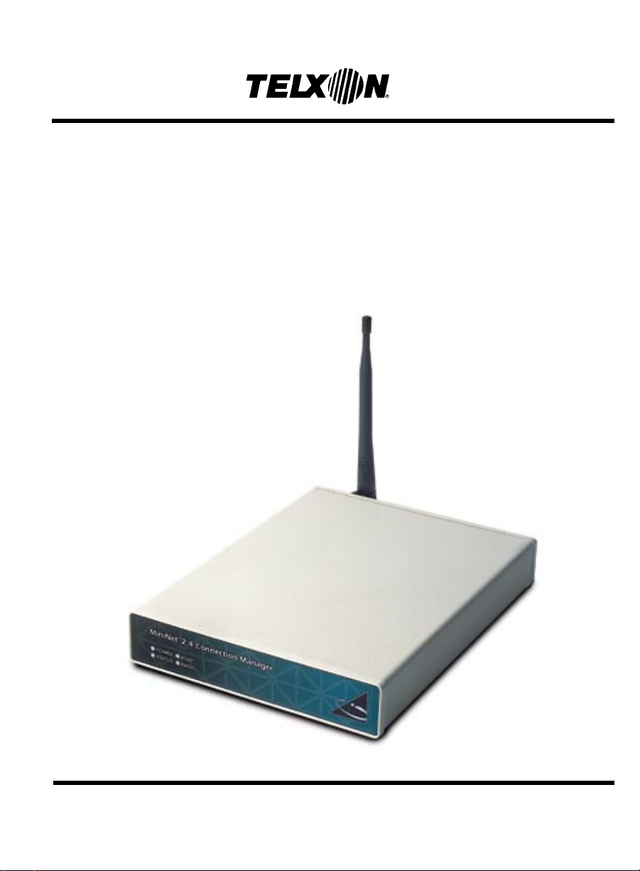
Connection Manager
User’s Guide
Page 2

Connection Manager
User’s Guide
Part Number: 23547-701-01
Release Date: 6/23/98
Page 3

Telxon is a registered trademark of Telxon
Corporation.
The information contained in this manual is subject
to chang e without notice.
Telxon Corporation shall not be liable for technical or
editorial omissions or mistakes in this manual nor
shall it be liable for incidental or consequential
damages resulting from your use of the information
contained in this manual.
This manual is copyrighted. All rights are reserved.
No part of this manual may be photocopied or
reproduced in any form without the prior written
consent of Telxon.
© Copyright 1998 Telxon Corporation
All Rights Reserved.
Page 4

Contents
Regulations . . . . . . . . . . . . . . . . . . . . . . . . . . . . . . 7
FCC statement . . . . . . . . . . . . . . . . . . . . . . . 7
DOC statement . . . . . . . . . . . . . . . . . . . . . . . 7
CE statement . . . . . . . . . . . . . . . . . . . . . . . . 8
MiniNet 2.4 radio regulations . . . . . . . . . . . . . . . 8
FCC statement . . . . . . . . . . . . . . . . . . . . . 8
FCC regulations . . . . . . . . . . . . . . . . . . . . . 8
DOC statement . . . . . . . . . . . . . . . . . . . . . 8
Safety information . . . . . . . . . . . . . . . . . . . . . . . . . . . 9
Scope of the manual . . . . . . . . . . . . . . . . . . . . . . . . . . 10
Document conventions . . . . . . . . . . . . . . . . . . . 10
Cautions . . . . . . . . . . . . . . . . . . . . . . . . . 10
Notes . . . . . . . . . . . . . . . . . . . . . . . . . . . 10
Overview of the Connection Manager . . . . . . . . . . . . . . . . . . . 11
Processor . . . . . . . . . . . . . . . . . . . . . . . . . . . 11
Operating system . . . . . . . . . . . . . . . . . . . . . . 11
Memory . . . . . . . . . . . . . . . . . . . . . . . . . . . 12
ROM . . . . . . . . . . . . . . . . . . . . . . . . . . . 12
RAM . . . . . . . . . . . . . . . . . . . . . . . . . . . 12
Radio . . . . . . . . . . . . . . . . . . . . . . . . . . . . . 12
Entering data . . . . . . . . . . . . . . . . . . . . . . . . 13
Storing data . . . . . . . . . . . . . . . . . . . . . . . . . 13
Getting started . . . . . . . . . . . . . . . . . . . . . . . . . . . . 14
Unpacking the Connection Manager . . . . . . . . . . . . 14
4
Page 5

Parts
. . . . . . . . . . . . . . . . . . . . . . . . . . . . . . . . . 15
Features
Installing the Connection Manager
. . . . . . . . . . . . . . . . . . . . . . . . . . . . . . . 18
. . . . . . . . . . . . . . . . . . . . 19
Connecting the antenna . . . . . . . . . . . . . . . . . . . 19
Positioning the Connection Manager . . . . . . . . . . . . 19
Connecting the Connection Manager to a host computer . 19
Via an RS-232 serial connection . . . . . . . . . . . . 19
Via an Ethernet network . . . . . . . . . . . . . . . . 20
Supplying power to the Connection Manager . . . . . . . 20
Maintaining the Connection Manager . . . . . . . . . . . . . . . . . . . 21
Operating conditions . . . . . . . . . . . . . . . . . . . . 21
Handling the Connection Manager . . . . . . . . . . . . . 21
Moving the Connection Manager . . . . . . . . . . . . . . 22
Cleaning the Connection Manager . . . . . . . . . . . . . 22
Storing the Connection Manager . . . . . . . . . . . . . . 23
Servicing the Connection Manager . . . . . . . . . . . . . 23
Troubleshooting . . . . . . . . . . . . . . . . . . . . . . . . . . . . 24
The Connection Manager does not turn on . . . . . . . . . 24
The Connection Manager fails to communicate with the
host computer . . . . . . . . . . . . . . . . . . . . . . . 24
A PTC fails to communicate through the Communication
Manager . . . . . . . . . . . . . . . . . . . . . . . . . . 25
The Status LED glows solid green . . . . . . . . . . . . . 25
Other problems . . . . . . . . . . . . . . . . . . . . . . . 25
Appendix A . . . . . . . . . . . . . . . . . . . . . . . . . . . . . . 26
Specifications . . . . . . . . . . . . . . . . . . . . . . . . 26
Communication and I/O . . . . . . . . . . . . . . . . . 26
Electrical . . . . . . . . . . . . . . . . . . . . . . . . . 26
Environmental . . . . . . . . . . . . . . . . . . . . . . 26
Mass storage . . . . . . . . . . . . . . . . . . . . . . . 27
Memory . . . . . . . . . . . . . . . . . . . . . . . . . 27
Physical . . . . . . . . . . . . . . . . . . . . . . . . . 27
5
Page 6

Processor . . . . . . . . . . . . . . . . . . . . . . . . 27
Software . . . . . . . . . . . . . . . . . . . . . . . . . 27
Appendix B
. . . . . . . . . . . . . . . . . . . . . . . . . . . . . . 28
Accessory part numbers . . . . . . . . . . . . . . . . . . . 28
Appendix C . . . . . . . . . . . . . . . . . . . . . . . . . . . . . . 29
LED codes . . . . . . . . . . . . . . . . . . . . . . . . . . 29
Appendix D . . . . . . . . . . . . . . . . . . . . . . . . . . . . . . 30
Pinouts . . . . . . . . . . . . . . . . . . . . . . . . . . . . 30
Glossary . . . . . . . . . . . . . . . . . . . . . . . . . . . . . . . 32
Index . . . . . . . . . . . . . . . . . . . . . . . . . . . . . . . . 36
6
Page 7

FCC statement
Regulations
1
!
Changes or modifications not
expressly approved by Telxon for
compliance could void the user’s
authority to operate the equipment.
This equipment has been tested and found to comply
with the limits for a Class A digital device, pursuant to
Part 15 of the Federal Communications Commission
(FCC) rules. These limits are designed to provide
reasonable protection against harmful interference
when the equi pment is operated in a commercial
environment. This equipment generates, uses, and
can radiate radio frequency energy and, if not
installed and used in accordance with this user’s
guide, may cause harmful interference to radio
communications. Operation of this equipment in a
residential area is likely to cause harmful interference, in which case users will be required to correct
the interference at their own expense.
DOC statement
This digital apparatus does not exceed the Class A
limits for radio noise emissions from digital apparatus
as outlined in the Radio Interference Regulations of
the Canadian Department of Commun ications (DOC).
This Class A digital apparatus meets all requirements
of the Canadian Interference-causing Equipment
Regulations.
Cet appareil numerique de la Classe A respecte toutes
les exigences du Reglement sur le material broilleur
du Canada.
7
Page 8

CE statement
This device has the European community’s CE mark
of approval.
MiniNet 2.4 radio regulations
FCC statement
The radio module within the Telxon Connection
Manager fully complies with FCC Part 15.247 limits
for intentional radiation as well as FCC Part 15.109
for unintentional emissions.
FCC regulations
The Connection Manager uses radio s (transceivers)
and radio communication in its operation. The
Connection Manager is a low-power transceiver
operating under FCC Part 15.247. No license is
required for operation.
DOC statement
The Connection Manager’s radio module is also
approved for use in Canada. No license is required for
operation.
This device complies with RSS-210 of Industry and
Science Canada. Operation is subject to the following
two conditions: (1) this device may not cause interference, and (2) this devi ce must accept any interferen ce,
including interference that may cause undesired
operation of the device.
8
Page 9

Safety information
The Telxon Connection Manager is compliant to the
ANSI C95.1 (1992) Standard for Safety Levels with
Respect to Human Exposure to Radio Frequency
Electromagnetic Fields per FCC Docket 93-62.
2
9
Page 10

Scope of the manual
This manual provides general information on the
Connection Manager’s parts and features. It also
explains how to install and maintain the unit.
Document conventions
Cautions
Cautions indicate potential damage to equipment.
They are set off in the left-hand columns of this
manual by the following symbol: !.
Notes
Notes provide supplementary information. They are
set off in the left-hand columns of this manual and
are not preceded by a symbol.
3
10
Page 11

Overview of the Connection Manager
The Telxon Connection Manager is designed primarily
for use in small stores with less than 12,000 square
feet. It acts as a communication link between the
store’s host computer and one or more Portable TeleTransaction Computers (PTCs). The Connection
Manager can send data to and receive data from the
host and the PTCs.
The Connection Manager is wired to the host computer via an RS-232 serial cable or can be connected
to an Ethernet network to which the host is connected.
The Connection Manager establishes wireless
communication links with PTCs used throughout the
store. The PTCs, which can consist of any combination
of up to eight PTC-921 DOS and/or PTC-960LE units,
and the Connection Manager communicate with each
other via their internal MiniNet 2.4 radio modules.
Light-emitting diodes (LEDs) on the Connection
Manager’s front panel indi cate the status of power
input, error conditions, and communication
connections.
4
Processor
The Connection Manager’s 66-MHz AMD Elan SC400
processor is fully IBM PC compatible. It provides
exceptional processing speed and is designed for low
power consumption.
Operating system
The Connection Manager uses the MS-DOS 6.22
operating system (ROM version) .
11
Page 12

Memory
The Connection Mana ger ha s two ty pe s of memory:
read-only memory (ROM) and random access memory
(RAM).
ROM
The Connection Manager comes with 256 kilobytes
(KB) of flash BIOS programmable read-only memory.
It is used to store the operating system, BIOS, and
flashing kernel.
RAM
The Connection Manager has 4 MB of random access
memory. RAM is used to store data the Connection
Manager needs while it is running. One MB of RAM
is reserved for running the operating system and your
application.
Data stored in RAM can be easily read, written, and
changed. It is also volatile. All data in RAM will be
lost if power to the Connection Manager is terminated.
Radio
The Connection Manager contains a MiniNet 2.4
low-power frequency-hopping radio module. This
radio allows the Connection Manager to interactively
communicate in real-time with PTCs on a radio-based
local area network. It provides secure, interferencefree communication and does not require a license for
operation.
12
Page 13

Entering data
Data can be entered into the Connection Manager via
its MiniNet 2.4 low-power frequency-hopping radio
module or through its RS-232 COM1 and COM2
serial ports or Ethernet port.
Storing data
Data entered into the Connection Manager can be
stored in the PTC’s RAM, on the internal 4-MB
IDE-compatible solid-state hard drive, or on 3.5-inch,
1.44-MB, high-density floppy diskettes (if your
Connectio n Manager was ordered with the o ptional
floppy drive).
13
Page 14

Getting started
Unpacking the Connection Manager
5
Any additional accessories are
shipped separately.
If anything is missing or
damaged, notify your Telxon
sales representative.
Each shipping box contains
a Connection Manager,
•
a 15-VDC, 2.7-A AC adap ter,
•
a 2.4-GHz antenna,
•
a Connection Manager Read-Me-First Sheet,
•
and
a Connection Manager User’s Guide.
•
1. Remove the Connection Manager from the box.
2. Remove all packing material from the Connection
Manager. Save the packaging in case the unit is
ever stored or shipp ed to Telxon for service.
Check the contents of the package to make sure
3.
you have received everything ordered.
4. Check the Connection Manager for shipping
damage.
14
Page 15

Parts
Figures 1 and 2 on the following pages show and
describe the external parts of the Connection
Manager.
6
15
Page 16
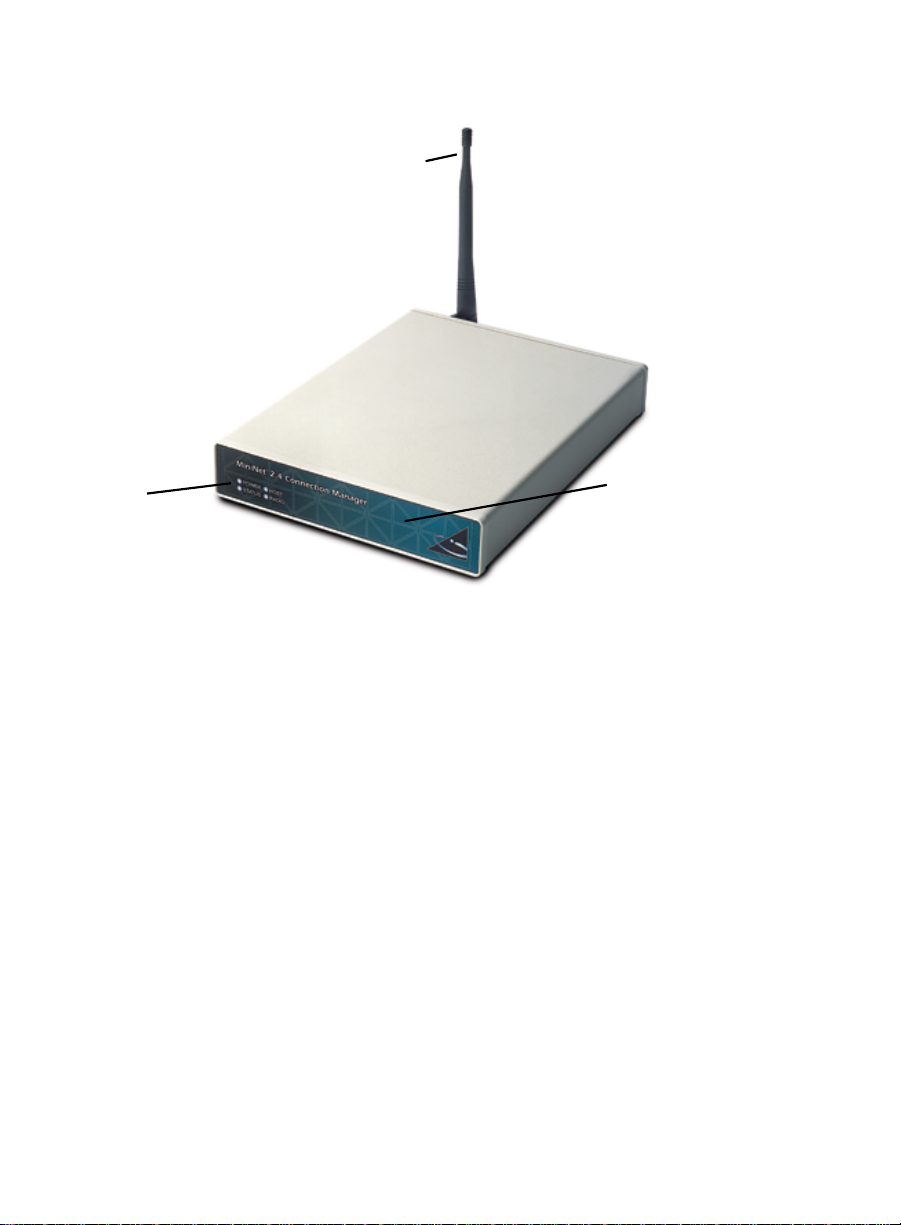
Figure 1. The Connection Manager (front view)
1. Antenna
2. LEDs
1. A 2.4-GHz antenna attaches to the antenna connector on the back of the Connection Manager. The antenna sends and receives radio
transmissions, allowing the Connection Manager to communicate with PTC-921 DOS and PTC-960LE units.
! Do not supply power to the Connection Manager or attempt to transmit data unless the antenna is attached; otherwise, the radio may
be damaged.
2. These four light-emitting diodes (LEDs) indicate the status of the Connection Manager and its connections. See Appendix C for a detailed
interpretation of the unit’s LEDs.
3. This optional drive accepts 3.5-inch, 1.44-MB, high-density floppy diskettes. The drive is designed to be used for simple, low-cost software
upgrades or to store data.
3. Floppy drive - optional
(not pictured)
16
Page 17
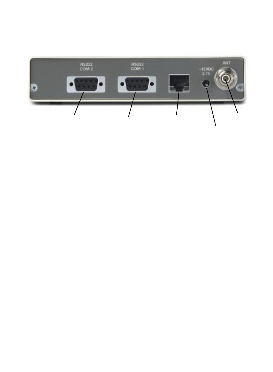
Figure 2. The Connection Manager (rear view)
1. RS-232 COM2 port
2. RS-232 COM1 port
3. Ethernet COM1 port
5. Antenna connector
4. Power jack
1. This 9-pin male connector provides an RS-232 serial interface to a host computer. A standard null-modem cable with a DB-9 connector is
required to make this connection. See Appendix B for a list of available cables and Appendix D for this port’s pinouts.
2. This 9-pin male connector provides an RS-232 serial interface to a local PC, laptop, or similar device. A standard null-modem cable with a
DB-9 connector is required to make this connection. See Appendix B for a list of available cables and Appendix D for this port’s pinouts.
3. This RJ-45 connector allows the Connection Manager to communicate with a host computer via an Ethernet network. An Ethernet
connection is established by connecting one end of a 10BaseT (twisted-pair) cable to the Connection Manager’s Ethernet port and the other
end of the cable to a twisted-pair hub on an Ethernet network. Appendix D lists this port’s pinouts.
4. A 15-VDC, 2.7-A AC adapter plugs into this connector and an electrical outlet to supply power to the Connection Manager.
5. A 2.4-GHz antenna attaches to this connector to enable radio communications between the Connection Manager and up to eight PTCs.
! Do not supply power to the Connection Manager or attempt to transmit data unless the antenna is attached; otherwise, the radio may
be damaged.
17
Page 18

Features
The Telxon Connection Manager performs the
following functions:
Incorporates a PC 486-compatible processor
•
operating at 66 MHz for high-speed performance
Links PTC-921 DOS and PTC-960LE units to a
•
host computer
Communicates with PTC-921 DOS and PTC-960LE
•
units via an internal MiniNet 2.4 low-power
frequency-hopping radio module
Provides a standard RS-232 serial interface to the
•
host computer or communicates with the host over
an Ethernet ne twork
Displays the status of power input, error conditions,
•
and communication connections via four LEDs
Provides an optional 3.5-inch floppy drive for
•
simple, low-cost software upgrades or for storing
data
7
18
Page 19

Installing the Connection Manager
Follow the instructions in this chapter (in the order
provided) to install the Connection Manager and
prepare it for operation.
Connecting the antenna
8
!
Do not supply power to the
Connection Manager or attempt to
transmit data unless the antenna is
attached; otherwise, the radio may
be damaged.
Screw the supplied 2.4-GHz antenna into the antenna
connector on the back of the Connection Manager.
Note: Other available antennas are listed in
Appendix B.
Positioning the Connection Manager
The Connection Manager is designed to rest on a flat
horizontal surface such as a table or shelf. Try to
position th e unit in an open, uncluttered area away
from much activity.
Connecting the Connection Manager to a host computer
Your Connection Manager can communicate with a
host computer via an RS-232 serial connection or
through an Ethernet network.
Via an RS-232 serial connection
Equipment required:
See Appendix B for a list of available
cables.
A standard null-modem cable with a DB-9
•
connector
19
Page 20

Make sure the Connection Manager is not
1.
connected to an electrical outlet.
If the connectors do not connect
easily, make sure they are lined up
correctly, no pins are bent, and
nothing is obstructing either
connector.
2. Connect the DB-9 connector on the null-modem
cable to the Connection Manager’s RS-232 COM2
port (if connecting to the s tore’s host computer) or
to the RS-232 COM1 port (if connecting to a local
PC, laptop, etc.).
Connect the other end of the cable to the host
3.
computer or other device.
Via an Ethernet network
Equipment required:
A 10BaseT (twisted-pair) cable
•
1. Make sure the Connection Manager is not
connected to an electrical outlet.
2. Plug the RJ-45 connector on the 10BaseT cable
into the Connection Manager’s Ethernet port.
3. Connect the other end of the cable to a twistedpair hub or concentrator on the Ethernet network
to which the host computer is already attached.
Supplying power to the Connection Manager
To use the Connection Manager
outside of the U.S. or Canada, you
need an AC adapter designed for
the country’s AC voltage supply
(e.g., 220 volts).
Equipment required:
A 15-VDC, 2.7-A AC adapter
•
An electrical outlet providing 110 volts AC in
•
the U.S. or Canada
Connect the AC adapter to the Connection Manager’s
power jack and an electrical outlet. The Power LED
glows solid green when the Connection Manager is
receiving power.
20
Page 21

Maintaining the Connection Manager
The Telxon Connection Mana g er is we ll con struct ed
and durable; however, it is a precision electronic
device and must be treated as such. Follow the
guidelines in this chapter to ensure reliable service.
Operating conditions
Although the Connection Manager is designed to
resist dust, dirt, and moisture, it should not be used
in excessively dirty or moist conditions. Operate the
Connection Manager only in temperatures between
32 degrees F (0 degrees C) and 122 degrees F (50
degrees C).
Handling the Connection Manager
Do not open the Connection Manager. No user-
•
serviceable parts are inside.
Do not supply power to the Connection Manager or
•
attempt to transmit data unless the antenna is
connected.
9
Make sure the Connection Manager is disconnected
•
from power before connecting or disconnecting any
cables.
Make sure the correct cables are used when
•
making connections.
Protect the Connection Manager from excessive
•
heat, cold, moisture, and harsh, dirty environments.
Do not leave the Connection Manager where
•
moisture can condense on it.
21
Page 22

Moving the Connection Manager
Follow these steps if you need to move the Connect ion
Manager or prepa r e it for shipment.
Disconnect the AC adapter from the electrical
1.
outlet and the Connection Manager.
Disconnect the antenna.
2.
Disconnect all other cables.
3.
If you are moving the Connection Manager a short
distance (to a new location in the same building for
example), you do not need to use a pack in g box.
Exercise care as you move the Connection Manager
to its new location; then follow the procedures in
Chapter 8 to reinstall the unit.
If you are shipping the Connection Manager, use the
original packing material and container, if available .
Otherwise, use a sturdy carton and adequate packing
material to protect the unit during shipment.
Cleaning the Connection Manager
Clean the outside of the Connection Manager
periodically with a soft cloth moistened with a mild,
non-abrasive cleaner, such as Winde x. Do not use
solvents or abrasive cleaners. Allow the unit to dry
thoroughly before reconnecting power.
If the Connecti on Manager becomes extremely dirty
or if liquids, dirt, or other foreign materials get inside
the case, contact your Telxon service representative.
22
Page 23

Storing the Connection Manager
• Do not store the Connection Manager in tempera-
tures below –22 degrees F (–30 degrees C) or above
140 degrees F (60 degrees C).
• Do not store the Connection Manager in a damp or
humid environment (over 95% noncondensing).
Pack the Connection Manager in the original packing
material or in a padded box and put it in a safe place
away from dust, dirt, humidity, and excessive heat or
cold.
Servicing the Connection Manager
Do not attempt to service the Connection Manager.
Only a trained T elxon technician may service the unit.
23
Page 24

Troubleshooting
10
The Connection Manager does not turn on
Make sure the AC adapter is properly connected
•
to the Connection Manager’s power jack and to a
functioning electrical outlet.
If the unit still does not turn on (indicated by
•
the Power LED), contact your Telxon service
representative.
The Connection Manager fails to communicate with the host computer
Make sure you are using the correct co nnecting
•
cable.
Make sure the cable is connected to the correct port
•
on both the Connection Manager and th e host.
Make sure the AC adapter is connected to the
•
Connection Manager’s power jack and is pl ugged
into a functioning electrical outlet.
Make sure the host computer has been turned on.
•
If the unit still fails to communicate, contact your
•
Telxon service representative.
24
Page 25

A PTC fails to communicate through the Communication Manager
• Make sure the PTC is on.
Make sure the Connection Manager is receiving
•
power. Check the AC adapter connections at the
Connection Manager and the electrical outlet.
• If the PTC still fails to communicate, contact your
Telxon service representative.
The Status LED glows solid green
If the Connecti on Manager’s Status LED glows solid
green, an error has occu rred . Contact your Telxon
service representative.
Other problems
If you experience any other problems or difficulties
with your Connection Manager that you cannot
solve, notify your Telxon service representative or
contact the Telxon Customer Support Center at
1-800-800-8010.
25
Page 26

Appendix
A
Specifications
Communication and I/O
MiniNet 2.4 radio
Type: 2.4 GHz, low power, frequency
hopping
Output: 8 mW
Transmit current: 5 VDC @ <200 mA
Data throughput: >100 Kbps
Typical indoor range: 150 to 200 ft/45.7 to 61 m
Serial ports
COM1: RS-232, male, DB9, up to 115 Kbps
COM2: RS-232, male, DB9, up to 115 Kbps
Ethernet port
COM1: Ethernet 10BaseT, RJ-45,
115 kbps or 10 Mbps
Antenna connector: Reverse TNC connector supporting
one external antenna
Electrical
AC adapter: Input: 90-240 VAC @ 50/60 Hz
Output: 15 VDC @ 2.7 A
Power jack: Input: 15 V D C @ 1.5 A
Environmental
Operating 32 to 122 degrees F
temperature: (0 to 50 degrees C)
Storage –22 to 140 degrees F
temperature: (–30 to 60 degrees C)
Relative humidity: 5 to 95% noncondensing
26
Page 27

Shock: 3-ft/.91-m drop to concrete
ESD protection: 15 kV
Mass storage
Hard drive: 4-MB SanDisk Compact Flash
IDE-compatible solid-state drive
Floppy drive: Optional 3.5-in ch , 1.44-MB drive
Memory
BIOS ROM (flash PROM): 256 KB
DRAM: 4 MB
Physical
Length: 9 in/22.9 cm
Width: 7.3 in/18.5 cm
Depth: 1.5 in/3.8 cm
Weight: 30 oz/.85 kg (without floppy drive)
51 oz/1.45 kg (with floppy drive)
Processor
Type: AMD Elan SC400
Speed: 66 MHz
Software
Operating sys t em : MS-DOS 6.22 (R O M ver s io n)
27
Page 28

Appendix
Accessory part numbers
The following table lists part numbers for ordering
Connection Manager accessories.
Table 1. Accessory part numbers
Item Part number
Accessories
AC adapter (15 VDC, 2.7 A)
Power supply
Power cord
2.4-GHz external antennas
8-in, omni-directional, swivel, whip
RTNC
3-db omni-directional, 3-ft coax
6-db directional corner reflector, 3-ft
coax
6-db hemispherical patch, 3-ft coax
13.5-db Yagi
20991-000
09038-000
18488-000
18506-000
18383-000
18384-000
19729-000
B
RS-232 serial cables
Asynchronous null-modem cable,
DB9F to DB25F, DTE to DTE, 10 ft
Asynchronous null-modem cable,
DB9F to DB25M, DTE to DTE, 6 ft
Asynchronous null-modem cable,
DB9F to DB9F, DTE to DTE, 6 ft
Manuals
PTC-921 DOS User’s Guide
PTC-960LE User’s Guide
P-80910-000
13656-323
16025-000
23451-000
23053-000
28
Page 29

Appendix
LED codes
This appendix interprets the Connection Manager’s
light-emitting diodes (LEDs).
Table 2. LED codes
LED Color Description
C
Power Solid
green
Status Solid
green
Blinking
green
Host Blinking
green
Radio Blinking
green
Input power is available
An error has occurred
Normal operation
Host data link is active
Radio data link is active
29
Page 30

Appendix
Pinouts
This section lists the pinouts of the Connection
Manager’s COM1 and COM2 ports.
D
1 2 3 4 5
o o o o o
o o o o
6 7 8 9
Table 3. RS-232 COM1 and COM2 serial port pinouts
Pin Signal Description
1 CD Carrier detect
2 RXD Receive data
3 TXD Transmit data
4 DTR Data terminal ready
5GND Ground
6 DSR Data set ready
7 RTS Request to send
8 CTS Clear to send
9 RI Ring indicate
30
Page 31

Table 4. Ethernet COM1 port pinouts
Pin 1
Pin Signal Description Twisted-pair number
1 TXD+ Transmit data output + TP2-1
2 TXD– Transmit data output – TP2-2
3 RXD+ Receive data input + TP3-1
4 NC No connection TP1-1
5 NC No connection TP1-2
6 RXD– Receive data input – TP3-2
7 NC No connection TP4-1
8 NC No connection TP4-2
Case Shield Ground Shield
31
Page 32

Glossary
application A PC, mainframe, or PTC program that is designed to
perform a specific task for a user. Examples include
route accounting, payroll, price lookup, shipping, and
inventory control.
asynchronous
transmission
A transmission with variable time intervals between
successive data characters. In asynchronous communication, each character is framed by start and stop bits.
BIOS Basic Input/Output System.
bit The fundamental binary unit, either a 1 (on) or a 0
(off). In ASCII code, seven bits repres ent one char acter
of data.
bps Bits per second. A rate of electronic data transmission.
CD Carrier detect signal. CD indicates that the modem is
receiving a signal from the remote modem.
CTS Clear-to-send signal. CTS indicates that the line
between a modem and a terminal device is clear for
transmission. CTS usually follows a raised requestto-send (RTS ) signal.
data
communication
The transport of encoded information from one device
to another.
DCE Data communications equipment. A device that
controls and converts incoming data or communication. For example, a modem.
DOC Department of Communications – Canada.
DSR Data set ready signal. The modem sends DSR to
the attached device to indicate that the modem is
connected, on, and ready.
32
Page 33

DTE Data terminal equipment. A device comprising the
data source. For example, the host computer.
DTR
ESD
FCC
frequency-hopping
(FH) radio
Data terminal ready signal. The signal sent by the
terminal device to the modem to indicate that the
terminal is ready for transmission.
Electrostatic discharge.
Federal Communications Commission – U.S.A.
A type of radio that continually jumps from one
frequency to another to avoid interference.
GND Ground.
hardware Equipment used in conjunction with programs or
data communication.
host computer A personal computer or mainframe that processes
and stores data supplied by other devices.
Hz Hertz. A unit of frequency equal to one cycle per
second.
interface The connection betwe en two devices, defined by
common physical characteristics, signal characteristics, and signal meanings.
I/O Input/output.
LAN Local area network. A radio network that supports
data communication within a local area, such as
within a warehouse or building.
LED Light-emitting di od e. Th e LED s se r ve as in d i ca to r
lights on the Connection Man ager.
mA Milliampere. A measurement of the ability to provide
electrical power.
33
Page 34

modem Modulator-demodulator. A communication d evice that
converts serial digital data from a transmitting
device to a signal suitable for transmission over a
telephone line and then reconverts the signal to serial
digital data for the receiving device.
MS-DOS
network
port
Microsoft Disk Operating System.
An interconnection of computer systems , terminals ,
and data communication facilities.
A connector on the Connection Manager through
which data and instructions are sent to and received
from other devices.
PTC Portable Tele-Transaction Computer. A programmable,
battery-powered, ha nd-h eld devi ce used for colle cting,
storing, and transmitting data.
RAM Random access memory. RAM chips store program
files and entered data.
RI Ring indicate signal. RI alerts a modem to a call
waiting on the attached telephone line.
ROM Read-only memory. In the Connection Manager, ROM
stores the operating system, BIOS, and flashing
kernel.
RS-232 An Electronic Industries Association (EIA) standard
that defines the connector, the connector pins, and the
signals used to serially transfer data from one device
to another.
RTS Request-to-send signal. RTS initiates the data
transmission sequence on a communication line
between a modem and a terminal device.
RXD Receive data signal. RXD is the data that is being
received.
signals Electronic impulses that transmit data from one
device to another.
34
Page 35

software A stored program or set of programs that is loaded
into RAM for execution.
two-way
communication
The exchange of information between two de vices.
After each block of data, the receiving device sends a
positive or negative acknowledgment to the sending
device.
TXD Transmit data signal. TXD is the data that is being
transmitted.
VAC Volts alternating current. A unit of measure of
electric potential or potential difference in a
bidirectional electrical current.
VDC Volts direct current. A unit of measure of electric
potential or potential difference in a unidirectional
electrical current.
35
Page 36

Index
A
AC adapter, 17, 20
specifications, 26
Accessories, 14
part numbers, 28
Antenna, 16
connecting, 19
part numbers, 28
Antenna connector, 17, 26
B
BIOS, 12
C
Cables, 17, 19-20
part numbers, 28
CE statement, 8
Cleaning the Connection Manager, 22
COM1 port
See Serial ports
COM2 port
See Serial ports
Communication, 11
Communication and I/O
specifications, 26
Communication problems, 24-25
Connecting to a host computer, 19-20
Connection Manager
cleaning, 22
handling, 21
installing, 19-20
maintaining, 21-23
moving, 22
operating conditions, 21
overview, 11-13
parts, 15-17
positioning, 19
servicing, 23
specifications, 26-27
storing, 23
supplying power to, 20
unpacking, 14
Customer Support Center
contacting, 25
D
DOC statement, 7, 8
Document conventions
cautions, 10
notes, 10
E
Electrical specifications, 26
Entering data, 13
Environmental specifications, 26-27
Ethernet connection, 20
Ethernet port, 13, 17, 26
pinouts, 31
F
FCC regulations, 8
FCC statement, 7, 8
36
Page 37

Features, 18
Floppy drive, 13, 16, 18, 27
H
Handling the Connection Manager, 21
Hard drive, 13, 27
Host computer, 17
communication, 11, 18
connecting to the Connection
Manager, 19-20
Host LED, 29
I
Installing the Connection Manager,
19-20
L
Operating temperature, 21, 26
Overview of the Connection Manager,
11-13
P
Packing material
saving, 14
Part numbers, 28
Parts of the Connection Manager 15-17
Physical specifications, 27
Pinouts, 30-31
Power jack, 17, 26
Power LED, 20, 24, 29
Processor, 11, 18
specifications, 27
PTCs
communication problems, 25
types supported, 11, 16, 18
LEDs, 11, 16, 18
Host, 29
Power, 20, 24, 29
Radio, 29
Status, 25, 29
M
Maintaining the Connection Manager,
21-23
Memory, 12, 27
MiniNet 2.4 radio, 12, 13, 18
regulations, 8
specifications, 26
Moving the Connection Manager, 22
O
Operating conditions, 21
Operating system, 27
R
Radio LED, 29
RAM, 12, 13, 27
Regulations
CE, 8
DOC, 7
FCC, 7
MiniNet 2.4 radio, 8
ROM, 12, 27
RS-232 serial connection, 19-20
S
Safety information, 9
Scope of manual, 10
Serial ports, 26
COM1, 13, 17, 20
COM2, 13, 17, 20
pinouts, 30
37
Page 38

Servicing the Connection Manager, 23
Shipping damage, 14
Specifications, 26-27
Status LED, 25, 29
Storage temperature, 23, 26
Storing the Connection Manager, 23
Storing data, 13
Supplying power to the Connection
Manager, 20
T
Troubleshooting, 24-25
U
Unpacking the Connection Manager, 14
38
Page 39

!23547-701-01!
Telxon Corporation/3330 West Market Street, Akron, Ohio 44334/330-664-1000/800-800-8001
Part No. 23547-701-01 Printed in U.S.A.
 Loading...