

cod. 988250
inverter
TROUBLESHOOTING
AND REPAIR MANUAL
TROUBLESHOOTING
AND REPAIR MANUAL
“trouble-free repair !”
TECHNOLOGY TIG
INVERTER REPAIR
LABORATORY
INVERTER REPAIR
LABORATORY
7
5426
8
13
2
TECHNOLOGY TIG
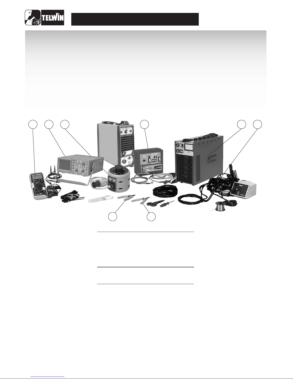
ESSENTIAL INSTRUMENTS
USEFUL INSTRUMENTS
MISCELLANEOUS
1 Oscilloscopio 20Mhz dual-trace cod. 802401
2 Static load generator cod. 802110
3 Variac 0 - 300v 1Kw cod. 802402
4 Power supply unit HV cod. 802403
5 Digital multimeter
6 Unwelding station
7 Flat-jaw pincers
8 Cutting nippers
(*)
(*)
(*)
(*)
Dismantling the inverter (see fig. 8)
A) Ensure that the power supply cable is disconnected from the mains..
B) Unscrew the 12 screws located at the four corners of the two blak plastic shells.
C) Slide out firstly the upper shell and then the lower shell.
D) Unscrew the two screws located below the wording "Technology TIG 165 "on the inverter side panel (13 , 14).
E) Slide out the casing by gently pulling it upwards.
F)
Once you have completed the repair, proceed in reverse order to re-fit the casing and the shells, ensuring that the fold on the
upper part of the shell is fitted inside the frame and the lower part of the side walls is fitted outside the frame.
(*) The instruments with codes can be supplied by TELWIN. Sale price on request.

3
TECHNOLOGY TIG
1) Clean and visually check the
inverter
2) Checking the power and signal
cables.
3) Electrical measurements while the
machine is off.
Open the inverter shell and clean thoroughly using
compressed air.
Dirt is dangerous mainly in the power areas of the inverter
which are subject to high voltage or for those components
galvanically separatingthe primary from the secondary.
Thus, check carefullythe following components:
Clean and check whether on the primary coil there are cuts or
cracks which could jeopardize the insulation of the secondary.
(Tig 165 DC/HF version.).
code 112478
(Tig 165 DC/HF version)
with high silicone insulation which connect the
H.F. transformer to the filter board and from the filter board to
the inverter shunt. (Tig 165 DC/HF 165 version.)
Check whether on the power transformer T1 or near
connector Jp1 there are signs of burns.
Visually check the post-gas and the gradual decreasing
of current potentiometers, the 2-4 phases electrode
and relays k1,k2.
These components must NOT have signs of dents, in
particular, the rotation of the potentiometers shaft
must be perfectand free from mechanical slacks.
(see Technology Repairs Manual)
(see Technology Repairs Manual)
( see Technology Repairs Manual )
(see Technology Repairs Manual)
check the cables fasten on connectors
J1, J2, J3. Specifically, check carefully the wires of connector
Jp1 in that there are subject to alternating network voltage.
check Cn01, Cn02, Fs01, Fs02
(See Technology Repairs Manual.)
1) H.F.Transformer:
2) H.F.Filter
3) H.F. Box
4) Electrovalve
5) Check cables
(See figure 2.)
A)
B)
7) Primary board:
8) Secondary board:
(See Figure 3-5)
1) Primary board:
2) Secondary board:
3) Tig control board:
4) Filter board:
(see Figure 2).
cod. 1124886) Control board Tig:
4) Electrical measurements while the
machine is in operation.
1)
(see figure 2).
2)
(See Figure 1.)
3)
4)
Warning!
the technology 114187 primary board cannot be mounted
on this machine.
5)
6)
- Jp1 Connector
- J2 Connector
- J1 Connector
7) Checking the operation of H.F. filter board, code 112478.
8) Checking the operation of tig control board, code 112488.
Disconnect the powersupply cablesof H.F.Box
Shortcircuit Jp2 on the primary board by means of a jumper
(placed between the SMD board and the electrolytic
condensers.
Remove all connectors from the tig control board. The inverter
is now set to work as a technology 165 with the switch located
on the front panel, in a central position ("hard welding").
Now follow the repair and test procedures of the inverter,
keeping in mind the following information:
1) the yellow led is not present on the board
2) the inverter carries the arc force and hod start functions.
Although the repair and test procedure are similar,
Remove the shortcircuit from Jp2 and put the connectors,
which were previously taken off from the tig control board, in
their places.
Switch the inverter on and check the following power supplies
on the tig control board:
Tester set in Vac
1) Place test prods on pins 1, 2 and you should have
220 Vac */- 10%
Tester set in Vac
Place test prods on pins 7, 8 and you should have 9
Vac +/- 10%.
1) Place negative test prod on pin 2 (mass) and
positive test prod on pin 1. The voltage should be +12
V +/- 3%.
2) Place negative test prod on pin 2 and positive test
prod on pin 3. The voltage should be -12 V +/- 3%.
- Ensure that the trimmer of pre-gas R 64 is rotated
counterclockwise.
Insert the tig torch and set the tig at two phases, press the torch
push-button. The electrovalve should be excited and, after a
short delay, the high frequency should be excited too. If this does
not happen, shortcircuit pins 1,2 on connector J2.
If both the electrovalve and the high frequency are excited, it
means that there a failure on the filter board, probably due to the
following components:
a) Bridge rectifier P01.
b) Relay Rl1
c) The alternating voltage 9 V on connector Cn 01 pin 7,
8 is missing.
d)The wire on thetorch is cut off.
A J4 jumper is mounted on this board (see Figure 3), which
allows you to select two operation modes:
precedentemente tolti dalla scheda controllo tig.
Guide to repair of the inverter Tig

TECHNOLOGY TIG
4
R53) is properly set, thewelding arc should strike.
b) Release the torch push-button, check the gradual
decreasing of current and thepost-gas potentiometers.
a) Set the switch located on the front panel at 4-phase
position ( ).
b) Bring the tugsteno electrode in contact with the element to
be welded, press and release the torch push-button then lift
the electrode for about 2 mm; the welding arc should strike.
In order to obtain a gradual decreasing of current, you must
press and release the torch push-button for the second
time.Finally, check whetherthere is a post-gas.
Switch the remote control on (code 802109) and ensure that it
works correctly.
Warning! The following remote control adjusts the current in
function of the current set on the front panel; thus, if we set a
value of 50 A on the inverter, we could adjust this value from 5
A to 50 A by actingon the remote control.
Switch the "tig pulse" box on (code 802320) and ensure that
it works correctly by checking the current parameters relative
to peak, pause and work phases.
If striking a welding arc by means of high frequency proves to be
difficult (weak high frequency), the failure could be due to the
following components:
-Torch
- High frequency box
- High frequency transformer
- High frequency filter
- Primary coil with inverted polarity
If after having replaced these components the failure persists, we
suggest to check carefully the high frequency silicone insulated
cable as well as the high frequencytransformer connection on the
positive inverter, which must NOT touch the carpentry or the wire
of the torch push-button. Furthermore, we suggest you
disassemble the positive dinse plug and check for signs of
discharges due to high frequency.
There are two types of tig control board and high frequency
transformers:
Tig control board
High frequency transformer
- The twotig controlboards are perfectly compatibleinsofar as the
tig 165 DC-HF is concerned (high frequency striking).The board
with code 112453 instead, cannot be mounted on tigs with lift
striking (tig 161 DC-LIFT).
- The high frequency transformer in Figure 8 is equipped with a
different mechanical fastening system thus, should you need to
make a replacement on atig mounting a transformer like the one
in Figure 5, you must drill three new holes on the carpentry
3) Checking the 4-phase cycle.
Checking the remote control.
1)
2)
High frequency striking
(See Figure 4-5)
(See Figure 6-7)
(see
Figure 6).
5) Changes and Updates
Jumper set towards connectors J1, J2 (H),
high frequency striking (tig 165 DC-HF).
Jumper set towards pre-gas and lift trimmers (L),
"lift" striking (tig 161 DC-LIFT).
Ensure that the aforementioned jumper is in H position.
Set the machine in electrode through the commutator.
Through static load or directly in welding, ensure the correct
operation of the inverter. (See "Final Testing" in Paragraph 5 of
the Technologic Repairs Manual.)
Set the inverter up for tig welding. (Connect torch and
argon gas bottle.)
Set the switch at two phases ( ) down slope and post-
gas potentiometers at the middle of the scale, the pregas trimmer at the minimum (the trimmer is inside the
board).
Press the torch push-button:
The high frequency and thegas electrovalve shouldexcite.
If after two seconds the welding arc does not strike, the
high frequency will automatically disexcite. On the other
hand, if the arc strikes, the current should reach the
value of about 80 A; when releasing the torch pushbutton the current decreases gradually for about 2-3
seconds. From this time on, the electrovalve remains
excited for about 3 seconds.
Repeat the same testing procedure, however turning the pre-
gas trimmer clockwise and setting it at the maximum. By
pressing the torch push-button, the electrovalve will excite
but the highfrequency will set offafter a 4-second delay.
Set this trimmer as to have a 2-second delay or
according to the customer's needs.
Set the commutator at 4 phases ( ).
Repeat the preceding testing procedures, keeping in mind
that, in order to strike the arc you must press thetorch pushbutton.When releasing it, the welding current will remain at
the preset value(80 A).If the operator pressesand releases
the torch push-button for a second time, the gradual
decreasing of current and thepost-gas phases will begin.
Bring the electrode in contact with the element to be welded; if
you do not press the torch push-button, the yellow led
(D26) located on the front panel should switch on.
Set the welding current of the post-gas and the gradual decreasing
of current potentiometers as you didfor the two-phasecycle.
A) Set the switch on front panel at two-phase( ) bring the
tugsteno electrode in contact with the element to be
welded, the led located on the front panel will switch on,
press the torch push-button. Through the plier-shaped
amperometer connected to the mass cable, check whether
there is a flow of current of about 20 A +/- 3 A. Should you
need to reset this value, act on trimmer R53.(In this phase,
the yellow ledis switched off.)
a) Bring the tugsten electrode in contact with the element to
be welded, press the torch push-button and lift the
electrode by about 2 mm. If the lift current (20 A trimmer
A)
B)
1)
2)
3)
4)
A) Checking the Tig 165 DC/HF machine cycle
1)
2)
3)
4)
5)
B) Checking the Tig 161 DC-LIFT machine cycle
1) Checking the lift current:
2) Checking lift striking and the 2-phase cycle.
 Loading...