

Telwin TECNICAPLASMA18-31 Troubleshooting And Repair Manual
TECNICA 140.1 - 142
cod. 988567
inverter
TECNICA PLASMA 18 -31
TROUBLESHOOTING
AND REPAIR MANUAL
TROUBLESHOOTING
AND
REPAIR MANUAL
“reparation no problem !”
CONTENTS PAGE
OPERATION AND WIRING DIAGRAMS................ 2
REPAIR GUIDE.......................................................10
SPARE PARTS LIST...............................................17
REPAIR SHEET......................................................19
Block diagram 2
Analysis of the block diagram 3
Illustrations 5
Wiring diagrams 6
Equipment required 10
General repair instructions 11
Troubleshooting and remedies 11
Testing the machine 14
Illustrations 16
TROUBLESHOOTING
AND REPAIR MANUAL
TROUBLESHOOTING
AND
REPAIR MANUAL
20/09/04
TECNICA PLASMA 18 - 31
-2-
24
25
UNDERVOLTAGE
SAFEGUARD
27
26
11
12
13
17
30
19
21
1
2
3
4
5
6
7
8
9
10
14
15
16
18
FAN
POWER SUPPLY
LED
FLY-BACKPOWER
SUPPLY
DRIVER
OUTPUT
CURRENT
TRANSFORMER
INDUCTANCE
PRIMARY
EMC FILTER
POWER
TRANSFORMER
23
PLASMA
CYCLE
CONTROL
20
TORCH POWER
LED
22
IGBT THERMOSTAT
34
33
29
28
32
31
PILOT ARC
RESISTANCE
OUTPUT
CURRENT
POTENTIOMETER
GALVANIC
SEPARATOR
AIR RALAY
GALVANIC
SEPARATOR
TORCHE BUTTON
AIR SOLENOID
VALVE
AP
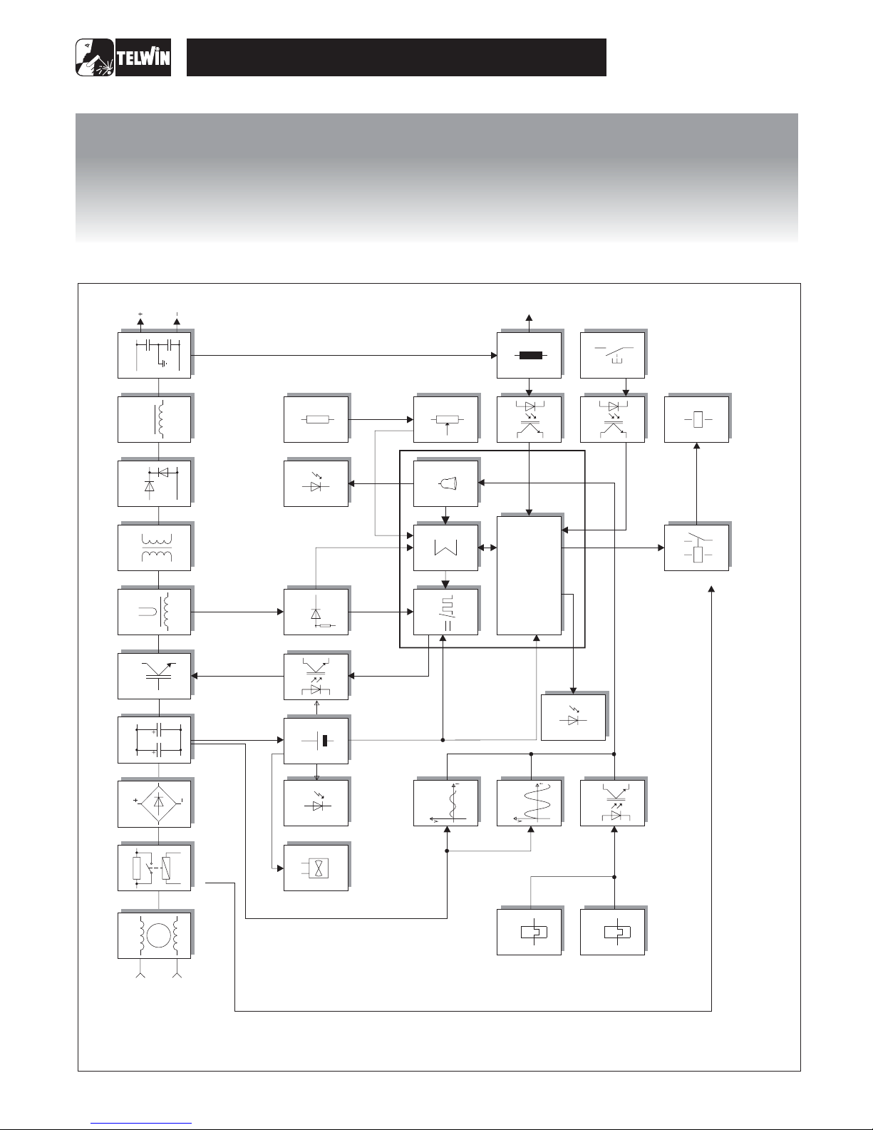
BLOCK DIAGRAM
OPERATION AND WIRING DIAGRAMSOPERATION AND WIRING DIAGRAMS
OPERATION AND WIRING DIAGRAMSOPERATION AND WIRING DIAGRAMS
PRE-CHARGE
RECTIFIER BRIDGE
FILTER
CHOPPER
SECONDARY
DIODES
SECONDARY
EMC FILTER
PRIMARY CURRENT
READER AND
LIMITER
DUTY CYCLE
MAKER
ALARM LED
MAXIMUM
CURRENT ADJUST.
OVERVOLATGE
SEFEGUARD
POWERED
TRANSFORMER
THERMOSTAT
ADDER
ALARM BLOCK
GALVANIC
SEPARATOR
INPUT

-3-
ANALYSIS OFTHE BLOCK DIAGRAM
Block 1
Block 2
Block 3
Block 4
Block 5
Block 6
Block 7
Block 8
NOTE:Unlessindicatedotherwise, it should be assumed that
thecomponentsareassembledontheprimaryboard.
Consistingof:C1, L1,C5,C6.
Preventsnoisefromthemachine from being transmittedalong
themain powerline andviceversa.
Consistingof:K1, R1.
Prevents the formation of high transitory currents that could
damage the main power switch, the rectifier bridge and the
electrolyticcapacitors.
When the power source is switched on the relay K1 is deenergised, capacitors C2, C3, C4 are then charged by R1.
Whenthe capacitorsarecharged therelayisenergised.
Consistingof:D1.
Convertsthemainsalternating voltageinto continuouspulsed
voltage.
Consistingof:C2, C3,C4.
Converts the pulsed voltage from the rectifier bridge into
continuousvoltage.
Consistingof:Q1, Q2.
Converts the continuous voltage from the filter into a high
frequency square wave capable of piloting the power
transformer.
Regulates the power according to the required welding
current/voltage.
Consistingof:T2.
TheC.T.isused tomeasurethe currentcirculatingin thepower
transformer primary and transmit the information to block 14
(primary currentreaderand limiter).
Consistingof:T3.
Adjusts the voltage and current to values required for the
welding procedure. Also forms galvanic separation of the
primary from the secondary (welding circuit from the power
supplyline).
Consistingof:D36, D37,D38.
D36 converts the current circulating in the transformer to a
singledirection, preventingsaturationofthe nucleus.
D37, D38 recirculate the inductance output current (block 9)
when the IGBT's are not conducting, bypassing the power
transformer(block7).
EMC Filter
Pre-charge
Rectifier bridge
Filter
Chopper
Current transformer
Powertransformer
Secondary diodes
Block 9
Block 10
Block 11
Block 12
Block 13
Block 14
Block 15
Block 16
Block 17
Inductance
Secondary EMC Filter
Flyback power supply
Driver
Primary current readerand limiter
Duty cycle maker
Adder
Alarm Block
Alarm LED
Consistingof:L2.
Levels the secondary board diodes’ output current making it
practicallycontinuous.
Consistingof: C50, C51.
Prevents noise from the power source from being transmitted
throughthe weldingcablesandviceversa.
Consistingof:T1,U2.
Uses switching methods to transform and stabilise the voltage
obtained from block 4 (filter) and supplies auxiliary voltage to
powerblock12 (driver)and thecontrolboard correctly.
Consistingof:ISO2, ISO3.
Takes the signal from block 11 (flyback power supply) and,
controlled by block 14 (duty cycle maker), makes the signal
suitableforpiloting block6 (chopper).
Consistingof: R37, R38andpartof thecontrolsection.
Readsthe signal from block6(current transformer)and scales
it down so it can be processed and compared in blocks 14 and
15.
Consistingof:U2 (controlboard).
Processes the information from block 15 (adder) and block 13
(primary current reader and limiter) and produces a square
wave with variable duty cycle limiting the primary current to a
maximumpre-set valueunder allcircumstances.
Consistingof:U1C,U1D(control board).
Gathers all the information from block 13 (primary current
reader and limiter), from block 16 (alarms) and from block 18
(current potentiometer), and produces a signal with a suitable
voltageforprocessing byblock14(duty cyclemaker).
Consistingof:U1A, U1B(controlboard).
When an alarm is detected the power source output current is
drastically reduced by making direct adjustments to block 14
(duty cycle maker) and directly changing the reference signal
obtainedfrom block18 (currentpotentiometer).
Consistingof:D26.
Itis switchedon byblock16(alarms)intheeventof:
1) Triggering of thermostatic capsule/thermostat on power
transformer.
2) Triggering of thermostatic capsule/thermostat on IGBT
dissipator.
3) Triggeringduetoundervoltage.
4) Triggeringduetoovervoltage.
TECNICA PLASMA 18 - 31

-4-
Block 27
Block 28
Block 29
Block 30
Block 31
Block 32
Block 33
Block 34
Fan
Torch button
Torch button galvanic separator
Torch powered LED
Air relay
Air solenoid valve
Pilot arc resistance
Pilot arc galvanic separator
Consistingof:V1.
Powered directly by block 11 (flyback transformer) and cools
thepowercomponents.
Consistingof:plasma torch.
Pressing the torch button strikes the pilot arc and enables the
air solenoid valve. The signal is re-dimensioned to enable
processingbyblock29.
Consistingof:ISO1A.
The signal from block 28 is separated galvanically and sent to
block 22 (plasma cycle control) which will process the
information.
Consistingof:D35 yellowLED.
This lights up under instruction from block 20 (plasma cycle
control) when the torch button is pressed and it indicates that
thecutting circuitisactivated.
Consistingof:K2.
Thisis energised underinstructionfromblock20(plasmacycle
control) and activates block 32 (air
Consistingof:solenoid valve.
Supplies the compressed air, to permit pilot arc strike, and is
necessaryfortorchoperationand cooling.
Consistingof:R43 andR44.
Allowsthe pilot arc tostrikefor amaximumof2 seconds.Within
this time the electric arc should have been transferred to the
pieceof iron to be cut: if not block 20 (plasma cycle control) will
resetthe completecuttingcycle.
Consistingof:ISOD andISOB.
The signal from block 33 is separated galvanically and sent to
block20 (plasma cycle control) forcorrect management of the
plasmacutting cycle.
solenoid valve) when
thetorchbuttonis pressed.
TECNICA PLASMA 18 - 31
Block 18
Block 19
Block 20
Block 21
Block 22
Block 23
Block 24
Block 25
Block 26
Current potentiometer
Maximum current adjustment
Plasma cycle control (control board)
Powertransformer thermostat
IGBT thermostat
Galvanic separator
Overvoltage safeguard
Undervoltage safeguard
Powersupply LED
Consistingof:R42.
This is used to set the reference voltage needed to adjust the
output current: when the potentiometer knob is turned the
cursor voltage varies, thus varying the current from the
minimumto themaximumvalue.
Consistingof:R32, R33,R42.
Used to adjust the maximum cutting current to be supplied by
thepowersource.
Logiccontrolboardthatmanagestypicaltimingforthe plasma
cuttingcycle withthecontact torch.
Consistingof:ST2.
When the temperature of the power transformer is too high,
this safeguard is triggered. It is reset automatically after the
alarm conditionhas ceased.
Consistingof:ST1.
When the temperature on the IGBT dissipator reaches a preset level the thermostat triggers to indicate an alarm to block
23 (galvanic separator). Reset is automatic when the alarm
conditionceases.
Consistingof:ISO1C.
The signal from blocks 21 and 22 (thermostats) is separated
galvanically and sent to block 16 (alarms) for identification of
possiblealarm condition.
Consistingof:R3, R4andpartof thecontrolsection.
If the main supply voltage exceeds the maximum value this
safeguard triggers (a tolerance of approx.±15% of the power
supply voltage is allowed: outside this range the safeguard
triggers).
Consistingof:R5, R6andpartof controlboard.
If the main supply voltage falls below the minimum allowed
value this safeguard triggers (a tolerance of approx.±15% of
the power supply voltage is allowed: outside this range the
safeguardtriggers).
Consistingof:D2.
Indicates when the power source is correctly powered and
readyforuse.
-5-
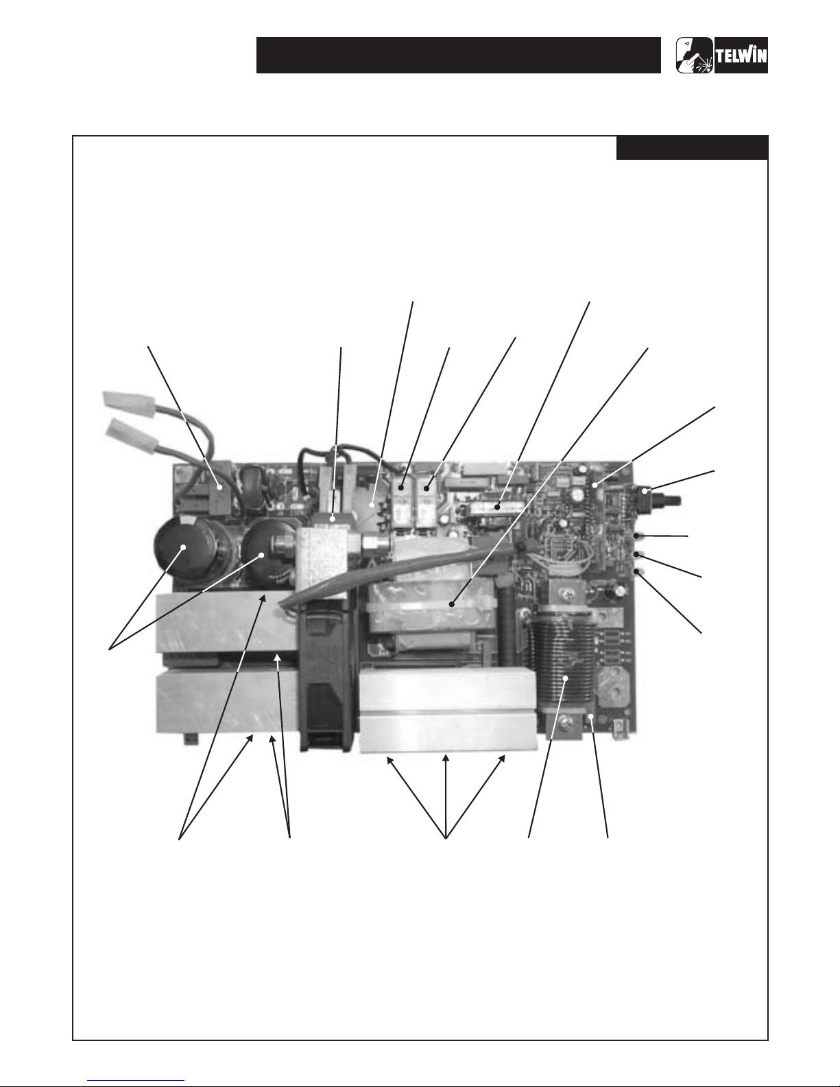
Power board
TECNICA PLASMA 18 - 31
(12)
DRIVER
(5)
CHOPPER
(31)
AIR
RELAY
(32)
AIR SOLENOID
VALV E
(3)
RECTIFIER
BRIDGE
(11)
FLY-BACK
POWER SUPPLY
PLASMA
CONTROL
BOARD
(4)
FILTER
(1)
EMC
FILTRE
PRIMARY
(7)
POWER
TRANSFORMER
(10)
SECONDARY
FILTER EMC
(8)
SECONDARY
DIODES
(2)
PRE-CHARGE
(18)
CURRENT
POTENTIOMETER
(26)
POWER
SUPPLY LED
(30)
TORCH
POWERED LED
(17)
ALARM
LED
(9)
INDUCTANCE
ILLUSTRATIONS
-6-
TECNICA PLASMA 18 - 31
TECNICA PLASMA 18 - 31
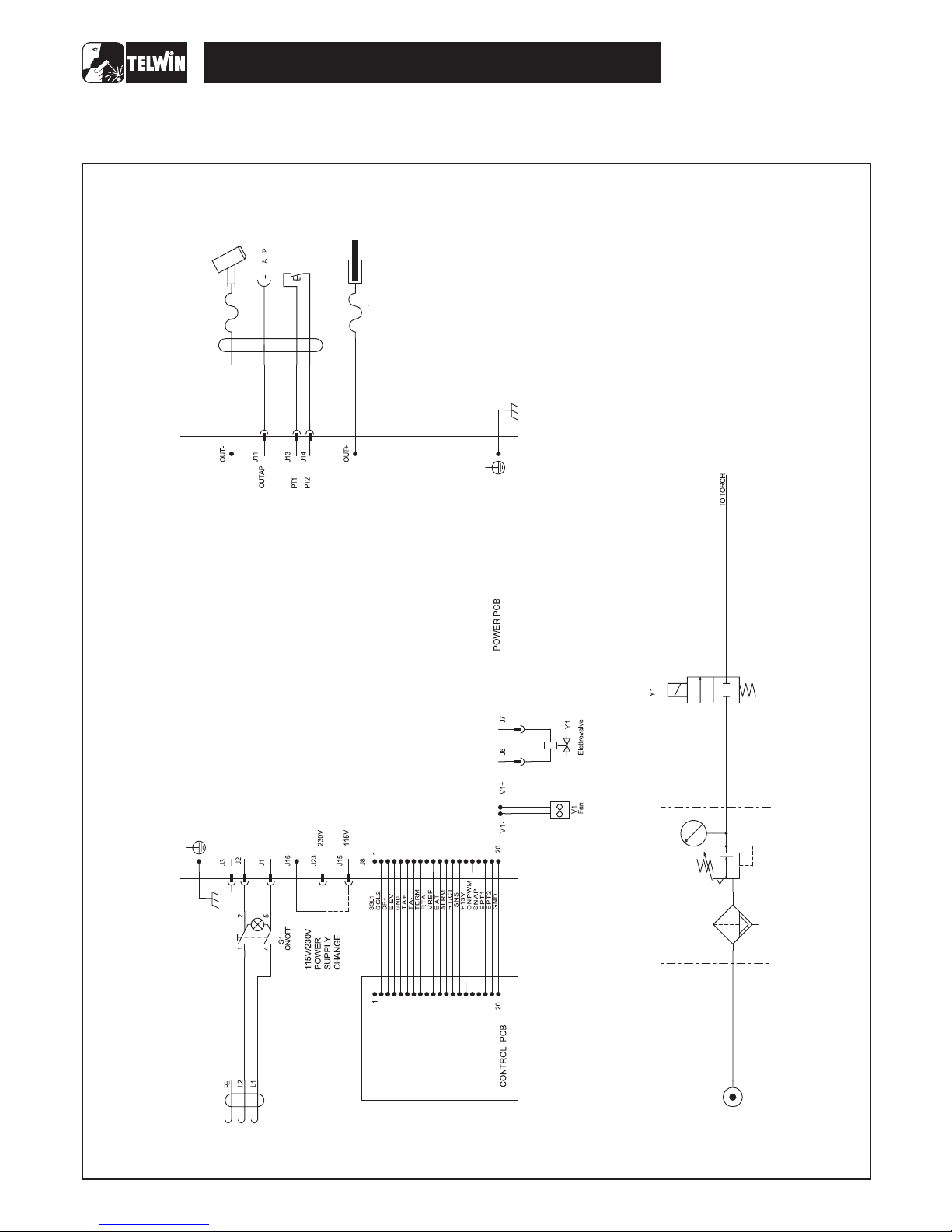
WIRING DIAGRAMS
General wiring diagram
 Loading...