

Telwin TECNICA144-164 Troubleshooting And Repair Manual

TECNICA 140.1 - 142
cod. 988637
inverter
TECNICA 144-164
CONTENTS PAGE
OPERATION AND WIRING DIAGRAMS................ 2
REPAIR GUIDE...................................................... 9
SPARE PARTS LIST...............................................18
REPAIR SHEET......................................................20
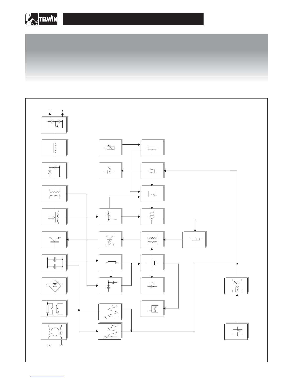
Block diagram 2
Analysis of the block diagram 3
Illustrations 5
Wiring diagrams 6
Equipment required 9
General repair instructions 10
Troubleshooting and remedies 10
Testing the machine 13
Illustrations 15
TROUBLESHOOTING
AND REPAIR MANUAL
TROUBLESHOOTING
AND
REPAIR MANUAL
TROUBLESHOOTING
AND REPAIR MANUAL
TROUBLESHOOTING
AND
REPAIR MANUAL
“reparation no problem !”
TECNICA 144 - 164
-2-
26
t
OVERVOLTAGE
PROTECTION
BLOCK DIAGRAM
OPERATION AND WIRING DIAGRAMSOPERATION AND WIRING DIAGRAMS
OPERATION AND WIRING DIAGRAMSOPERATION AND WIRING DIAGRAMS
6
1
7
22
CURRENT
POTENTIOMETER
25
11
ALIMENTATORE
FLY-BACK
13
15
SEPARATOR
TRANSFORMER
28
29
24
16
TRANSFORMER
PILOT
18
19
ADDER
20
ALARM CLOCK
2
3
4
5
8
8
9
17
14
10
12
AUXILIARY POWER
SUPPLYTRIGGER
11
VOLTAGE
RECTIFIER
21
27
t
23
OUTPUT
CURRENT
TRANSFORMER
INDUCTANCE
EMC FILTER II°
PRIMARY
EMC FILTER
POWER
TRANSFORMER
SECONDARY
DIODES
FILTER
CHOPPER
RECTIFIER BRIDGE
PRE-CHARGE
INPUT
FAN
POWER SUPPLY
LED
AUXILIARY POWER
SUPPLY
DRIVER
ALARM LED
PRIMARY CURRENT
READER AND LIMITER
MAXIMUM
CURRENT ADJUST.
DUTY CYCLE
MAKER
OVERVOLATGE
SEFEGUARD
THERMOSTATS
GALVANIC
SEPARATOR
POWER
TRANSFORMER
THERMOSTAT

-3-
ANALYSIS OF THE BLOCK DIAGRAM
NOTE: Unless indicated otherwise, it should be assumed that
the components areassembled on thepower board.
Consisting of: C1,T4, C8, C15.
Prevents noise from the machine from being transmitted along
the main powerline and vice versa.
Consisting of: PD1,R4.
Prevents the formation of high transitory currents that could
damage the main power switch, the rectifier bridge and the
electrolytic capacitors.
When the power source is switched on the relay PD1 is deenergised, capacitors C21, C22, C27 are then charged by R4.
When the capacitorsare charged the relayis energised.
Consisting of: PD1.
Converts the mains alternating voltage into continuous pulsed
voltage.
Consisting of: C21,C22, C27.
Converts the pulsed voltage from the rectifier bridge into
continuous voltage.
Consisting of: Q5,Q8.
Converts the continuous voltage from the filter into a high
frequency square wave capable of piloting the power
transformer.
Regulates the power according to the required welding
current/voltage.
Consisting of: T2.
The C.T. is used to measure the current circulating in the
power transformer primary and transmit the information to
block 17 (primarycurrent reader and limiter).
Consisting of: T3.
Adjusts the voltage and current to values required for the
welding procedure. Also forms galvanic separation of the
primary from the secondary (welding circuit from the power
supply line).
Consisting of: D32,D33, D34 .
D34 converts the current circulating in the transformer to a
single direction, preventingsaturation of the nucleus.
D32, D33 recirculate the inductance output current (block 9)
when the IGBT's are not conducting, bypassing the power
transformer (block 7).
Block 1
Block 2
Block 3
Block 4
Block 5
Block 6
Block 7
Block 8
EMC Filter
Pre-charge
Rectifier bridge
Filter
Chopper
Current transformer
Power transformer
Secondary diodes
Block 9
Block 10
Block 17
Block 18
Inductance
Secondary EMC Filter
Primary current readerand limiter
Duty cycle maker
Consisting of: L1.
Levels the secondary board diodes’ output current making it
practically continuous.
Consisting of: C28, C33.
Prevents noise from the power source from being transmitted
through the weldingcables and vice versa.
Consisting of: D2, R25.
Reads the signal from block 6 (current transformer) and scales
it down so it can be processed and compared in blocks 18 and
19.
Consisting of: U1.
Processes the information from block 19 (adder) and block 17
(primary current reader and limiter) and produces a square
wave with variable duty cycle limiting the primary current to a
maximum pre-set valueunder all circumstances.
Block 11
Block 12
Block 13
Block 14
Block 15
Block 16
Voltagerectifier
Auxiliary power supplytrigger
Auxiliary power supply
Driver
Separator transformer
TransformerPilot
Consisting of: D11,C18.
Rectifies and filters the voltage from the tertiary winding of the
power transformer (block7).
Consisting of: R18,R35, C20.
Via the resistors, the power source supplies the necessary
voltage to powerblock 13 (power supply).
Consisting of: U3,C17.
Stabilises the voltage at 12Vdc for the power arriving from
block 12 (auxiliary power supply trigger) and from block 11
(voltage rectifier).
Consisting of: Q6,D19, D23, Q7, D27,D26
Picks up the signal arriving from block 15 (separator
transformer) and under the control of block 17 (transformer
pilot) adjusts itto suit piloting ofblock 5 (chopper).
Consisting of: T1.
Supplies two signals, which are separated galvanically from
one another, that will be sent to powerblock 14 (driver).
Consisting of: Q4,D20, D22, D24.
Amplifies the signal arriving from block 18 (duty cycle maker),
needed to pilotblock 15 (separator transformer).
TECNICA 144 - 164

-4-
Block 27
Block 28
Block 29
Power supply LED
Fan
Consisting of: D10.
Indicates when the power source is correctly powered and
ready for use.
Consisting of: V1.
Powered directly by block 13 (flyback transformer) and cools
the power components.
Undervoltage safeguard
Consisting of: R39, R64, U2B .
If the main supply voltage falls below the minimum allowed
value this safeguard triggers (a tolerance of approx. ±15% of
the power supply voltage is allowed: outside this range the
safeguard triggers).
Block 19
Block 20
Block 21
Block 22
Block 23
Block 24
Adder
Alarm Block
Alarm LED
Current potentiometer
Maximum current adjustment
Power transformer thermostat
Overvoltage safeguard
Consisting of: U2C.
Gathers all the information from block 17 (primary current
reader and limiter), from block 20 (alarms) and from block 22
(current potentiometer), and produces a signal with a suitable
voltage for processingby block 18 (duty cycle maker).
Consisting of: Q3,R43, R44, R38, R36
When an alarm is detected the power source output current is
drastically reduced by making direct adjustments to block 18
(duty cycle maker) and directly changing the reference signal
obtained from block22 (current potentiometer).
Consisting of: D12.
It is switchedon by block 20(alarms) in theevent of:
1) Triggering of thermostatic capsule/thermostat on power
transformer.
Triggering due to undervoltage.
3) Triggering due to overvoltage.
4) Short circuit at output (electrode holder clamp and earth
cable connected to one another or electrode stuck to piece
being welded).
Consisting of: R23.
This is used to set the reference voltage needed to adjust the
output current: when the potentiometer knob is turned the
cursor voltage varies, thus varying the current from the
minimum to themaximum value.
Consisting of: JP1,JP2, JP3.
Used to adjust the maximum cutting current to be supplied by
the power source.
Consisting of: ST1.
When the temperature of the power transformer is too high,
this safeguard is triggered. It is reset automatically after the
alarm condition hasceased.
Consisting of: R1,R5, R14, R19, R24,R29, U2A.
If the main supply voltage exceeds the maximum value this
safeguard triggers (a tolerance of approx. ±15% of the power
supply voltage is allowed: outside this range the safeguard
triggers).
2)
Consisting of: ISO1.
The signal arriving from blocks 24 (power transformer
thermostat) is separated galvanically and sent to block 20
(alarms) for detectionof a possible alarmevent.
Block 25
Block 26
Galvanic separation
TECNICA 144 - 164
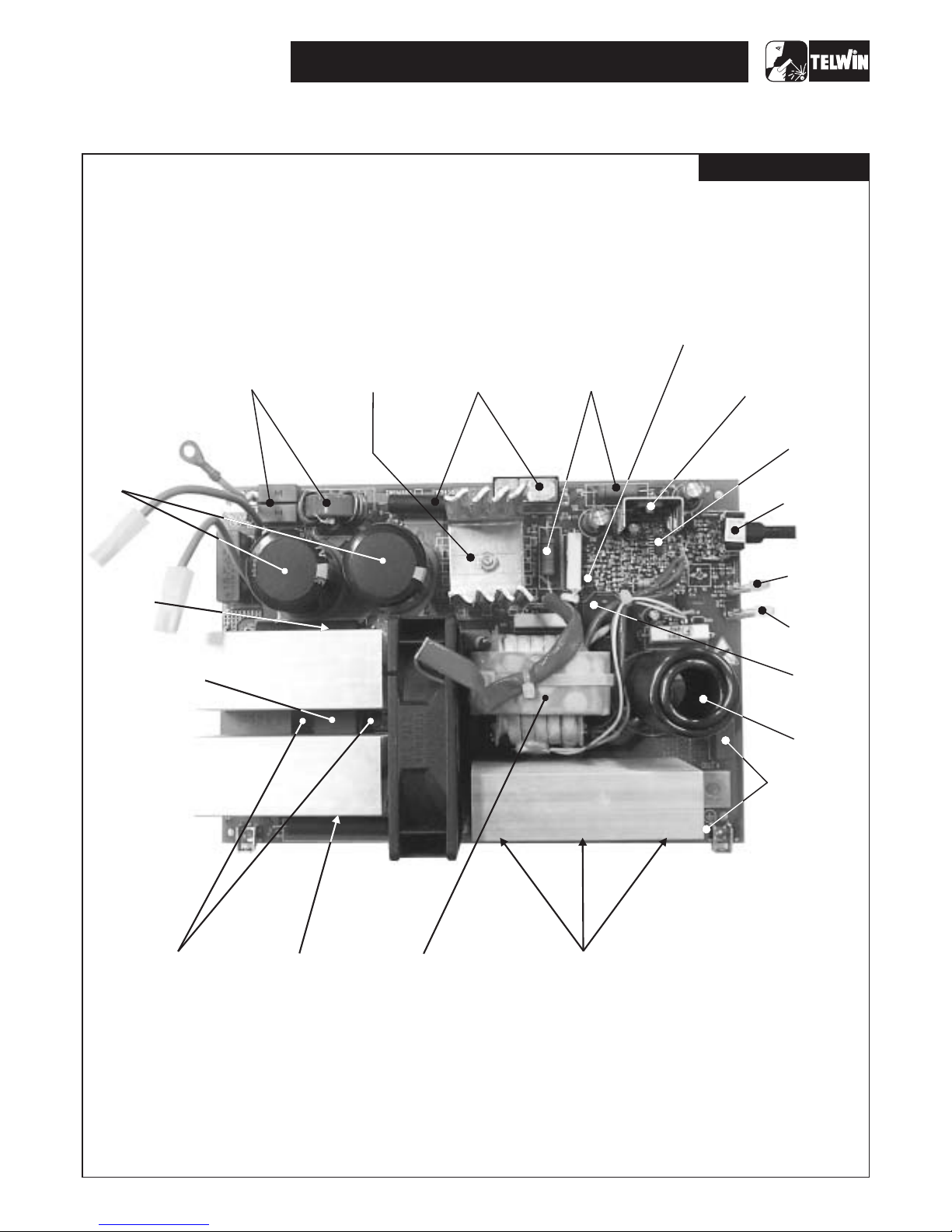
ILLUSTRATIONS
-5-
(5)
CHOPPER
(7)
POWER
TRANSFORMER
TECNICA 144 - 164
Power boad
(1)
PRIMARY EMC
FILTRE
(3)
RECTIFIER
BRIDGE
(2)
PRE-CHARGE
(6)
POWER
TRANSFORMER
(14)
DRIVER
(5)
CHOPPER
(4)
FILTER
(22)
CURRENT
POTENTIOM.
(15)
TRANSFORMER
SEPARATOR
(18)
DUTY CYCLE
MAKER
(10)
SECONDARY
FILTER EMC
(8)
SECONDARY
DIODES
(21)
ALARM
LED
(9)
INDUCTANCE
(12)
AUXILIARY POWER
SUPPLY TRIGGER
(28)
POWER
SUPPLY
LED
(19)
ADDER
(13)
AUXILIARY POWER
SUPPLY
-6-
TECNICA 144 - 164
POWER PCB
J3J3
J4-J4-
J2J2
PE
N (L2)
L1
PE
N (L2)
L1
OUT+OUT+
V1
Fan
OUT-OUT-
J1J1
J7J7
54
12
S1
ON/OFF
54
12
S1
ON/OFF
J4+J4+
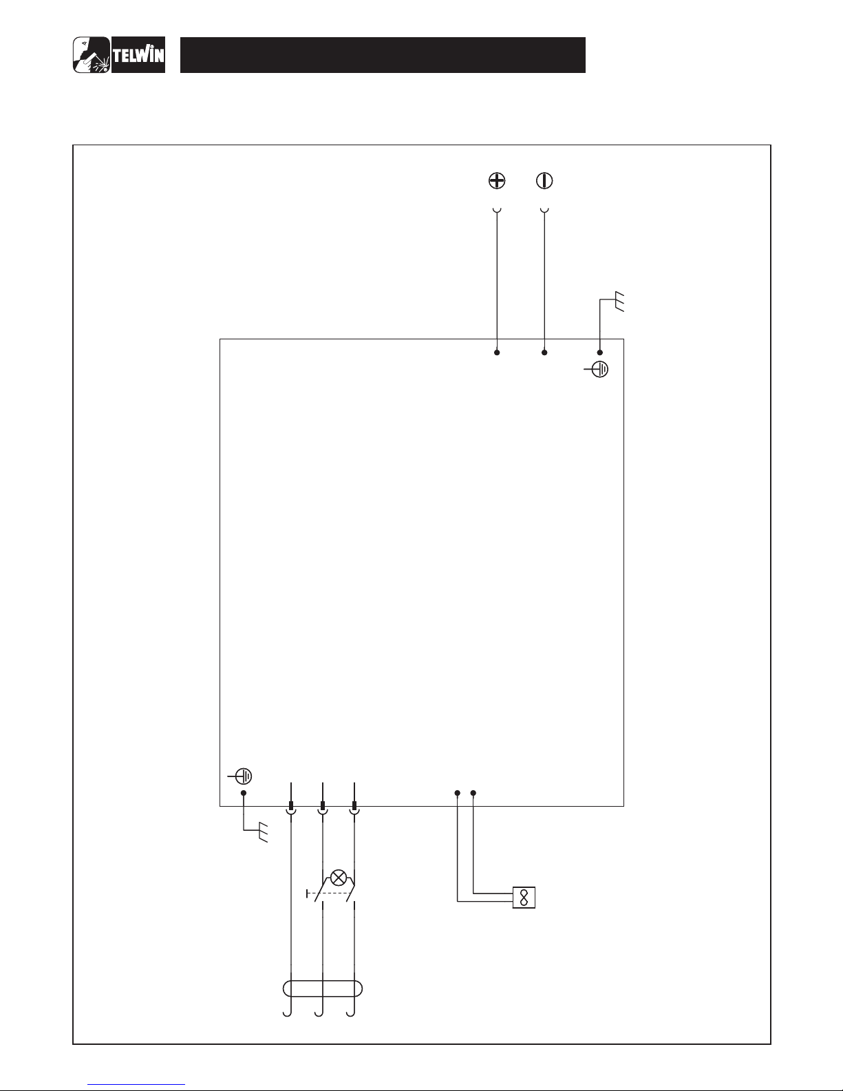
WIRING DIAGRAMS
General wiring diagram
-7-
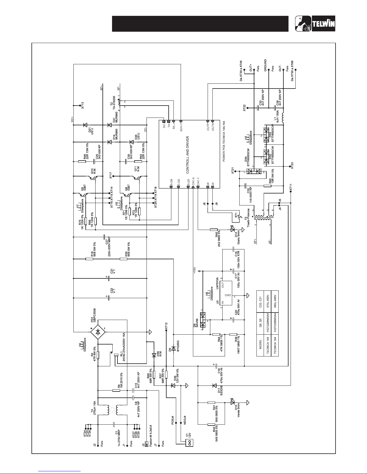
TECNICA 144 - 164
Wiring diagram power board – power supply
 Loading...