

Telwin TECNICA 1400, TECNICA 1600 Troubleshooting And Repair Manual
TROUBLESHOOTING
AND REPAIR MANUAL
TROUBLESHOOTING
AND REPAIR MANUAL
TEC
NICA
1
4
0
.1
- 1
4
2
“reparation no problem !”
cod. 988401
inverter
TEC
NIC
A 1400-1
600
CONTENTS PAG E
OPERATION AND ELECTRICAL DIAGRAMS................... 2
- Block diagram 2
- Analysis of block diagram 3
- Illustrations 5
- Electrical diagrams 6
REPAIR GUIDE.................................................................. 10
- Equipment required 10
- General repair instructions 11
- Troubleshooting and remedies 11
- Testing the machine 14
- Illustrations 16
SPARE PARTS LIST.......................................................... 17
REPAIR SHEET................................................................. 19
TROUBLESHOOTING
AND REPAIR MANUAL
TROUBLESHOOTING
AND REPAIR MANUAL
31/05/02

BLOCK DIAGRAM
TECNICA 1400 - 1600
- 2 -
26
25 12 13 14
19
20
24
232221
1 2 3 4 5 6 7 8 9 10 11
15 16 17
18
CONTROLLO
POWER INPUT
EMC FILTER
VARISTOR
RECTIFIER BRIDGEPRE-CHARGE
FILTER
CHOPPER
CURRENT
TRANSFORMER
TRANSFORMER SECONDARY
DIODES
INDUCTANCE
SECONDARY EMC
FILTER
OUTPUT
FAN
POWER
SUPPLY LED
FLY-BACK
POWER SUPPLY
DRIVER
CURRENT READER
ALARM LED
MAX CURRENT
ADJUSTMENT
DUTY CYCLE
MAKER
ADDER
ALARM BLOCK POTENTIOMETER
UNDERVOLTAGE
SAFEGUARD
POWER
TRANSFORMER
THERMOSTAT
GALVANIC
SEPARATOR
OVERVOLTAGE
AFEGUARD
OPERATION AND WIRING DIAGRAMSOPERATION AND WIRING DIAGRAMS
OPERATION AND WIRING DIAGRAMSOPERATION AND WIRING DIAGRAMS

- 3 -
ANALYSIS OF THE BLOCK DIAGRAM
NOTE: Unless indicated otherwise, it should be
assumed that the components are assembled on the
primary board.
Block 1
EMC Filter
Consisting of: C1, C5, C6, L1
Prevents noise from the machine from being
transmitted along the main power line and vice versa.
Block 2
Varistor
Consisting of: RV1
Prevents spike noise from the mains, with amplitude
greater than 400V , from entering the machine.
Block 3
Pre-charge
Consisting of: K1, R1
Prevents the formation of high transitory currents that
could damage the main power switch, the rectifier
bridge and the electrolytic capacitors.
When the power source is switched on the relay K1 is
de-energised, capacitors C2, C3, C4 are then
charged by R1. When the capacitors are charged the
relay is energised.
Block 4
Rectifier bridge
Consisting of: D1
Converts the mains alternating voltage into
continuous pulsed voltage.
Block 5
Filter
Consisting of: C2, C3, C4
Converts the pulsed voltage from the rectifier bridge
into continuous voltage.
Block 6
Chopper
Consisting of: Q1, Q2
Converts the continuous voltage from the filter into a
high frequency square wave (65 kHz approx.)
capable of piloting the power transformer.
Regulates the power according to the required
welding current/voltage.
Block 7
Current transformer
Consisting of: T2
The C.T. is used to measure the current circulating in
the power transformer primary and transmit the
information to block 14 (primary current reader).
TECNICA 1400 - 1600
Block 8
Power transformer
Consisting of: T3
Reduces the voltage converted by block 6 (chopper),
adjusting voltage and current to values required for
the welding procedure.
Also forms galvanic separation of primary from
secondary (welding circuit from the power supply
line).
Block 9
Secondary diodes
Consisting of: D21, D22, D23
D21 Eliminates the negative part of the secondary
voltage.
D22,D23 Recirculate the inductance output current
when the IGBT’s are not conducting.
Block 10
Reactance
Consisting of: L2
Levels the secondary board diodes’ output current
making it practically continuous.
Block 11
Secondary EMC Filter
Consisting of: C31, C32
Prevents noise from the power source from being
transmitted through the welding cables and vice
versa.
Block 12
Flyback power supply
Consisting of: T1, U2, U1
Uses switching methods to transform and stabilise
the voltage obtained from block 5 (filter) and supply 2
voltage values of 27V that enable b lock 13 (driver) to
be powered correctly. It also generates a further
stabilized voltage of 15V that is mainly used to power
the control board.
Block 13
Driver
Consisting of: ISO2, ISO3
T akes the signal from block 12 (flyback po wer supply)
and, controlled by block 15 (duty cycle maker),
makes the signal suitable for piloting block 6
(chopper).
Block 14
Primary current reader
Consisting of: R20, R37, R38 and part of the control
section.
Reads the signal from block 7 (current transformer)
and scales it down so it can be processed and
compared in blocks 15 and 16.

- 4 -
TECNICA 1400 - 1600
Block 15
Duty cycle maker
Consisting of: U2 (control board) = UC 3845
Processes the information from block 16 (adder) and
block 14 (primary current reader) and produces a
square wave with variable duty cycle limiting the
primary current to a maximum pre-set value under all
circumstances.
Block 16
Adder
Consisting of: U1D (control board)
Gathers all the information from block 14 (primary
current reader), from block 17 (alarms) and from
block 18 (potentiometer), and produces a signal with
a suitable voltage for processing by block 15 (duty
cycle maker).
Block 17
Alarm Block
Consisting of: U1A, U1C (control board)
When an alarm is detected the machine output
current is drastically reduced by directly adjusting
and changing the reference signal obtained from
block 18 (potentiometer).
Block 18
Potentiometer
Consisting of: R7
This is used to create the reference voltage needed to
adjust the output current: when the potentiometer is
turned the cursor voltage varies, thus varying the
current from the minimum to the maximum value.
Block 19
Yello w LED alarm light
Consisting of: D26 (yellow )
It is switched on by block 17 (alarms) in the ev ent of:
1) Triggering of thermostatic capsule on power
transformer.
2) T riggering due to undervoltage.
3) T riggering due to overvoltage.
4) Short circuit at output (electrode holder and earth
cable connected to each other or electrode stuck
to piece being welded).
Block 20
Maximum current adjustment
Consisting of: R32, R33, R42
Used to adjust the maximum welding current
supplied by the power source.
Block 21
Power transformer thermostat
Consisting of: ST1 thermostatic capsule.
When the temperature of the power transformer is
too high, this safeguard is triggered. It is reset
automatically after the alarm condition has ceased.
Block 22
Galvanic separator
Consisting of: ISO1
The signal from the thermostatic capsules is
separated galvanically and sent to block 17 (alarms)
for identification of possible alarm condition.
Block 23
Overvoltage safeguard
Consisting of: R3, R4 and part of the control section
If the main supply voltage exceeds the maximum
value this safeguard triggers (a tolerance of approx.
±15% of the power supply voltage is allowed: outside
this range the safeguard triggers).
Block 24
Undervoltage safeguard
Consisting of: R5, R6 and part of control board
If the main supply voltage falls below the minimum
allowed value this safeguard triggers (a tolerance of
approx. ±15 % of the power supply voltage is allowed:
outside this range the safeguard triggers).
Block 25
Power supply LED
Consisting of: D2
Shows that the machine is correctly powered and
ready to weld.
On machines operating exclusively at 230V it is
green.
Block 26
Fan
Cools the power components. On machines
operating exclusively at 230V it is powered directly b y
block 12 (at 12V).
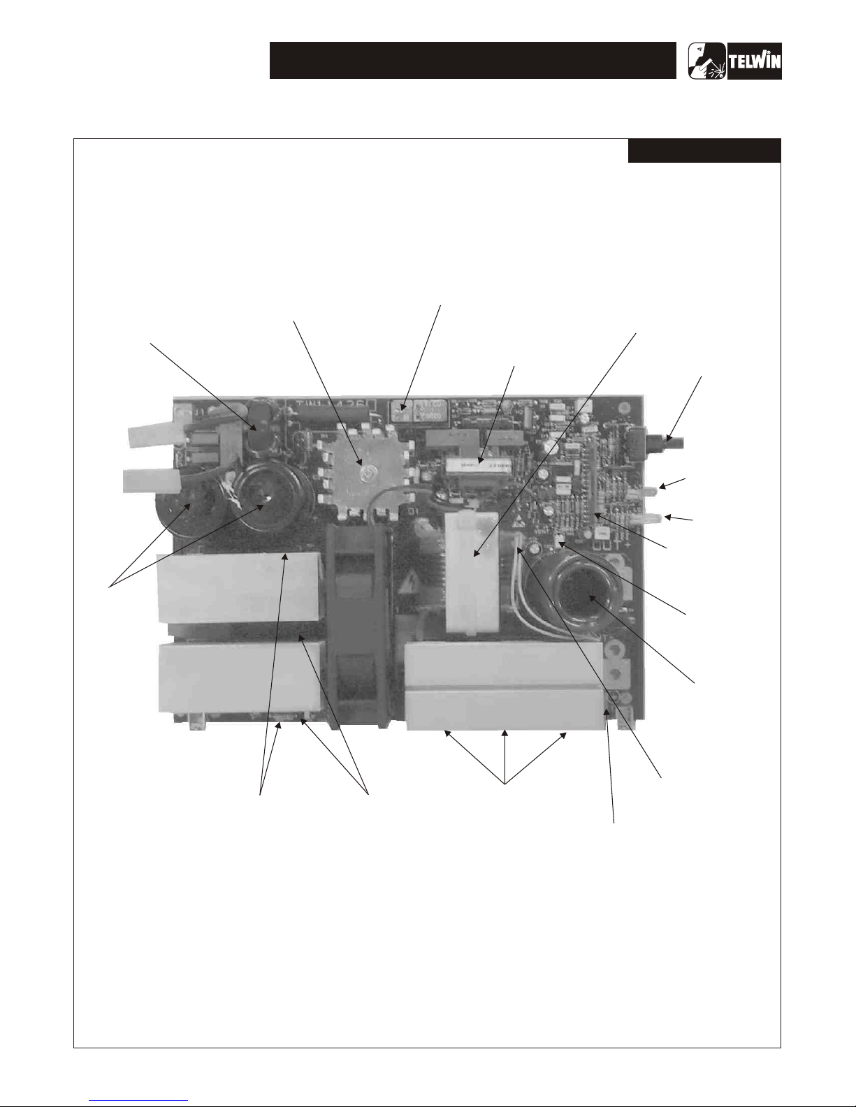
ILLUSTRATIONS
TECNICA 1400 - 1600
- 5 -
1
EMC FILTER
3
RECTIFIER BRIDGE
4
PRE-CHARGE
12
FLY-BACK
TRANSFORMER
8
POWER TRANSFORMER
18
POTENTIOMETER
25
POWER
SUPPLY LED
19
ALARM LED
15 DUTY CYCLE
MAKER
22
GALVANIC
SEPARATOR
10
INDUCTANCE
21
THERMOSTATIC
CAPSULE
ON POWER
TRANSFORMER
11
SECONDARY
EMC FILTER
9
SECONDARY
DIODES
5
FILTER
6
CHOPPER
13
DRIVER
Power board
TECNICA 1400 - 1600
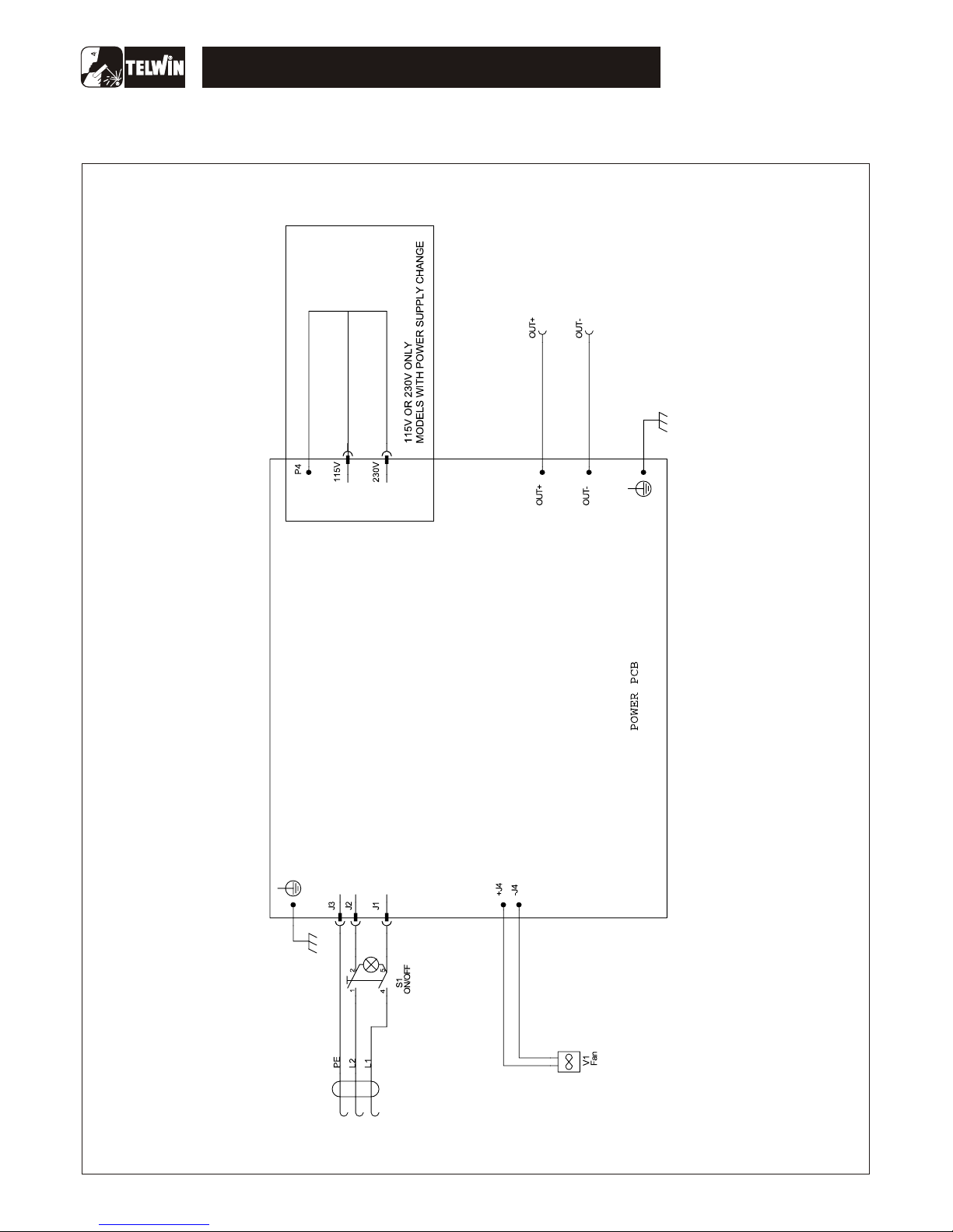
General wiring diagram – TECNICA 1400 – 1600
- 6 -
WIRING DIAGRAM
 Loading...