

cod. 988656
TECNICA 114
TECNICA 140.1 - 142
inverter
TROUBLESHOOTING
TROUBLESHOOTING
TROUBLESHOOTING
TROUBLESHOOTING
AND REPAIR MANUAL
AND
AND REPAIR MANUAL
AND REPAIR MANUAL
CONTENTS PAGE
OPERATION AND WIRING DIAGRAMS................ 2
Block diagram 2
Analysis of the block diagram 3
Illustrations 5
Wiring diagrams 6
REPAIR GUIDE...................................................... 9
Equipment required 9
General repair instructions 10
Troubleshooting and remedies 10
Testing the machine 13
Illustrations 15
REPAIR MANUAL
SPARE PARTS LIST...............................................17
REPAIR SHEET......................................................19
“reparation no problem !”
TECNICA 114
OPERATION AND WIRING DIAGRAMSOPERATION AND WIRING DIAGRAMS
OPERATION AND WIRING DIAGRAMSOPERATION AND WIRING DIAGRAMS
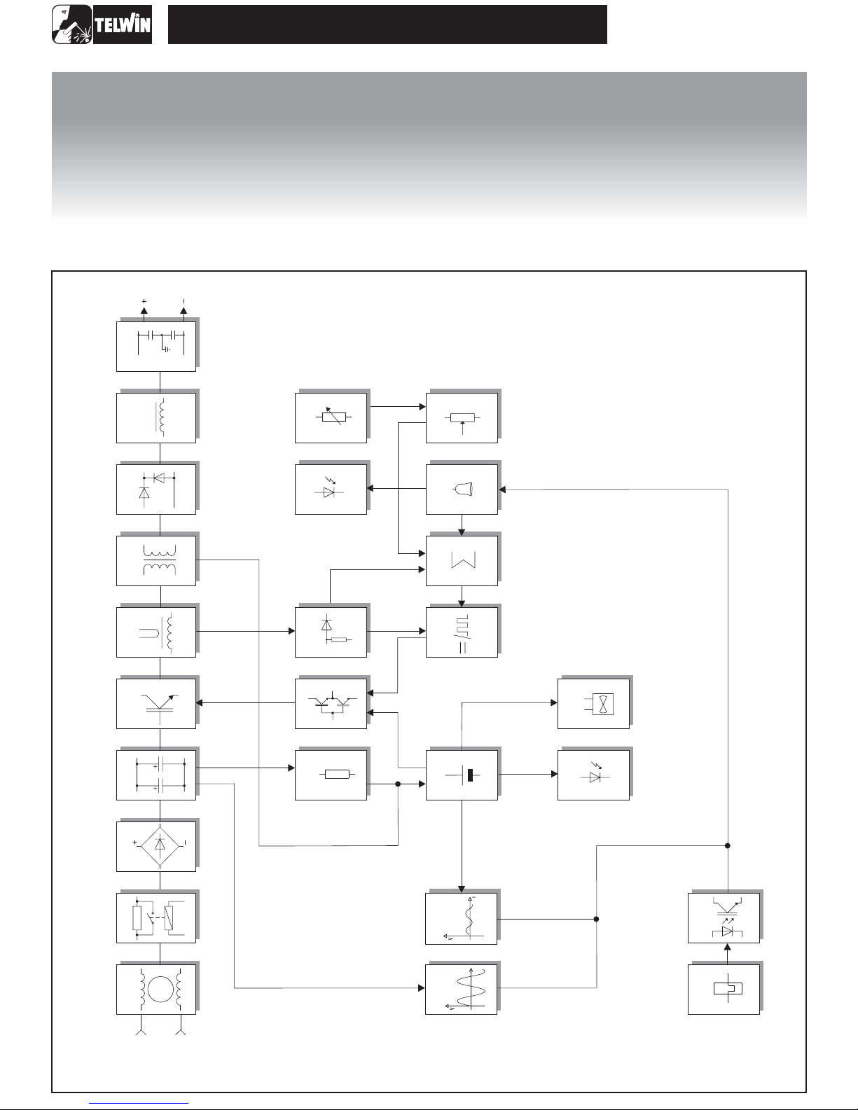
BLOCK DIAGRAM
OUTPUT
SECONDARYEMC
FILTER
10
INDUCTANCE
SECONDARY
DIODE
POWER
TRANSFORMER
CURRENT
TRANSFORMER
CHOPPER
FILTER
9
8
8
7
6
5
4
MAXIMUM
CURRENT
ADJUSTMENT
ALARM LED
PRIMARY
CURRENT READER
DRIVER
AUXILIARY POWER
SUPPLYTRIGGER
CURRENT
20
18
AND LIMITER
14
13
11
POTENTIOMETER
ALARM BLOCK
ADDER
DUTY CYCLE MAKER
AUXILIARY
POWER
SUPPLY
ALIMENTATORE
FLY-BACK
19
17
16
15
FAN
POWER
11
12
SUPPLYLED
26
25
RECTIFIER BRIDGE
PRE-CHARGE
EMC FILTER
INPUT
3
2
1
-2-
UNDERVOLTAGE
SAFEGUARD
OVERVOLTAGE
SAFEGUARD
GALVANIC
24
t
23
SEPARATION
IGBT THERMOSTAT
22
21

TECNICA 114
ANALYSIS OFTHE BLOCK DIAGRAM
NOTE: Unless indicated otherwise, it should be assumed
thatthecomponentsare assembledonthepowerboard.
Block 1
EMC Filter
Consistingof:C1,C8,C9,L1.
Prevents noise from the machine from being transmitted
alongthemainpowerlineandviceversa.
Block 2
Pre-charge
Consistingof:K1,R2.
Preventstheformation of high transitory currents that could
damage the main power switch, therectifier bridge and the
electrolyticcapacitors.
When the power source is switched on the relay K1 is deenergised, capacitors C2, C3, C4 are then charged by R2.
Whenthecapacitorsare chargedtherelayisenergised.
Block 3
Rectifier bridge
Consistingof:D1.
Converts the mains alternating voltage into continuous
pulsedvoltage.
Block 9
Inductance
Consistingof:L2.
Levelsthe secondaryboarddiodes’output current makingit
practicallycontinuous.
Block 10
Secondary EMC Filter
Consistingof: C23,C24.
Prevents noise from the power source from being
transmittedthroughtheweldingcablesandviceversa.
Block 11
Auxiliary power supplytrigger
Consistingof:R13,R14,R15,C13
Via the resistors, the power source supplies the necessary
voltagetopowerblock12(auxiliarypowersupply).
Block 12
Auxiliary power supply
Consistingof:D10,C11,Q11,D11
Rectifies, filters and stabilises the voltage arriving from the
tertiarywindingofthe powertransformer(block7).
Block 4
Filter
Consistingof:C2,C3,C4.
Converts the pulsed voltage from the rectifier bridge into
continuousvoltage.
Block 5
Chopper
Consistingof:Q1.
Converts the continuous voltage from the filter into a high
frequency square wave capable of piloting the power
transformer.
Regulates the power according to the required welding
current/voltage.
Block 6
Current transformer
Consistingof:T2.
The C.T. is used to measure the current circulating in the
power transformer primary and transmit the information to
block17 (primarycurrentreaderandlimiter).
Block 7
Powertransformer
Consistingof:T1.
Adjusts the voltage and current to values required for the
welding procedure. Also forms galvanic separation of the
primary fromthesecondary (weldingcircuitfrom the power
supplyline).
Block 13
Driver
Consistingof:Q6,Q7,D46,D47
Picksupthesignalarrivingfromblock 15 (duty cycle maker)
adjustsittosuit pilotingofblock5 (chopper).
Block 14
Primary current reader and limiter
Consistingof: D42,D45,R56,C44,R57, R58,R59.
Reads the signal from block 6 (current transformer) and
scales it down so it can be processed and compared in
blocks15 and16.
Block 15
Duty cycle maker
Consistingof:U3,U2B.
Processes the information from block 16 (adder) and block
14 (primary current reader and limiter) and produces a
square wave with variable duty cycle limiting the primary
current to a maximum pre-set value under all
circumstances.
Block 16
Adder
Consistingof:U1D.
Gathers all the information from block 14 (primary current
reader and limiter), from block 17 (alarms) and from block
19 (current potentiometer), and produces a signal with a
suitable voltage for processing by block 15 (duty cycle
maker).
Block 8
Secondary diode
Consistingof:D22
Diode D22 converts the current circulating in the
transformer to a single direction, preventing saturation of
the nucleus, and recirculates theinductance output current
(block 9) during the time when the IGBT's are not
conducting,bypassingthe powertransformer(block7).
Block 17
Alarm Block
Consistingof:Q3,U1A,U1C.
Whenanalarm is detectedthepowersourceoutputcurrent
isdrasticallyreduced bymaking direct adjustments to block
15 (duty cycle maker) and directly changing the reference
signalobtainedfromblock19(currentpotentiometer).
-3-

TECNICA 114
Block 18
Alarm LED
Consistingof:D35.
Itisswitchedonbyblock17(alarms)inthe eventof:
1) Triggering of thermostatic capsule/thermostat on power
transformer.
2) Triggeringofthermostaticcapsuleonsecondarydiodes.
3) Triggeringduetoovervoltage.
4) Short circuit at output (electrodeholder clamp and earth
cable connected to one another or electrode stuck to
piecebeingwelded).
Block 19
Current potentiometer
Consistingof:R75.
This is used to set the reference voltage needed to adjust
the output current: when the potentiometer knob is turned
the cursor voltage varies, thus varying the current from the
minimumtothemaximumvalue.
Block 20
Maximum current adjustment
Consistingof:R70,R71,R72,R73,R74.
Used to adjust the maximum cutting current to be supplied
bythepowersource.
Block 21
IGBT Thermostat
Consistingof:ST1
When the temperature of the IGBT dissipator reaches a
giventemperaturethethermostatcuts in, sending an alarm
signal to block 22 (galvanic separation). It is reset
automatically when this alarm condition is no longer
present.
Block 26
Fan
Consistingof:V1.
Powered directly by block 12 (a ) and
coolsthepowercomponents.
uxiliary power supply
Block 22
Galvanic separation
Consistingof:ISO1
The signal arriving from blocks 21 (IGBT thermostat) is
separated galvanically and sent to block 17 (alarms) for
detectionofapossiblealarmevent.
Block 23
Overvoltage safeguard
Consistingof:R40,R41,R42,Q3.
If the main supplyvoltageexceedsthe maximum valuethis
safeguard triggers (a tolerance of approx. ±15% of the
power supply voltage is allowed: outside this range the
safeguardtriggers).
Block 24
Undervoltage safeguard
Consisting of: R63, R64, U1C, Q8.
If the main supply voltage falls below the minimum
allowed
value this safeguard triggers (a tolerance of approx.
±15% of the power supply voltage is allowed:outside this
range the safeguard triggers).
Block 25
Powersupply LED
Consistingof:D34.
Indicates when the power source is correctly powered and
readyforuse.
-4-
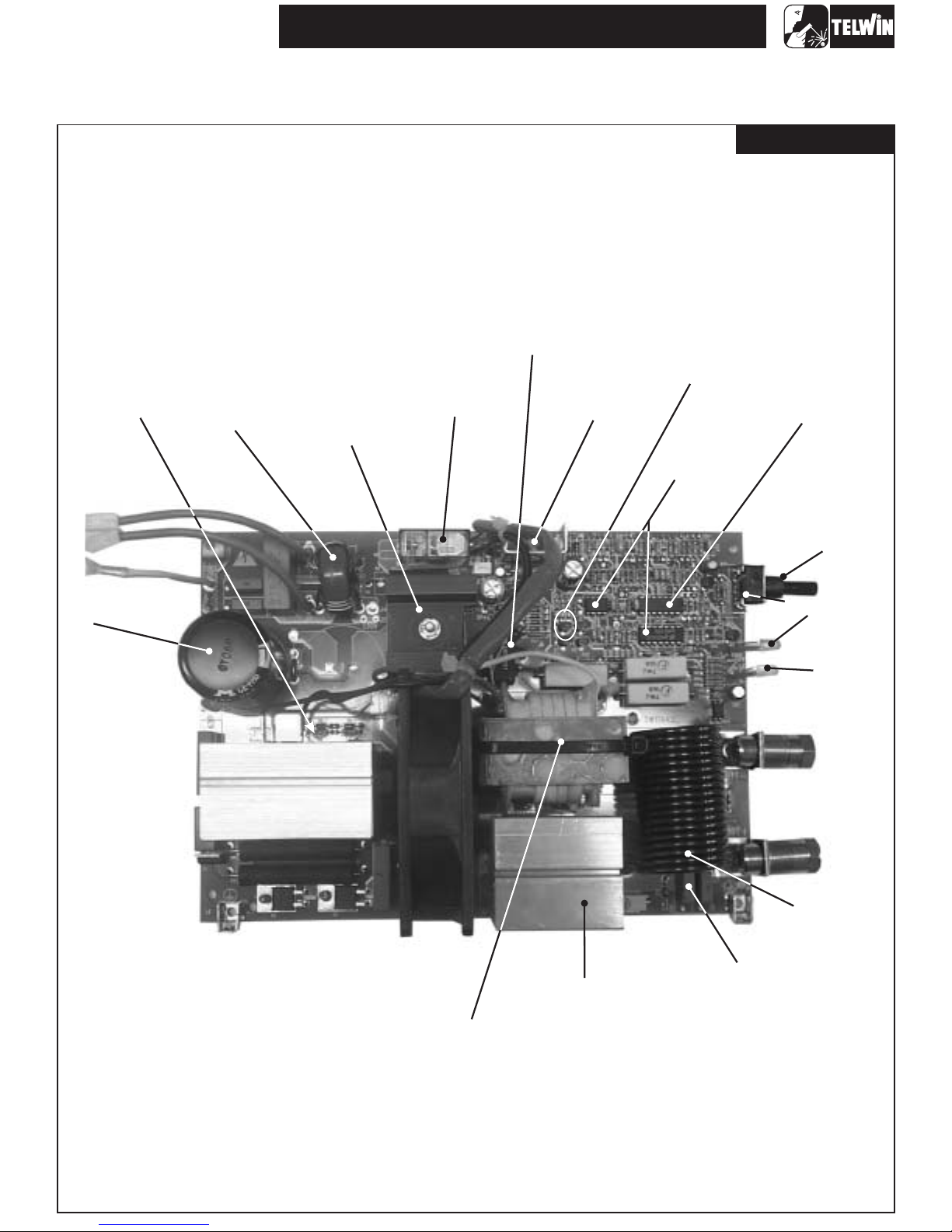
ILLUSTRATIONS
(5)
CHOPPER
EMC FILTER
(1)
(3)
RECTIFIER
BRIDGE
TECNICA 114
(6)
CURRENT
TRANSFORMER
(2)
PRE-CHARGE
AUXILIARY POWER
(12)
SUPPLY
(13)
DRIVER
(15)
DUTY CYCLE
MAKER
Power boad
(16)
ADDER
(17)
ALARM BLOCK
(4)
FILTER
(19)
CURRENT
POTENTIOMETER
(25)
POWER
SUPPLY LED
(18)
ALARM
LED
(9)
INDUCTANCE
(7)
POWER
TRANSFORMER
-5-
(8)
SECONDARY
DIODE
(10)
SECONDARY
EMC FILTER
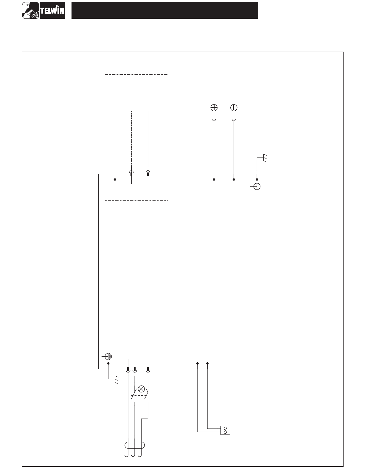
WIRING DIAGRAMS
General wiring diagram
TECNICA 114
100/115V OR 230V ON L Y
MODELS WITH POWER SUPPLY CHANGE
P4P4
115V115V
230V230V
OUT+OUT+
OUT-OUT-
POWER PCB
J7J7
-J4-J4
-6-
+J4+J4
V1
FanV1Fan
J1J1
J2J2
J3J3
5
5
2
2
S1
S1
4
4
1
1
N (L2)
L1
PE
ON/OFF
ON/OFF
 Loading...