

Teltronic U PTRNKTMBS760 User Manual
PRODUCT: MBS
CLASSIFICATION:
MBS USE R AN D INSTALLATION MANUAL
CODE:
VERSION:
D148X01PT_DDS06
04
REVISION:
00
DATE:
General information Internal document
DOCUMENT MAINTENANCE
THIS DOCUMENT HAS 17 PAGES
EDIT. DATE AUTHOR DESCRIPTION
1.0 05-Oct-2011 Javier Córdova First edition.
2.0 02-May-2012 Javier Córdova
3.0 19-Dec-2012 A. González
4.0 14-Nov-2014 F.Rivas New chapters added
Changes in section 4.
Document code and minor editorial changes.
Addition of labelling information and FCC RF
Exposure Requirements.
14-Nov-2014
ACTIVITY NAME DATE SIGNATURE
Project Manager
R&D Director
01.01.00/1 Rev.1
DOCUMENT APPROVAL
Prepared
Revised
Approved

MBS USER AND
Code: D148X01PT_DDS06
INSTALLATION
MANUAL
PowerTrunk Inc. is the subsidiary of Teltronic S.A.U. responsible for business development, distribution and
customer support for Teltronic’s Land Mobil e Radi o products in North America. The company is headquartered in
New York City. Teltronic S.A.U. distributes the same products for Land Mobile Radio under different trademarks
and brand names in other regions of the world.
Disclaimer
Although every reasonable effort has been made to ensure the accuracy of the information contained herein and
any other referred document, this should not be construed as a commitment on the part of Teltronic S.A.U.
and/or PowerTrunk Inc., and the liability of Teltronic S.A.U. and/or PowerTrunk Inc. for any errors and omissions
shall be limited to the correction of such errors and omissions. Teltronic S.A.U. and/or PowerTrunk Inc.
welcomes any comment as a way to improve any delivered documentation.
The information contained herein has been prepared for the use of appropriately trained personnel, and it is
intended for the purpose of the agreement under which the information is submitted. Any party using or relying
upon this information assumes full responsibility for such use and in no event shall Teltronic S.A.U. and/or
PowerTrunk Inc. be liable to anyone for especial, collateral, incidental, or consequential damages in connection
with or arising out of the use of this information.
Date: 14-Nov-2014 Page: 2 of 41
The information or statements given in these documents regarding the suitability, capacity or performance of the
mentioned hardware or software products cannot be considered binding but shall be defined in the agreement
made between Teltronic S.A.U. and/or PowerTrunk Inc. and the customer.
Teltronic S.A.U. and/or PowerTrunk Inc. reserves the right to revise these documents and to make changes to its
content at any time, without prior notification.
Copyrights
No part of the information contained herein and the other referred documents may be copied, distributed or
transmitted by any means to any other party without prior written permission of Teltronic S.A.U. and/or
PowerTrunk Inc. The distribution of this document may be also covered by NDA (non-disclosure agreement)
between Teltronic S.A.U. and/or PowerTrunk Inc. and the receiver.
Please also note that part of these contents even may be covered by patent rights.
This document, the referred documents and the described product are considered protected by copyright
according to the applicable laws.
PowerTrunk and the PowerTrunk logo are registered trademarks of Teltronic S.A.U.
Copyright © PowerTrunk Inc. All rights reserved
01.01.00/1 Rev.1

MBS USER AND
Code: D148X01PT_DDS06
INSTALLATION
MANUAL
CONTENTS:
1. INTRODUCTION ......................................................................................................... 4
2. UNPACKIN G AND CHECKING .................................................................................. 4
3. PREVIOUS CONSI DERATIONS................................................................................. 4
4. LABELLING AND INFORMATION ON SAFETY AND ELECTROMAGNETIC
COMPATIBILITY .................................................................................................................. 5
4.1. STANDARDS .......................................................................................................... 7
4.2. UL / SAFETY CERTIFICA TIONS ............................................................................ 8
4.3. MECHANICA L AND ENVIRONMENTA L STANDARDS ......................................... 8
4.3.1. STANDARDS CENELEC ................................................................................... 8
4.3.2. STANDARD S MIL-STD 810G ............................................................................ 9
Date: 14-Nov-2014 Page: 3 of 41
5. EQUIPMENT DESCRIPTION .................................................................................... 11
5.1. VIEW...................................................................................................................... 11
5.2. CONNECTORS ..................................................................................................... 12
5.3. VISUAL INDICATORS ........................................................................................... 13
5.4. DIMENSIONS ........................................................................................................ 14
6. INSTALLATION GUIDE ............................................................................................ 14
6.1. NECESSARY EQUIPMENT ................................................................................... 16
6.2. BASIC PRE-CONFIGURA TION ............................................................................ 18
6.3. INSTALLATION ..................................................................................................... 19
6.3.1. MAST/POLE INSTALLATION .......................................................................... 20
6.3.2. WALL INSTALLATION .................................................................................... 25
6.3.3. ANTI -VANDAL KIT INSTALLATION ................................................................ 28
6.3.4. CONNECTIONS .............................................................................................. 30
7. START UP/CONFIGURA TION/VERIFI CATION ....................................................... 40
8. INCIDENTS ............................................................................................................... 41
8.1. INTERFEREN CE AT MBS UNIT ........................................................................... 41
8.2. OVER VOLTAGE PROTECTION .......................................................................... 41
01.01.00/1 Rev.1
MBS USER AND
Code: D148X01PT_DDS06
INSTALLATION
MANUAL
1. INTRODUCTION
The MBS Units are the outdoor modules that make up a Mast Mounted Base Station (MBS).
They are independent units that can be interconnected with each other to increase the base
station capacity. A MBS consists of a maximum of two MBS Units.
This manual is common to all the equipment models, including all their options and
accessories.
The proper operation of any electronic device depends on its correct use. Therefore, it is
recommended to follow the instructions showe d in this manual.
2. UNPACKING AND CHECKING
The equipment is supplied with all the necessary materials for the installation, either on a
mast/pole or on a wall:
Date: 14-Nov-2014 Page: 4 of 41
q MBS Unit includes the followings items
§ One power connector.
§ One Ethernet connector
§ RF super-flexible wire N-Male – N-Male.
q Brackets for the installation.
Besides, in some types of installation, as detailed below, it is necessary an additional
material that is NOT supplied with the equipment.
IMPORTANT: If any of the necessary elements to carry out the installation process
described in this guide is missing or damaged, please contact your supplier.
3. PREVIOUS CONSIDERATIONS
This manual contains information about instructions for installation, maintenance and use.
Read the following pages before using this equipment.
It is not advisable to switch on the equipment without having previously connected the
antenna otherwise irreparable damage could be. It is important to use an antenna adjusted
to the work freque ncy.
01.01.00/1 Rev.1
MBS USER AND
Code: D148X01PT_DDS06
INSTALLATION
MANUAL
4. LABELLING AND INFORMATION ON SAFETY AND ELECTROMAGNETIC
COMPATIBILITY
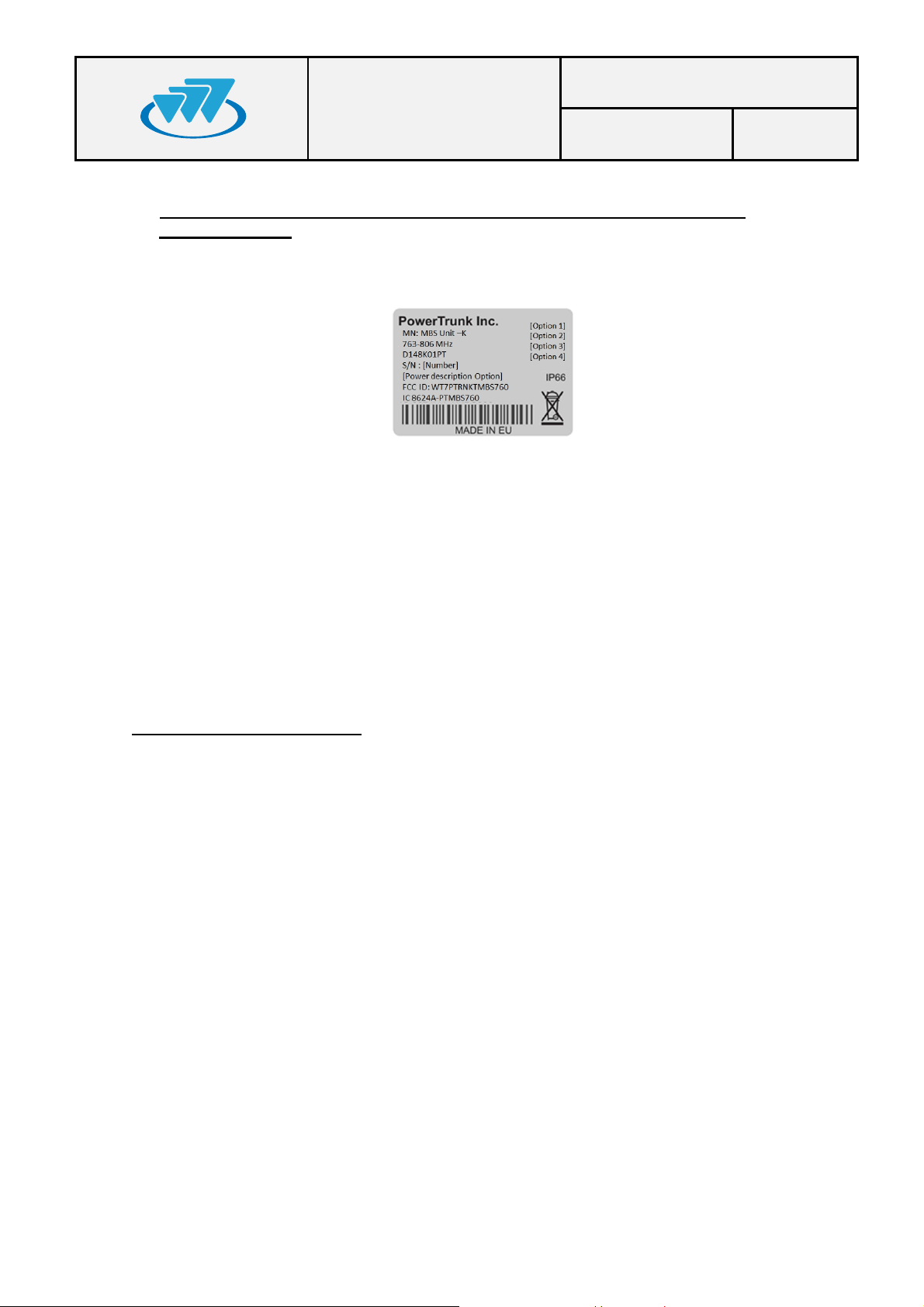
The equipment is supplied with an identification label where the model, the IC
Certificate number and the FCC ID are displayed de pending on the frequency work band.
The equipment has been designed to fulfil the applicable compliance regulations.
The equipment complies with the applicable Parts of the FCC Title 47 of the Code of
Federal Regulations and Industry Canada (IC) RSS-119 Standard.
Date: 14-Nov-2014 Page: 5 of 41
This device complies with part 15 of the FCC Rules and Industry Canada ICES-003.
Operation is subject to the following two conditions: (1) this device may not cause
interference, and (2) this device must accept any interference, including interference that
may cause undesired operation of the device.
Changes or modifications not expressly approved by the party responsible for
complia nce could void the user's authority to operate the equipm ent.
RF Exposure Requirements:
CAUTION:
The antenna(s) used for this transmitter must not be co-located or operating in
conjunction with any other antenna or transmitter.
Antennas used for this transmitter must not exceed an antenna gain of 20 dBi and
be located at least 400 cm, away from any person(s) in order to comply with the FCC and
IC RF exposure requirements.
Failure to observe these restrictions will result in exceeding the RF exposure limits.
01.01.00/1 Rev.1
MBS USER AND
Code: D148X01PT_DDS06
INSTALLATION
MANUAL
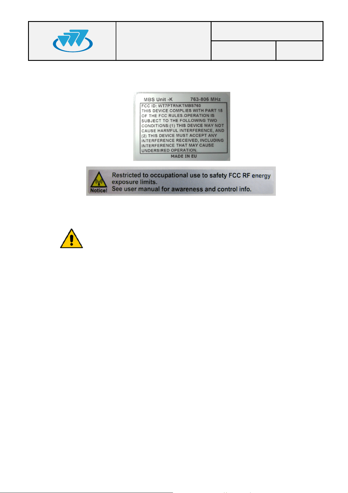
The following labels will be placed in conspicuous view on the MBS Unit:
Date: 14-Nov-2014 Page: 6 of 41
q Most electronic equipment is susceptible to electromagnetic
interference if it is not duly protected. If the MBS Unit is placed near
unprotected electr onic devices, they may malfunction.
q The MBS Unit must not transmit without its antenna connected.
q When installing the antenna, follow the guidelines for exposure of the
human body to high and low frequency electromagnetic fields. Follow
the supplier’s / manufacturer’s instructions.
q Burns may be suffered if the antenna connector output is touched by
bare skin when the MBS Unit is transmitting with the antenna
disconnected.
q Take care when handling the MBS Unit. It has edges, which may cut if
handled incorrectly.
q Maintenance and repair of these repeaters must be carried out by
qualified personnel only.
01.01.00/1 Rev.1
MBS USER AND
Code: D148X01PT_DDS06
INSTALLATION
MANUAL
4.1.STANDARDS
The equipment has been de signed according to the following standards:
Date: 14-Nov-2014 Page: 7 of 41
ETSI EN 300 394-1
ETSI EN 301 489-1
ETSI EN 301 489-18
EN 60950-1 / IEC 60950-1 / UL 60950-1 /
CSA 6095 0- 1
EN 60950-22 / IEC 60950-22 / UL 60950-22
/ CSA 60950-22
EN 60215 Safety requirements for radio transm itting equipment
EN 50383
EN 50385
EN 50121-4
Terrestrial Trunked Radio (TETRA);Conformance
testing specification; Part 1: Radio
Electromagnetic Compatibility and Radio spectrum
Matters (ERM); ElectroMagnetic Compatibility (EMC)
standar d for radio equipment and services; Part 1:
Common t echnical requirements
Electromagnetic Compatibility and Radio spectrum
Matters (ERM); ElectroMagnetic Compatibility (EMC)
standar d for radio equipment and services; Part 18:
Speci fic conditions for TETRA equipment
Information technology equipment - Safety -- Part 1:
General requirements
Information technology equipment - Safety -- Part 22:
Equipment to be ins talled outdoors
Basic standard for the calculation and measurement
of electromagnetic field strength and SAR related to
human exposure from radio base stations an d fixed
terminal stations for wireless t elecommunication
systems (110 MHz - 40 GHz)
Product standard to demonstrate the compliance of
radio bas e stations and fixed terminal stations for
wireless telecommunication systems with the basic
restrictions or the reference levels related to human
exposure to radio fr equency electromagn etic fields
(110 MHz - 40 GHz) - General public
Railway applications - Electromagnetic compatibility Part 4: Em ission and imm unity of the signalling and
telecomm unications ap paratus
These standards ensure the essential requirements set out in Article 3 of Directive
1999/5/EC.
01.01.00/1 Rev.1
MBS USER AND
Code: D148X01PT_DDS06
INSTALLATION
MANUAL
4.2.UL / SAFETY CERTIFICATIONS
The cabinet is UL certified, and complies with the requirements for
electronic dev ices to m inimise ri sks such as f ire, electric shocks or inj uries to the
operator that may be caused in operation. File number is the following: E318948
MBS Unit complies with the standard UL 60950-1 y UL 60950-22,
including the National Differences for United States, Canada and CENELEC
(Europe), and it has CB Test Certificate
4.3.MECHANICAL AND ENVIRONMENTAL STANDARDS
Date: 14-Nov-2014 Page: 8 of 41
The equipment complies with the following standards:
4.3.1. STANDARDS CENELEC
EN 60068-2-1
* No Functional. -40 ºC. Duration: 72 h
Environmental testing -- Part 2-1: Tests - Test A: Cold
* Functional: -30 ºC. Duration: 16 h.
EN 60068-2-2
* No Functional. +85 ºC. Duration: 72 h
* Functional: +60 ºC. Duration: 16 h.
EN 60068-2-78
* Functional +60 ºC 93%. Duration 21
days.
Environmental testing -- Part 2-2: Tests - Test B: Dry
heat
Environmental testing -- Part 2-78: Tests - Test Cab:
Damp heat, steady state
EN 60068-2-30
* Function al: 6 cycles 24 hours:
• 12 hours. Temperature: +60 ºC.
Relative humidity: 95% ± 5%
Environmental testing -- Part 2-30: Tests - Test Db:
Damp heat, cyclic (12 h + 12 h cycle)
• 12 hour: Temperature +25 ºC. Relative
humidity: 98% ± 5%
EN 60068-2-11
No functi onal: 672 hours. +35 ºC +/- 2 ºC.
5% ClNa
Environmental testing -- Part 2: Tests - Test Ka: Salt
mist
EN 60529
* No functional. IP66
EN 60068-2-9
* No functional.
• Proc. B: 20 hours of solar radiation and
4 hours o f darkness
• Temperature: +40 ºC
• Humidity: 65%
• Duration: 10 days
01.01.00/1 Rev.1
Degrees of protectio n provided by enclosures (IP
Code).
Environmental testing -- Part 2: Tests - Guidance for
solar radiation testi ng.
MBS USER AND
INSTALLATION
MANUAL
EN 60068-2-64
* No functional:
• Duration: 30 minutes by axe
• 5-20 Hz. ASD: 1 m2/s3.
• 20-200 Hz. ASD; - 3dB/oct
EN 60068-2-6
* No functional:
• Duration: 5 sweep by axe
• 5-9 Hz. Displacement 1.2 mm.
• 9-200 Hz. Acceleration 4 m/s2
UNE-EN 60598
* Vibration type: Sine swept
* Frequency range: From 10 to 55 Hz
* Amplitude (peak):
• 10 Hz Amplitude (peak): 1.4 mm
• 38 Hz Amplitude (peak): 20 m/s2
• 55 Hz Amplitude (peak): 20 m/s2
* Number of axes: 3 axes
* Swept ratio: 1 Oct./min.
* Duration: 30 min./axis
Eurocode UNE-EN 1991-1-4
* Wind speed: 200 km/h (55.55 m/s) (Safety
factor 1.5)
* Height in post: 20 m
Code: D148X01PT_DDS06
Date: 14-Nov-2014 Page: 9 of 41
Environmental testing -- Part 2-64: Tests - Test Fh:
Vibration, broadband random and guidance.
Environmental testing -- Part 2-6: Tests - Test Fc:
Vibration (sinusoidal).
Vibration: simulation of the fixing between MBS unit
and mast.
Protection for avoidi ng damages either in the
enclosure and the fixin g parts, due to meteo effects
such as strong gusts of wi nd.
4.3.2. STANDARDS MIL-STD 810G
MIL-STD-810G METHOD 502.5 procedure I,
(C2): -40 ºC . Duration: 7 2 h
MIL-STD-810G METHOD 502.5 procedure I,
(C1): -30 ºC . Duration: 1 6 h
MIL-STD-810G METHOD 501.5 procedure I
(A1): +85ºC. Duration: 72 h
MIL-STD-810G METHOD 501.5 procedure I
(A2): +60ºC. Duration: 16 h
MIL-STD-810G - Method 507.5, procedure II
(Aggravated): (10 cycles, 24 hours) 30º-60ºC
at 95%rH.
MIL-STD-810G - Method 509.5
672 hours. +35 ºC +/- 2 ºC. 5% ClNa.
MIL-STD-810G - Method 505.5:
- Proc. B: 20 hours of solar radiation and
4 hours o f darkness
- Temperature: +40 ºC
- Humidity: 65%
- Duration: 10 days
Cold (Storage and transportation).
Cold (Operation).
Dry Heat (Storage and transportation).
Dry Heat (Operation).
Humidity.
Salt Fog.
Solar Radiation (Sunshine).
01.01.00/1 Rev.1

MBS USER AND
INSTALLATION
MANUAL
Code: D148X01PT_DDS06
Date: 14-Nov-2014 Page: 10 of 41
MIL_STD-810G 514.6, Test procedure I,
Category 4, table C-VI C3 (Figure 514,6 C-3)
MIL-STD-810G 516.6 Test procedure I and III,
20 g 11 ms, half sinus
Vibration.
Shock.
01.01.00/1 Rev.1
MBS USER AND
INSTALLATION
5. EQUIPMENT DESCRIPTION
5.1.VIEW
MANUAL
Code: D148X01PT_DDS06
Date: 14-Nov-2014 Page: 11 of 41
5
4
3
Male panel connector
1
2
2
01.01.00/1 Rev.1
3
Female cable connector
1

MBS USER AND
Code: D148X01PT_DDS06
INSTALLATION
MANUAL
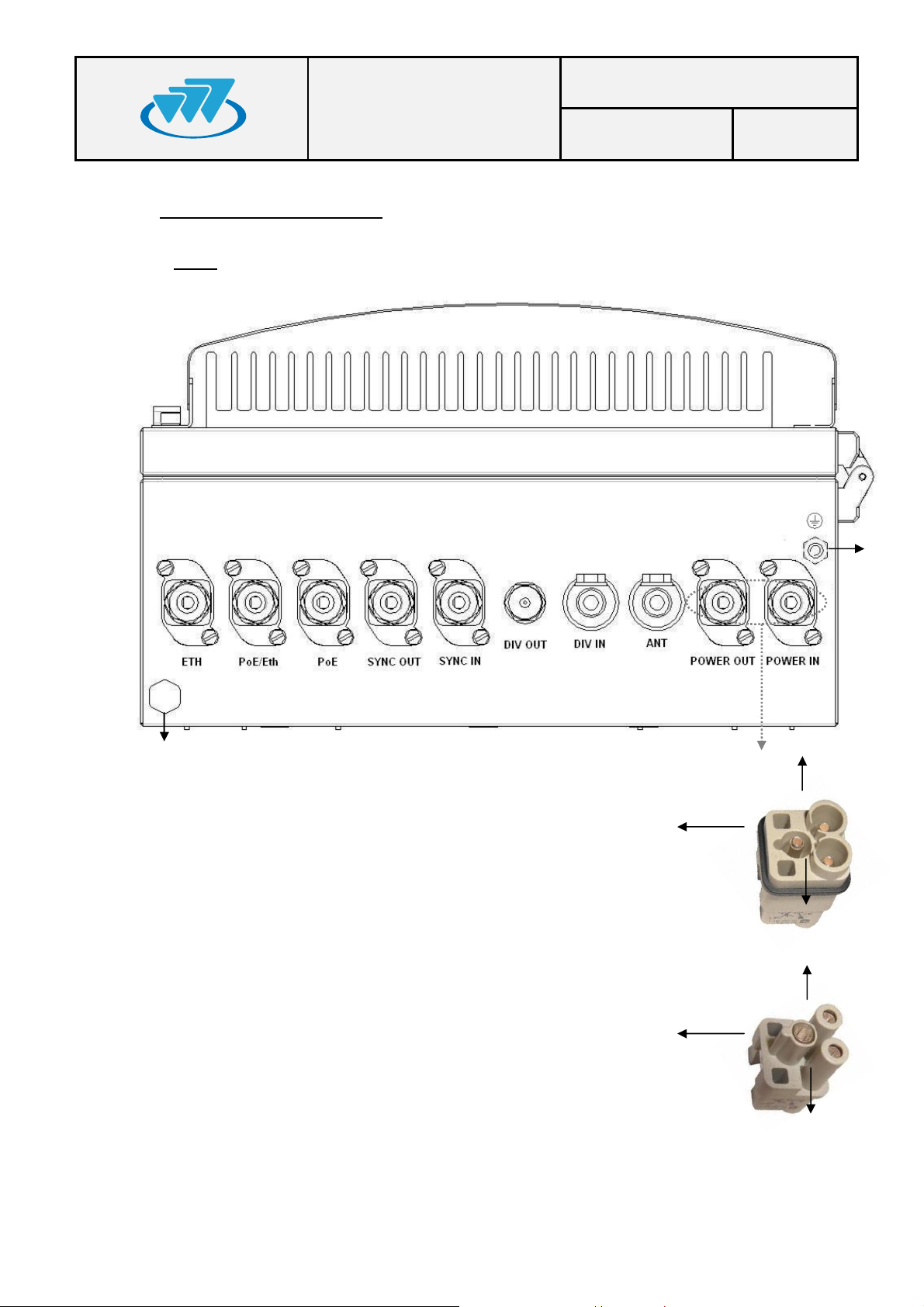
5.2.CONNECTORS
· 1.- Terminal with the following meaning depending on the MBS Unit Power option:
- AC MBS Units: Neutral contact (N).
- DC MBS Units: Negative contact (-).
· 2.- Terminal with the following meaning depending on the MBS Unit Power option:
- AC MBS Units: Line contact (L).
- DC MBS Units: Positive contact (+).
· 3.- Power supply Earth contact.
· 4.- Pressure equalizer.
· 5.- Chassis Earth contact.
Date: 14-Nov-2014 Page: 12 of 41
· ETH: Connector that allows Ethernet connection between MBS Units. It also can be
used as Maintenance Ethernet connector.
· PoE/ETH: Power Over Ethernet (IEEE 802.3at) connector. It provides power supply
(48 VDC) and Ethernet connection to a PoE radio link. It can be used as
Maintenance Ethernet connector if there is not radio link (Poe) connected.
· PoE: Power Over Ethernet (IEEE 802.3at) connector. It provides power supply (48
VDC) and Ethernet connection to a PoE radio link.
· SYNC OUT: Synchronism output connector. It provides synchronism to a second
MBS Unit through its SYNC_IN connector.
· SYNC I N: Synchr onism input connector.
· DIV OUT: Output reception connector. It provides the receiver chain 2 to the next
MBS Unit through its DIV IN connector.
· DIV IN: Reception antenna connector (receiver chain 2). It is connected to an
antenna or to a MBS Unit DIV OUT connector (diversity 2).
· ANT: Transmission/reception antenna power connector (receiver chain 1).
· POWER OUT: Output power supply connector. It provides power supply to another
MBS Unit with the same Power Supply option.
· POWER IN: Input power supply conn ector (VAC or VDC).
01.01.00/1 Rev.1
MBS USER AND
LED
TYPE
NORMAL STATE
FUNC
T
IÓN
·
Code: D148X01PT_DDS06
INSTALLATION
MANUAL
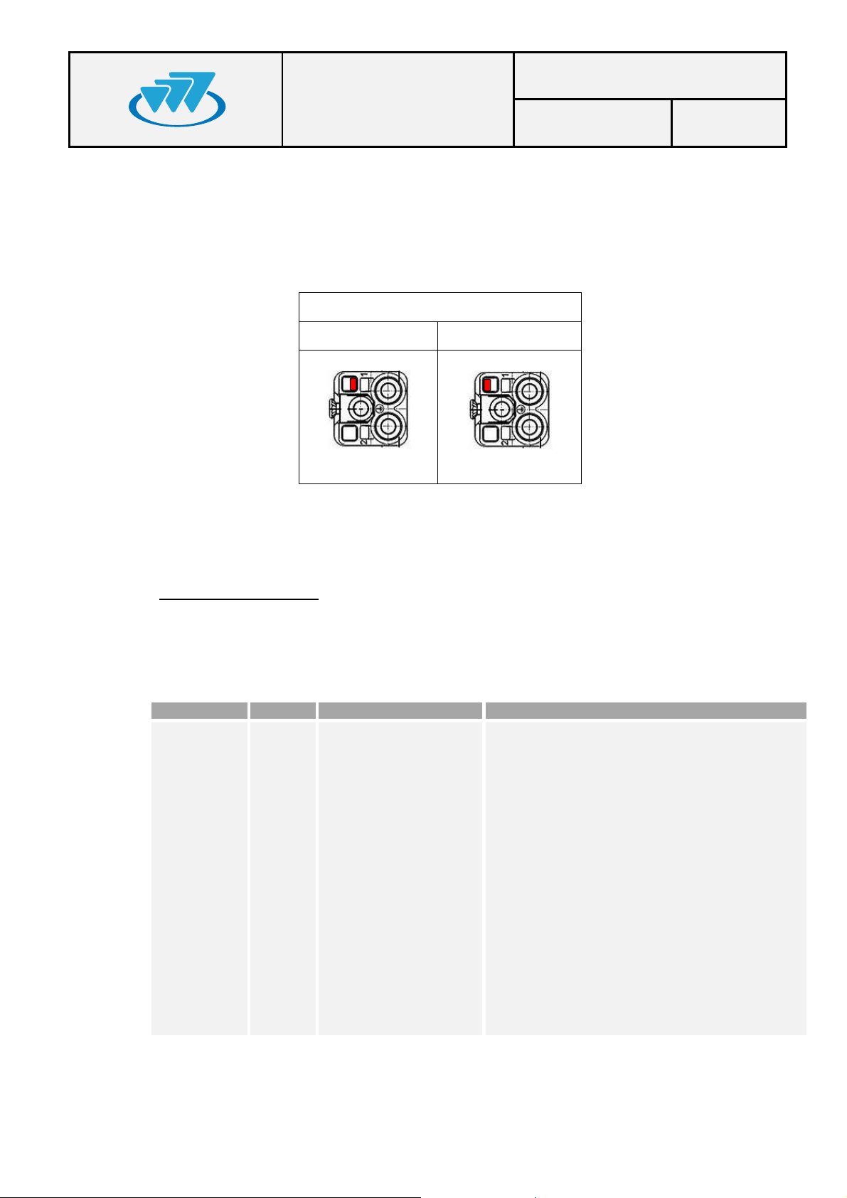
Note: POWER_IN and POWER_OUT connectors have a coding key to avoid wrong
connections; on the following table is showed the location of this coding key depending on
the MBS Unit power supply option.
External view of power supply panel connector
AC Power Supply DC Power Supply
Date: 14-Nov-2014 Page: 13 of 41
Note: The amount of power delivered by both PoE and PoE/ETH connectors to the radio
links can not exceed 35 W in total.
5.3.VISUAL INDICATORS
A MBS Unit has a LED indicator that, depending on its state, will indi cate the function of the MBS Unit
The LEDs show the MBS Unit state:
STATE Tricolor Green ON / Orange ON
Green On: MBS Unit is operating and
transmitting.
· Green flashing: MBS Unit initializing
· Red On: There is no link with CNC and no
control from any LSC.
· Red flashing: When MBS Unit is
controlled by the CNC, showing any kind
of alarm other than the communication one
is NOT OK.
· Orange On: MBS Unit is operating and
transmitting in fallback mode.
· Orange flashing: When MBS Unit is in
fallback mode, showing any kind of alarm
other than the communication one is NOT
OK.
· OFF: The equipment is either without
power source or is damaged.
01.01.00/1 Rev.1
 Loading...