

Page 1
MBS USER AND INSTALLATION MANUAL
CLASSIFICATION:
PRODUCT:
CODE:
VERSION:
MBS
D148X01PT_DDS06
03
REVISION:
00
DATE:
General information Internal document
DOCUMENT MAINTENANCE
THIS DOCUMENT HAS 17 PAGES
EDIT. DATE AUTHOR DESCRIPTION
1.0 05-Oct-2011 Javier Córdova First edition.
2.0 02-May-2012 Javier Córdova
3.0 19-Dec-2012 A. González
Changes in section 4.
Document code and minor editorial changes.
Addition of labelling information and FCC RF
Exposure Requirements.
19-Dec-2012
DOCUMENT APPROVAL
ACTIVITY NAME DATE SIGNATURE
Prepared
Revised
Project Manager
Approved
R&D Director
01.01.00/1 Rev.1
Page 2

MBS USER AND
Code: D148X01PT_DDS06
INSTALLATION
PowerTrunk Inc. is the subsidiary of Teltronic S.A.U. responsible for business development, distribution and
customer support for Teltronic’s Land Mobile Radio products in North America. The company is headquartered in
New York City. Teltronic S.A.U. distributes the same products for Land Mobile Radio under different trademarks
and brand names in other regions of the world.
Disclaimer
Although every reasonable effort has been made to ensure the accuracy of the information contained herein and
any other referred document, this should not be construed as a commitment on the part of Teltronic S.A.U.
and/or PowerTrunk Inc., and the liability of Teltronic S.A.U. and/or PowerTrunk Inc. for any errors and omissions
shall be limited to the correction of such errors and omissions. Teltronic S.A.U. and/or PowerTrunk Inc.
welcomes any comment as a way to improve any delivered documentation.
The information contained herein has been prepared for the use of appropriately trained personnel, and it is
intended for the purpose of the agreement under which the information is submitted. Any party using or relying
upon this information assumes full responsibility for such use and in no event shall Teltronic S.A.U. and/or
PowerTrunk Inc. be liable to anyone for especial, collateral, incidental, or consequential damages in connection
with or arising out of the use of this information.
The information or statements given in these documents regarding the suitability, capacity or performance of the
mentioned hardware or software products cannot be considered binding but shall be defined in the agreement
made between Teltronic S.A.U. and/or PowerTrunk Inc. and the customer.
Teltronic S.A.U. and/or PowerTrunk Inc. reserves the right to revise these documents and to make changes to its
content at any time, without prior notification.
Copyrights
No part of the information contained herein and the other referred documents may be copied, distributed or
transmitted by any means to any other party without prior written permission of Teltronic S.A.U. and/or
PowerTrunk Inc. The distribution of this document may be also covered by NDA (non-disclosure agreement)
between Teltronic S.A.U. and/or PowerTrunk Inc. and the receiver.
Please also note that part of these contents even may be covered by patent rights.
This document, the referred documents and the described product are considered protected by copyright
according to the applicable laws.
PowerTrunk and the PowerTrunk logo are registered trademarks of Teltronic S.A.U.
Copyright © PowerTrunk Inc. All rights reserved
MANUAL
Date: 19-Dec-2012 Page: 2 of 36
01.01.00/1 Rev.1
Page 3

MBS USER AND
Code: D148X01PT_DDS06
INSTALLATION
CONTENTS:
1.
INTRODUCTION.........................................................................................................4
2.
UNPACKING AND CHECKING..................................................................................4
3.
PREVIOUS CONSIDERATIONS.................................................................................4
4.
LABELLING AND INFORMATION ON SAFETY AND ELECTROMAGNETIC
COMPATIBILITY..................................................................................................................5
5.
EQUIPMENT DESCRIPTION......................................................................................7
5.1.
VIEW....................................................................................................................7
5.2.
CONNECTORS....................................................................................................8
6.
INSTALLATION GUIDE............................................................................................10
6.1.
NECESSARY EQUIPMENT ...............................................................................11
MANUAL
Date: 19-Dec-2012 Page: 3 of 36
6.2.
BASIC PRE-CONFIGURATION.........................................................................13
6.3.
INSTALLATION .................................................................................................14
6.3.1. MAST/POLE INSTALLATION..........................................................................15
6.3.2. WALL INSTALLATION....................................................................................20
6.3.3. ANTI-VANDAL KIT INSTALLATION................................................................23
6.3.4. CONNECTIONS..............................................................................................25
7.
START UP/CONFIGURATION/VERIFICATION .......................................................35
8.
INCIDENTS...............................................................................................................36
8.1.
INTERFERENCE AT MBS UNIT........................................................................36
8.2.
OVER VOLTAGE PROTECTION.......................................................................36
01.01.00/1 Rev.1
Page 4
MBS USER AND
Code: D148X01PT_DDS06
INSTALLATION
MANUAL
Date: 19-Dec-2012 Page: 4 of 36
1. INTRODUCTION
The MBS Units are the outdoor modules that make up a Mast Mounted Base Station (MBS).
They are independent units that can be interconnected with each other to increase the base
station capacity. A MBS consists of a maximum of two MBS Units.
This manual is common to all the equipment models, including all their options and
accessories.
The proper operation of any electronic device depends on its correct use. Therefore, it is
recommended to follow the instructions showed in this manual.
2. UNPACKING AND CHECKING
The equipment is supplied with all the necessary materials for the installation, either on a
mast/pole or on a wall:
MBS Unit includes the followings items
One power connector.
One Ethernet connector
RF super-flexible wire N-Male – N-Male.
Brackets for the installation.
Besides, in some types of installation, as detailed below, it is necessary an additional
material that is NOT supplied with the equipment.
IMPORTANT: If any of the necessary elements to carry out the installation process
described in this guide is missing or damaged, please contact your supplier.
3. PREVIOUS CONSIDERATIONS
This manual contains information about instructions for installation, maintenance and use.
Read the following pages before using this equipment.
It is not advisable to switch on the equipment without having previously connected the
antenna otherwise irreparable damage could be. It is important to use an antenna adjusted
to the work frequency.
01.01.00/1 Rev.1
Page 5
MBS USER AND
Code: D148X01PT_DDS06
INSTALLATION
4. LABELLING AND INFORMATION ON SAFETY AND ELECTROMAGNETIC
COMPATIBILITY
The equipment is supplied with an identification label where the model, the IC
Certificate number and the FCC ID are displayed depending on the frequency work band.
The equipment has been designed to fulfil the applicable compliance regulations.
The equipment complies with the applicable Parts of the FCC Title 47 of the Code of
Federal Regulations and Industry Canada (IC) RSS-119 Standard.
This device complies with part 15 of the FCC Rules and Industry Canada ICES-003.
Operation is subject to the following two conditions: (1) this device may not cause
interference, and (2) this device must accept any interference, including interference that
may cause undesired operation of the device.
Changes or modifications not expressly approved by the party responsible for
compliance could void the user's authority to operate the equipment.
FCC RF Exposure Requirements:
CAUTION:
The antenna(s) used for this transmitter must not be co-located or operating in
conjunction with any other antenna or transmitter.
Antennas used for this transmitter must not exceed an antenna gain of 20 dBi and
be located at least 400 cm, away from any person(s) in order to comply with the FCC RF
exposure requirements.
Failure to observe these restrictions will result in exceeding the FCC RF exposure
limits.
MANUAL
Date: 19-Dec-2012 Page: 5 of 36
01.01.00/1 Rev.1
Page 6

MBS USER AND
Code: D148X01PT_DDS06
INSTALLATION
The following labels will be placed in conspicuous view on the MBS Unit:
MANUAL
Date: 19-Dec-2012 Page: 6 of 36
Most electronic equipment is susceptible to electromagnetic
interference if it is not duly protected. If the MBS Unit is placed near
unprotected electronic devices, they may malfunction.
The MBS Unit must not transmit without its antenna connected.
When installing the antenna, follow the guidelines for exposure of the
human body to high and low frequency electromagnetic fields. Follow
the supplier’s / manufacturer’s instructions.
Burns may be suffered if the antenna connector output is touched by
bare skin when the MBS Unit is transmitting with the antenna
disconnected.
Take care when handling the MBS Unit. It has edges, which may cut if
handled incorrectly.
Maintenance and repair of these repeaters must be carried out by
qualified personnel only.
01.01.00/1 Rev.1
Page 7

MBS USER AND
Code: D148X01PT_DDS06
INSTALLATION
MANUAL
Date: 19-Dec-2012 Page: 7 of 36
5. EQUIPMENT DESCRIPTION
5.1.
VIEW
5
4
1
3
Male panel connector
2
2
3
Female cable connector
1
01.01.00/1 Rev.1
Page 8

MBS USER AND
Code: D148X01PT_DDS06
INSTALLATION
5.2.
CONNECTORS
• 1.- Terminal with the following meaning depending on the MBS Unit Power option:
- AC MBS Units: Neutral contact (N).
- DC MBS Units: Negative contact (-).
• 2.- Terminal with the following meaning depending on the MBS Unit Power option:
- AC MBS Units: Line contact (L).
- DC MBS Units: Positive contact (+).
• 3.- Power supply Earth contact.
• 4.- Pressure equalizer.
• 5.- Chassis Earth contact.
MANUAL
Date: 19-Dec-2012 Page: 8 of 36
• ETH: Connector that allows Ethernet connection between MBS Units. It also can be
used as Maintenance Ethernet connector.
• PoE/ETH: Power Over Ethernet (IEEE 802.3at) connector. It provides power supply
(48 VDC) and Ethernet connection to a PoE radio link. It can be used as
Maintenance Ethernet connector if there is not radio link (Poe) connected.
• PoE: Power Over Ethernet (IEEE 802.3at) connector. It provides power supply (48
VDC) and Ethernet connection to a PoE radio link.
• SYNC OUT: Synchronism output connector. It provides synchronism to a second
MBS Unit through its SYNC_IN connector.
• SYNC IN: Synchronism input connector.
• DIV OUT: Output reception connector. It provides the receiver chain 2 to the next
MBS Unit through its DIV IN connector.
• DIV IN: Reception antenna connector (receiver chain 2). It is connected to an
antenna or to a MBS Unit DIV OUT connector (diversity 2).
• ANT: Transmission/reception antenna power connector (receiver chain 1).
• POWER OUT: Output power supply connector. It provides power supply to another
MBS Unit with the same Power Supply option.
• POWER IN: Input power supply connector (VAC or VDC).
01.01.00/1 Rev.1
Page 9

MBS USER AND
Code: D148X01PT_DDS06
INSTALLATION
Note: POWER_IN and POWER_OUT connectors have a coding key to avoid wrong
connections; on the following table is showed the location of this coding key depending on
the MBS Unit power supply option.
MANUAL
External view of power supply panel connector
AC Power Supply DC Power Supply
Date: 19-Dec-2012 Page: 9 of 36
Note: The amount of power delivered by both PoE and PoE/ETH connectors to the radio
links can not exceed 35 W in total.
01.01.00/1 Rev.1
Page 10
MBS USER AND
Code: D148X01PT_DDS06
INSTALLATION
6. INSTALLATION GUIDE
The following recommendations must be followed before powering on the MBS Unit module.
Next diagram shows the steps to be followed to carry out the installation:
MANUAL
Date: 19-Dec-2012 Page: 10 of 36
Verification of the necessary
Basic Pre-Configuration
Final location installation
Final Configuration/Verification
equipment
01.01.00/1 Rev.1
Page 11
MBS USER AND
INSTALLATION
6.1.
NECESSARY EQUIPMENT
Make sure you have the necessary equipment depending on the
configuration to install. If any of the elements necessary to carry out the
installation process described in this manual, were lost or damaged, contact
Necessary equipment
Element Code Comments
your supplier and / or installer.
MANUAL
Code: D148X01PT_DDS06
Date: 19-Dec-2012 Page: 11 of 36
MBS Unit D148x01
Anti-vandal kit D014000
Ethernet cable connector 225120
RF superflexible wire N-Male
↔ N-Male
208931
“x” varies depending on band.
Each MBS Unit includes:
- MBS Unit equipment
- Power supply cable connector
- Ethernet cable connector
- RF superflexible wire N-Male ↔ N-Male
- Brackets for installation
It is only necessary if anti-vandal protection is
required
Every MBS Unit includes one connector of this
type; if a MBS Unit must be connected to two
radio links, it is necessary to have a second
unit.
Each MBS Unit includes one cable of this type;
if a MBS Unit requires diversity 2 on reception it
is necessary to have a second unit.
Additional carrier
interconnection kit
01.01.00/1 Rev.1
D014001
It is mandatory in case of connecting a second
MBS Unit to the first MBS Unit.
Page 12
MBS USER AND
INSTALLATION
Additional equipment to be considered for installation
Element Comments
MANUAL
Code: D148X01PT_DDS06
Date: 19-Dec-2012 Page: 12 of 36
Cable to power the MBS
Unit.
Ethernet cable to connect
PoE radio links
Antenna coaxial cable and
antenna.
Tools
Element Comments
Toolbox
See features in external power connection section. One power
supply cable connector is supplied with the MBS Unit.
See features in Ethernet connection section. One Ethernet
cable connector is supplied with the MBS Unit.
See features in Antenna connection section.
In addition to the usual material used for installations
(wrenches, screwdrivers ...) it is necessary to use:
- Torque wrench for 17 mm hexagonal nut capable of delivering
15 Nm.
- Vulcanizable tape.
Ethernet Cable
Cable to make specific maintenance tasks in the field
01.01.00/1 Rev.1
Page 13

MBS USER AND
Code: D148X01PT_DDS06
INSTALLATION
6.2.
BASIC PRE-CONFIGURATION
Before connecting the MBS Unit to the infrastructure it should have the IP address
correctly configured in order to have remote access once it is connected (to set the IP
address, see the configuration chapter (F067220) in technical manual).
Steps:
• Apply power supply to the MBS through its POWER_IN connector.
• Wait 3 minutes until the MBS Unit initializes.
• Connect the PC, to set the IP address, to the ETH connector.
• Change the IP address according to the network IP addressing.
• Check that IP address was successfully changed through a “ping” from the PC to the
MANUAL
Date: 19-Dec-2012 Page: 13 of 36
new IP address of the MBS Unit.
01.01.00/1 Rev.1
Page 14
MBS USER AND
Code: D148X01PT_DDS06
INSTALLATION
6.3.
INSTALLATION
The MBS has been designed to be mounted on both mast/pole and wall. This chapter
provides the necessary steps to be followed for a right MBS Unit installation.
At least two people are required to carry out the installation of a MBS Unit on a mast/pole.
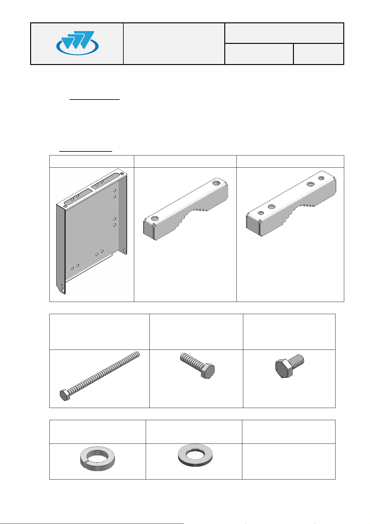
Bracket system:
1 x Bracket 2 x clamp (2 holes) 2 x clamp (4 holes)
MANUAL
Date: 19-Dec-2012 Page: 14 of 36
4 x Bolt M10x180
(Clamp attachment)
12 x Grower washer DIN 127
Ø10
6 x Bolt M10x40
(lateral attachment MBS-
Bracket & Clamp-Bracket)
12 Plain washer DIN125 x
Ø10
2 x Bolt M10x20
(Top attachment MBS-
Bracket)
---
01.01.00/1 Rev.1
Page 15
MBS USER AND
Code: D148X01PT_DDS06
INSTALLATION
MANUAL
Date: 19-Dec-2012 Page: 15 of 36
6.3.1.
MAST/POLE INSTALLATION
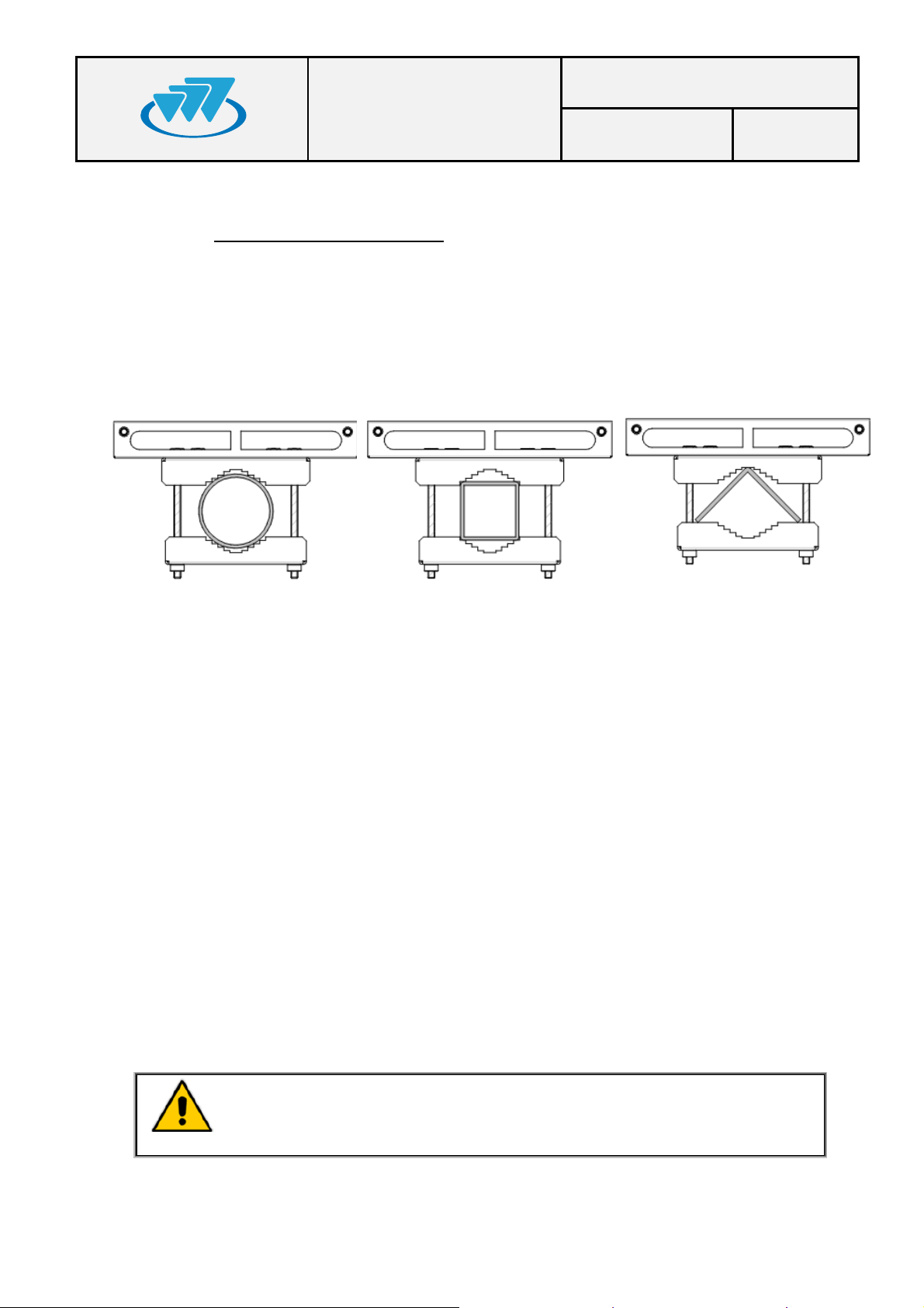
The different section types of mast/pole where the MBS Unit can be mounted are the
following ones:
Circular section: Diameter from 30 mm to 130 mm.
Square section: From 30 mm x30 mm to 85 mm x85 mm.
L section: From 30 mm x30 mm to 110 mm x110 mm.
In the choice of the mast/pole where the MBS Unit is being installed the following
recommendations must be followed:
The mast/pole has to support the loads due to the installation of some elements
on them.
The mast/pole has to support the loads due to the action of the wind, snow as
well as its own weight, because these are going to induce its flexion.
The mast/pole must have the enough inertia both lateral and frontal in order that
the action of different loads does not induce permanent deformations on it.
The manufacturer of the mast/pole must evaluate the structural factor of the
mast/pole correctly depending on its type.
It is necessary to take into account both the height where the MBS Unit is
installed and its weight/dimensions (See section “MBS Unit” in chapter
(F067326) “SBS Technical Description” in the Technical Manual).
It is recommended to choose a lattice mast/pole in case of this one has a
high height and it is going to be submitted to important flexion efforts. In any
case, it is responsibility of the manufacturer of the mast/pole to determine if
the resistant section of mast/pole is suitable.
01.01.00/1 Rev.1
Page 16
MBS USER AND
Code: D148X01PT_DDS06
INSTALLATION
The brackets should be installed tight enough to support the MBS Unit without causing
deformation of the mast/pole or areas of corrosion.
Once mounted in its definitive location, if the vandal resistant kit is available, it will
prevent the access / disassembly not authorized.
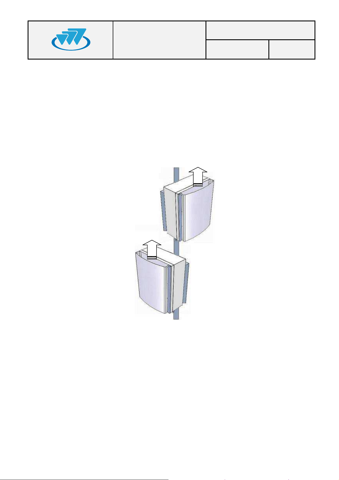
In case of installing more than one MBS Unit on the same mast/pole, it is recommended
not to mount one above the other one to avoid the heat transfer from the MBS Unit low
to the MBS Unit high. If the MBS Units have to be installed in the same vertical axis
these must be oriented in different directions to increase the separation of them as far as
possible, depending on the length of wiring between both equipments (1.5 m
approximately).
MANUAL
Date: 19-Dec-2012 Page: 16 of 36
01.01.00/1 Rev.1
Page 17
MBS USER AND
Code: D148X01PT_DDS06
INSTALLATION
MANUAL
Date: 19-Dec-2012 Page: 17 of 36
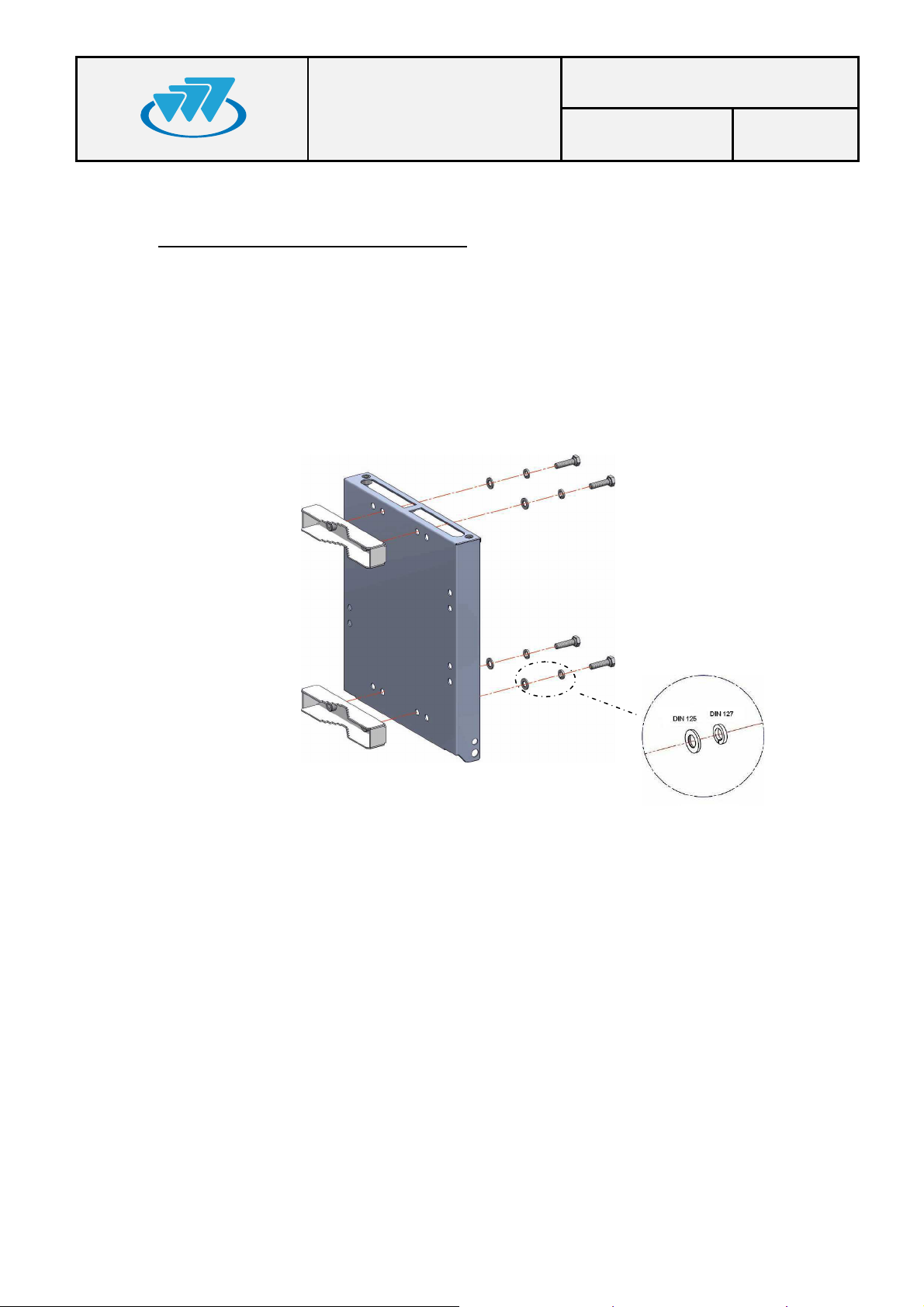
Steps to install a MBS on a mast/pole:
1) Place the MBS Unit bracket on the mast/pole as follows.
Note: Handle the MBS Unit bracket with care if it rests on the floor. Place some
protection underneath to prevent scratches on the surface.
a) Secure 4 holes clamps on the bracket by tightening the bolts with a 15 Nm
torque, using a 17 mm torque wrench, do not forget to place the washers
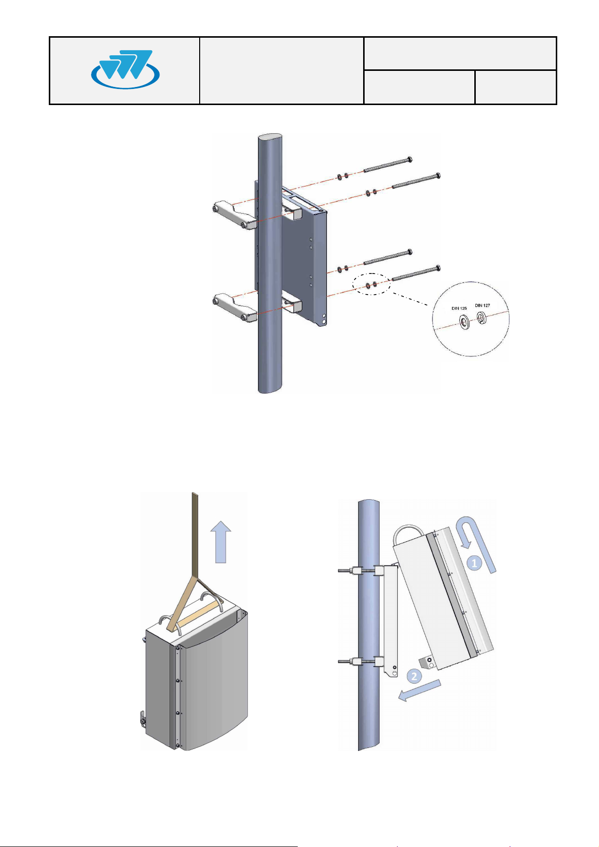
b) Install the bracket to the desired final location on the mast/pole. Embrace the 2
01.01.00/1 Rev.1
holes clamps and screw these to the bracket with a 17 mm wrench and 15 Nm
torque. Due to the length of the bolts it is advisable to screw them slowly.
Page 18
MBS USER AND
Code: D148X01PT_DDS06
INSTALLATION
MANUAL
Date: 19-Dec-2012 Page: 18 of 36
2) Place MBS Unit on the bracket as follows.
a) Raise the MBS Unit to the position where the bracket is placed on the mast/pole
and hang it on the bracket, tilting slightly to match the bracket guides as
indicated in the following figure:
01.01.00/1 Rev.1
Page 19
MBS USER AND
Code: D148X01PT_DDS06
INSTALLATION
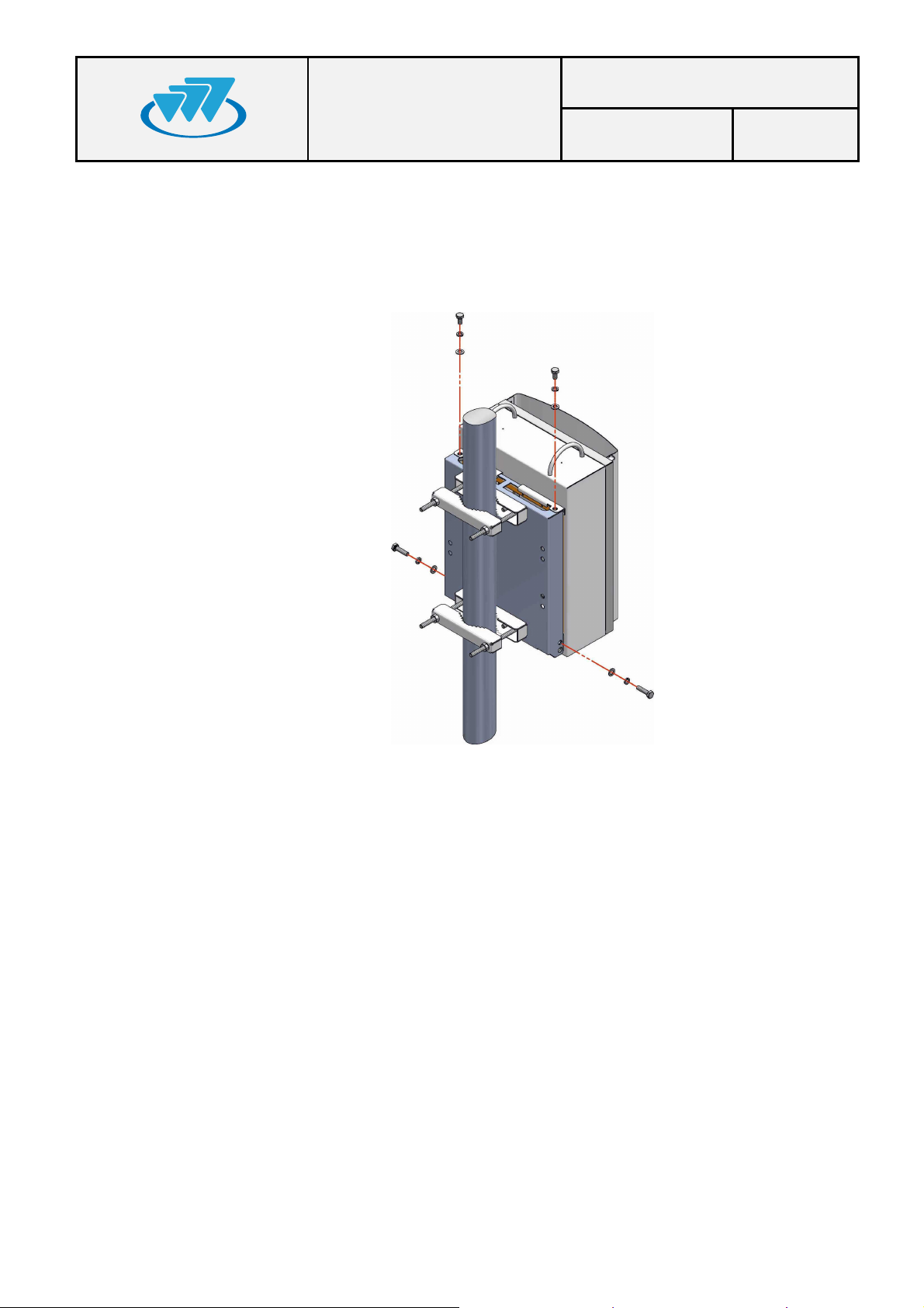
b) Put the bolts of the MBS Unit and washers to the bracket with a 17 mm wrench
and 15 Nm torque.
Note: If anti-vandal kit is available (D014000), lateral bolts should be placed after
mounting the anti-vandal kit.
MANUAL
Date: 19-Dec-2012 Page: 19 of 36
3) Make the necessary cable connections as described in the connections section in
this guide.
01.01.00/1 Rev.1
Page 20
MBS USER AND
Code: D148X01PT_DDS06
INSTALLATION
MANUAL
Date: 19-Dec-2012 Page: 20 of 36
6.3.2.
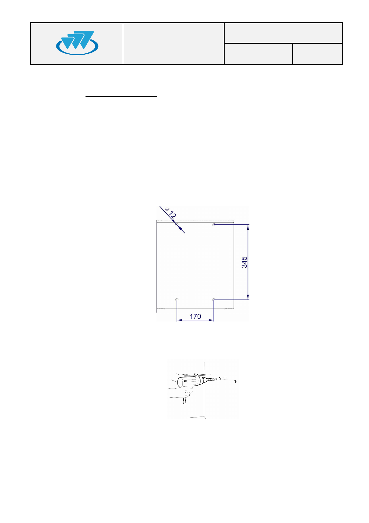
To install the MBS Unit on a wall, make the following steps:
1) Mark the position of the holes using the bracket as a template itself with the help of a
WALL INSTALLATION
level.
Note: To ensure proper ventilation there must be at least 700 mm clearance above
and below each MBS Unit. There must also be a minimum distance of 300 mm free
on both sides of the MBS Unit.
Note: The screws, expansion bolts and washers needed to secure the brackets to
wall are not supplied with the unit.
The distance between the holes are shown in the following figure.
2) Drill holes on the wall and insert a rawlplug in each hole.
01.01.00/1 Rev.1
Page 21
MBS USER AND
Code: D148X01PT_DDS06
INSTALLATION
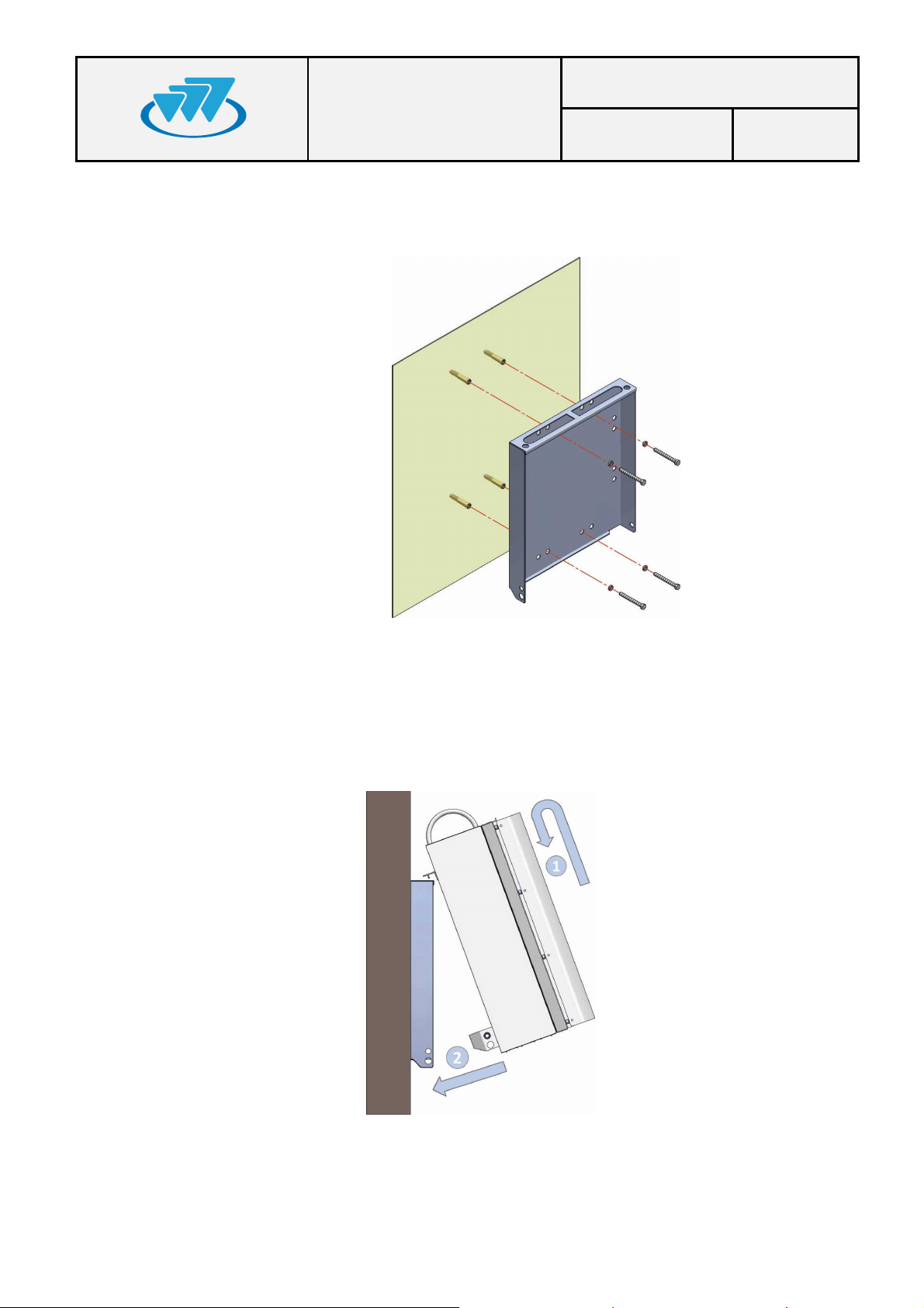
3) Place the bracket over the rawlplug and insert the bolts and washers. Finally screw
them with a 17 mm wrench and 15 Nm torque.
MANUAL
Date: 19-Dec-2012 Page: 21 of 36
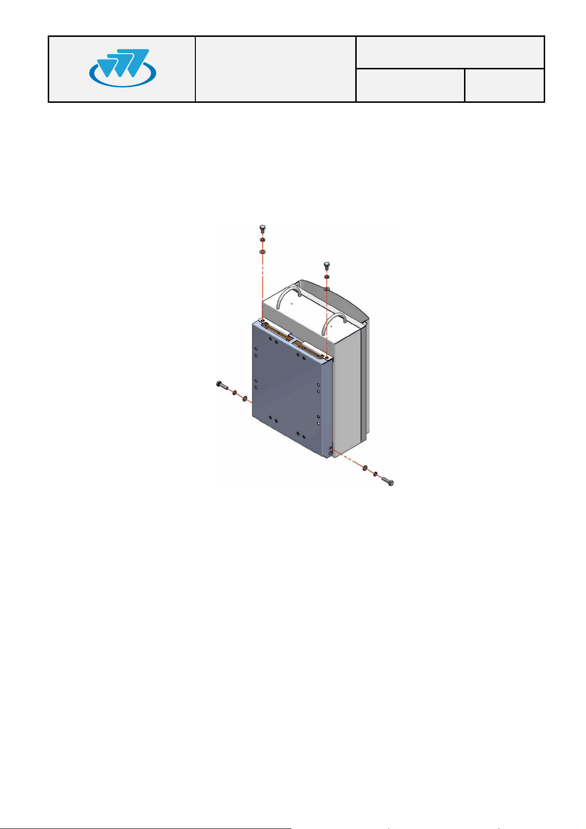
4) Place the MBS Unit on the bracket as follows.
a) Raise the MBS Unit to the position where the bracket is placed and hang it on the
bracket, tilting slightly to match the anchor guides as indicated in the following
figure:
01.01.00/1 Rev.1
Page 22
MBS USER AND
Code: D148X01PT_DDS06
INSTALLATION
b) Put the bolts of the MBS Unit and washers to the bracket with a 17 mm wrench
and 15 Nm torque. The order is bolt + grower washer + plain washer.
Note: If anti-vandal kit is available (D014000), lateral bolts should be placed after
mounting the anti-vandal kit.
MANUAL
Date: 19-Dec-2012 Page: 22 of 36
5) Make the necessary cable connections as described in the connections section in
this guide.
01.01.00/1 Rev.1
Page 23
MBS USER AND
Code: D148X01PT_DDS06
INSTALLATION
MANUAL
Date: 19-Dec-2012 Page: 23 of 36
6.3.3.
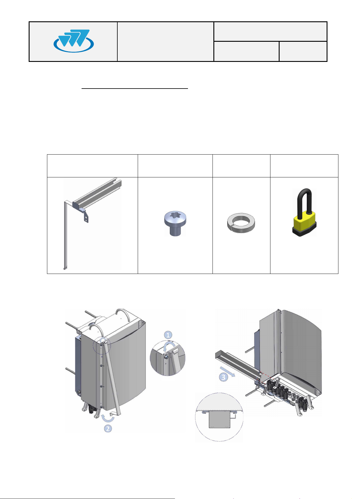
The anti-vandal kit for MBS Unit is an optional accessory (D014000). Either the MBS
Unit is mounted on a mast/pole or on a wall, the anti-vandal kit, is performed as follows.
Take into account that the installation of the ant-vandal kit should be done once you
have completed the wiring connections of the MBS Unit.
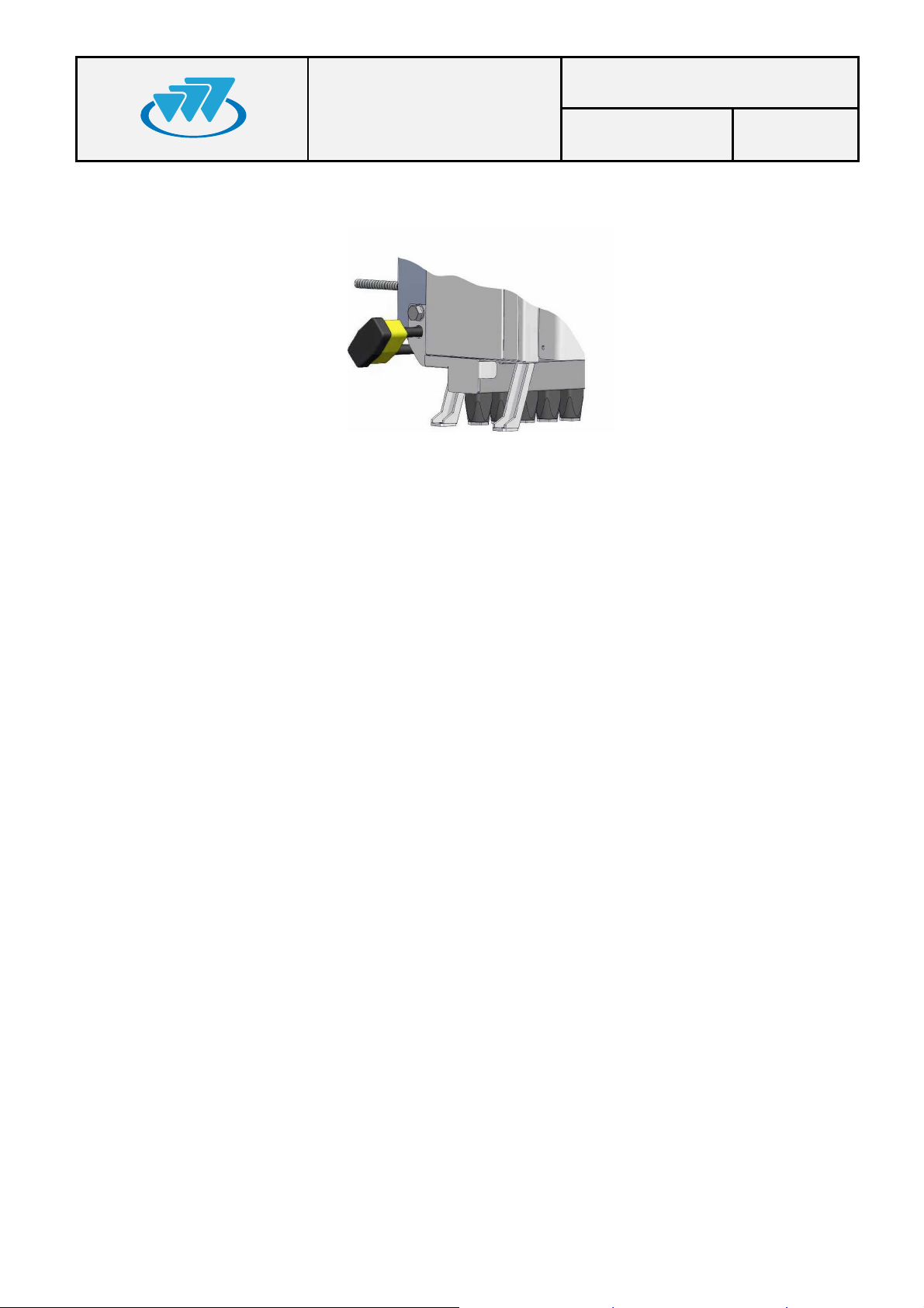
Anti-vandal Kit:
ANTI-VANDAL KIT INSTALLATION
Anti-Vandal Kit 6 x
Torx screw M3X4
6 x Grower
washer
1 x padlock
- Place the anti-vandal kit and slide the kit guides as shown on the following figure:
01.01.00/1 Rev.1
Page 24
MBS USER AND
Code: D148X01PT_DDS06
INSTALLATION
- Place the padlock and screw the attachment bolt to the bracket with a 17 mm
wrench and 15 Nm torque.
MANUAL
Date: 19-Dec-2012 Page: 24 of 36
01.01.00/1 Rev.1
Page 25

MBS USER AND
Code: D148X01PT_DDS06
INSTALLATION
MANUAL
Date: 19-Dec-2012 Page: 25 of 36
6.3.4.
This section shows the connections to be made and the characteristics of the material to
be used. The MBS Unit is a weather-protected device once the equipment has been
installed in its final location; make sure that there is no MBS Unit connector without plug
or cable connected. Besides, the external wiring connections of the MBS Unit must be
protected from weather, (vulcanizable tape can be used if it is necessary).
CONNECTIONS
01.01.00/1 Rev.1
Page 26
MBS USER AND
Code: D148X01PT_DDS06
INSTALLATION
MANUAL
Date: 19-Dec-2012 Page: 26 of 36
6.3.4.1.
SUPPORTED CONFIGURATIONS
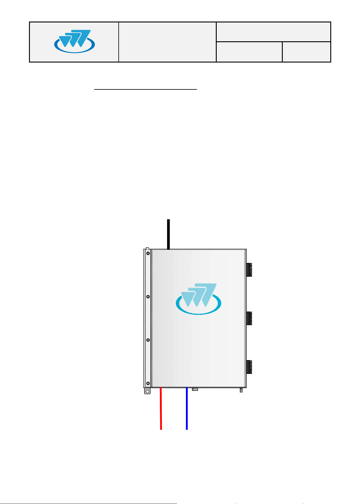
a) ONE MBS UNIT WITHOUT DIVERSITY IN RECEPTION
The connections are the following ones:
Power supply 220/110 VAC or 24 VDC.
From ANT connector to the antenna.
Connection with radio link through PoE connector.
Maintenance through PoE/ETH N or ETH connector.
Antenna 1 (Tx/Rx)
ANT
DIV_IN
Of
POWER_OUT
POWER_IN
PoE/ETH
PoE
Power Input
Radio link
DIV_OUT
ETH
SYNC_OUT
SYNC_IN
01.01.00/1 Rev.1
Page 27
MBS USER AND
INSTALLATION
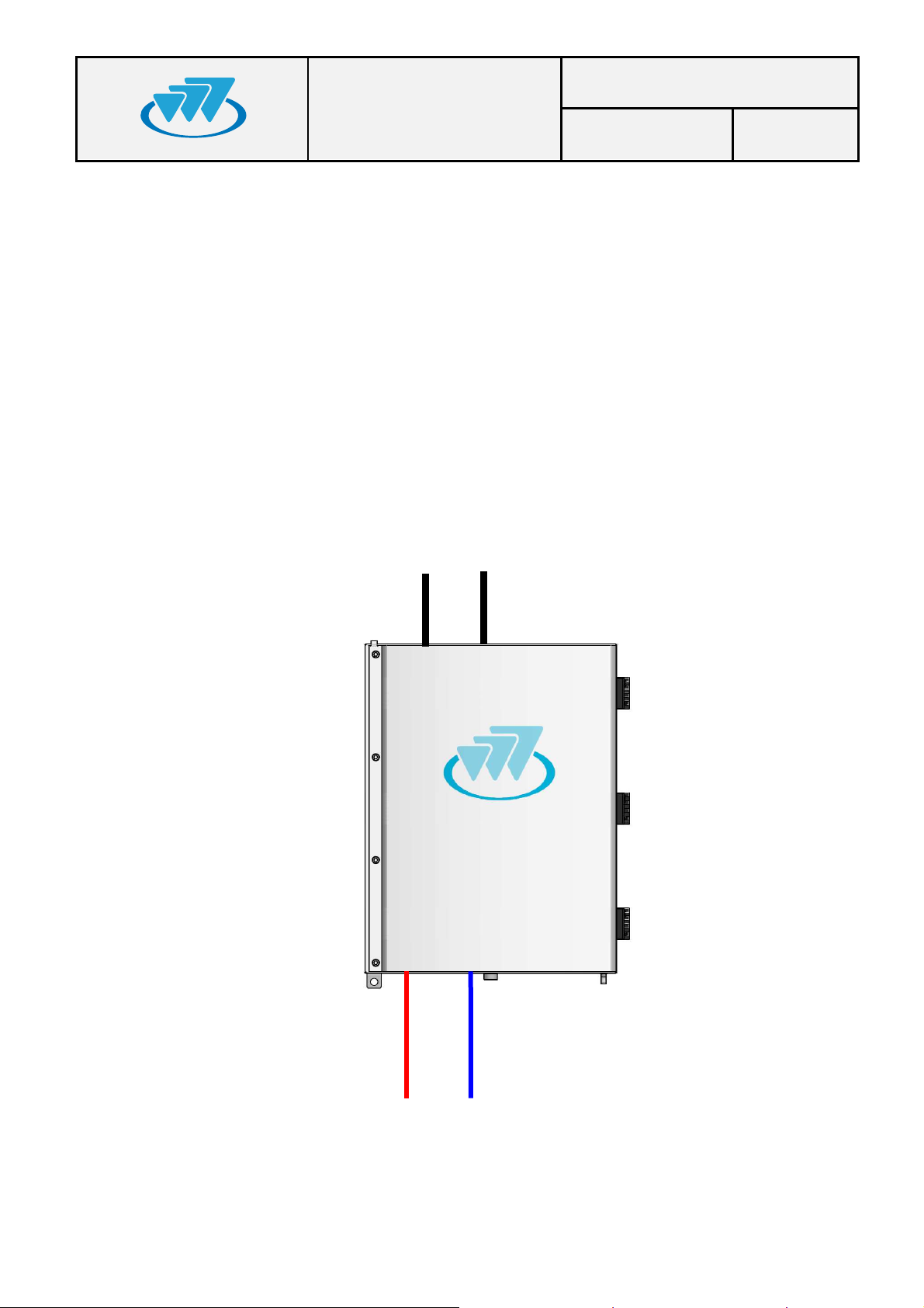
b) ONE MBS UNIT WITH DIVERSITY 2 IN RECEPTION
The connections are the following ones:
Power supply: 220/110 VAC ó 24 VDC.
From ANT connector to the first antenna.
From DIV IN connector to the second antenna.
Connection with the radio link through PoE connector.
Maintenance through PoE/ETH or ETH connector.
MANUAL
Code: D148X01PT_DDS06
Date: 19-Dec-2012 Page: 27 of 36
Antenna 1 (Tx/Rx1)
Antenna 2 (Rx2)
ANT
DIV_IN
DIV_OUT
POWER_OUT
POWER_IN
PoE/ETH
PoE
ETH
SYNC_OUT
SYNC_IN
Power
01.01.00/1 Rev.1
Radio link
Page 28
MBS USER AND
Power
Radio link_2
Radio link_1
ANT
DIV_I
N
DIV_OUT
POWER_IN PoE/ETH SYNC_OUT POWER_OUT PoE ETH SYNC_IN
Anten
n
a 2 (TX
F2
/Rx2)
Ante
n
na 1 (Tx
F1
/Rx1)
ANT
DIV_IN
DIV_OUT
POWER_IN PoE/ETH SYNC_OUT POWER_OUT PoE ETH SYNC_IN
INSTALLATION
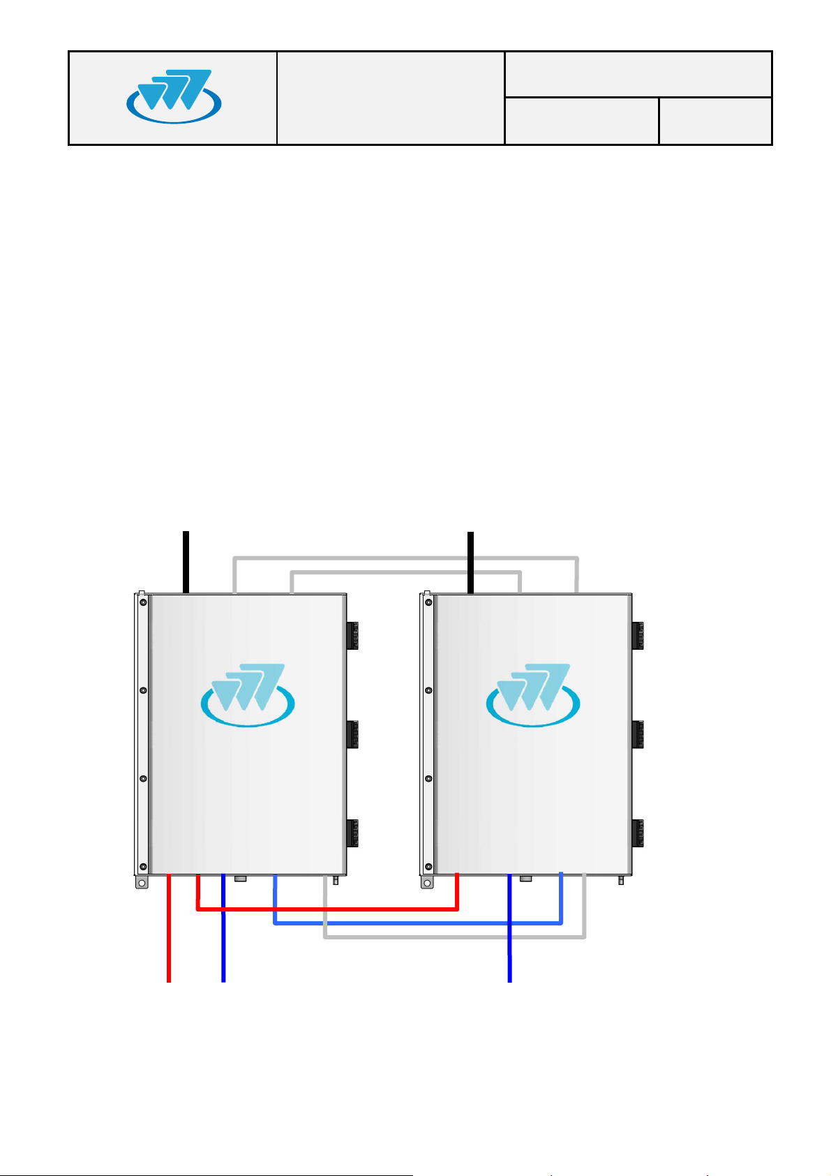
c) TWO MBS UNIT WITH DIVERSITY 2 IN RECEPTION
The connections are the following ones:
Power supply for the MBS Unit 1: 220/110 VAC or 24 VDC.
From ANT connector of the MBS Unit 1 to the first antenna.
From ANT connector of the MBS Unit 2 to the second antenna.
Connection with the radio links through PoE connector of both MBS Units.
Maintenance through PoE/ETH connector of both MBS Units
MANUAL
Code: D148X01PT_DDS06
Date: 19-Dec-2012 Page: 28 of 36
TX
: Output Transmission Frequency 1
F1
TX
: Output Transmission Frequency 2
F2
RX1: Reception “Chain 1” of frequencies 1 y 2
RX2: “Recepetion Chain 2” of frequencies 1 y 2
01.01.00/1 Rev.1
Page 29
MBS USER AND
Code: D148X01PT_DDS06
INSTALLATION
MANUAL
Date: 19-Dec-2012 Page: 29 of 36
6.3.4.2.
CONNECTION OF THE EXTERNAL POWER SUPPLY
Check that the power supply source and/or the battery to be used are
adapted to the type of MBS Unit (AC/DC) and meets the voltage and current
requirements necessary to supply the equipment.
a) MBS Unit with AC power supply source:
Nominal voltage: 110/220 VAC (Range: from 94 to 264 VAC).
Use the power cable connector provided with the MBS Unit to connect the
MBS Unit to the power supply source. Use a cable of 3 wires; with weather
protection; with the following features:
Cable diameter: 6 mm - 12 mm.
Cable section: 4 mm² (0.6/1KV) or AWG-11.
Ensure that the connection is made in the correct way (Line, Neutral and
Earth) following the next steps:
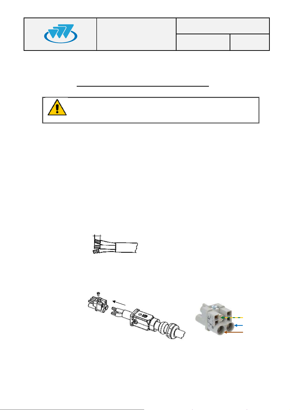
Strip cable and wires (stripping length 8 mm -9 mm).
8-9mm
NOTE: The earth cable must be 2 mm longer.
Push the cable through the cable gland and the hood/housing and
insert the wires into the insert respecting the correct polarity.
Earth (PE)
Neutral (N)
Line (L)
01.01.00/1 Rev.1
Page 30
MBS USER AND
Code: D148X01PT_DDS06
INSTALLATION
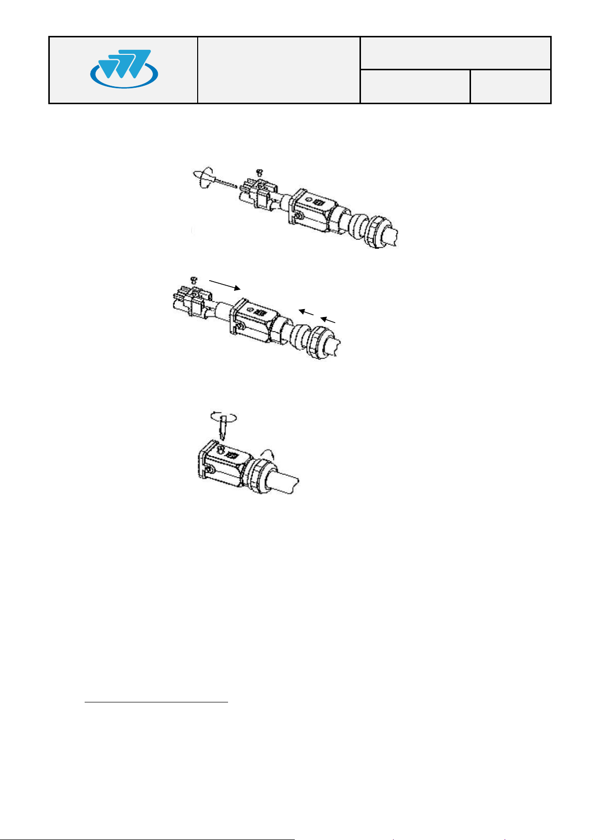
Fix each wire tightening each pin from the front side with a hexagonal
screwdriver (Allen number 2).
Push the insert back into the hood/housing.
MANUAL
Date: 19-Dec-2012 Page: 30 of 36
Fix the assembly tightening the top locking screw and tightening the
cable gland nut on the back of the hood/housing.
b) MBS Unit with DC power supply source:
Nominal voltage: 24 VDC (Range: from 21.6 to 31.2 VDC).
Use the power cable connector provided with the MBS Unit to connect the
MBS Unit to the power supply source. Use a cable of 3 wires with weather
protection and the following features:
Cable diameter: 10 mm - 14 mm.
Cable section: 6 mm² (0.6/1KV) or AWG-10.
Maximum cable length1:
- One MBS Unit: 85 m.
- Two MBS Units: 42 m.
1
The greater the cable length, the greater the voltage drop in it. The specified length has been calculated to ensure
minimum operating voltage of the MBS Unit, assuming a minimum voltage of 24V at the output of the power system and a
typical resistivity of copper wire Ω ≤ 0.0172 mm
01.01.00/1 Rev.1
2
/m.
Page 31
MBS USER AND
Code: D148X01PT_DDS06
INSTALLATION
Ensure that the connection is made in the correct way (Positive, Negative
and Earth) following the next steps:
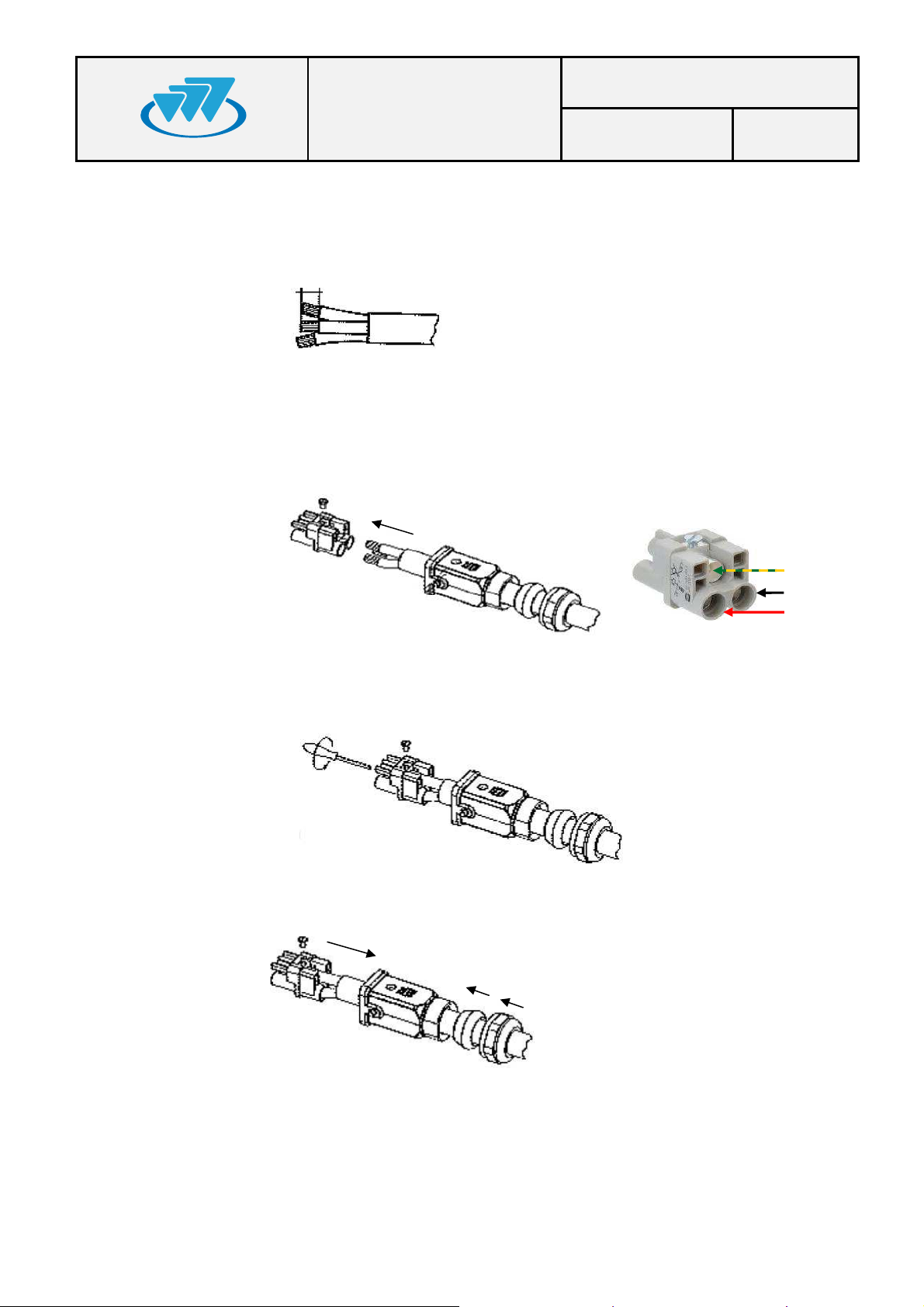
Strip cable and wires (stripping length 8 mm - 9 mm).
8-9mm
NOTE: The Earth cable must be 2 mm longer.
Push the cable through the cable gland and the hood/housing and
insert the wires into the insert respecting the correct polarity.
MANUAL
Date: 19-Dec-2012 Page: 31 of 36
Earth (PE)
Negative (-)
Positive
(+)
Fix each wire tightening each pin from the front side with a hexagonal
screwdriver (Allen number 2).
Push the insert back into the hood/housing.
01.01.00/1 Rev.1
Page 32
c) In both cases:
MBS USER AND
Code: D148X01PT_DDS06
INSTALLATION
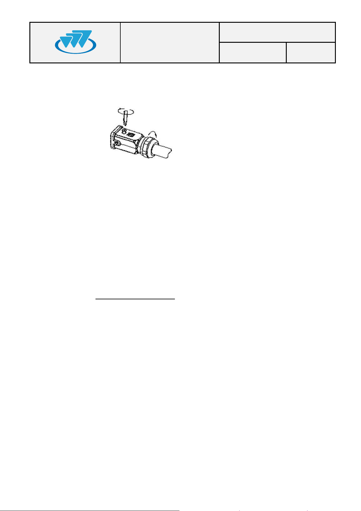
Fix the assembly tightening the top locking screw and tightening the
cable gland nut on the back of the hood/housing.
The power supply cable to the MBS Unit must be provided by the installer
with the proper power supply connector adapted for the connection to the
electrical network or to a 24 VDC source
MANUAL
Date: 19-Dec-2012 Page: 32 of 36
6.3.4.3.
Ensure that the earth connection is made. The MBS Unit has an earth
connector; this connector will connect to the earth protection of the
installation, which is different to the earth protection of the lightning rod.
Make this connection with a cable of, at least, 25 mm2 section (or AWG-3).
NEVER use a gas or electricity conduit as an earth.
ANTENNA CONNECTION
With every MBS Unit, a RF super-flexible wire, N-Male – N-Male, is supplied
to connect the ANT connector of the MBS Unit with the RF wire of the
antenna.
Note: In case of installation a MBS Unit with diversity 2, it is recommended to
contact your supplier and/or installer who will provide the additional RF
super-flexible wire (Cod. 208931).
The RF assembly depends on the cable type used in the installation up to the
antenna.
The RF cable must have a protection against water entry (vulcanizable tape).
Choose the most adaptable antenna for the installation. The antenna must
have an impedance of 50 ohms to the equipment transmission frequency.
Install the antenna in accordance with the manufacturer’s instructions.
Use a coaxial cable, avoiding as much as possible large cable lengths. Cable
impedance is 50 ohms.
01.01.00/1 Rev.1
Page 33
MBS USER AND
Code: D148X01PT_DDS06
INSTALLATION
In installations with diversity, the greatest gain is achieved by placing the
antennas on the same horizontal plane with a minimum distance of 5.5 m
between them.
Measure the ROE of the installation. Never accept a ROE greater than 2.
MANUAL
Date: 19-Dec-2012 Page: 33 of 36
6.3.4.4.
EXTERNAL ETHERNET CONNECTION
The Ethernet cable connector, to connect the MBS Unit with the radio link
(PoE), is supplied with every MBS Unit.
Note: In the case of connection to two radio links, it is recommended to
contact your supplier and/or installer who will provide the additional Ethernet
cable connector.
The Ethernet wire for the radio link connections is supplied by the installer,
and must have the following characteristics:
Cable with 8 wires, FTP cat5E with outdoor protection.
Diameter: 6.5 mm to 9.5 mm.
Maximum length: 100 m
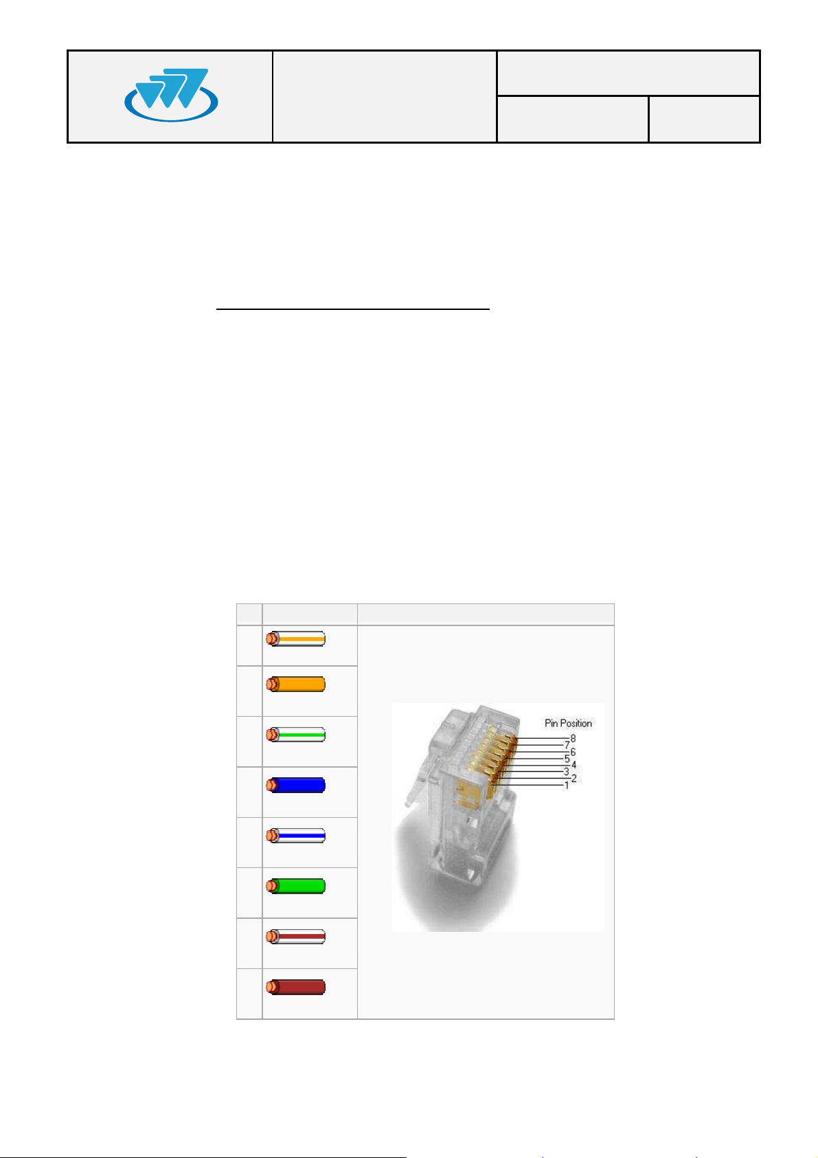
Mount the wire on the connector according to the TIA / EIA 568B
standard (The assembly requires no tools, is done manually).
Pin Color T568B Pins on plug face (socket is reversed)
1
White/Orange
2
Orange
01.01.00/1 Rev.1
3
White/Green
4
Blue
5
White/Blue
6
Green
7
White/Brown)
8
Brown
Page 34
MBS USER AND
ANT
DIV_IN
DIV_OUT
POWER_IN PoE/ETH SYNC_OUT POWER_OUT PoE ETH SYNC_IN
ANT
DIV_IN
DIV_OUT
POWER_IN PoE/ETH SYNC_OUT POWER_OUT PoE ETH SYNC_IN
Code: D148X01PT_DDS06
INSTALLATION
MANUAL
Date: 19-Dec-2012 Page: 34 of 36
6.3.4.5.
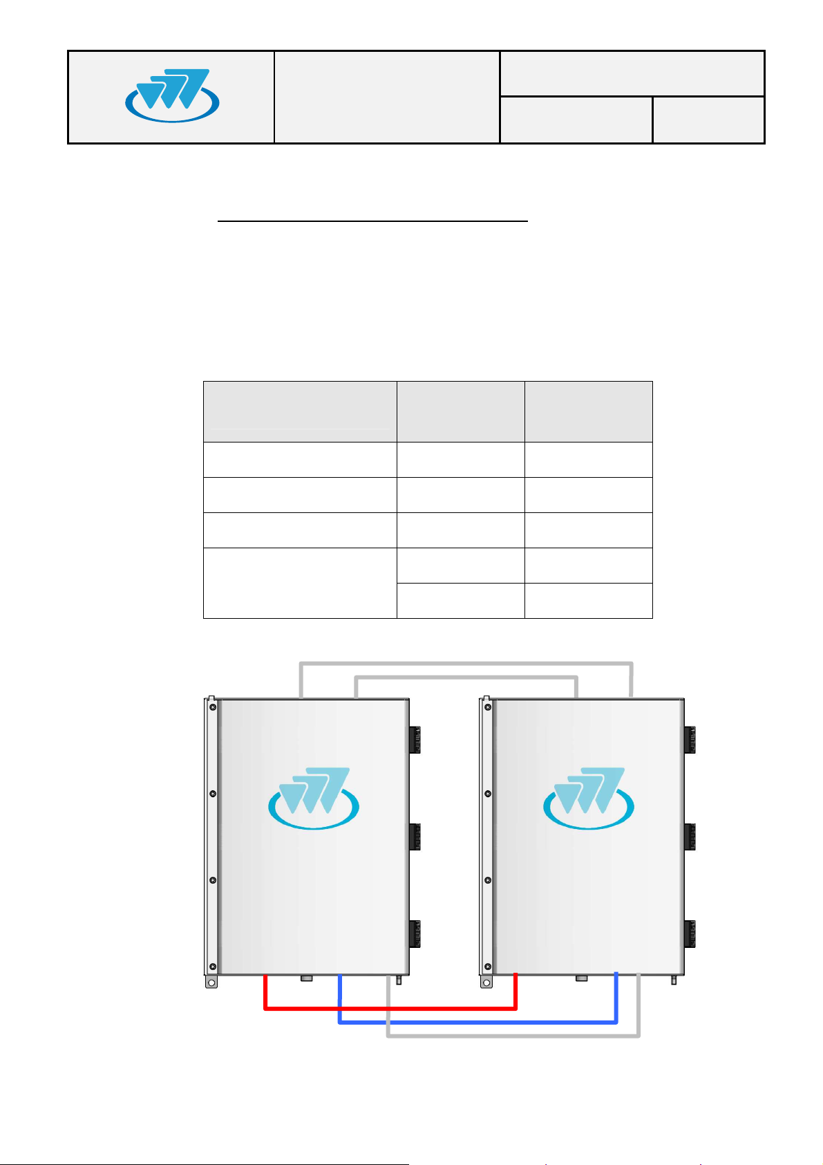
CONNECTION BETWEEN TWO MBS UNITS
To connect two MBS Units you must have the interconnection kit for additional carrier
(Cod. D014001). This is obtained as an independent accessory.
Apart from the power wiring, antennas and radio links to connect as indicated in the
section of supported configurations, it should be considered the use of interconnection
kit between the two Units MBS, as indicated bellow.
MBS_1
MBS_2
Connections
connector
connector
Power Supply Power_OUT Power_IN
Ethernet ETH ETH
Synchronism SYNC_OUT SYNC_IN
DIV_OUT DIV_IN
Diversity in reception
DIV_IN DIV_OUT
01.01.00/1 Rev.1
Page 35
MBS USER AND
Code: D148X01PT_DDS06
INSTALLATION
7. START UP/CONFIGURATION/VERIFICATION
IMPORTANT: Ensure that the power supply of the MBS Unit is the proper
one before switch it on; an erroneous power supply can cause damages in
the equipment.
Preliminary considerations for carrying out the MBS Unit start up:
• To start up the equipment, this must have the final IP correctly configured (see
Every MBS Unit has in its labelling the diverse options that it offers. If the
MBS Unit includes the option O148017, this it will have to be powered with
AC (220/110 VAC), however, if the MBS Unit includes the option O148018 it
will have to be powerred with +24 VDC nominal voltage.
chapter of infrastructure configuration (F067220) in the Technical Manual).
MANUAL
Date: 19-Dec-2012 Page: 35 of 36
• Refer to the radio link used to configure this device. Make sure this element is
properly connected to ground.
The steps to perform the final settings are:
Before connecting power supply to the MBS Unit, make sure the right voltage level
1.
reaches the power supply cable connector.
Provide power to the MBS Units through the POWER_IN connector.
2.
Wait for the MBS Unit initialization (about 3 minutes).
3.
Verify that you have access to the MBS (by performing a "ping"). Make partial checks in
4.
case of no response from the MBS, perform pings to intermediate elements: SNI Node
radio link remote site radio link MBS.
From NMS, register the MBS Unit(s), completing the necessary settings (see chapter of
5.
infrastructure configuration, F067220, and the client's user manual NMS, F067201).
Verify the absence of alarms in monitoring module and check with a radio terminal that it is
6.
registered and you can make and receive calls. In case of interference or coverage fault
alarms see chapter of the infrastructure adjustment (F067218).
01.01.00/1 Rev.1
Page 36
MBS USER AND
Code: D148X01PT_DDS06
INSTALLATION
8. INCIDENTS
The MBS Unit must be repaired by authorized technical personnel only. There
will not be performed any repair of the MBS Unit and it will have to be sent to
factory except for the change of the pressure equalizer or the overvoltage
8.1.
INTERFERENCE AT MBS UNIT
This alarm is monitored in the NEBULA (NMS) management and configuration module.
See the infrastructure event list (F067516) in NEBULA Technical Manual.
Any interference in the MBS Unit is activated when there are a large number of
consecutive invalid events in the MBS Unit. A reception fault is considered when a level
higher than the threshold for reception of the carrier, but is not recognized as a valid
signal. Depending on the signal level, interference is considered low or high. So, if the
level of signal is above the threshold for reception and below the threshold set to high
interference and is not recognized as a valid sign, it will be a low interference alarm. If the
signal level is above the threshold set to high interference and is not recognized as a valid
signal, the low level alarm would disappear (if it happened) and high interference would
produce.
protections.
MANUAL
Date: 19-Dec-2012 Page: 36 of 36
These alarms are turned off with any valid signal reception for low interference case, and
with more than one consecutive right reception for high-level interference.
8.2.
OVER VOLTAGE PROTECTION
The MBS Unit has several protections against lightning and surges, in any case the action
of these protections generate an alarm in the NMS client which disappear when the
protective element is replaced by authorized technical staff.
a) Protection against lightning and power surges
This protection is located within the MBS Unit. It should be changed every time it
breaks even if the MBS Unit continues functioning properly. An alarm in the NMS
Client is reported showing that the replacement of this type of protection is needed.
b) Protection against lightning and surges in the RF connections
This protection is located inside the connectors themselves (ANT and DIV_IN).
These connectors have a gas discharger that when it is broken, it ceases to
receive/transmit signal through the connector. The NMS Client provides a reflected
alarm when the ANT discharger fails and diversity alarm when the DIV_IN
discharger fails.
01.01.00/1 Rev.1
 Loading...