

Teltronic U PTRNKTMBS410 Users manual
MBS USER AND INSTALLATION MANUAL
PRODUCT:
CODE:
VERSION:
CLASSIFICATION:
MBS
D148X01_DDS06
01
REVISION:
00
DATE:
General information Internal document
DOCUMENT MAINTENANCE
THIS DOCUMENT HAS 17 PAGES
EDIT. DATE AUTHOR DESCRIPTION
1.0 05/10/11 Javier Córdova First edition.
05/10/11
DOCUMENT APPROVAL
ACTIVITY NAME DATE SIGNATURE
Prepared
Revised
Project Manager
Approved
R&D Director
01.01.00/1 Rev.1

MBS USER AND
Code: D148X01_DDS06
INSTALLATION
PowerTrunk Inc. is the subsidiary of Teltronic S.A.U. responsible for business development, distribution and
customer support for Teltronic’s Land Mobile Radio products in North America. The company is headquar tered in
New York City. Teltronic S.A.U. distributes the same products for Land Mobile Radio under differ ent trademarks
and brand names in other regions of the world.
Disclaimer
Although every reasonable effort has been made to ensure the accuracy of the i nformatio n cont ained he rein an d
any other referred document, this should not be construed as a commitment on the part of Teltronic S.A.U.
and/or PowerTrunk Inc., and the liability of Teltronic S.A.U. and/or PowerTrunk Inc. for any errors an d omissions
shall be limited to the correction of such errors and omissions. Teltronic S.A.U. and/or PowerTrunk Inc.
welcomes any comment as a way to improve any delivered documentation.
The information contained herein has been prepared for the use of appropriately trained personnel, and it is
intended for the purpose of the agreeme nt under which the information is sub mitted. Any party using or relying
upon this information assumes full responsibility for such use and in no event shall Teltronic S.A.U. and/or
PowerTrunk Inc. be liable to anyone for especial, collateral, incidental, or consequential damages in connectio n
with or arising out of the use of this information.
The information or statements given in these documents regarding the suitabilit y, capacity or performance of the
mentioned hardware or software products cannot be considered binding but shall be defined in the agreement
made between Teltronic S.A.U. and/or PowerTrunk Inc. and the customer.
Teltronic S.A.U. and/or PowerTrunk Inc. reserves the right to revise these documents and to make changes to its
content at any time, without prior notification.
Copyrights
No part of the information contained herein and the other referred documents may be copied, distributed or
transmitted by any means to any other party without prior written permission of Teltronic S.A.U. and/or
PowerTrunk Inc. The distribution of this document may be also covered by NDA (non-disclosure agreement)
between Teltronic S.A.U. and/or PowerTrunk Inc. and the receiver.
Please also note that part of these contents even may be covered by patent rights.
This document, the referred documents and the described product are considered protected by copyright
according to the applicable laws.
PowerTrunk and the PowerTrunk logo are registered trademarks of Teltronic S.A.U.
Copyright © PowerTrunk Inc. All rights reserved
MANUAL
Date: 05/10/11 Page: 2 of 38
01.01.00/1 Rev.1

MBS USER AND
Code: D148X01_DDS06
INSTALLATION
CONTENTS:
1.
INTRODUCTION..........................................................................................................4
2. UNPACKING AND CHECKING...................................................................................4
3. PREVIOUS CONSIDERATIONS..................................................................................4
4. INFORMATION ON SAFETY AND ELECTROMAGNETIC COMPATIBILITY............5
4.1. STANDARDS.........................................................................................................5
4.2. FCC REGULATIONS COMPLIANCE....................................................................6
4.3. MECHANICAL AND ENVIRONMENTAL STANDARDS.......................................7
5. EQUIPMENT DESCRIPTION.......................................................................................9
5.1. VIEW ......................................................................................................................9
5.2. CONNECTORS....................................................................................................10
MANUAL
Date: 05/10/11 Page: 3 of 38
6. INSTALLATION GUIDE.............................................................................................12
6.1. NECESSARY EQUIPMENT.................................................................................13
6.2. BASIC PRE-CONFIGURATION ..........................................................................15
6.3. INSTALLATION...................................................................................................16
6.3.1. MAST/POLE INSTALLATION ........................................................................... 17
6.3.2. WALL INSTALLATION...................................................................................... 22
6.3.3. ANTI-VANDAL KIT INSTALLATION ................................................................. 25
6.3.4. CONNECTIONS................................................................................................ 27
6.3.4.1. SUPPORTED CONFIGURATIONS ............................................................ 28
6.3.4.2. CONNECTION OF THE EXTERNAL POWER SUPPLY............................ 31
6.3.4.3. ANTENNA CONNECTION.......................................................................... 34
6.3.4.4. EXTERNAL ETHERNET CONNECTION ...................................................35
6.3.4.5. CONNECTION BETWEEN TWO MBS UNITS ........................................... 36
7. START UP/CONFIGURATION/VERIFICATION........................................................37
8. INCIDENTS.................................................................................................................38
8.1. INTERFERENCE AT MBS UNIT .........................................................................38
8.2. OVER VOLTAGE PROTECTION ........................................................................38
01.01.00/1 Rev.1

MBS USER AND
Code: D148X01_DDS06
INSTALLATION
MANUAL
Date: 05/10/11 Page: 4 of 38
1. INTRODUCTION
The MBS Units are the outdoor modules that make up a Mast Mounted Base Station (MBS).
They are independent units that can be interconnected with each other to increase the base
station capacity. A MBS consists of a maximum of two MBS Units.
This manual is common to all the equipment models, including all their options and
accessories.
The proper operation of any electronic device depends on its correct use. Therefore, it is
recommended to follow the instructions showed in this manual.
2. UNPACKING AND CHECKING
The equipment is supplied with all the necessary materials for the installation, either on a
mast/pole or on a wall:
MBS Unit includes the followings items
One power connector.
One Ethernet connector
RF super-flexible wire N-Male – N-Male.
Brackets for the installation.
Besides, in some types of installation, as detailed below, it is necessary an additional
material that is NOT supplied with the equipment.
IMPORTANT: If any of the necessary elements to carry out the installation process
described in this guide is missing or damaged, please contact your supplier.
3. PREVIOUS CONSIDERATIONS
This manual contains information about instructions for installation, maintenance and use.
Read the following pages before using this equipment.
It is not advisable to switch on the equipment without having previously connected the
antenna otherwise irreparable damage could be. It is important to use an antenna adjusted
to the work frequency.
01.01.00/1 Rev.1
MBS USER AND
Code: D148X01_DDS06
INSTALLATION
MANUAL
Date: 05/10/11 Page: 5 of 38
4. INFORMATION ON SAFETY AND ELECTROMAGNETIC COMPATIBILITY
Most electronic equipment is susceptible to electromagnetic
interference if it is not duly protected. If the MBS Unit is placed near
unprotected electronic devices, they may malfunction.
The MBS Unit must not transmit without its antenna connected.
When installing the antenna, follow the guidelines for exposure of the
human body to high and low frequency electromagnetic fields. Follow
the supplier’s / manufacturer’s instructions.
Burns may be suffered if the antenna connector output is touched by
bare skin when the MBS Unit is transmitting with the antenna
disconnected.
Take care when handling the MBS Unit. It has edges, which may cut if
handled incorrectly.
Maintenance and repair of these repeaters must be carried out by
qualified personnel only.
4.1. STANDARDS
The equipment has been designed according to the following standards:
ETSI EN 300 394-1 – V3.1.1 (2007-11)
Terrestrial Trunked Radio (TETRA);Conformance
testing specification; Part 1: Radio
Electromagnetic Compatibility and Radio spectrum
ETSI EN 301 489-1 – V1.8.1 (2008-04)
Matters (ERM); ElectroMagnetic Compatibility (EMC)
standard for radio equipment and services; Part 1:
Common technical requirements
Electromagnetic Compatibility and Radio spectrum
ETSI EN 301 489-18 - V1.3.1 (2002-08)
Matters (ERM); ElectroMagnetic Compatibility (EMC)
standard for radio equipment and services; Part 18:
Specific conditions for TETRA equipment
EN 60950-1:2006, EN 609501:2006/A1:2010
EN 60215-1989, EN 60215:1989/A1:1992,
EN 60215:1989/A2:1994
Information technology equipment - Safety -- Part 1:
General requirements
Safety requirements for radio transmitting equipment
01.01.00/1 Rev.1
MBS USER AND
Code: D148X01_DDS06
INSTALLATION
MANUAL
Date: 05/10/11 Page: 6 of 38
EN 60950-22:2006, EN 6095022:2006/A11:2008
EN 50383:2010
EN 50385:2002
These standards ensure the essential requirements set out in Article 3 of Directive
1999/5/EC.
4.2. FCC REGULATIONS COMPLIANCE
The equipment has been designed to fulfil the applicable compliance regulations.
The equipment complies with Part 15 of the FCC Title 47 of the Code of Federal
Regulations. Operation is subject to the condition that this device does not cause harmful
interference.
Information technology equipment - Safety -- Part 22:
Equipment installed outdoors
Basic standard for the calculation and measurement
of electromagnetic field strength and SAR related to
human exposure from radio base stations and fixed
terminal stations for wireless telecommunication
systems (110 MHz - 40 GHz)
Product standard to demonstrate the compliance of
radio base stations and fixed terminal stations for
wireless telecommunication systems with the basic
restrictions or the reference levels related to human
exposure to radio frequency electromagnetic fields
(110 MHz - 40 GHz) - General public
The equipment complies with the applicable Part 90 of the FCC Title 47 of the Code of
Federal Regulations.
01.01.00/1 Rev.1
MBS USER AND
INSTALLATION
4.3. MECHANICAL AND ENVIRONMENTAL STANDARDS
The equipment complies with the following standards:
EN 60068-2-1:2007
* No Functional. -40 ºC. Duration: 72 h
* Functional: -30 ºC. Duration: 16 h.
EN 60068-2-2:2007
* No Functional. +85 ºC. Duration: 72 h
* Functional: +60 ºC. Duration: 16 h.
EN 60068-2-78:2001
* Functional +60 ºC 93%. Duration 21
days.
EN 60068-2-30:2005
* Functional: 6 cycles 24 hours:
• 12 hours. Temperature: +60 ºC.
Relative humidity: 95% ± 5%
• 12 hour: Temperature +25 ºC. Relative
humidity: 98% ± 5%
EN 60068-2-11:1999
No functional : 336 hours. +35 ºC +/- 2 ºC.
5% ClNa
EN 60529:1991
EN 60529:1991/A1:2000
* No functional. IP66
EN 60068-2-9: 1999
* No functional.
• Proc. B: 20 hours of solar radiation and
4 hours of darkness
• Temperature: +40 ºC
• Humidity: 65%
• Duration: 10 days
EN 60068-2-64:2008
* No functional:
• Duration: 30 minutes by axe
• 5-20 Hz. ASD: 1 m2/s3.
• 20-200 Hz. ASD; - 3dB/oct
EN 60068-2-6:2008
* No functional:
• Duration: 5 sweep by axe
• 5-9 Hz. Displacement 1.2 mm.
• 9-200 Hz. Acceleration 4m/s2
MANUAL
Environmental testing -- Part 2-1: Tests - Test A: Cold
Environmental testing -- Part 2-2: Tests - Test B: Dry
heat
Environmental testing -- Part 2-78: Tests - Test Cab:
Damp heat, steady state
Environmental testing -- Part 2-30: Tests - Test Db:
Damp heat, cyclic (12 h + 12 h cycle)
Environmental testing -- Part 2: Tests - Test Ka: Salt
mist
Degrees of protection provided by enclosures (IP
Code)
Environmental testing -- Part 2: Tests - Guidance for
solar radiation testing
Environmental testing -- Part 2-64: Tests - Test Fh:
Vibration, broadband random and guidance
Environmental testing -- Part 2-6: Tests - Test Fc:
Vibration (sinusoidal)
Code: D148X01_DDS06
Date: 05/10/11 Page: 7 of 38
01.01.00/1 Rev.1

MBS USER AND
INSTALLATION
UNE-EN 60598:2009
* Vibration type: Sine swept
* Frequency range: From 10 to 55 Hz
* Amplitude (peak):
• 10 Hz Amplitude (peak): 1.4 mm
• 38 Hz Amplitude (peak): 20 m/s2
• 55 Hz Amplitude (peak): 20 m/s2
* Number of axes: 3 axes
* Swept ratio: 1 Oct./min.
* Duration: 30 min./axis
Eurocode UNE-EN 1991-1-4 (September
2007)
* Wind speed: 200 km/h (55.55 m/s) (Safety
factor 1.5)
* Height in post: 20 m
MANUAL
Code: D148X01_DDS06
Date: 05/10/11 Page: 8 of 38
Vibration: simulation of the fixing between MBS unit
and mast.
Protection for avoiding damages either in the
enclosure and the fixing parts, due to meteo effects
such as strong gusts of wind
01.01.00/1 Rev.1
MBS USER AND
Code: D148X01_DDS06
INSTALLATION
MANUAL
Date: 05/10/11 Page: 9 of 38
5. EQUIPMENT DESCRIPTION
5.1. VIEW
5
4
1
3
Male panel connector
2
2
3
Female cable connector
1
01.01.00/1 Rev.1

MBS USER AND
Code: D148X01_DDS06
INSTALLATION
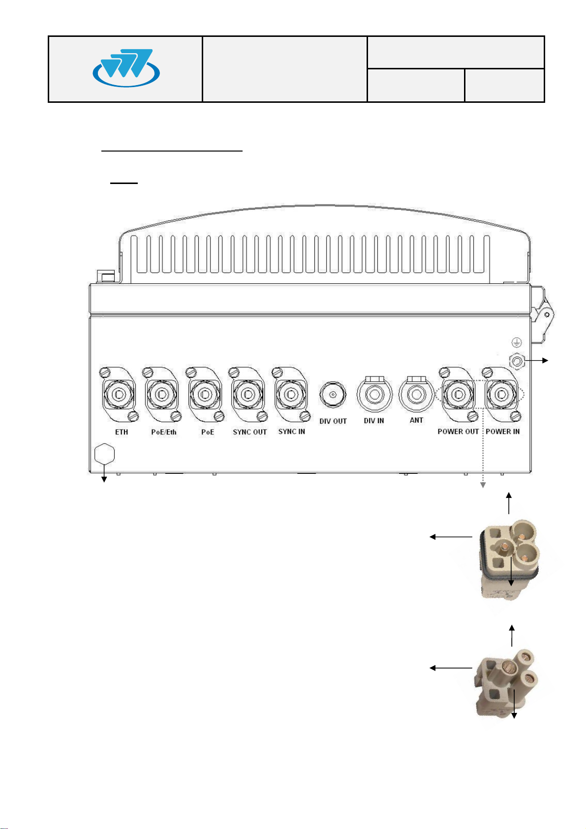
5.2. CONNECTORS
• 1.- Terminal with the following meaning depending on the MBS Unit Power option:
- AC MBS Units: Neutral contact (N).
- DC MBS Units: Negative contact (-).
• 2.- Terminal with the following meaning depending on the MBS Unit Power option:
- AC MBS Units: Line contact (L).
- DC MBS Units: Positive contact (+).
• 3.- Power supply Earth contact.
• 4.- Pressure equalizer.
• 5.- Chassis Earth contact.
MANUAL
Date: 05/10/11 Page: 10 of 38
• ETH: Connector that allows Ethernet connection between MBS Units. It also can be
used as Maintenance Ethernet connector.
• PoE/ETH: Power Over Ethernet (IEEE 802.3at) connector. It provides power supply
(48 VDC) and Ethernet connection to a PoE radio link. It can be used as
Maintenance Ethernet connector if there is not radio link (Poe) connected.
• PoE: Power Over Ethernet (IEEE 802.3at) connector. It provides power supply (48
VDC) and Ethernet connection to a PoE radio link.
• SYNC OUT: Synchronism output connector. It provides synchronism to a second
MBS Unit through its SYNC_IN connector.
• SYNC IN: Synchronism input connector.
• DIV OUT: Output reception connector. It provides the receiver chain 2 to the next
MBS Unit through its DIV IN connector.
• DIV IN: Reception antenna connector (receiver chain 2). It is connected to an
antenna or to a MBS Unit DIV OUT connector (diversity 2).
• ANT: Transmission/reception antenna power connector (receiver chain 1).
• POWER OUT : Output power supply connector. It provides power supply to another
MBS Unit with the same Power Supply option.
• POWER IN: Input power supply connector (VAC or VDC).
01.01.00/1 Rev.1
MBS USER AND
Code: D148X01_DDS06
INSTALLATION
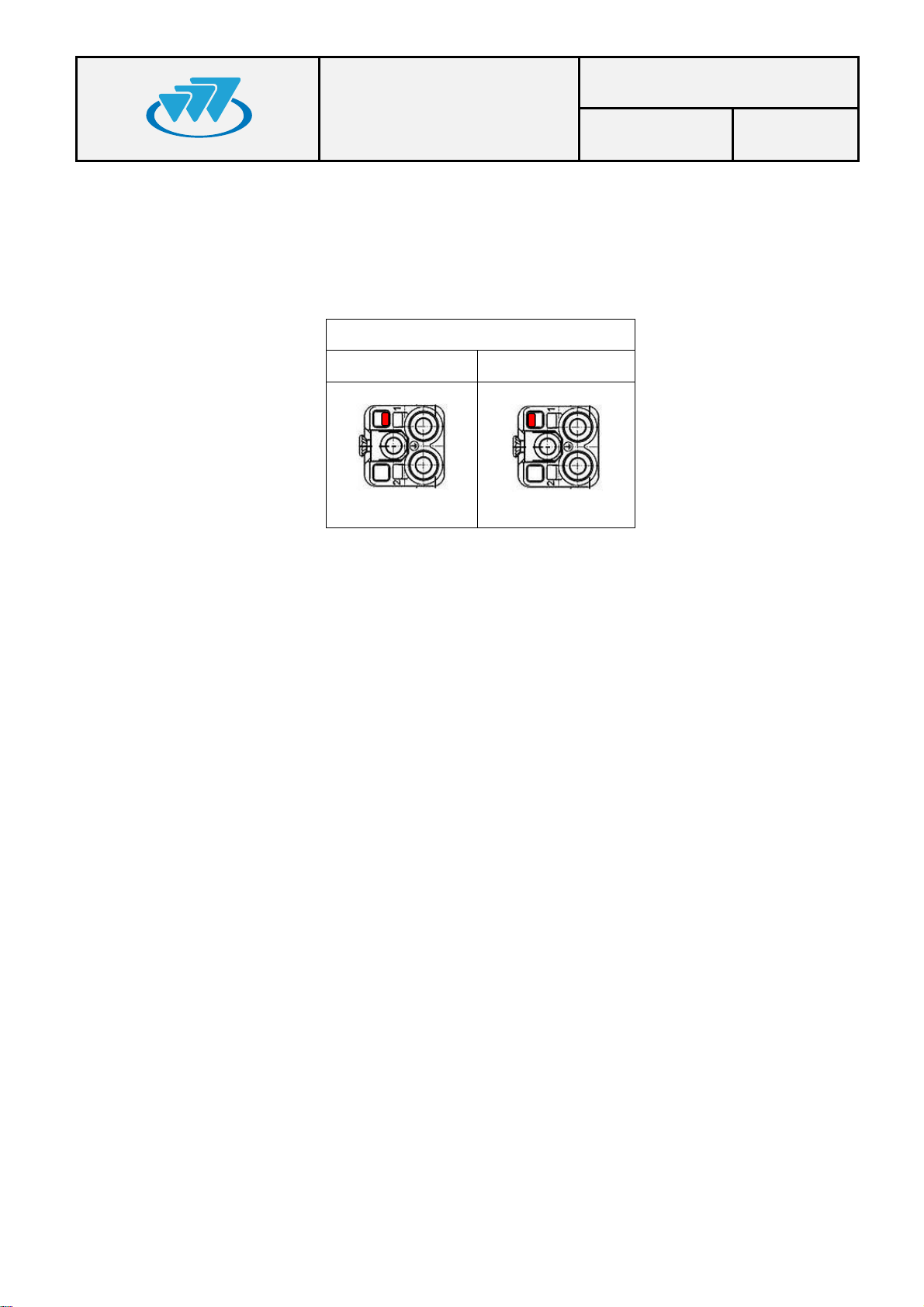
Note: POWER_IN and POWER_OUT connectors have a coding key to avoid wrong
connections; on the following table is showed the location of this coding key depending on
the MBS Unit power supply option.
External view of power supply panel connector
AC Power Supply DC Power Supply
MANUAL
Date: 05/10/11 Page: 11 of 38
Note: The amount of power delivered by both PoE and PoE/ETH connectors to the radio
links can not exceed 35 W in total.
01.01.00/1 Rev.1
MBS USER AND
Code: D148X01_DDS06
INSTALLATION
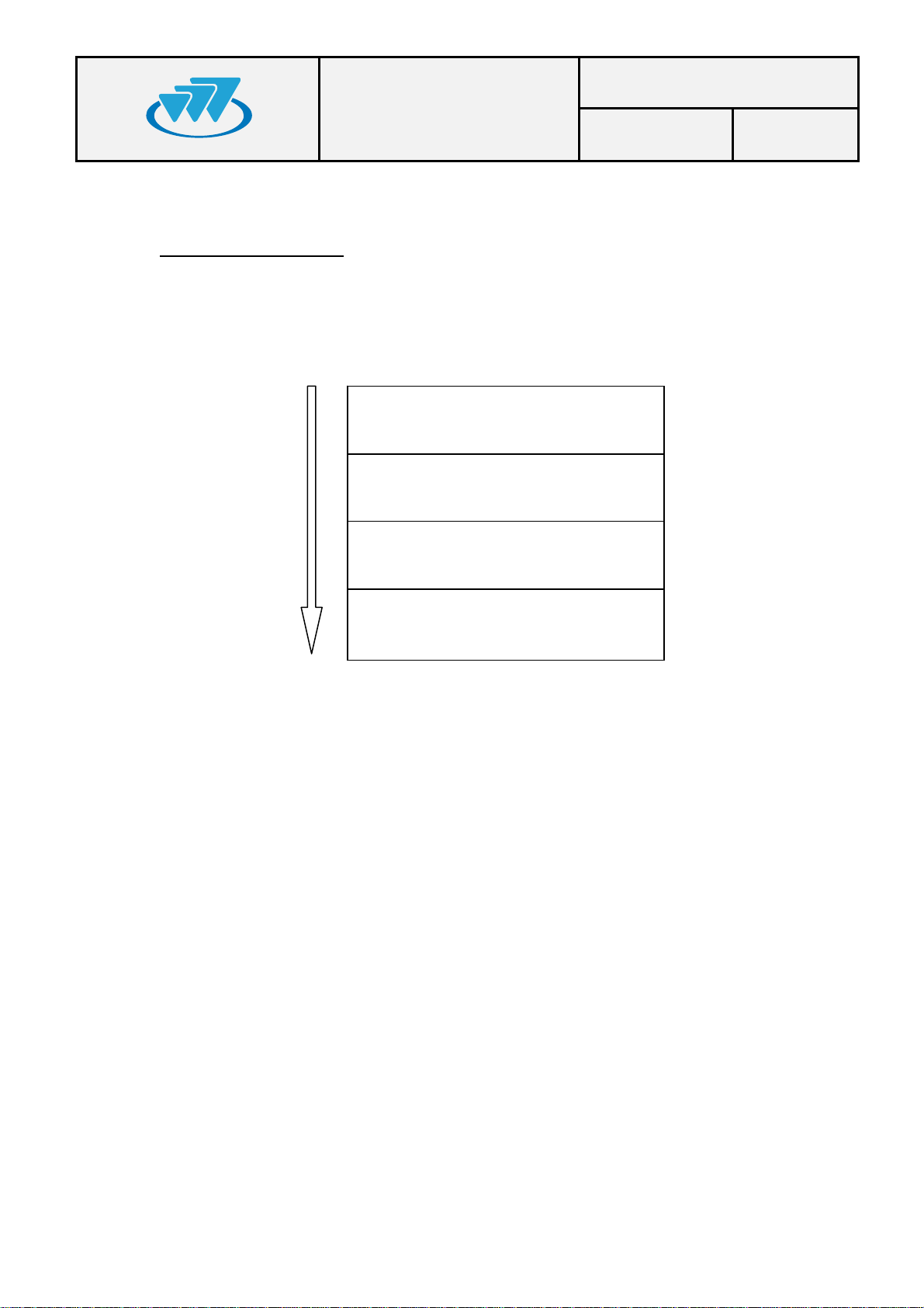
6. INSTALLATION GUIDE
The following recommendations must be followed before powering on the MBS Unit module.
Next diagram shows the steps to be followed to carry out the installation:
MANUAL
Date: 05/10/11 Page: 12 of 38
Verification of the necessary
Basic Pre-Configuration
Final location installation
Final Configuration/Verification
equipment
01.01.00/1 Rev.1
 Loading...