


1 DECLARATION OF CONFORMITY......................5
2 GUARANTEE ........................................................5
3 ABOUT THIS MANUAL.........................................6
4 FOR YOUR SAFETY.............................................7
4.1 GENERAL............................................................7
4.2 EXPOSURE TO RF ENERGY .................................7
4.3 ELECTROMAGNETIC COMPATIBILITY.....................8
4.4 OTHER WARNINGS ..............................................9
4.5 ANTENNA..........................................................10
4.6 AUDIO ACCESSORIES........................................10
4.7 MAINTENANCE ..................................................11
5 FIRST STEPS......................................................12
5.1 START-UP.........................................................12
5.2 WORKING MODES. ............................................13
6 BASIC USE..........................................................14
6.1 DISPLAY INDICATORS .......................................16
6.2 LED INDICATORS.............................................18
6.3 LIST OF EDITABLE CHARACTERS ........................19
6.4 DT-410 DESKTOP UNIT......................................20
6.5 MAIN SCREEN ...................................................21
7 MAIN MENU ........................................................21
TABLE OF CONTENTS
User Manual
8 BASIC FUNCTIONS............................................ 26
8.1 GROUP CALLS................................................. 26
8.2 INDIVIDUAL CALLS ............................................ 28
8.3 STATUS MESSAGES .........................................30
8.4 TEXT MESSAGES .............................................31
9 SPECIAL FUNCTIONS ....................................... 32
9.1 EMERGENCY CALLS .........................................32
9.2 WORKING MODES: DIRECT MODE .....................33
9.3 WORKING MODES: DMO-GATE MODE ............. 34
9.4 SECURITY........................................................35
9.5 NETWORK SELECTION...................................... 36
9.6 SUPPLEMENTARY SERVICES ............................37
9.7 DATA SERVICES...............................................38
9.8 GPS RECEIVER ...............................................38
9.9 GSM OPTION...................................................39
9.10 I/O PROGRAMMABLE OPTION ....................... 39
10 OTHER FUNCTIONS ..........................................42
10.1 CONTACTS PHONE BOOK ............................. 42
10.2 CALL HISTORY.............................................42
10.3 DISPLAY OPTIONS........................................42
10.4 LANGUAGES................................................43
10.5 AUDIO SETTINGS......................................... 43
10.6 USING AUDIO ACCESSORIES ........................ 44
11 QUICK REFERENCE GUIDE..............................45
1
en

User Manual
en
2
User Manual
WASTE MANAGEMENT
The symbol means that the product must be taken to separate collection at the
product end-of life. Do not dispose of these products as unsorted municipal waste.
NOTE:
PowerTrunk Inc. is the subsidiary of Teltronic S.A. Unipersonal responsible for
business development, distribution and customer support for Teltronic’s Land Mobile Radio
products in North America. The company is headquartered in New York City. Teltronic S.A.
Unipersonal distributes the same products for Land Mobile Radio under different trademarks
and brand names in other regions of the world.
Although an effort has been made in order to provide the most accurate information in
this document, it is possible than in some sections, diagrams or screenshots appear
references to the brand names and trademarks used in other regions. This should not be
construed as a commitment on the part of PowerTrunk Inc. and/or Teltronic S.A.U.
PowerTrunk Inc. and/or Teltronic S.A.U reserves the right to revise this documentation
and to make changes to its content at any time, without prior notification.
PowerTrunk, PowerTrunk-T and the PowerTrunk and PowerTrunk-T logos are
registered trademarks of Teltronic S.A. Unipersonal.
3
en
User Manual
This
equipment
can be used in member states
of the European Union once
the corresponding administrative
licence is obtained.
en
4

User Manual
1 DECLARATION OF CONFORMITY
PowerTrunk Inc., as manufacturer of the product MDT-400 / DT-410, declares that the said
product complies with the essential requirements established in article 3 of the Council of
Europe Directive 1999/5/CE, dated 9th March, 1999.
2 GUARANTEE
POWERTRUNK INC. guarantees the replacement or repair, free of charge, of any products
that are found to have a manufacturing defect, in accordance with the general conditions of
the POWERTRUNK INC. guarantee.
Under no circumstance shall POWERTRUNK INC. be held responsible for problems or
damage caused by any accessory or auxiliary element that has not be supplied by or certified
by POWERTRUNK INC. Neither shall POWERTRUNK INC. guarantee the functioning of this
product with auxiliary equipment or accessories that have not been supplied or certified by
POWERTRUNK INC.
5
en
User Manual
3 ABOUT THIS MANUAL
Welcome!
Thank you for purchasing this PowerTrunk MDT-400 or DT-410 device.
TETRA’s most advanced services and a wide range of options and accessories will help you
obtain the best performance from mobile communications in your work.
This manual will show you how easy it is to use the main features of your new TETRA
terminal. You will learn how to make a group call, an individual call, how to send status
message or how to edit a text message and send it to one or several users.
Before using the equipment, please read this manual carefully.
In addition to instructions on how to handle the device, you will
also find safety information, among which the
international guidelines on exposure to radio frequency.
Please keep this manual at hand for future reference.
For further information, contact your service provider.
At the end of this MDT-400 and DT-410 manual, you will find a Quick Reference Guide. In
addition, each unit is supplied with an Installation Guide.
en
6

User Manual
4 FOR YOUR SAFETY
4.1 General
PowerTrunk has obtained official approval for a wide range of accessories for MDT-400 and
DT-410 equipment: antennas, audio accessories, etc. These accessories have undergone all
type of tests to ensure their suitability and safety for the use they have been designed for,
either vehicle use (MDT-400) or desktop use (DT-410). We do not recommend the use of nonhomologated accessories.
For your safety, only have your equipment and accessories repaired by personnel authorised
by PowerTrunk. An incorrect installation (MDT-400 / DT-410 Installation Guide) or repair could
be dangerous and will render your guarantee void.
The equipment has been designed to fulfil the applicable compliance regulations.
The equipment complies with Part 15 of the FCC Title 47 of the Code of Federal Regulations.
Operation is subject to the condition that this device does not cause harmful interference.
The equipment complies with the applicable Part 90 of the FCC Title 47 of the Code of Federal
Regulations.
4.2 Exposure to RF energy
Your MDT-400 / DT-410 equipment, together with the accessories for which PowerTrunk has
obtained official approval, have been designed and manufactured so that they do not exceed
the limits of exposure to radio frequency energy established in international guidelines.
These guidelines, resulting from periodic scientific research by independent organisations,
have considerable safety margins to guarantee personal safety, regardless of the age or
health of the subject.
7
en
User Manual
MDT-400 / DT-410 is restricted to occupational/controller use to safety FCC RF
energy exposure limits. This radio is NOT authorized for general population.
Use only accessories and antennas approved by PowerTrunk. Use of non-approved
accessories and antennas may exceed FCC RF energy exposure limits.
4.3 Electromagnetic compatibility
Most electronic devices can suffer from electromagnetic interference unless they are
conveniently screened, designed or configured for electromagnetic compatibility.
To avoid these compatibility conflicts, it is necessary to respect current local regulations. This
equipment complies with the requirements of Council Directive 89/336/EEC on
electromagnetic compatibility, as well as Council Directive 95/54/CE regarding motor-vehicle
installations.
Vehicular Installation
The MDT-400 / DT-410 terminal must be supplied with a continuous
nominal 12V voltage in equipment terminals (minimum 10.8V,
maximum 15.6 V).
It must be taken into account that some mobile digital devices may interfere with hearing aids
or other medical devices. If this interference were to occur, please contact your service
provider or consult with the manufacturer of the hearing aid or medical device.
Using two TETRA devices with antennas in close proximity may cause mutual interference. If
this were to occur, separate the antennas until the interference disappears.
en
8
User Manual
Warning: Burns may be suffered if the bare part of the antenna is
touched during radio equipment transmissions.
Long periods of transmission may cause the rear part of the
equipment, where the power amplifier radiator is located, to reach a
high temperature.
4.4 Other warnings
Vehicles
RF signals may affect motor vehicles’ electronic systems if they are not properly installed or
well protected. For more information, check these aspects of your vehicle or the equipment
you have added with their manufacturers.
MDT-400 equipment has been approved in conformity with Directive 95/54/CE to guarantee
safety in vehicle installations, due to radio equipment transmissions affecting the vehicle’s
electronic systems: electronic ignition systems, brake control (ABS), traction or speed control
and onboard computer systems.
For correct installation of the equipment, please follow the instructions given in the MDT-400 /
DT-410 Installation Guide. Avoid using the area above the airbag or the area where it will
inflate. Airbags inflate with great force and the equipment could be projected forward and
cause serious injuries to vehicle occupants.
Potentially explosive environments
Disconnect the equipment when you are in an area with a potential explosion hazard and
comply with all notices and instructions.
Areas with a risk of explosions are often (although not always) indicated. Amongst these are
fuel filling areas (Ship decks, petrol stations, installations used for storing and transporting fuel
or chemical products) vehicles that use LPG and areas where the air contains particles such
9
en

User Manual
as grain, powder or metal particles.
Sparks in these areas can cause explosions or fires, with the resulting risk of injury and even
death.
Driver safety
Check the laws and regulations on using mobile phones and radiotelephones in the area
where you are to drive and always abide by them. While driving, concentrate all your attention
on driving and always have your hands free to manoeuvre the vehicle.
As a precautionary measure, whenever possible, park off the road to make or receive a call.
Programming
The equipment must always be programmed using a version of the programmer that is
compatible with the version of firmware.
4.5 Antenna
1. Do not use the equipment without an antenna.
2. To guarantee safety compliance, always use antennas validated by PowerTrunk.
3. Never use the equipment if the antenna is damaged. If a damaged antenna comes into
contact with the skin, it may cause burns.
4.6 Audio accessories
1. Only use accessories approved by PowerTrunk.
2. Follow the guidelines for fitting audio accessories in the MDT-400 / DT-410 Installation
Guide.
en
10

User Manual
4.7 Maintenance
The following recommendations will help you to increase the service life of the equipment and
maintain the guarantee coverage:
1. Do not install the equipment in dirty, damp or dusty locations. It is recommended to install
it out of direct sunlight and away from sources of heat. High temperatures can reduce
the service life of electronic components and deform or melt some plastics.
2. Any liquid spilt on the equipment can cause serious damage. If this occurs, consult your
authorised Technical Service.
3. Use a soft damp cloth for cleaning the outside surfaces. Never use chemical sprays or
abrasive cleaning products.
4. Do not obstruct or cover the ventilation holes of the DT-410 office unit.
5. Do not store the equipment in cold places. When the device warms up, there may be
condensation inside that could damage the electronic circuits.
6. Protect the equipment from impacts or being dropped. Circuit boards and more sensitive
mechanical components may get broken.
7. If you observe an error indication on the equipment screen that prevents it from working
normally, consult your service provider.
8. Do not open the equipment or try to modify it in any way. There are no user-serviceable
parts inside and removing the cover will expose you to electrical shocks and other
hazards. Any attempt to open the equipment and manipulate it in any way will render
your guarantee void.
9. Do not insert objects into the DT-41 0 desktop unit casing slo ts, as they could come
into contact with high voltage and cause shocks, fires or unit failure.
10. Do not place heavy objects on the equipment or on its power cable. A damaged cable
could cause shocks or fires.
11. Only use the power cable supplied with the equipment. To avoid shocks, the DT-410
must be earthed.
12. Disconnect the equipment antenna when there are storms, to avoid lightening damage.
11
en
User Manual
5 FIRST STEPS
5.1 Start-up
In the case of the DT-410, switch on the equipment with the main switch at the back of the
device.
1. Keep the key pressed to switch the equipment on or off.
2. On starting-up, it will display a welcome message (which can be configured by
programming). The software version of the equipment and the user’s name and address
will also be displayed for a few seconds.
3. If the equipment requests a PIN, enter the 4-digit code (by default the code is 0000),
which will appear on screen as ****, and press OK. It is recommended to change this
code for a safer one that you are able to remember.
4. If the user does not enter a correct PIN code after a number of permitted tries (which can
be configured, 3 attempts by default), the equipment will be locked until the personal
unlocking code - PUK - is entered (a 10-digit code). This code is provided by your
Service Provider.
5. When switching off the equipment, it will display a switch-off message and an acoustic
warning.
In the case of the DT-410, once the equipment has switched off completely at the front, you
can proceed to turn off the main switch at the rear.
en
12
User Manual
5.2 Working modes.
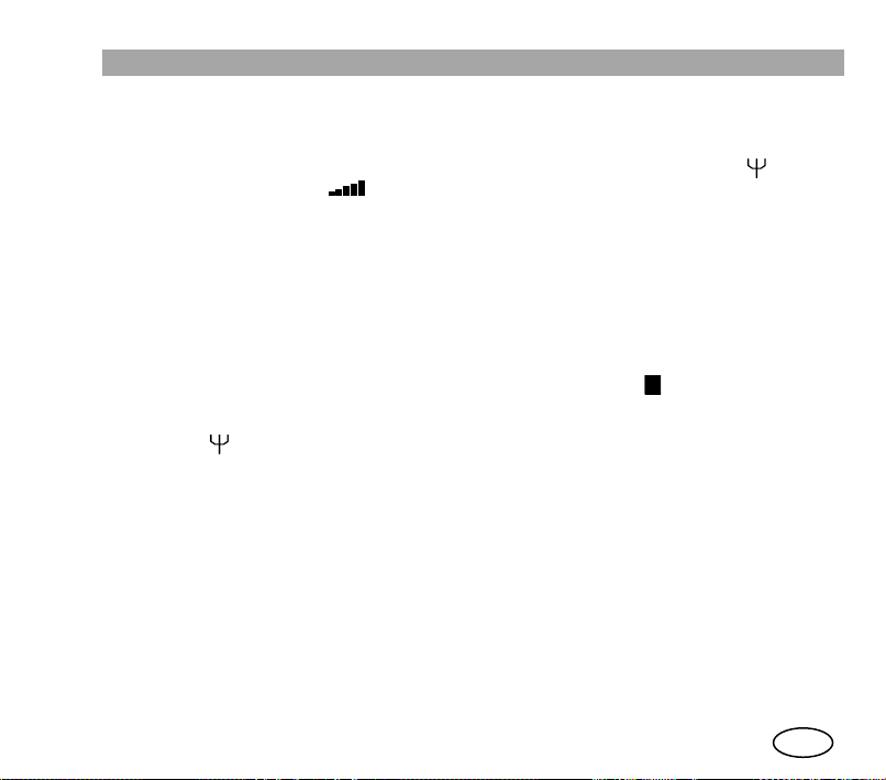
1. There are three working modes: network mode (V+D), direct mode (DMO) and DMOGATE mode. In network mode (V+D), the equipment will be operational when the system
has been successfully registered. Then the display will show the symbols (Valid
network indicator) and (signal level indicator).
2. During the system registration and network access process, the SVC LED will be lit up
continuously in red, and when a valid network is found it will flash and try to register into
it. When the register is complete, a characteristic programmable acoustic signal will be
heard, the SVC LED will turn green and the screen will display the message “In service”.
If the equipment is unable to access a network, the display will show “No service” and the
SVC LED will stay red. Even if the equipment has not registered, it is possible to access
the Main Menu, to select the Direct working Mode, for example, without need for
infrastructure.
3. In DMO mode, the SVC LED will be green and the symbol (Direct mode active
indicator) will be displayed in the symbol line of the display (Upper line). In this mode, the
symbol (valid network indicator) is not displayed.
4. If the equipment has the DMO-GATE option available, this working mode can be
selected, which will enable the transfer of group calls from the network to terminals in
DMO mode and vice versa.
5. The equipment may be configured to start in any of the available modes or it is possible
to change the mode manually through the “Working modes” menu.
D
13
en
User Manual
6 BASIC USE
This manual is common for both equipment models: the MDT-400 mobile equipment and the
DT-410 office unit.
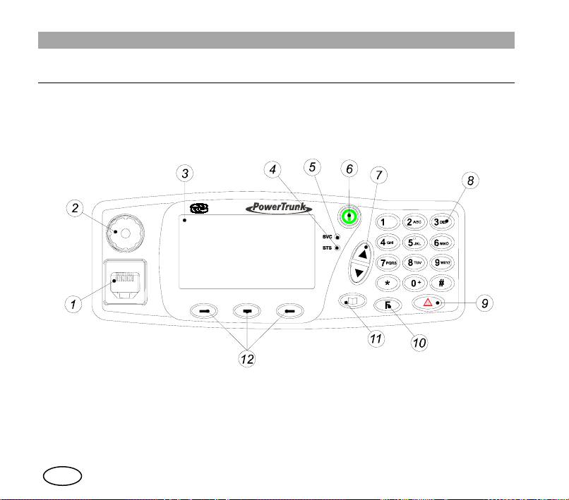
Both models have the same front panel, described below.
The MDT-400 can also be used without front for data applications using the PEI protocol and
audio control through the 600-ohm interface. If your equipment has this configuration, consult
with your Service Provider to learn about the services available and how to access them.
14
en
User Manual
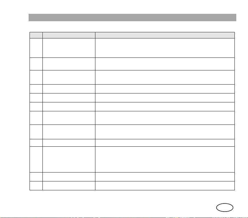
No. Description Observations
Microphone
1
connector
2 Volume control
3 Screen
4 STS LED Indicator Call status indicator.
5 SVC LED Indicator Service indicator.
6 ON/OFF key Key to switch on / off
7 Navigation keys
Alphanumeric
8
keyboard
9 Emergency key Starts / cancels the emergency call.
10 Function key
11 Menu key Access to Main Menu.
12 Soft keys Press to select the corresponding on-screen option.
Connector for handheld Microphone or Micro-loudspeaker or
desktop microphone (DT-410).
Connector for the programming cable.
Adjusts the volume level. Screen adjustment Contrast,
Volume audio and Volume tones.
Alphanumeric display 4 x 16, line of symbols and line of ‘soft
keys’.
Navigation by menus/submenus and their options.
Editing phone books / messages.
For entering number and characters. (See section 6.3)
Combined with other keys, it enables rapid access to certain
functions.
By continuous pressing, it changes the working mode
(TETRA V+D<-> DMO)
15
en

User Manual
6.1 Display indicators
The on-screen indicators display information about the operation of the equipment:
Icon area
Text area
Soft keys area
Symbol Description
Call established
Signal intensity (RSSI) or level of coverage indicator
Valid network (Only in V+D network mode)
Emergency call established (steady).
Flashing if the call is being set up
cid:
ima
ge0
02.
gif
Message received (steady). Flashing when a message is being sent.
Discrete mode active. Converts a semi-duplex incoming call with direct signalling to
on/off hook signalling.
All tones off
.
en
16

GRP/BRD/PRV
/PHN/PBX
GPS position valid (steady). Flashing if GPS position is not valid.
F
Steady: Terminal registered in encrypted mode. Encrypted call.
AABBCC // aabbcc
Type of voice call selected: group (GRP), private (PRV), broadcast (BRD), phone
(PHN) or through telephone exchange (PBX).
Will only be displayed if the GPS option is installed in the MDT-400 unit.
Direct mode (DMO) activated.
Data packet connection. Steay if the connection has been established. Flashing if data
transfer is under way.
Call diversion activated.
Inclusion call activated.
Access to sequential functions with
Messages received box full
Flashing: Terminal registered in encrypted mode. Clear call.
Text editing screen
GSM call established (steady). Flashing during call establishment.
Will only be displayed if the GSM option is installed and activated.
Active group scan (groups in listening mode).
DMO-GATE mode.
Presence of a DMO-REP detected in the DMO frequency selected.
When the terminal has the E2EE module (End to End Encryption) active:
Active call with E2EE Encryption.
Clear call active.
Migration. Terminal registered in a different network to its own local one.
TxI (Transmit Inhibit) functionality.
Transmissions temporarily inhibited (except emergency call).
F
key.
User Manual
17
en

User Manual
6.2 LED Indicators.
LED indicators display information about equipment operation:
SVC LED
LED status Function
Off Equipment not operational.
Red Equipment not in service (no network registered).
Flashing red Equipment in the process of registering.
Green Equipment in service (Registered on the network).
Flashing orange Equipment in programming mode
LED status Function
Off No call being carried out.
Red Equipment transmitting a call. PTT pressed (semi-duplex
Flashing red Request or end of transmission.
Green Equipment receiving a call.
Flashing green Call in progress, no one transmitting.
Orange Call being established.
If the two LEDs (SVC and STS) are orange, this indicates an error. If this occurs consult your
Service Provider.
Equipment operational (DMO).
STS LED
call) or until the communication is over (duplex call, only in
TMO –trunking mode-).
en
18

User Manual
6.3 List of editable characters
The following table displays the characters available for editing texts on the MDT-400 and DT-
410.
Keys
1 2 3 4 5 6 7 8 9 10 11
Space
1
2 ABC A a B b C c 2 Á á À à Â â Ã ã Ä ä Å å Ç ç
3 DEF D d E e F f 3 É é È è Ê ê Ë ë
4 GHI G g H h I i 4 Í í Ì ì Î î Ï ï
5 JKL J j K k L l 5
6 MNO M m N n O o Ñ ñ 6 Ó ó Ò ò Ô ô Õ õ Ö ö
7 PQRS P p Q q R r S s 7
8 TUV T t U u V v 8 Ú ú Ù ù Û û Ü ü
9 WXYZ W w X x Y y Z z 9
0 +
. 1 , & $ @ # ¿ ? ¡
! : ; _ “ ’
+
- { 0 } = < * > ÷ / \ ( ) [
]
Screen characters
Number of times to press the key
19
en

User Manual
6.4 DT-410 desktop unit
The DT-410 desktop unit integrates the radio equipment with a built in power supply and an
internal loudspeaker to optimise the space needed for fixed installations.
The desktop unit has not been designed to bear he avy
weights; therefore heavy objects should not be placed
on top of it.
Not place heavy
objects on the rack
Its menus and operation are the same as the mobile MDT-400 equipment, with the foll owing
exceptions:
If the DT-410 is controlled via PEI (E.g., from a PC application), only one screen is displayed,
enabling two options:
- Return to manual control of the equipment, pressing soft key ‘MMI’
- Enable or disable the internal loudspeaker, selecting Loudspeaker Yes or No.
The volume control and the on/off switch remain active.
en
20

User Manual
6.5 Main screen
The main screen is that of Voice Calls (in V+D network mode) – Group mode.
The equipment will be prepared to press PTT (Press-to-talk) and directly launch a call to the
group selected.
The basic information viewed on this screen consists of the range the selected group belongs
to, the name of the group and its status.
The soft key ‘Mode’ (Lower right-hand side of the screen) enables selection between other
types of call (private, telephone, PABX). If desired, automatic return to the preferred type of
call can be programmed after a few seconds.
7 MAIN MENU
To access the Main Menu, press the key .
The Main Menu is cyclically organised and the different screens can be accessed using the
navigation keys: .
The soft keys can enable or disable menu options, access submenus and return.
Some screens may not be displayed, depending on the configuration of your equipment.
To avoid certain configurations being accidentally modified, some functions can be restricted
by programming. The menus/functions that can be restricted are phone books, call regi ster,
operating modes, accessories (In configure audio), sending status messages and sending text
messages.
21
en

User Manual
Press the menu
to access Main
Menu
key
GRP
Phone Book
Exit OK
GRP
Messages
Exit OK
GRP
Call
history
Exit OK
Use the
shift keys
to navigate
the menu
GRP
Operating
modes
Exit OK
GRP
Working
modes
Exit OK
GRP
Audio
Settings
Exit OK
GRP
User
Settings
Exit OK
Shows the last call
display activated
en
22

User Manual
1. PHONE BOOK
Private
Æ Add PSTN Æ Add
Erase Erase
Mem status Mem status
Edit Edit
Æ Add PABX Æ Add
Group
Erase Erase
Mem. status Mem status
Preferred GRP Edit
2. WORKING MODE
V+D
DMO
Gateway
GSM
3. AUDIO SETTINGS
Audio volume
Keypad tones On/Off
Accessories
Handset Call-in tones On/Off
Hands free kit Call-out tones On/Off
Auto TX permission On/Off
PTT detection RX permission On/Off
Received msg Off/Norm
Ringing tone Tone1… 10 Sent message On/Off
Tone volume +/-
Æ +/- Active tones On/Off
Æ Standard Control tones On/Off
al/High
23
en

User Manual
4. USER SETTINGS
Language Screen
Brightness
PIN code
Change PIN Contrast
5. OPERATING MODES
Area selection Local area TxI mode On / Off
Areas 1..14 Discrete mode On / Off
Wide area
6. CALL HISTORY
Dialed
Received
Missed
Erase all
7. MESSAGES
Status
Send Outbox
Erase status New
Configure
Erase Inbox
Erase Outbox
en
Æ PIN Request Negative
Æ Read Text Æ Inbox
24
Æ Backligth

User Manual
8. ENCRYPTION (optional)
This menu will only be displayed if the E2EE option has been installed.
Set Date & Time
Time
Select PLAIN/CRYPTO
Prefer PLAIN
Use default
Factory Reset
Key Set Check Value
Info Security Proc.
Info Crypto Module
9. GPS INFO (optional)
This menu will only be displayed if the GPS option has been installed. The following
information could be accessed only if GPS position has been provided.
Latitude – Longitude
Speed (Km/h, mph) – Course – Deviation.
Time – Date
Æ Date
Æ Prefer CRYTO
Æ Fact. Reset
Pwd
Æ Key Set CV
25
en

User Manual
8 BASIC FUNCTIONS
8.1 Group Calls
Group calls will enable you to communicate with a group of users that are allowed to
participate in the communication. Select GRP mode with the soft key ‘Mode’.
A group call is always semi-duplex with direct signalling: the group selected on screen is
directly connected by pressing PTT, and it is not possible to listen and speak at the same time.
The groups are organised in ranges (or folders). Each range can have several groups and
their distribution is established by programming.
To select the range and group, use the navigation keys .
Alphabetic search will only be applied to the groups included in the selected range.
Once the user has selected one of the ranges, it will only be possible to move through the
groups included in that range. The groups will be sorted alphabetically within each range. The
selected range / group is displayed on the screen.
To change the range, press the soft key ‘Range’.
When a group has been selected, its status will be displayed on screen for a few seconds. The
call to this group will proceed if the group is available. If it isn’t, pressing PTT will display the
message “Non-valid group”.
The user must keep the PTT key pressed to send the call, and the rest of the users in the
group will listen directly.
The STS led will turn red (transmission) or green (reception).
en
26

User Manual
The speaker’s identifier (or name if available in the phone book) will be displayed on screen.
The group call is directly received, with no action necessary on the part of the user. The
equipment will inform the user that a group call has been received with a short alert tone and
the name of the user speaking at any given moment as well as the name of the group will be
displayed on screen.
The call will be disconnected by pressing the soft key ‘Hang’ or the AUX key of the handheld
microphone or simply by releasing PTT and waiting for the system to disconnect.
The group call will be finished by the system if it detects that for a certain time no user has
requested permission to transmit.
Any other user can leave the call using the same procedure, although it will continue for the
rest of the users.
It is possible to configure the groups to listen by programming, so you will receive all the calls
in this status.
27
en

User Manual
8.2 Individual calls
An individual call is a call between 2 users. No other user will listen to your call. It can be
made to numbers on the TETRA network (private calls) or to numbers on the external
telephone network (PSTN or PABX telephone calls).
MDT-400 / DT-410 will enable you to make the following individual calls:
- Semi-Duplex w ith direct signalling: The caller has permission to speak first. It is not
possible to speak and listen simultaneously.
-
Semi-Duplex with “hook” signalling: The receiver must answer (unhook) first. It i s not
possible to speak and listen simultaneously.
-
Duplex: The signalling is hook (the called party must answer first). It is possible to speak
and listen simultaneously. It is not necessary to press PTT to speak.
To make a private semi-duplex call:
- Enter the number of the person you wish to call or select it from the phone book.
- With the soft key ‘Mode’ (lower right-hand part of the screen) select the type of call you
wish to make (PRV, PSTN, PABX).
-
If the call you wish to make is direct signalling, press the PTT button and speak directly.
When you wish to stop speaking, release the button. Then your interlocutor can carry out
the same operation: press PTT and talk.
- For semi-duplex calls with Hook signalling, start the call by pressing the AUX button on
the hand-held microphone. This option must be enabled by progra mming. The user must
accept (unhook) the call first. When the call has been established, the user who wishes to
speak must keep PTT pressed.
- There are two ways to finish any type of private call: By pressing the AUX button on the
hand-held microphone or by the soft key ‘Hang’.
If Discrete Mode is active ( ), a semi-duplex incoming call with direct signalling will be
converted to hook signalling.
en
28

User Manual
To enable this mode, go to the Operating Modes → Discrete Mode menu. This option must
be previously enabled by programming.
To make a duplex call:
- Enter the number of the person you wish to call or select it from the phone book.
- With the soft key ‘Mode’ (lower right-hand part of the screen) select the type of call you
wish to make (PRV, PSTN, PABX).
- Start the call by pressing the soft key ‘Call’.
- During the establishment of the call you will hear a call tone. Wait for the caller to take
the call. At that moment, the call is established and it will be possible to begin speaking
without having to press the PTT button.
- Either user can disconnect the call by pressing the AUX key of the handheld microphone
or by the soft key ‘Hang’.
Accessing the Call history submenu from the Main Menu, you can repeat a call recently
made or answer a received or missed call.
Accessing the Messages submenu from the Main Menu, it is possible to read the status
messages received (Read the status messages option) and use the phone of the sender
(Answer a selected message option or pressing PTT or AUX on that screen).
Accessing the Messages submenu from the Main Menu, it is possible to read the text
messages received (Inbox option of the text messages) and use the phone of the sender
(Phone Back option in the Options of a selected message).
29
en

User Manual
8.3 Status messages
The MDT-400 / DT-410 allows you to send status messages to individual and group
addresses: “Call Back”, “Urgent request” and “Emergency”. These are standard messages
that can be enabled or not by programming
It is also possible to send messages predefined by the user by programming. They are
messages whose number code and associated text are defined by the user.
In the Messages submenu of the Main Menu, select the option “Status”.
You can send status messages to individual addresses (TETRA private addresses or
telephone addresses) or group addresses stored in the phone book, or directly dial the
individual destination address.
Once the destination has been selected, press soft key ‘Send’.
When the message is received in the infrastructure, this will send a confirmation “Message
sent” or inform of “Failed sending” to the equipment.
To send a status message rapidly to a predefined address (individual or group) press
F
+ + Digit 1 + Digit 2. This option must be enabled by programming.
The message number is indicated with
occupied by the message in the list. This can be consulted to know the place each one
occupies (Messages Menu in the Main Menu).
When a new status message is received, the equipment informs the user by means of an
information screen that a message has been received and the symbol is displayed.
To read old status messages, select Status from the Messages submenu of the Main Menu,
which contains the following options: Read, Send and Delete status.
*
digit 1 and digit 2 and it corresponds to the position
en
30

User Manual
8.4 Text messages
Another service that you will be able to carry out with your MDT-400 / DT-410 equipment is to
send text messages of up to 140 characters (160 if the destination address is a telephone
number).
You can write a new message using the text keyboard (Select Text/New in the Messages
submenu of the Main Menu), or select one of the messages stored in the out tray
(Text/Outbox).
Once the message is written or one is chosen from the outbox, select its destination address
as explained in section 8.3 (Status messages). Then press the soft key ‘Send’.
The equipment will indicate the result of the transmission with an information message.
When a new status message is received, the equipment informs the user by means of an
information screen that a message has been received and the symbol is displayed,
which informs that you have a new unread message.
In Text/Inbox, you can see all the text messages received, and in Text/Configure, you can
access the different parameters that can be modified in the text message service, such as
activation of delivery reports, for example.
MDT-400 / DT-410 enable the reception of text messages immediatel y. The characteristic
of this special type of message is that its content is displayed on the screen as soon as it i s
received.
31
en

User Manual
9 SPECIAL FUNCTIONS
9.1 Emergency calls
By keeping key pressed, an emergency call is begun, which has maximum
priority and will cancel any call being made at that moment.
This type of call can be configured by programming, and can be: private semi-duplex direct
call, group call, broadcast call, telephone call (PSTN, PABX) or status message.
It is also possible to configure the emergency call in DMO, being able to configure a different
call destination in V+D and DMO.
The emergency icon will be displayed flashing on the display.
If the equipment cannot establish the call or send the status message, it will continue trying,
unless the user cancels the call by pressing the emergency key again.
After a loss of service or equipment being switched off, the emergency call will try to be re-
established when the equipment is operational again if the parameter “Continue emergency
call” is enabled by programming.
If the emergency call is a voice call, there is an initial automatic transmission time (5 seconds
by default) for semi-duplex calls, without having to press PTT.
When this time is over, the user must press PTT to transmit as usual (if it is a semi-duplex
call).
This type of call can also be initiated by activating an external input (available in the rear
connector) to which, for example, an emergency pressure pad can be connected. Consult your
Service Provider about the availability of this option.
32
en

User Manual
It is possible to configure two additional codes – emergency codes – such as 112, 999 o r
others.
When the user enters these codes on the keyboard, the MDT-400 sends the emergency call
as programmed.
In addition, the sending of standard emergency message can also be configured (St atus code:
0) just before carrying out the event programmed for the emergency key.
Another possible configuration, only available by programming, is to define the PT T as priority
within the active call. This option enables the definition of priority users, who will be able to
interrupt the person speaking during a call in progress.
9.2 Working modes: Direct mode
This special mode, called DMO, enables you to communicate directly with other TETRA
equipment without needing to use a network.
To access DMO mode, select the Working Modes/DMO menu, or press the rapid access
configured in your equipment for this function.
In DMO mode, you may carry out group calls and individual calls. The emergency button will
also be available, with which you can carry out a call with maximum priority (pre-emptive), as
detailed in the previous section.
Each group programmed to work in DMO mode has a frequency associated, so that a change
of group implies a change of frequency and only equipment with the same group selected will
be able to communicate with one another in this working mode.
Individual calls will be carried out using the active channel, i.e., the one associated to the
selected group.
33
en

User Manual
Group calls
To start a group call in DMO mode, select the group with the navigation arrows keys and press
PTT. The operation is similar to a group call in network mode.
Individual calls
To start a private call, first dial the destination number or select it from the phone book. Then
press PTT.
9.3 Working modes: DMO-GATE mode
This section describes the DMO and V+D functionality supported by MDT-400 working in
DMO-Gateway mode.
To access DMO-Gateway mode, select the Working modes/Gateway menu or press the
rapid access F + #.
In this working mode, the MDT-400 will act as a bridge in the communications between
equipment in DMO mode and the infrastructure.
All the supplementary services are disabled in this working mode. The Data Packet
Transmission service is also disabled, as is the sending and receiving of status and text
messages, by both the user and the application.
DMO-GATE enables communication between DMO and TMO in end to end encrypted mode.
The only phone book that exists in the equipment working in this mode is an assign ment table
where a group configured in V+D is matched to another group configured in DMO.
The same groups stored in the group phone book are used.
The programming tool creates the DMO - V+D matching.
The scanning lists are not enabled.
34
en

User Manual
All the audio and voice signalling is disabled in this working mode, except the tones for
establishing, maintaining and ending calls.
9.4 Security
The equipment has the following security services:
- PIN code
From the User settings/PIN code menu you can enable or disable the request for a PIN
code on turning on the equipment as well as modify this code.
- Authentication
MDT-400 / DT-410 supports the authentication of the radio equipment by the
infrastructure, which ensures that the user trying to connect to the network has a valid
permission to do so.
This service requires the equipment to have its corresponding code installed.
To change the code you must contact your Service Provider.
- Remote enabling / disabling of the equipment.
The MDT-400 / DT-410 can be enabled or disabled from the infrastructure, throu gh the
air interface.
This disablement can be temporary or permanent.
Recovery of a temporally disabled unit is carried out by the infrast ructure. In the case of
permanent disablement contact your Service Provider to have the equipment put back
into operation.
35
en

User Manual
- Air Interface encryption (optional)
This service protects communication between the radio equipment and the infrastructure
from possible undesired listening in. This encryption is only carried out in networks that
support this service.
The encryption algorithms for the Air Interface encryption which a re avai labl e i n the MDT400 are: TEA1, TEA2, TEA3.
- End-to-end encryption (optional)
This functionality is particularly interesting for those users who regard thei r transmissions
as very sensitive, and whose Security Policy requires all such data to be appropriately
encrypted whilst in transit between the end terminals in any system.
End-to-end encryption addresses these concerns by encrypting data within the
transmitting terminal, and only decrypting it within the receiving terminal(s). The plain text
user data is never exposed within the infrastructure.
Batteries and accumulators
If your terminal includes End to End Encryption option, it may have a
3.6 V lithium battery, with low self-discharge rate.
In case you need to extract the battery from the terminal, consult
your official dealer.
Don’t dispose of these products as unsorted domestic waste.I
To install or change the codes you must contact your Service Provider..
9.5 Network selection
Whenever you turn on the equipment, it will always try to register in your programmed local
network. The Operating Modes submenu in the Main Menu includes the ‘Netwok selection’
36
en

User Manual
option, provided that this option has been pre-programmed. You may choose a new work
network from the list of permitted networks available.
9.6 Supplementary services
The following TETRA supplementary services are also available in your MDT-400 / DT-410
terminal (none of them requires any additional action on the part of the user in the Options
menu):
- Late entry:
This supplementary service enables the device to join a group call that is already in
progress.
- Ambience listening:
Ambience listening enables a control centre or dispatcher to listen in to a unit and hear
what is going on around it, without giving the user any visual or acoustic indication of this
call. Ambience listening is only possible is the unit is not alread y occupied with another
call. Likewise, the supplementary ambience listening service does not prevent the
affected user from making or receiving other calls.
- DGNA: Dynamic group assignment. Both individually and group addressed DGNA
groups are supported
- Fallback mode (local mode):
MDT-400 / DT-410 support working in a cell in local mode (disconnected from the rest of
the system) indicating this situation to the user through the MMI.
The equipment will avoid registering in local mode cells unless there is no other available
cell. The services available in this mode will depend on the system configuration.
Consult your supplier about other services and special options available.
37
en

User Manual
9.7 Data services
MDT-400 / DT-410 include a data packet service (mono and multislot) based on IP version 4.
While the data packet context is active, the symbol appears in the icon area of the
display.
The MDT-400 / DT-410 supports AT and TNP1 commands of the PEI protocol for connecting
to external devices and the remote control of the equipment.
For more information about these services, consult your Service provider.
9.8 GPS receiver
The MDT-400 can incorporate an internal GPS receiver that will enable you to know your
exact position at all times and transmit your position to a base station.
If the equipment has this option, you can access this information through the GPS info menu
from the Main Menu.
By programming, you can configure different parameters for sending GPS positions to a
central application to manage this location information.
Consult you service supplier about how to configure your equipment for this service.
Batteries and accumulators
If your terminal includes GPS option, it may have a 3.6 V lithium
battery, with low self-discharge rate.
In case you need to extract the battery from the terminal, consult
your official dealer.
Don’t dispose of these products as unsorted domestic waste.I
en
38

User Manual
9.9 GSM option
The MDT-400 can incorporate an internal GSM module.
By default, the equipment will work with the TETRA network, and when it detects that it is not
possible to operate under TETRA, it automatically switches (if the equipment is configured in
this way) to GSM mode.
It is also possible to select GSM mode through the menu, accessing the Work ing mode
submenu from the Main Menu. This screen shows the options V+D, DMO, DMO-GATE and
GSM, not allowing direct changes between GSM <-> DMO.
While the equipment operates in GSM, TETRA services will remain active: If TETRA calls are
received, they are rejected with the “User called engaged” cause. The messages received are
stored in the memory and can be consulted on returning to TETRA.
As soon as the equipment detects the recovery of TETRA coverage, it again returns to this
mode.
9.10 I/O Programmable option
This option can be chosen to replace the vehicle option installed by default.
When this option is enabled, the ‘I/O Programmable’ screen enables the selection of the
desired functions for each of the external lines of the rear connector.
It will be possible to access the programmable parameters in this option through the
programmer screen ‘Options \ Programmable I/O lines’.
By configuring these 4 input lines (IN1, IN2, IN3, IN4) and 2 output (OUT1, OUT2) it is
possible to configure the following functions:
39
en

User Manual
Control mute of an external device. Audio will be disabled during voice calls.
-
- Ignition c ontrol controls the switching off of the terminal dependi ng on the status of the
vehicle’s engine.
- Control of external horn relay enables the MDT-400 to activate an external relay for the
horn of the car or any other device.
This option is incompatible with the Control mute option.
- Line interfac e provides the terminal with a balanced audio input and output as well as
two additional basic signalling lines (one input line ‘E’ and one output line ‘M’).
This option is incompatible with the Control ignition option.
en
40

Inputs:
- Signal IN (IN4) Æ No function
Æ Line interface (wire E)
Æ Ignition control
Æ Another event
- Input 1 (IN1/PTT): Æ PTT external
Æ Another event
- Input 2 (IN2/AUX): Æ External AUX (disconnect the call and
begin a private hook call)
Æ Another event
- Input 3 (IN3/HANG): Æ External HANG (HANG UP)
Æ Another event
Outputs:
- Relay out (OUT1) Æ No function
Æ External horn relay
Æ Mute
Æ Another event
- Signal out (OUT2): Æ No function
Æ Line interface (wire M)
Æ Another event
User Manual
41
en

User Manual
10 OTHER FUNCTIONS
10.1 Contacts phone book
From the Phone Book menu you can configure your list of contacts. You can consult, add
new contacts, delete them or select them for making calls. You will access all the equipment
phone books:
- Private
Group
-
- Telephone (PSTN)
If you receive a call from any of the addresses corresponding to a contact stored in the phone
book, its name will be displayed on the screen.
MDT-400 / DT-410 supports “Scanning of priority groups” mode. If the scanning list is
active, this option will be displayed in the groups phone book, which enables the adding or
deleting of groups (up to 15) from the scanning list.
10.2 Call history
From this menu you can access the following options: calls Dialed, Recei ved, Missed and
Erase All call records.
10.3 Display options
In the User Settings/Display menu, you can select the desired brightness and cont rast of the
screen. You can modify it using the arrow keys or with the rotating switch.
By default the equipment is configured with an automatic backligth mode. The screen will
always be illuminated when a key is pressed or a call is received, and will remain lighted for
some seconds (time established by
en
- Telephone extension (PABX).
programming).
42

User Manual
10.4 Languages
The MDT-400 / DT-410 terminal has a programmable multilingual interface.
The User settings\Language submenu enables you to choose between the languages
available in the MDT-400 / DT-410. Using the arrow keys, you can select the language you
wish to use.
Consult your supplier about the languages available for your terminal.
10.5 Audio Settings
From the Audio Settings submenu, you can carry out the following actions:
- Select the predetermined audio profile.
- Modify the volume of the call sound.
- Select the call tone that will be heard when receiving a call.
- Select the message tone that will be heard when receiving a message.
- Select the accessories you wish to use.
- Enable / disable independently the following acoustic warnings:
o Keys.
o Control: service / no service tone.
o Call.
o Message received.
o Message sent.
o TX permission.
o RX permission.
o All tones.
You can also enable by programming the
Unread message tone.
43
en

User Manual
10.6 Using audio accessories
The user can select the configuration for audio accessories regardless of the default program
configuration.
Access Audio Settings submenu from the Main Menu and choose the option “Accessories”.
It is also possible to access this screen with a combination of rapid access keys: + 9 +
7.
If your equipment is the mobile MDT-400, you can choose between the following
configurations:
- Standard: Handheld microphone / Micro loudspeaker / Desktop microphone and
External microphone
Handset: Micro-telephone with PTT, used to maintain private calls
-
-
Hands free kit: Ambient microphone and External loudspeaker
- Auto: Ambient microphone & External loudspeaker & Mi cro-telephone with PTT. In this
configuration, the audio will switch from the hands free kit to the micro-telephone when it
is unhooked
- PTT Detection: Switch between Standard and Hands free kit automatically depending
of which PTT is being pressed
If your equipment is the DT-410 desktop unit, you can choose between the following
possibilities:
- Standard: identical configuration to the standard on the MDT-400
Handset: identical configuration to the standard on the MDT-400
-
Headphones: Micro-headphones and External loudspeaker
-
- Auto: identical auto configuration to that described for the MDT-400
If the handset or headphones are selected, using the menu you can also enable or disable the
external loudspeaker (‘Loudspeaker’ option in the Audio Settings submenu), thus enabling
the private conversation in progress to be heard by other people.
en
44

11 QUICK REFERENCE GUIDE
1. Fist microphone, handset or
desktop (DT-410) microphone
connector.
Programming cable connector.
2. Volume control
3. Display
5. SVC Service indicator.
Green: in service
Red: out of service
6. ON/OFF key
7. Navigation keys
9. Emergency key
10. Function key
11. Menu key
4. STS Call-state indicator 8. Alphanumerical keyboard 12. Soft keys
CHANGING WORKING MODE
MAKING DMO CALLS
Private calls
Mode
PRV
Group calls
Mode
Select
GRP
BRD(**)
(*) Available for the fist microphone accessory
(**) Available if programmed (contact your official dealer for more information)
Main Menu
Dial number or select
Select presence
check (On/Off) (**)
range/group
Press PTT
from phone
book
Go to 'Working Mode'
Press PTT
STS
red
Select 'DMO'
Press and hold
STS
PTT (to speak)
Release PTT
flashing
red
Press and hold
PTT (to speak)
Release PTT
(to listen)
Select 'V+D'
(to listen)
STS red
STS green
STS red
STS green
Press 'End'
or AUX (*)
Press 'End'
or AUX (*)
The symbol
is displayed
SVC indicator green
Radio connects to
network
D
en

User Manual
POWERING ON AND OFF
Keep key pressed for a few seconds.
MAKING V+D CALLS
Semi-duplex private calls
Mode
Dial number
PRV
or select
Duplex private calls
Mode
PRV Dial number
or select
Telephone calls
Mode
PHN Dial number
PBX
or select
Group calls
Mode
Select
GRP range / group
BRD(**)
from phone book
Press PTT
(direct signalling)
or AUX (*)(**)
(hook signalling)
Press 'Call'
P ress 'Call'
Press PTT
red
Press and hold
PTT (to speak)
STS
Release PTT
(to listen)
red
STS
Listen
and speak
red
STS
Speak
and listen
red
Press and hold PTT
STS
(to speak)
Release PTT
red
(to listen)
Press 'End'
or AUX (*)
Press 'End'
or AUX (*)
Press 'End'
or AUX (*)
Press 'End'
or AUX (*)
en
(**) Available if programmed (contact your official dealer for more information)
(*) Available for the fist microphone accessory

RECEIVING CALLS
Direct (Individual or group calls)
You hear a beep and the STS indicator comes on green. Press PTT to speak.
Hook (Private or telephone calls)
You hear a bell and the STS indicator comes on orange. To accept the call, press PTT or the
‘oft key ‘OK’. To reject the call, press the soft key ‘Hang’ or the AUX button (*).
RAPID ACCESS KEYS
QUICK CHANGE OF WORK MODE (V+D <-> DMO):
Keep the key pressed.
REDIAL: Press + to access the calls made screen (Only for private and telephone calls, mode
V+D).
QUICK SENDING OF STATUS: Press + + Status message Nº (2 digits) to send it to a
predefined phone number.
SELECTION OF ACCESSORIES: Press + 9 + 7 to quickly access the accessory selection menu.
ALPHABETICAL SEARCH: Press + to enable and disable it.
RECEIVING MESSAGES
Status messages
Text messages (SDS)
(*) Available for the fist microphone accessory
F
F
Information
displa y
Info
displa y
F
Beep,
Beep,
F
*
Press 'OK'
Press 'OK'
Press 'Rea d'
Info
message
en

SENDING MESSAGES
Status messages
Main menu
Go to 'Messages',
''Status'., 'Send'
Choose
message
Text messages
Main Menu
Go to
'Messages', 'Text'
e
w
g
e
a
s
N
s
e
m
o
l
E
d
d
m
i
t
e
s
s
a
g
e
'New'
'Inbox'
'Outbox'
Write
message
Edit
message
EMERGENCY CALL (V+D / DMO)
Press and hold for a few seconds.
DESCRIPTION OF THE MAIN MENU
Press to access the Main Menu. To navigate through it, use the navigation key . You
can access the following screens: Phone Book, Encryption (if E2EE option is installed), GPS
Info (if the option is installed), Working mode, Audio Settings, User Settings, Operating
modes, Call history, Messages.
To access the submenus, press the soft keys
ATTENTION!! Configuration of menus and some options can vary according to the programming of
the radio. Consult your service supplier.
(*) Available for the fist microphone accessory
'Send'
'Send'
destination
dest ination
.
Select
Select
'Send'
'Send'
en
 Loading...