

Teltronic U PTMBS450B Users Guide
TETRA MBS UNIT. INSTALLATION GUIDE
F067646PT_2801
Page 1 of 62
en
Document
F067646PT_2801
Product
PowerTrunk-T
Date
June 2018
TTEECCHHNNIICCAALL DDEESSCCRRIIPPTTIIOONN
PPoowweerrTTrruunnkk--TT
TTEETTRRAA MMBBSS UUNNIITT.. IINNSSTTAALLLLAATTIIOONN GGUUIIDDEE
TETRA MBS UNIT. INSTALLATION GUIDE
F067646PT_2801
Page 2 of 62
en
DECLARATION OF CONFORMITY
Hereby, Teltronic S.A.U. declares that the radio equipment type Mast-mounted Base Station MBS Unit is in
compliance with Directive 2014/53/EU.
The full text of the EU declaration of conformity is available through the technical assistance service at the
Internet address: http://www.teltronic.es/en/soporte/
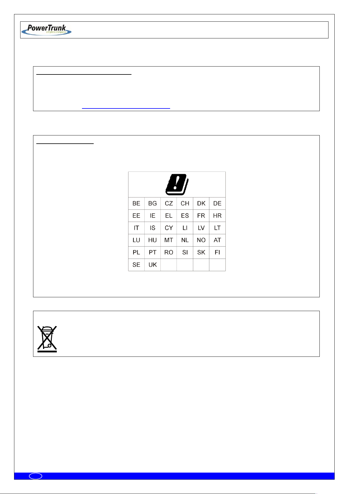
USE RESTRICTIONS
This radio equipment is subject to restrictions on putting into service or to requirements for authorization of
use in the following countries:
This equipment can be used in all Member States of the European Union once the corresponding
administrative license is obtained.
WASTE MANAGEMENT
The symbol means that the product must be taken to separate collection at the product end-of
life. Do not dispose of these products as unsorted municipal waste.

TETRA MBS UNIT. INSTALLATION GUIDE
F067646PT_2801
Page 3 of 62
en
PowerTrunk Inc. is the subsidiary of Teltronic S.A.U. responsible for business development, distribution and customer support for
Teltronic’s Land Mobile Radio products in North America. The company is headquartered in New Jersey. Teltronic S.A.U. distributes the
same products for Land Mobile Radio under different trademarks and brand names in other regions of the world.
Disclaimer
Although every reasonable effort has been made to ensure the accuracy of the information contained herein and in any other referred
document, this should not be construed as a commitment on the part of Teltronic S.A.U. and/or PowerTrunk Inc., and the liability of
Teltronic S.A.U. and/or PowerTrunk Inc. for any errors and omissions shall be limited to the correction of such errors and omissions.
Teltronic S.A.U. and/or PowerTrunk Inc. welcomes any comment as a way to improve any delivered documentation.
The information contained herein has been prepared for the use of appropriately trained personnel, and it is intended for the purpose of
the agreement under which the information is submitted. Any party using or relying upon this information assumes full responsibility for
such use and in no event shall Teltronic S.A.U. and/or PowerTrunk Inc. be liable to anyone for special, collateral, incidental, or
consequential damages in connection with or arising out of the use of this information.
The information or statements given in these documents regarding the suitability, capacity or performance of the mentioned hardware or
software products cannot be considered binding but shall be defined in the agreement made between Teltronic S.A.U. and/or
PowerTrunk Inc. and the customer.
Teltronic S.A.U. and/or PowerTrunk Inc. reserves the right to revise these documents and to make changes to their content at any time,
without prior notification.
Copyright
No part of the information contained herein and the other referred documents may be copied, distributed or transmitted by any means to
any other party without prior written permission of Teltronic S.A.U. and/or PowerTrunk Inc. The distribution of this document may be also
covered by NDA (non-disclosure agreement) between Teltronic S.A.U. and/or PowerTrunk Inc. and the receiver.
Please also note that part of these contents even may be covered by patent rights.
This document, the referred documents and the described product are considered protected by copyright according to the applicable
laws.
PowerTrunk and the PowerTrunk logo are registered trademarks of Teltronic S.A.U.
Copyright © PowerTrunk Inc. All rights reserved

TETRA MBS UNIT. INSTALLATION GUIDE
F067646PT_2801
Page 4 of 62
en
TABLE OF CONTENTS
1. INTRODUCTION 5
2. UNPACKING AND CHECKING 6
3. PREVIOUS CONSIDERATIONS 7
4. INFORMATION ON SAFETY AND ELECTROMAGNETIC COMPATIBILITY 8
4.1 GENERAL CONSIDERATIONS ABOUT SAFETY .................................................................................. 8
4.2 OPERATION AND EXPOSURE TO RF ENERGY ................................................................................... 9
4.3 IMPORTANT SAFETY NOTES ABOUT THE ANTENNA ...................................................................... 10
4.4 ELECTROMAGNETIC COMPATIBILITY REGULATORY INFORMATION (FCC AND ISED) ............. 11
4.5 UL / SAFETY CERTIFICATIONS ........................................................................................................... 12
4.6 EMC, SAFETY AND RF EXPOSURE STANDARDS ............................................................................. 12
4.7 MECHANICAL AND ENVIRONMENTAL STANDARDS ....................................................................... 13
4.7.1 STANDARDS CENELEC ...................................................................................................................................... 13
4.7.2 STANDARDS MIL-STD 810G ............................................................................................................................... 14
5. EQUIPMENT DESCRIPTION 15
5.1 VIEW ....................................................................................................................................................... 15
5.2 CONNECTORS ...................................................................................................................................... 16
5.3 VISUAL INDICATORS ........................................................................................................................... 18
5.4 DIMENSIONS ......................................................................................................................................... 19
6. INSTALLATION GUIDE 20
6.1 NECESSARY EQUIPMENT ................................................................................................................... 21
6.2 BASIC PRE-CONFIGURATION ............................................................................................................. 23
6.3 INSTALLATION ..................................................................................................................................... 24
6.3.1 MAST/POLE INSTALLATION ............................................................................................................................... 26
6.3.1.1 MAST/POLE SELECTION 26
6.3.1.2 MAST/POLE MOUNTING INSTRUCTIONS 28
6.3.2 WALL INSTALLATION .......................................................................................................................................... 31
6.3.3 PBS ACCESSORY INSTALLATION ..................................................................................................................... 34
6.3.3.1 WORKING POSITIONS 37
6.3.4 ANTI-VANDAL KIT INSTALLATION ...................................................................................................................... 39
6.3.5 REQUIREMENTS TO CONSIDER DURING THE ANTENNA INSTALLATION ..................................................... 40
6.3.6 CONNECTIONS ................................................................................................................................................... 42
6.3.6.1 SUPPORTED CONFIGURATIONS 43
6.3.6.2 CONNECTION OF THE EXTERNAL POWER SUPPLY 53
6.3.6.3 ANTENNA CONNECTION 56
6.3.6.4 EXTERNAL ETHERNET CONNECTION 57
6.3.7 CONNECTING / DISCONNECTING THE MBS AC MAINS SUPPLY .................................................................... 58
6.3.8 CONNECTING / DISCONNECTING THE MBS FROM THE DC SUPPLY ............................................................. 59
7. START UP/CONFIGURATION/VERIFICATION 60
8. INCIDENTS 61
8.1 INTERFERENCE AT MBS UNIT ............................................................................................................ 61
8.2 OVER VOLTAGE PROTECTION ........................................................................................................... 62
TETRA MBS UNIT. INSTALLATION GUIDE
F067646PT_2801
Page 5 of 62
en
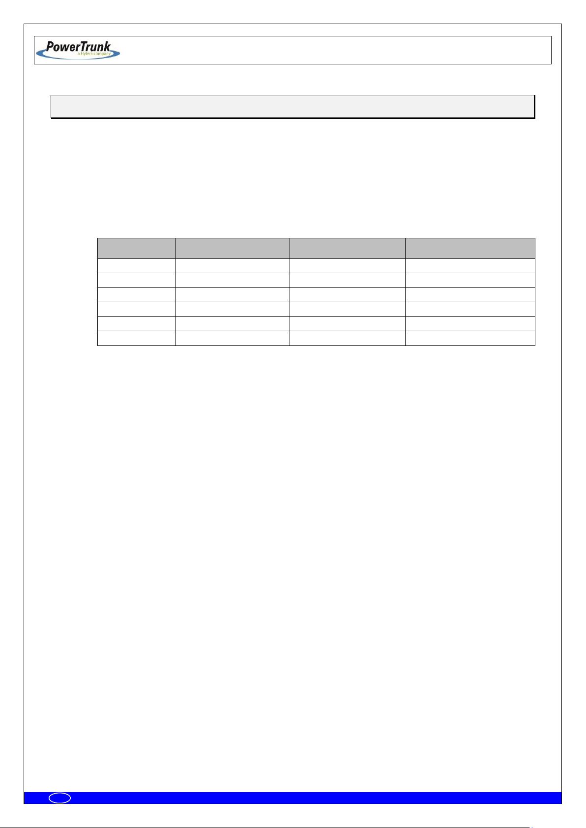
MBS Unit:
Frequency band:
Nominal transmitter
output power:
Maximum transmitter
output power:
D148H01PT
350-370 MHz
10 W
12.6 W
D148P01PT
380-400 MHz
10 W
12.6 W
D148701PT
409-430 MHz
10 W
12.6 W
D148101PT
425-470 MHz
10 W
12.6 W
D148K01PT
763-806 MHz
10 W
12.6 W
D148N01PT
806-870 MHz
10 W
12.6 W
1. INTRODUCTION
The MBS Units are the outdoor modules that make up a Mast Mounted Base Station (MBS). They
are independent units that can be interconnected with each other to increase the base station capacity. A
MBS consists of a maximum of two MBS Units.
The following table displays all the MBS Unit available models, together with their respective
frequency band and maximum RF transmitted power.
This manual is common to all the equipment models, including all their options and accessories.
The proper operation of any electronic device depends on its correct use. Therefore, it is
recommended to follow the instructions showed in this manual.
.

TETRA MBS UNIT. INSTALLATION GUIDE
F067646PT_2801
Page 6 of 62
en
2. UNPACKING AND CHECKING
The equipment is supplied with all the necessary materials for the installation, either on a mast, on a
wall or over the PBS Accessory:
MBS Unit includes the followings items
One power connector.
One Ethernet connector
RF super-flexible wire N-Male – N-Male.
Brackets for the installation.
Besides, in some types of installation, as detailed below, it is necessary an additional material that is
NOT supplied with the equipment.
IMPORTANT: If any of the necessary elements to carry out the installation process described in this
guide is missing or damaged, please contact your supplier.
TETRA MBS UNIT. INSTALLATION GUIDE
F067646PT_2801
Page 7 of 62
en
3. PREVIOUS CONSIDERATIONS
This manual contains information about instructions for installation, maintenance and use. Read the
following pages before using this equipment.
It is not advisable to switch on the equipment without having previously connected the antenna
otherwise irreparable damage could be. It is important to use an antenna adjusted to the work frequency.
TETRA MBS UNIT. INSTALLATION GUIDE
F067646PT_2801
Page 8 of 62
en
4. INFORMATION ON SAFETY AND ELECTROMAGNETIC COMPATIBILITY
4.1 GENERAL CONSIDERATIONS ABOUT SAFETY
PLEASE READ THESE INSTRUCTIONS CAREFULLY FOR IMPORTANT INFORMATION ABOUT
SAFELY OPERATING THIS PRODUCT
Most electronic equipment are susceptible to electromagnetic interference if they are not duly
protected. If the MBS Unit is placed near unprotected electronic devices, they may malfunction.
Only cables that fulfil the characteristics specified in this document must be used. Communication
cables must be shielded and earthed at both ends.
Take care when handling the MBS Unit. It has edges, which may cut if handled incorrectly.
Do not attempt to dismantle this product. Servicing and repairs to this product must be performed by
trained service technicians at PowerTrunk approved service centres.
PowerTrunk has not approved any changes or modifications to this device by the user. Any changes
or modifications could void the user’s authority to operate the equipment.
Only fit an approved accessory. If a non-approved accessory is fitted, it may compromise the product
safety ratings and may void any product warranty.
Maintenance and repair of this device must be carried out by qualified personnel only.
TETRA MBS UNIT. INSTALLATION GUIDE
F067646PT_2801
Page 9 of 62
en
4.2 OPERATION AND EXPOSURE TO RF ENERGY
It is the responsibility of the person operating the product to ensure that it is operated safely at all
times, and that local laws and regulations governing the usage of Radio Frequency (RF) wireless devices are
observed. Obey all signs and instructions relating to the usage to RF wireless devices.
PowerTrunk designs and manufactures products to meet strict guidelines and international standards
relating to Radio Frequency (RF) energy and the potential health risks associated with using RF wireless
devices. If you have any concerns relating to long term health risks associated with using RF wireless
devices, you should obtain advice from your employer.
FCC and ISED radiation exposure statement
This radio is intended for use in occupational/controlled applications where users have been made
aware of the potential risks for exposure and can exercise control over their exposure. This product is not
authorised for general population, consumer or similar use. This transmitter must not be co-located or
operated in conjunction with any other antenna or transmitter.
This equipment complies with FCC and ISED radiation exposure limits set forth for an uncontrolled
environment. The antenna should be installed and operated with minimum distance of 2 metres (2.19 yards)
between the radiator and your body. This transmitter must not be co-located or operating in conjunction with
any other antenna or transmitter.
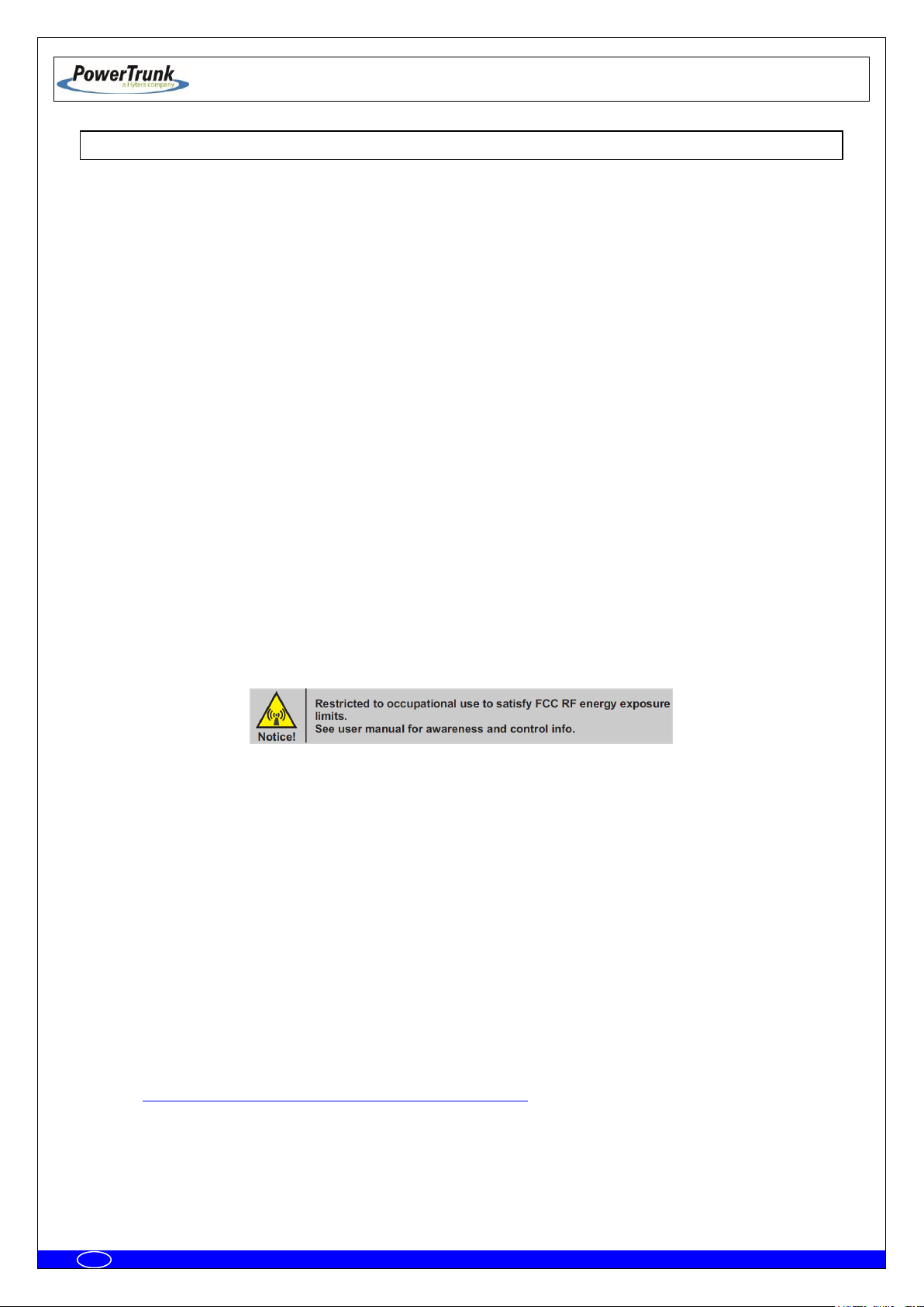
FCC compliance labelling on RF Exposure
The following compliance product labelling can be found in a conspicuous location of the MBS Unit
radio for North America market:
FCC notice on operating the device
The device may contain functions that are not operational in U.S Territories except as noted in the
certification filing. Devices may be restricted in frequency by the FCC TCB Grant. Please refer to it for
allowed frequency ranges. The TCB Grant may have extended frequencies as noted in the certification filing
and Section 2.927(b) may apply to the authorisation. The device complies with 47 CFR Part 90.203 (e), in
that the operator cannot directly program the transmit frequencies using the normal accessible external
controls. All instructions detailed in this manual must be followed in order to ensure compliance with RF
exposure limits.
Failure to observe these restrictions may result in exceeding the FCC RF exposure limits.
ISED Canada information on RF Exposure
The Government of Canada provides further information about RF Exposure by means of official
publications that are available on the following website:
http://www.ic.gc.ca/eic/site/smt-gst.nsf/eng/sf01904.html
TETRA MBS UNIT. INSTALLATION GUIDE
F067646PT_2801
Page 10 of 62
en
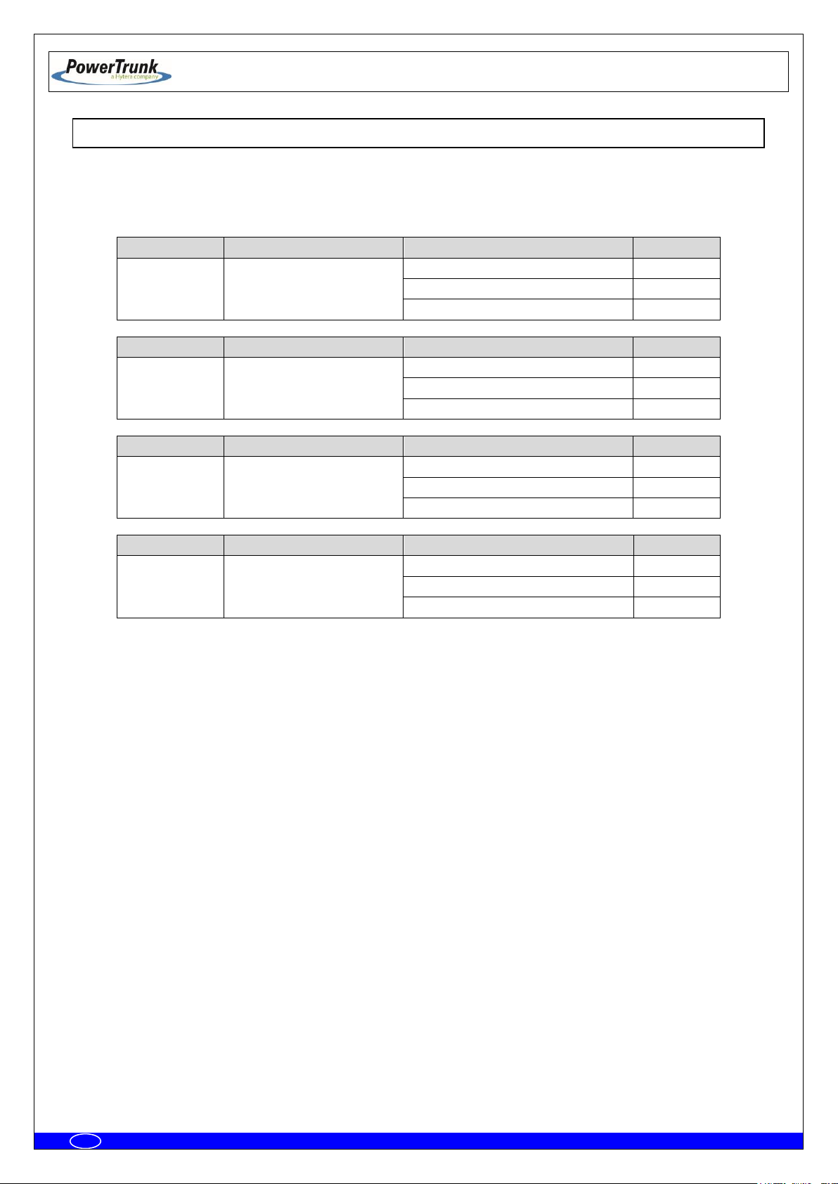
MODEL
CERTIFICATION NUMBER
TYPE OF ANTENNA
MAX.GAIN
MBS Unit –7
(409-430 MHz)
FCC ID: WT7PTRNKTMBS410
IC: 8624A-PTMBS410
Vertically polarised panel antenna
11.0 dBi
Cross-polarised panel antenna
15.0 dBi
Vertically polarised collinear antenna
11.15 dBi
MODEL
CERTIFICATION NUMBER
TYPE OF ANTENNA
MAX.GAIN
MBS Unit –1
(425-470 MHz)
FCC ID: WT7PTMBS450B
IC: 8624A-PTMBS450B
Vertically polarised panel antenna
11.0 dBi
Cross-polarised panel antenna
15.0 dBi
Vertically polarised collinear antenna
11.15 dBi
MODEL
CERTIFICATION NUMBER
TYPE OF ANTENNA
MAX.GAIN
MBS Unit –K
(763-806 MHz)
FCC ID: WT7PTMBS760B
IC: 8624A-PTMBS760B
Vertically polarised panel antenna
16.5 dBi
Cross-polarised panel antenna
18.0 dBi
Vertically polarised collinear antenna
11.15 dBi
MODEL
CERTIFICATION NUMBER
TYPE OF ANTENNA
MAX.GAIN
MBS Unit –N
(806-870 MHz)
FCC ID: WT7PTMBS800B
IC: 8624A-PTMBS800B
Vertically polarised panel antenna
16.5 dBi
Cross-polarised panel antenna
18.0 dBi
Vertically polarised collinear antenna
11.15 dBi
4.3 IMPORTANT SAFETY NOTES ABOUT THE ANTENNA
This radio has been approved by FCC and ISED to operate with the antenna types listed below with
the maximum permissible gain indicated. Antenna types not included in this list, having a gain greater than
the maximum gain indicated for that type, are strictly prohibited for use with this device.
Only use PowerTrunk approved antennas with this product. The use of non-approved antennas may
damage the product, will result in the non-compliance with regulatory requirements, will compromise the
product safety ratings, will reduce the length of operating time and will invalidate the product warranty.
Once the antenna has been installed, follow the guidelines for exposure of the human body to high
and low frequency electromagnetic fields. Follow the supplier’s / manufacturer’s instructions.
NEVER use your device without an antenna attached. Transmitting without an antenna may damage
your device
NEVER touch the antenna when your device is transmitting. This may cause a minor burn to the skin
and may affect the operational range of the antenna.
NEVER use your device if the antenna shows signs of damage.

TETRA MBS UNIT. INSTALLATION GUIDE
F067646PT_2801
Page 11 of 62
en
4.4 ELECTROMAGNETIC COMPATIBILITY REGULATORY INFORMATION (FCC AND ISED)
These devices generate, use and radiate RF energy and, if not installed and used in accordance with
the instruction manual, may cause harmful interference to radio communications.
FCC interference statement and compliance labelling
This device complies with Part 15 of the FCC Rules. Operation is subject to the following two
conditions: (1) this device may not cause interference, and (2) this device must accept any interference,
including interference that may cause undesired operation of the device.
A label with the text above can be found in a conspicuous location of the MBS Unit for North America
market.
FCC Class B digital device notice
This equipment has been tested and found to comply with the limits for a Class B digital device, pursuant
to part 15 of the FCC Rules. These limits are designed to provide reasonable protection against harmful
interference in a residential installation. This equipment generates, uses and can radiate radio frequency
energy and, if not installed and used in accordance with the instructions, may cause harmful interference to
radio communications. However, there is no guarantee that interference will not occur in a particular
installation. If this equipment does cause harmful interference to radio or television reception, which can be
determined by turning the equipment off and on, the user is encouraged to try to correct the interference by
one or more of the following measures:
- Reorient or relocate the receiving antenna.
- Increase the separation between the equipment and receiver.
- Connect the equipment into an outlet on a circuit different from that to which the receiver is
connected.
- Consult the dealer or an experienced radio/TV technician for help.
ISED Canada ICES-003 compliance labelling
This Class B digital apparatus has been fully tested and found to comply with the Canadian ISED
(Innovation, Science and Economic Development) standard ICES-003. A label with the text below can be
found in a prominent location of the radio for North America market:
CAN ICES-3 (B) / NMB-3 (B)
TETRA MBS UNIT. INSTALLATION GUIDE
F067646PT_2801
Page 12 of 62
en
ETSI EN 300 394-1
Terrestrial Trunked Radio (TETRA);Conformance testing
specification; Part 1: Radio
ETSI EN 301 489-1
Electromagnetic Compatibility and Radio spectrum Matters
(ERM); ElectroMagnetic Compatibility (EMC) standard for
radio equipment and services; Part 1: Common technical
requirements
ETSI EN 301 489-5
ElectroMagnetic Compatibility (EMC) standard for radio
equipment and services; Part 5: Specific conditions for
Private land Mobile Radio (PMR) and ancillary equipment
(speech and non-speech) and Terrestrial Trunked Radio
(TETRA)
EN 50121-4
Railway applications - Electromagnetic compatibility - Part
4: Emission and immunity of the signaling and
telecommunications apparatus
EN 60950-1 / IEC 60950-1 / UL 60950-1 / CSA
60950-1
Information technology equipment - Safety -- Part 1:
General requirements
EN 60950-22 / IEC 60950-22 / UL 60950-22 /
CSA 60950-22
Information technology equipment - Safety -- Part 22:
Equipment to be installed outdoors
EN 50383
Basic standard for the calculation and measurement of
electromagnetic field strength and SAR related to human
exposure from radio base stations and fixed terminal
stations for wireless telecommunication systems (110 MHz
- 40 GHz)
EN 50385
Product standard to demonstrate the compliance of radio
base stations and fixed terminal stations for wireless
telecommunication systems with the basic restrictions or
the reference levels related to human exposure to radio
frequency electromagnetic fields (110 MHz - 40 GHz) General public
4.5 UL / SAFETY CERTIFICATIONS
The MBS Unit is UL certified, and complies with the requirements for electronic
devices to minimise risks such as fire, electric shocks or injuries to the operator that may
be caused in operation. File number is the following: E318948.
MBS Unit complies with the standard UL 60950-1 and UL 60950-22, including the
National Differences for United States, Canada and CENELEC (Europe), and it has CB
Test Certificate.
4.6 EMC, SAFETY AND RF EXPOSURE STANDARDS
The equipment has been designed according to the following standards:
Most of these standards ensure the essential requirements set out in Article 3 of Directive 2014/53/UE.

TETRA MBS UNIT. INSTALLATION GUIDE
F067646PT_2801
Page 13 of 62
en
EN 60068-2-1
* No Functional. - 104 ºF. Duration: 72 h
* Functional: - 86 ºF. Duration: 16 h.
Environmental testing -- Part 2-1: Tests - Test A: Cold
EN 60068-2-2
* No Functional. + 185 ºF. Duration: 72 h
* Functional: + 140 ºF. Duration: 16 h.
Environmental testing -- Part 2-2: Tests - Test B: Dry heat
EN 60068-2-78
* Functional + 140 ºF 93%. Duration 21 days.
Environmental testing -- Part 2-78: Tests - Test Cab: Damp
heat, steady state
EN 60068-2-30
* Functional: 6 cycles 24 hours:
• 12 hours. Temperature: + 140 ºF. Relative
humidity: 95% ± 5%
• 12 hour: Temperature + 77 ºF. Relative
humidity: 98% ± 5%
Environmental testing -- Part 2-30: Tests - Test Db: Damp
heat, cyclic (12 h + 12 h cycle)
EN 60068-2-11
No functional: 672 hours. + 95 ºF +/- 35.6 ºF. 5%
ClNa
Environmental testing -- Part 2: Tests - Test Ka: Salt mist
EN 60529
* No functional. IP66
Degrees of protection provided by enclosures (IP Code).
EN 60068-2-9
* No functional.
• Proc. B: 20 hours of solar radiation and 4
hours of darkness
• Temperature: +104 ºF
• Humidity: 65%
• Duration: 10 days
Environmental testing -- Part 2: Tests - Guidance for solar
radiation testing.
EN 60068-2-64
* No functional:
• Duration: 30 minutes by axe
• 5-20 Hz. ASD: 0.01 g2/Hz.
• 20-200 Hz. ASD; - 3dB/oct
Environmental testing -- Part 2-64: Tests - Test Fh:
Vibration, broadband random and guidance.
EN 60068-2-6
* No functional:
• Duration: 5 sweep by axe
• 5-9 Hz. Displacement 0.05 in.
• 9-200 Hz. Acceleration 0.41 g
Environmental testing -- Part 2-6: Tests - Test Fc: Vibration
(sinusoidal).
4.7 MECHANICAL AND ENVIRONMENTAL STANDARDS
The equipment complies with the following standards:
4.7.1 STANDARDS CENELEC
TETRA MBS UNIT. INSTALLATION GUIDE
F067646PT_2801
Page 14 of 62
en
UNE-EN 60598
* Vibration type: Sine swept
* Frequency range: From 10 to 55 Hz
* Amplitude (peak):
• 10 Hz Amplitude (peak): 0.06 in
• 38 Hz Amplitude (peak): 2.04 g
• 55 Hz Amplitude (peak): 2.04 g
* Number of axes: 3 axes
* Swept ratio: 1 Oct./min.
* Duration: 30 min./axis
Vibration: simulation of the fixing between MBS unit and
mast.
Eurocode UNE-EN 1991-1-4
* Wind speed: 124.27 mi /h (60.75 yd /s) (Safety
factor 1.5)
* Height in post: 21.87 yd
Protection for avoiding damages either in the enclosure
and the fixing parts, due to meteo effects such as strong
gusts of wind.
MIL-STD-810G METHOD 502.5 procedure I, (C2):
- 104 ºF. Duration: 72 h
Cold (Storage and transportation).
MIL-STD-810G METHOD 502.5 procedure I, (C1):
- 86 ºF. Duration: 16 h
Cold (Operation).
MIL-STD-810G METHOD 501.5 procedure I (A1): +
185 ºF. Duration: 72 h
Dry Heat (Storage and transportation).
MIL-STD-810G METHOD 501.5 procedure I (A2): +
140 ºF. Duration: 16 h
Dry Heat (Operation).
MIL-STD-810G - Method 507.5, procedure II
(Aggravated): (10 cycles, 24 hours) 86 ºF - 140 ºF
at 95%rH.
Humidity.
MIL-STD-810G - Method 509.5
672 hours. + 95 ºF +/- 35.6 ºF. 5% ClNa.
Salt Fog.
MIL-STD-810G - Method 505.5:
- Proc. B: 20 hours of solar radiation and 4
hours of darkness
- Temperature: +104 ºF
- Humidity: 65%
- Duration: 10 days
Solar Radiation (Sunshine).
MIL_STD-810G 514.6, Test procedure I, Category
4, table C-VI C3 (Figure 514,6 C-3)
Vibration.
MIL-STD-810G 516.6 Test procedure I and III, 0.71
oz 11 ms, half sinus
Shock.
4.7.2 STANDARDS MIL-STD 810G
TETRA MBS UNIT. INSTALLATION GUIDE
F067646PT_2801
Page 15 of 62
en
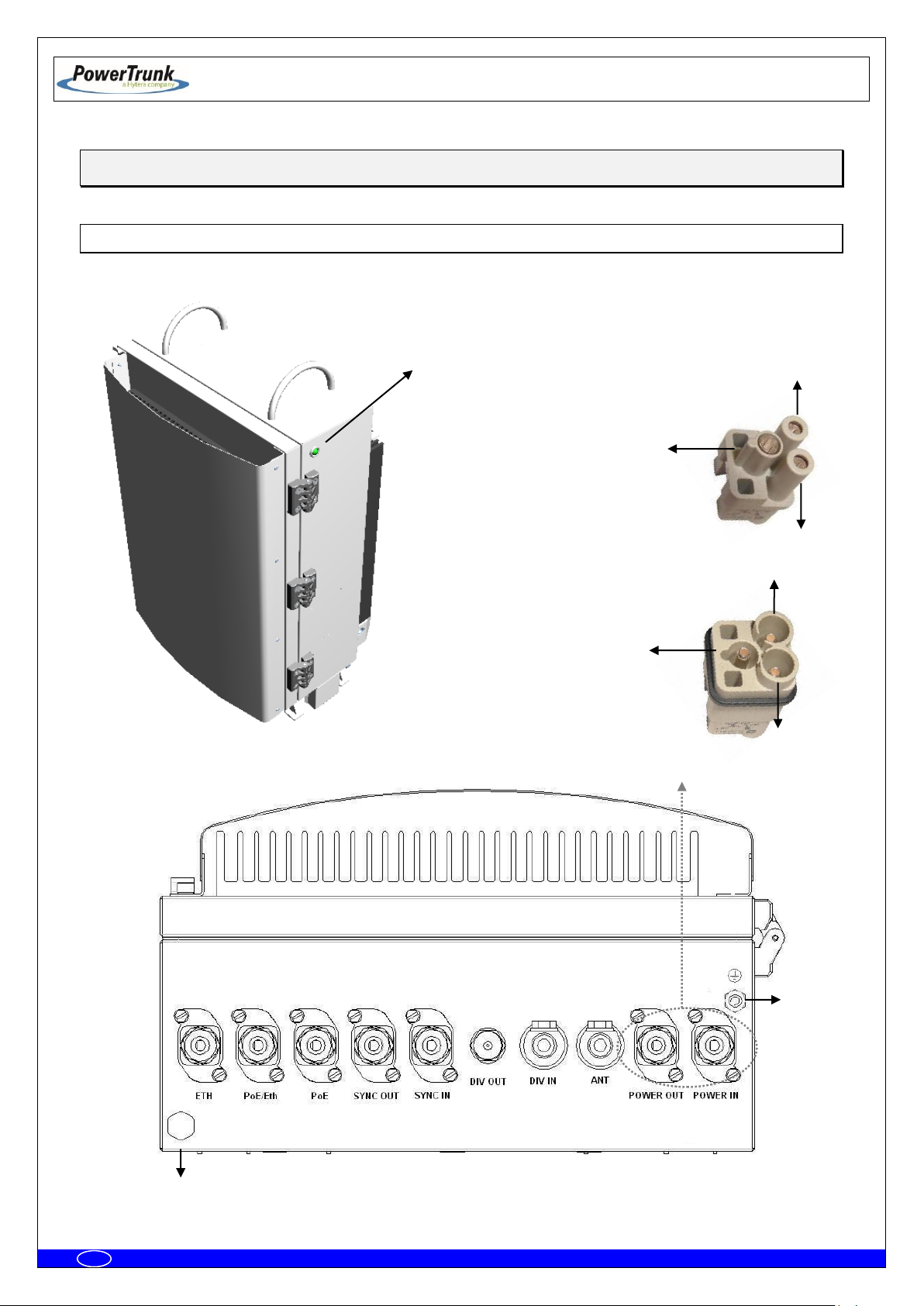
2 1 3
Male panel connector
1
2
Female cable connector
3
State
LED
5
4
5. EQUIPMENT DESCRIPTION
5.1 VIEW

TETRA MBS UNIT. INSTALLATION GUIDE
F067646PT_2801
Page 16 of 62
en
5.2 CONNECTORS
1.- Terminal with the following meaning depending on the MBS Unit Power option:
- AC MBS Units: Neutral contact (N).
- DC MBS Units: Negative contact (-).
2.- Terminal with the following meaning depending on the MBS Unit Power option:
- AC MBS Units: Line contact (L).
- DC MBS Units: Positive contact (+).
3.- Power supply Earth contact.
4.- Pressure equalizer.
5.- Chassis Earth contact.
ETH: Connector that allows Ethernet connection between MBS Units. It also can be used as
Maintenance Ethernet connector.
PoE/ETH: Power Over Ethernet (IEEE 802.3af) connector. It provides power supply (48 VDC) and
Ethernet connection to a PoE radio link. It can be used as Maintenance Ethernet connector if there is
not radio link (Poe) connected. If the MBS Unit has the SNI IP option this connector is Layer 3.
PoE: Power Over Ethernet (IEEE 802.3af) connector. It provides power supply (48 VDC) and
Ethernet connection to a PoE radio link. If the MBS Unit has the SNI IP option this connector is Layer
3.
SYNC OUT: Synchronism output connector. It provides synchronism to a second MBS Unit through
its SYNC_IN connector.
SYNC IN: Synchronism input connector.
DIV OUT: Output reception connector. It provides the receiver chain 2 to the next MBS Unit through
its DIV IN connector.
DIV IN: Reception antenna connector (receiver chain 2). It is connected to an antenna or to a MBS
Unit DIV OUT connector (diversity 2).
ANT: Transmission/reception antenna power connector (receiver chain 1).
POWER OUT: Output power supply connector. It provides power supply to another MBS Unit with
the same Power Supply option.
POWER IN: Input power supply connector (VAC or VDC).
TETRA MBS UNIT. INSTALLATION GUIDE
F067646PT_2801
Page 17 of 62
en
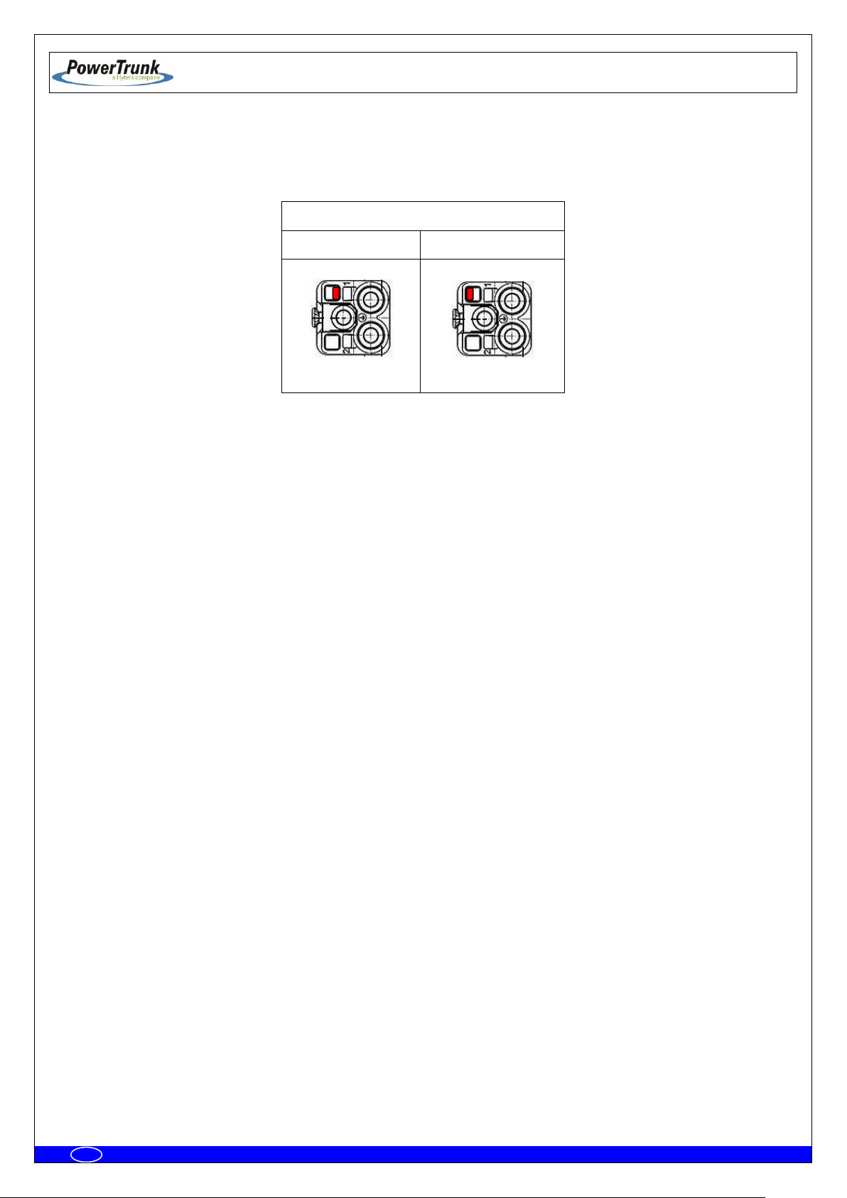
External view of power supply panel connector
AC Power Supply
DC Power Supply
Note: POWER_IN and POWER_OUT connectors have a coding key to avoid wrong connections; on the
following table is showed the location of this coding key depending on the MBS Unit power supply option.
Note: The amount of power delivered by both PoE and PoE/ETH connectors to the radio links can not
exceed 35 W in total.
TETRA MBS UNIT. INSTALLATION GUIDE
F067646PT_2801
Page 18 of 62
en
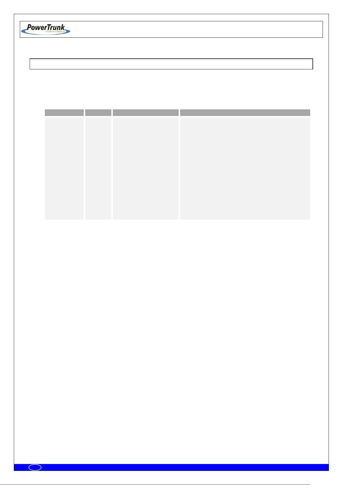
LED
TYPE
NORMAL STATE
FUNCTIÓN
STATE
Tricolor
Green ON / Orange ON
Green On: MBS Unit is operating and
transmitting.
Green flashing: MBS Unit initializing
Red On: There is no link with CNC and no
control from any LSC.
Red flashing: When MBS Unit is controlled by
the CNC, showing any kind of alarm other than
the communication one is NOT OK.
Orange On: MBS Unit is operating and
transmitting in fallback mode.
Orange flashing: When MBS Unit is in
fallback mode, showing any kind of alarm other
than the communication one is NOT OK.
OFF: The equipment is either without power
source or is damaged.
5.3 VISUAL INDICATORS
A MBS Unit has a LED indicator that, depending on its state, will indicate the function of the MBS Unit
The LEDs show the MBS Unit state:
TETRA MBS UNIT. INSTALLATION GUIDE
F067646PT_2801
Page 19 of 62
en
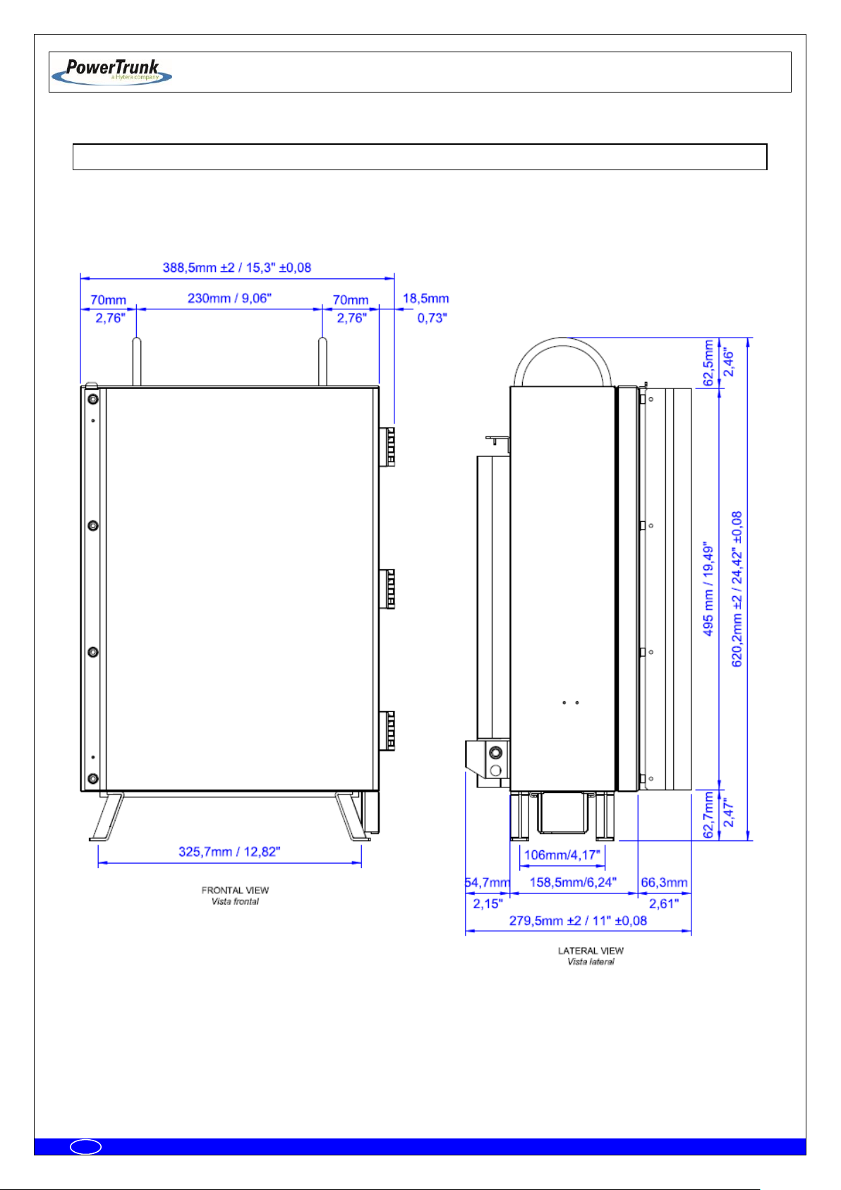
5.4 DIMENSIONS
 Loading...