


User Guide
HTT-500-2 hand-portable radio

Original Instructions: ENGLISH
Document Number: PD-UG-0010
Issue 1.2
Copyright
© PowerTrunk, Inc. 2002–2016. All rights reserved.
No part of the information contained herein and the other referred documents may be copied, distributed or transmitted by
any means to any other party without prior written permission of Teltronic S.A.U. and/or PowerTrunk Inc. The distribution
of this document may be also covered by NDA (non-disclosure agreement) between Teltronic S.A.U. and/or PowerTrunk
Inc. and the receiver.
Please also note that part of these contents even may be covered by patent rights.
This document, the referred documents and the described product are considered protected by copyright according to the
applicable laws.
PowerTrunk and the PowerTrunk logo are registered trademarks of Teltronic S.A.U.
Disclaimer
Although every reasonable effort has been made to ensure the accuracy of the information contained herein and any other
referred document, this should not be construed as a commitment on the part of Teltronic S.A.U. and/or PowerTrunk Inc.,
and the liability of Teltronic S.A.U. and/or PowerTrunk Inc. for any errors and omissions shall be limited to the correction
of such errors and omissions. Teltronic S.A.U. and/or PowerTrunk Inc. welcomes any comment as a way to improve any
delivered documentation. The information contained herein has been prepared for the use of appropriately trained
personnel, and it is intended for the purpose of the agreement under which the information is submitted. Any party using or
relying upon this information assumes full responsibility for such use and in no event shall Teltronic S.A.U. and/or
PowerTrunk Inc. be liable to anyone for especial, collateral, incidental, or consequential damages in connection with or
arising out of the use of this information. The information or statements given in these d ocuments regarding the suitability,
capacity or performance of the mentioned hardware or software products cannot be considered binding but shall be d efined
in the agreement made between Teltronic S.A.U. and/or PowerTrunk Inc. and the customer. Teltronic S.A.U. and/or
PowerTrunk Inc. reserves the right to revise these documents and to make changes to its content at any time, without prior
notification.
Software license agreement
NOTICE: CAREFULLY READ THE LEGAL AGREEMENT CORRESPONDING TO THE LICENSE YOU PURCHASED,
WHICH SETS FORTH THE GENERAL TERMS AND CONDITIONS FOR THE USE OF THE LICENSED SOFTWARE.
Contact Details
PowerTrunk, Inc.
66 York Street Jersey City
NJ 07302
U.S.A.
T: +1 201 630 4520
F: +1 201 630 4522
ii
HTT-500-2 – 12/2016

CONTENTS
General information 1
Safety Information 1
Regulatory 2
How to use this document 4
Your radio at a glance 6
Battery 8
Charging the battery 9
Charging a 'flat' battery 10
Fitting the battery 10
Removing the battery 11
Using Sepura approved batteries 11
Controls & indicators 13
Navi-knob 13
Navigation Keys 13
Soft keys 14
Context keys 15
Status icons 16
LED indicators 21
Emergency button 22
Getting Started 23
Fitting a microSD card 23
Fitting a Smart card 24
Antenna 25
Power on 26
Power off 26
Locking and unlocking the keypad 27
Home screen 28
Shortcut Bar 29
Notifications 30
User Guide
iii

Menu 31
SmartMenus 33
Help 34
Emergency operation 36
Making an Alarm call 37
Receiving an Alarm call 37
Clearing an Alarm call 38
Power on Alarm call 38
Sound 40
Adjusting the volume 40
Loudspeaker on/off 40
Whisper mode 40
Audible tone alerts 41
Vibration alerts (Haptics) 42
Personalising your radio 43
Invert the display 43
Adjusting the backlight 43
Day/Night mode 44
Adjusting text and icon size 45
Setting the display language 46
Menu style 46
Time and Date 48
Talkgroups and folders 49
Special folders 50
Typical folder arrangement 52
Talkgroup Selection Mode 53
Folder Selection Mode 58
Contacts 65
Searching and filtering contacts 66
View contact details 67
iv
HTT-500-2 – 12/2016

Creating contacts 67
Editing contacts 68
Delete all contacts 69
Calls 70
Call types 70
Call History 72
Group calls 73
Individual calls 74
Broadcast calls 76
Quick Calls 78
Smart Calls 78
Modifying your call setup 79
Text entry 81
Cursor movement 81
Character sets 82
Messages 84
Message Inbox 84
Opening messages 86
View message details 86
Reply to a message 87
Saved messages 87
Picture messages 92
Paging alerts 92
Networks 94
Authentication 94
Change Network 95
Transmit Inhibit 95
Fallback Mode 96
Operating Modes 98
DMO Mode 99
User Guide
v

Repeater Mode 101
P25 Mutual Aid mode 105
Callout alerts 110
Responding to Callouts 111
Callout display 116
Group calls to Callout group 118
Information Phase 118
Features 121
Privacy Screen 121
View images 121
Connector Protector 122
User profiles 123
Man Down 125
Lone Worker 127
WAP 128
Using WAP 128
Browser menu 129
Navigation menu 130
Settings 130
History menu 132
Using bookmarks 133
Call handling 134
GPS 137
GPS position 137
GPS direction 138
GPS reporting options 139
Bluetooth® 140
Bluetooth® on/off 141
Audio devices 141
Data devices 143
vi
HTT-500-2 – 12/2016

Modify connected devices 146
Security 147
PIN entry 147
Change PIN 148
Unlocking the radio after incorrect PIN entry 148
End-to-End Encryption 148
Zeroising 150
Asset management 151
Labelling 151
RFID tag 152
Customising your radio 153
Accessories 155
Belt clip 156
Klick fast stud 157
Fit an accessory 159
GLOSSARY 161
User Guide
vii

viii
HTT-500-2 – 12/2016

General information
This user guide describes the default operation and features of the HTT-500-2
radio. Your service provider or organisation may have customised your radio
to optimise its performance to suit your individual needs. There may be
differences between this guide and the way your product operates. Contact
your service provider or organisation for information about the customisation
of your radio.
Safety Information
Before using this product read the safety and regulatory information
contained in the Product Safety Guide (SPR-DOC-00170) supplied with your
radio. It is your responsibility to ensure that this product is operated safely at
all times, and that local laws governing the use of Radio Frequency (RF)
devices are observed.
PowerTrunk products are designed for use by mobile workforces, often
working alone, and are intended for use in occupational and controlled
conditions. It is recommended that you obtain training on how to operate this
product. Your personal safety could be at risk if you do not understand how
to operate this product correctly.
PowerTrunk products have been tested to meet strict guidelines for personal
safety and operational conditions. Do not operate this product in
environments that exceed those listed on the product technical data sheet.
Important safety notes about the antenna
Only use PowerTrunk approved antennas with this product. PowerTrunk
TETRA radios have been tested and certified for European, FCC and IC safety
and compliance regulations using the following antennas:
Model Antenna (part no.)
HTT-500-2 300-00498
User Guide
1
The use of non-approved antennas may damage the product, will result in
the non-compliance with regulatory requirements, compromise the product
safety ratings, reduce the length of operating time and will invalidate the
product warranty.
NEVER touch the antenna when your radio is transmitting, this may cause a
minor burn to the skin and may affect the operational range of the antenna.
DO NOT handle, hold or swing your radio by its antenna, this may damage
your radio and the antenna.
NEVER use your radio if the antenna shows signs for damage.
NEVER use your radio without an antenna attached, unless your radio is
being used with an external antenna (such as an RSM antenna).
Transmitting without an antenna may damage your radio.
Regulatory
Waste Electrical and Electronic Equipment disposal information
This symbol on the product or its packaging indicates that this product must
not be disposed of as household or commercial waste. Some countries have
set up collection and recycling systems for waste electrical and electronic
products. By ensuring that this product is disposed of correctly, you will help
prevent potentially negative consequences for the environment and human
health, and help conserve natural resources. Please dispose of your waste
product according to your national and local regulations. Contact your
service provider or PowerTrunk, Inc. for information about disposing of this
product in your region of the world
Federal Communication Commission (FCC) Regulations
PowerTrunk, Inc. TETRA radios generate, use and radiate RF energy and, if
not installed and used in accordance with the instruction manual, may cause
harmful interference to radio communications. Radios that comply with the
limits for a Class A digital device, pursuant of part 15 of the FCC rules, are
identified by an FCC certification ID label (located under the battery).
Operation is subject to the following two conditions: (1) This device may not
cause harmful interference, and (2) this device must accept any interference
2
HTT-500-2 – 12/2016

received, including interference that may cause undesired operation. These
limits are designed to provide reasonable protection against harmful
interference when the equipment is operated in a commercial environment.
Operation of this equipment in a residential area is likely to cause harmful
interference in which case the user will be required to correct the interference
at their own expense. Changes or modifications not expressly approved by
the party responsible for compliance could void the user's authority to
operate the equipment.
The device may contain functions that are not operational in U.S Territories
except as noted in the certification filing. The TCB Grant may have extended
frequencies as noted in the certification filing and Section 2.927(b) may apply
to the authorisation. The device complies with 47 CFR Part 90.203 (e), in that
the operator cannot directly program the transmit frequencies using the
normal accessible external controls. All instructions detailed in this manual
must be followed in order to ensure compliance with SAR and RF exposure
limits.
Failure to observe these restrictions may result in exceeding the FCC RF
exposure limits.
US and Canada Markets
PowerTrunk radios may be restricted in frequency by the relevant IC FCB or
FCC TCB Grant. Refer to the Grant for allowed frequency ranges.
PowerTrunk HTT-5000-2 hand-portable radios are approved Class A digital
apparatus that comply with Canadian ICES-003.
FCC radiation exposure statement
This radio is intended for use in occupational/controlled applications where
users have been made aware of the potential risks for exposure and can
exercise control over their exposure. This product is not authorised for
general population, consumer or similar use. This transmitter must not be colocated or operated in conjunction with any other antenna or transmitter.
IC RSS warning
The term “IC:” before the certification/registration number only signifies that
the Industry Canada technical specifications were met. Nominal antenna port
impedance is 50 Ω.
User Guide
3
IC radiation exposure statement
This radio is intended for use in occupational/controlled applications where
users have been made aware of the potential risks for exposure and can
exercise control over their exposure. This product is not authorised for
general population, consumer or similar use. This transmitter must not be colocated or operating in conjunction with any other antenna or transmitter.
Full details of RF exposure and compliance can be found at
http://www.ic.gc.ca.
Compliance product labelling
The following compliance product labelling apples to the HTT-500-2 handportable radio:
Product Compliance product labelling
HTT-500-2 CAN ICES-3 (A)/NMB-3(A)
This device complies with Part 15 of the FCC Rules.
HTT-500-2
HTT-500-2
Operation is subject to the condition that this device does not
cause harmful interference.
This radio is restricted to occupational use only to
satisfy FCC RF energy exposure limits. Read the
user guide for awareness and control information.
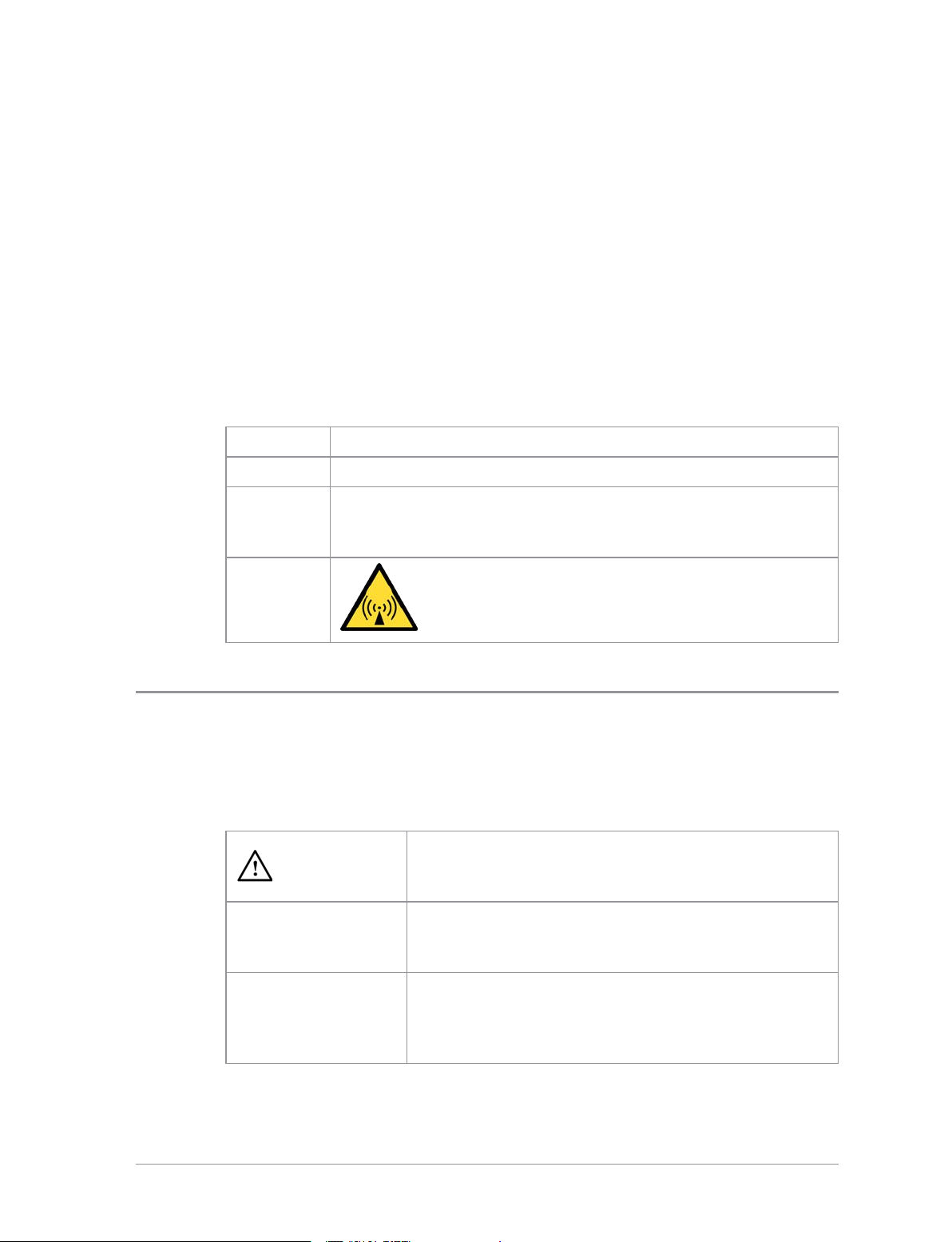
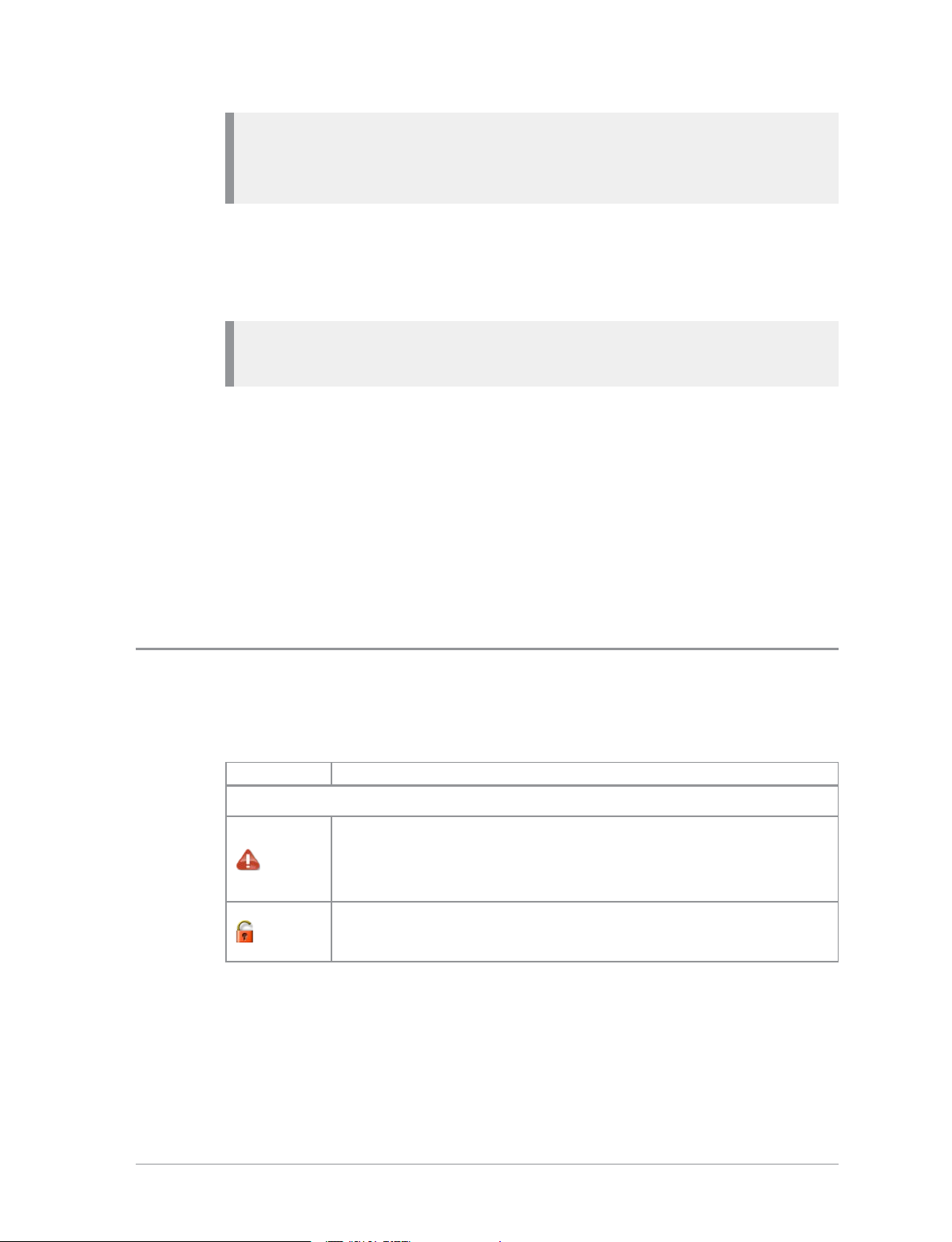
How to use this document
Icons and other visual cues are used throughout this document to help the
reader with important information. These icons and visual cues are described
below:
Indicates that this information is important and if
Warning:
Caution:
Note:
disregarded could result in an injury to yourself or
to others.
Indicates that this information is important and if
disregarded could result in serious damage to the
product or other devices or a minor injury.
Contains additional information that could be
exceptions to the general text. They may also
contain references to additional information in this
guide or other reading material.
4
HTT-500-2 – 12/2016

Tip:
Contains additional information that could help you
perform a task quicker by offering an alternative
method to that in the general text.
Bold typeface
Menu > Phone >
Contacts
Used to highlight parts of the radio, such as keys
and buttons, key presses and menu options.
Indicates navigation through the menu structure to
the desired option based on the default language
strings. Note: your radio may be customised to use
different language strings.
User Guide
5
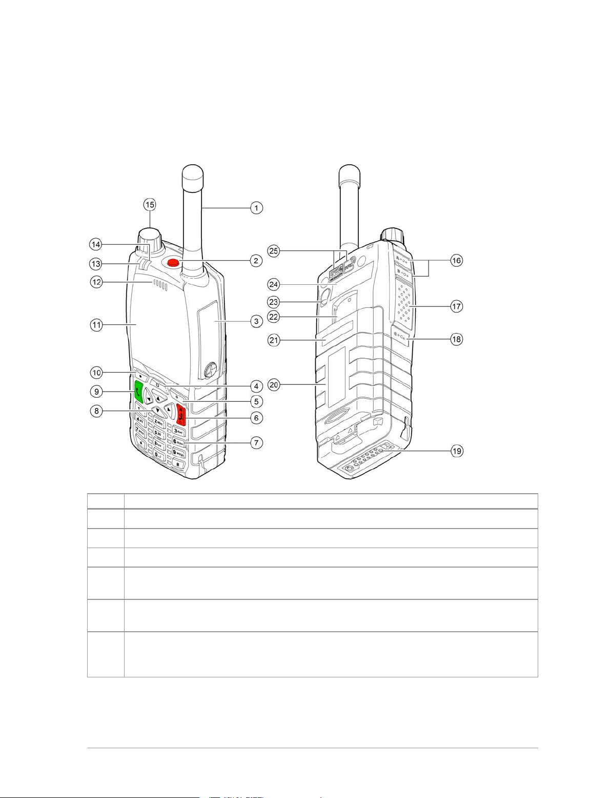
Your radio at a glance
Item Description
1 Antenna.
2 Emergency Button. Press and hold (2 seconds) to initiate an Alarm call.
3 Rugged Accessory Connector (sRAC). Provides connection for accessories.
4
5
6
6
Centre context key. Press to activate the feature or option that appears directly
above the key.
Right context key. Press to activate the feature or option that appears directly
above the key.
Cancel/Home key. Press and hold (2 seconds) to power on your radio. From
the Home screen, press and hold (4 seconds) to power off. Press and hold (2
seconds) to return to the Home screen from any other screen.
HTT-500-2 – 12/2016

Item Description
Alphanumeric keypad with backlight. Loudspeaker and microphone behind.
The loudspeaker is used during Group calls when an audio acccessory is not
7
connected and the radio is held in the hand. The microphone is used during
phone calls. Use the keypad to enter alphanumeric characters for text editing
and dialling. Keys 0–9, # and * are programmable soft keys.
8
Navigation keys. Press to scroll through lists and move the cursor when
writing text.
9 Select/Send key. Press to initiate a phone call.
10
Left context key. Press to activate the feature or option that appears directly
above the key.
11 Colour display with backlight.
Earpiece and microphone. Earpiece is active during phone calls when the
12
radio is held like a smart phone against the ear. Speak into the microphone
during Group calls when the radio is not attached to an audio accessory and
held in the hand.
13 Tri-colour LED (indicator). Indicates various operational states of the radio.
14
Blue LED (indicator). Indicates a missed event such as a call, Callout or
message. Also indicates Bluetooth® status.
15 Navi-knob. A continuously rotating knob used to adjust the speaker volume.
16 Side Button (A/B). Press to activate a programmed feature.
17
PTT (Press-to-talk) button. Press and hold to talk during a group call. Release
to listen to other radio users.
18 Side Button (C). Press to activate a programmed feature.
19
Digital Accessory Connector (sDAC). Used to charge the battery, program
the radio and attach accessories.
20 Battery
21 Battery label area for attaching an asset label (optional).
22
23
Attachment point for accessory used to connect a belt clip or other accessory
designed for securing the radio during use.
External Antenna Connector used with a car kit to attach an external antenna
to the radio.
24 Radio ID Label for attaching an asset label (optional).
25 RFID tag for monitoring and auditing purposes.
User Guide
7
Battery
For your safety, inspect the battery regularly for any signs of damage,
such as cracks or surface damage caused by an impact or the battery
being dropped. Fit a new battery if there are any signs of damage.
Warning: Risk to personal safety. PowerTrunk TETRA radios have
been tested and certified using Sepura approved batteries. The use of
non-approved batteries may damage the product, will result in noncompliance with regulatory requirements, compromise the product
safety ratings including SARS, reduce the length of operating time and
will invalidate the product warranty.
Checking the battery charge
Always check the amount of battery charge before lengthy periods of
operation. A fully charged battery should provide continuous operation for a
full shift, depending on a number of operational factors such as how the
radio is operated, the operating environment (temperature and network
signal strength) and the condition of the battery. When the radio is powered
on, the amount of charge remaining may be displayed as a percentage (%) on
the screen.
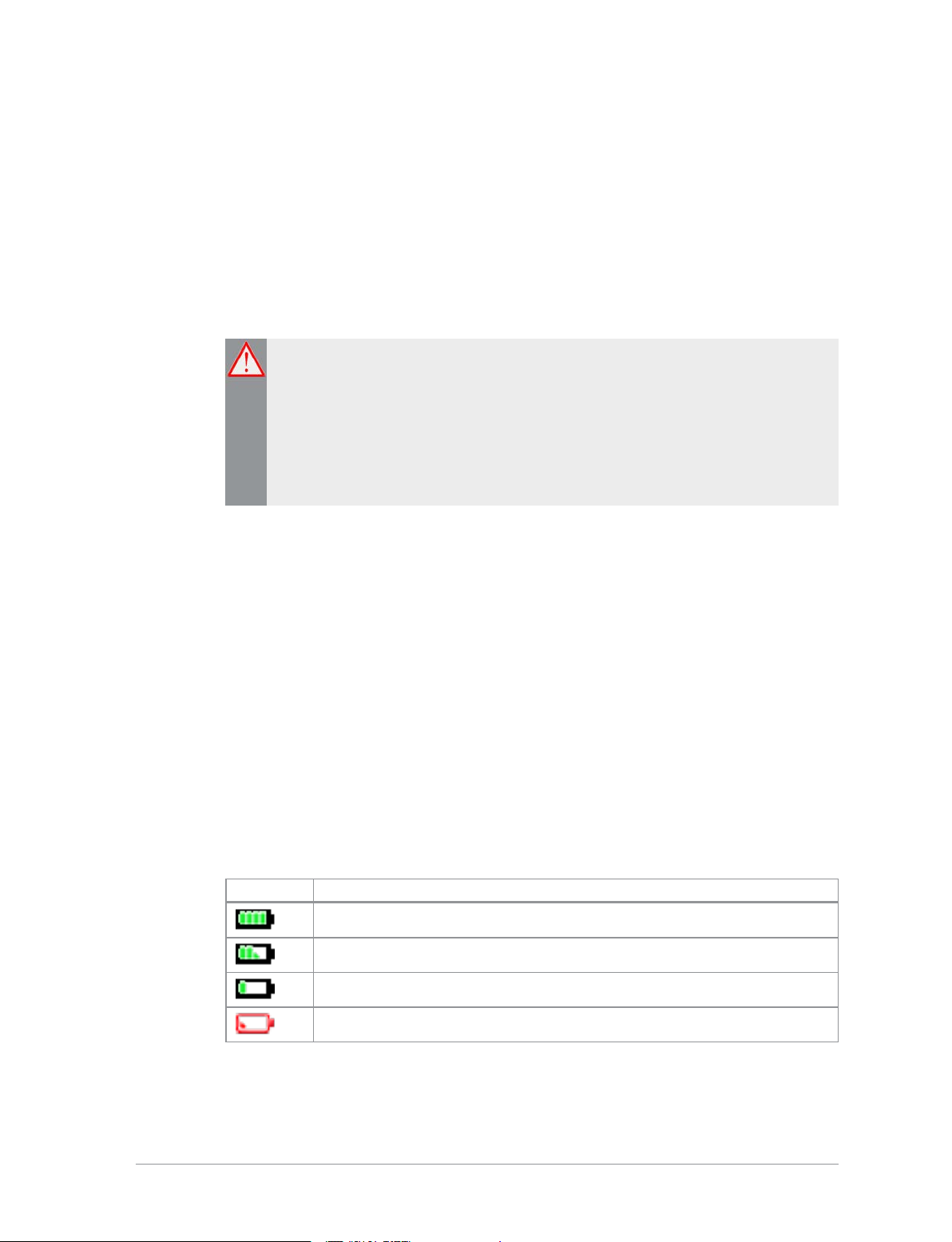
Battery charge indicators
A battery meter appears on the status line at the top of the radio display. The
meter consists of 4 bars comprising 8 segments that fill and empty
corresponding to the estimated amount of charge remaining.
Icon Description
Battery is fully charged.
Battery is 50% charge capacity.
Battery has >12% charge remaining.
Battery charge less than 12% charge remaining.
8
HTT-500-2 – 12/2016

Optimising battery life
A fully charged battery should last a full shift (approximately 12 hours) but
this depends on a number of operational factors, such as how the radio is
operated, the operating environment (temperature and network signal
strength) and the condition of the battery.
Try the following to help you optimise battery life on a daily basis:
Ensure that batteries are fully charged at the start of a shift.
Decrease the amount of time the backlight stays lit between key presses
(see Adjusting the backlight on page43).
Keep your speaker audio volume to a minimum (see Adjusting the volume
on page40).
Reduce the length of time the radio is transmitting and keep DMOor
telephone type calls to a minimum because they cause higher current
consumption.
Shorten the GPS reporting intervals if enabled (see GPS reporting options on
page139).
Charging the battery
Your radio is powered by a rechargeable battery. The battery may be
recharged many times but it will eventually need replacing to ensure
continuous maximum performance from your radio.
First time battery charging
New batteries (Standard battery part no. 300-01174 and High Capacity battery
part no. 300-01175) are supplied in 'storage mode' which means they have a
minimum amount of charge for storage purposes. Before using a new battery
for the first time it must be fully charged to reactivate it. If the battery is used
before it is reactivated (fully charged) the radio may not power on, or may
indicate a low battery status icon or low level of charge.
Battery chargers
Only use PowerTrunk approved battery chargers. Use of non-approved
chargers may not fully charge the battery or damage it. Always read the user
documentation supplied with the charger for additional safety instructions
and how to use it.
User Guide
9

Charging methods
The radio may be powered on or off during charging.
Attach the Charger cable to the connector at the base of the radio or place the
radio with battery attached into a charging dock. During charging, the tricoloured LED on the radio indicates the charging progress and the
charging icon appears on the status line, providing there is sufficient charge
in the battery to support this function.
Status LED Description
Flashing
Orange
Solid Orange Charging in progress.
Solid Green Charging complete.
Solid Red
The battery may be charged separately from the radio using a battery-only
charger.
Battery temperature is either too hot or cold to
commence charging.
Battery has failed to charge and may be not be chargable.
Contact your service provider or PowerTrunk.
Charging a 'flat' battery
If the battery is completely 'flat' (without charge) during storage or after a
long period of non-activity, it may fail to recharge or stop charging after 20
minutes. If this happens, disconnect and then reconnect the charger (or
power off the charger, then power on) to reset the battery.
Tip: Avoid charging a flat battery attached to a radio. During charging,
the radio will attempt to power on when the battery charge reaches a
certain capacity, which will drain the battery of its charge.
Fitting the battery
Ensure that the Smart/microSD card compartment cover is securely latched
before fitting the battery.
If a belt clip is fitted to the radio, lift the belt clip before attempting to fit the
battery. Do not attempt to insert the battery into the battery compartment
10
HTT-500-2 – 12/2016
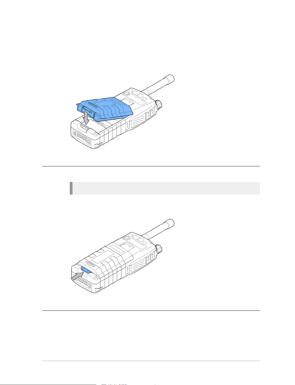
sideways under the belt clip. This may result in damage to the radio and the
belt clip.
To attach the battery, insert the battery into the battery compartment as
shown. Press the battery downwards until it clicks into position.
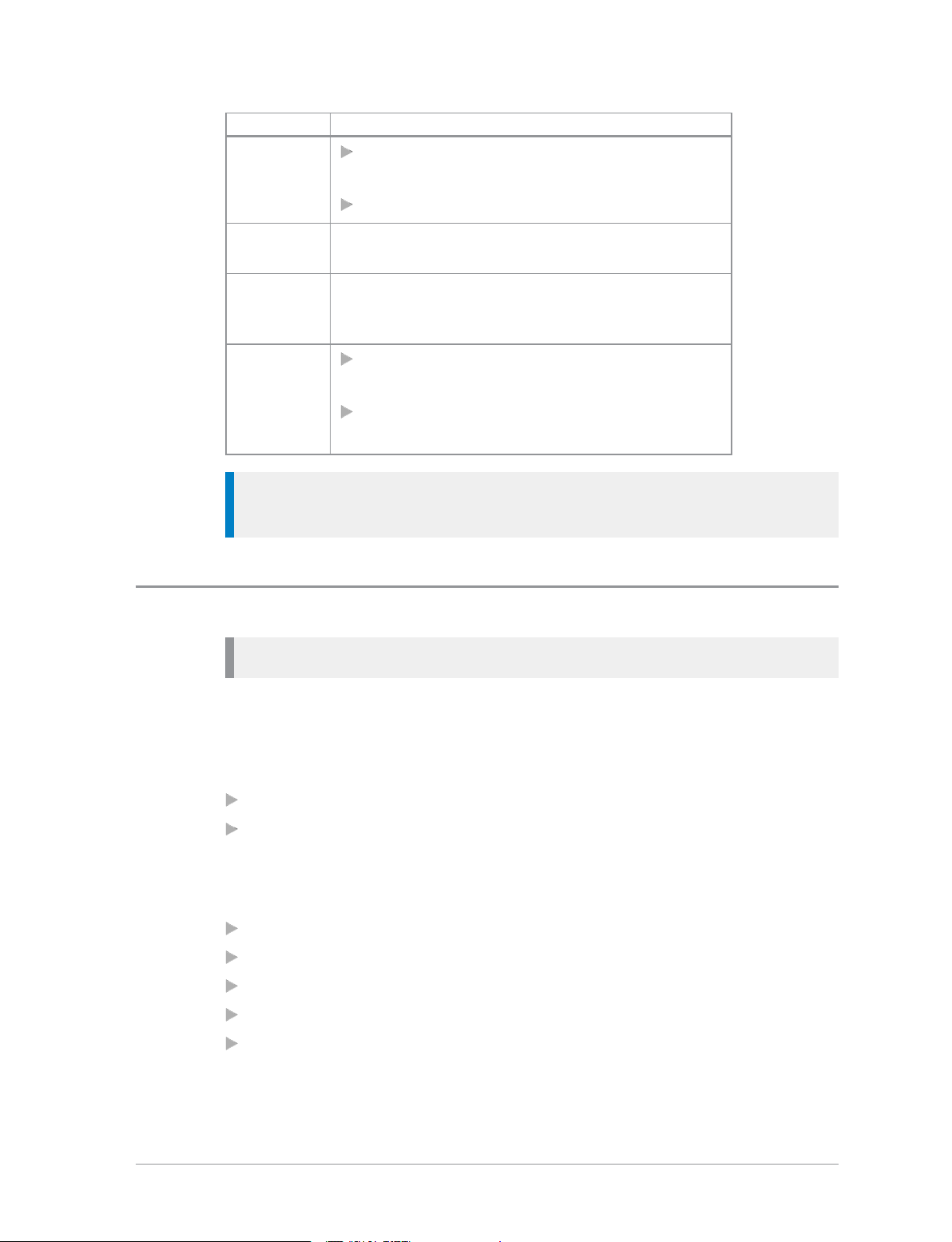
Removing the battery
Caution: Power off before removing the battery.
Push the safety latch on the bottom of the battery. Lift the battery upwards
and remove.
Using Sepura approved batteries
Your radio checks the authenticity of the battery when it is powered on and
has a number of battery management features that only work when a genuine
User Guide
11

Sepura battery is fitted:
the remaining battery charge appears as a percentage when your radio is
powered on [customisable];
battery meter icons, showing the remaining battery charge;
a low battery warning appears when charge is low; and
you can check battery information, such as its authenticity, remaining
charge and serial number [customisable] (see Getting information about your
battery below).
If your radio detects a non-approved battery, the message "Unidentified battery
- powering down" appears. The message is cleared by pressing any key.
If your radio detects a non-approved battery, the message "Unidentified
battery" appears.
If your radio detects a non-approved battery, the message "Unidentified battery
- powering down" and your radio powers off.
Caution: Non-approved batteries may not have inbuilt safety protection
features, and could potentially damage your radio (invalidating your
warranty) and affect your radio's safety and IP compliance ratings.
Getting information about your battery
You can see information about the battery attached to your radio, such as the
remaining battery charge, whether the battery is authenticated (a genuine
PowerTrunk battery) and the battery serial number [customisable].
Select Menu > Options > Battery Information.
The display shows:
Charge—the current remaining charge given as a percentage
Authenticated/Unauthenticated—a PowerTrunk/non-PowerTrunk battery is
fitted
<serial number>—the serial number of the battery
Note: If a non-PowerTrunk battery is fitted, the Charge is reported as 0%,
the battery is marked as Unauthenticated and the serial number is not
shown.
12
HTT-500-2 – 12/2016

Controls & indicators
Your radio has a number of controls and indicators.
Navi-knob
The Navi-knob is a continuous rotating knob that in its normal mode is used
to adjust the volume. The Navi-knob can also be used to perform various
other functions.
To do this… Do this…
Adjust loud speaker volume (or
enable/disable Whisper Mode
[customisable])
Rotate Navi-knob
Move cursor and select characters (in
text entry mode)
Scroll through available talkgroups
Scroll through available Status
Messages
Scroll through available User Profiles
Navigation Keys
Your radio has four navigation keys (left/right/up/down).
Rotate Navi-knob in Text Entry
Mode or Editing Mode
From the Home screen, press
Groups + rotate the Navi-knob
From the Home screen, press
Groups 2 times + rotate the
Navi-knob
From the Home screen, press
Groups 3 times + rotate the
Navi-knob
User Guide
13
Key Action
Use to move the scroll bar up and down to
Up/Down
see more information
Scroll a list of options
Down
Up
Left/Right
Tip: When the display is inverted (flipped upside down) the left and
right navigation keys work in opposite directions.
Soft keys
Note: In P25 Mutual Aid mode, most soft keys are not supported.
Open the top level menu from the Home
screen.
Repeated presses moves upwards through the
options and menu levels until the top level
menu is reached.
Moves between options on the top level
menu.
Moves through the text characters for
selection when writing.
Some keys on your radio may be customised to provide one-touch access to
regularly used features. These programmable keys are referred to as soft keys.
To activate the soft key function:
assigned to a programmable soft key, press and release
assigned to other keys (such as the keypad, Cancel/Home and Select/Send
keys), press and hold for one second
The following keys can be customised as soft keys:
the Select/Send key
the Cancel/Home key
the Emergency Button (if not assigned to Emergency operation)
the programmable side buttons
all radio keypad keys (1–9, *, 0, #,)
14
HTT-500-2 – 12/2016

Note: During full-duplex PSTN/PBX calls, take care when trying to
activate soft keys (designated as 0–9,* and # keys) because they also
generate DTMF tones.
There are many functions that can assigned to a Soft key. Some functions are
activated immediately, such as the keypad lock/unlock or loudspeaker on/off.
There are some special functions that use a ‘navigate to screen’ function. This
means that on activation, a screen displays and you need to take some
additional action, such as activating a SmartMenu where you have to select
an option.
Context keys
Your radio has a left, centre and right context keys which you use to select
options displayed adjacent to them.
Context labels appear at the bottom of the screen, directly above each context
key. These labels show the action of the key when it is pressed; either
activating a feature or performing a function such as clearing a call (Clear) or
selecting an option (Select).
The labels and actions of the context keys in the Home screen are:
Context
key
Left Menu Press to enter the main menu.
Centre
Right Shortcut
Label Action
Groups
Status
Profiles
Press to change the talkgroup. See Selecting a
Talkgroup on page53
Press 2 times to send a status message. See
Inbox on page1
Press 3 times to select a user profile. See User
profiles on page123
Press to open the Shortcut Bar to quickly
access regularly used features or clear a
notification. See Notifications on page30 and
Shortcut Bar on page29
User Guide
15
Note: In P25 Mutual Aid mode the context keys in the Home screen are
fixed as Menu, Channel and Squelch. These are described in P25 Mutual
Aid mode on page105.
Set context key shortcut
The shortcuts available for selection as shortcuts are set during the
customisation of your radio.
Note: You can only use the left and right context keys soft keys on the
top level screen (Home Screen).
To set a context key Home Screen shortcut
1. Open the Home screen.
2. Press and hold the context key until the Context Key Selection box
appears.
3. Navigate to the shortcut in the list and press Select.
The key is reconfigured and the new shortcut label appears in the Home
screen.
Status icons
Icons appear on the status line (at the top of the display) when the radio is
engaged in certain activities or when certain functions are active.
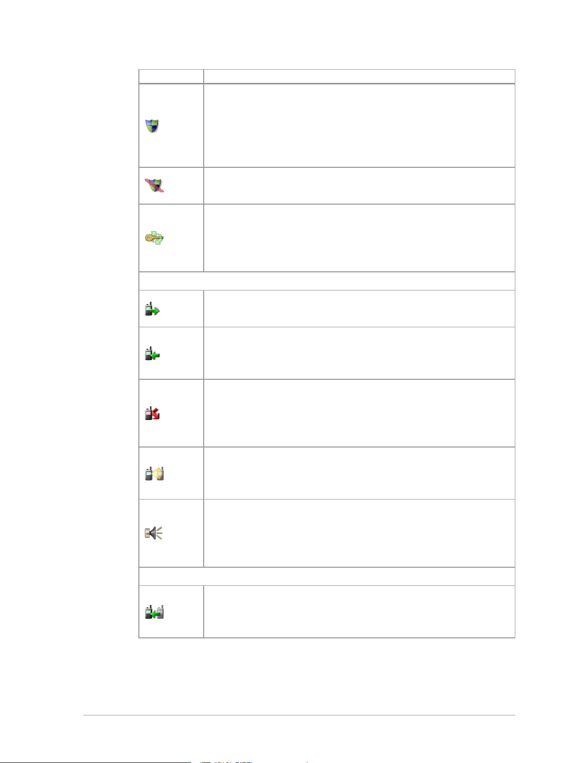
Icon Description
Security and Emergency
Emergency
Appears when emergency operation mode is active on your
radio and an Alarm call is in progress.
Air Interface Encryption disabled
Calls and Callouts will not be encrypted.
16
HTT-500-2 – 12/2016
Icon Description
E2E Encryption enabled
The Secure Communications icon indicates that the selected
talkgroup is customised for End-to-End Encryption. In other
words, calls you make by pressing the PTT button are End-toEnd Encrypted.
E2E Encryption disabled
Indicates that the call is not encrypted.
Key agreement
Indicates that a cryptographic key agreement is in progress
between the radio and the Key Management Centre (KMC)
on the network. (See End-to-End Encryption on page148.).
Trunked Mode Operation (TMO)
Outgoing TMOcall in progress
You are in a call that you initiated.
Incoming TMO call in progress
You are in a call that was initiated by another person or your
dispatcher on the TMO network.
Missed incoming TMO call
You have missed an incoming TMO call. The blue
LEDflashes. A notification alerting you to the missed call
appears in the Shortcut Bar.
Scanning enabled
You radio is scanning (listening) to all available talkgroups
within your scan list for activity.
Broadcast Call
A high-priority group call (point-to-multi-point) initiated by
your Dispatcher to all network radio users. You cannot reply
to the caller.
Direct Mode Operation (DMO)
Incoming DMO call
You are in a DMO call that was initiated by another radio
user.
User Guide
17

Icon Description
Outgoing DMO call in progress
You are in a call to another radio user.
Missed incoming DMO Call
The blue LEDflashes to notify you that you have missed an
incoming DMO call. A notification alerting you to the missed
call appears in the Shortcut Bar.
DMO Repeater detected
Appears when a DMO repeater is detected and the radio can
communicate with any other radios in the selected DMO
talkgroup which are also in range of the repeater.
Repeater ignored
Repeater mode off
General icons
Migrated
Your radio is registered on a Visited Network.
Signal Strength
Shows the current signal strength. More bars indicate a
stronger signal.
Good radio coverage
Indicates good radio coverage.
No service
Indicates poor signal or no radio coverage.
Battery Strength
Indicates the level of charge in your battery. More bars
indicates more charge.
Low battery warning
Appears when there is less than 12% charge remaining in the
battery.
Charging
Appears when the battery is attached to the radio during
charging and the radio is powered on.
Keypad locked
18
HTT-500-2 – 12/2016
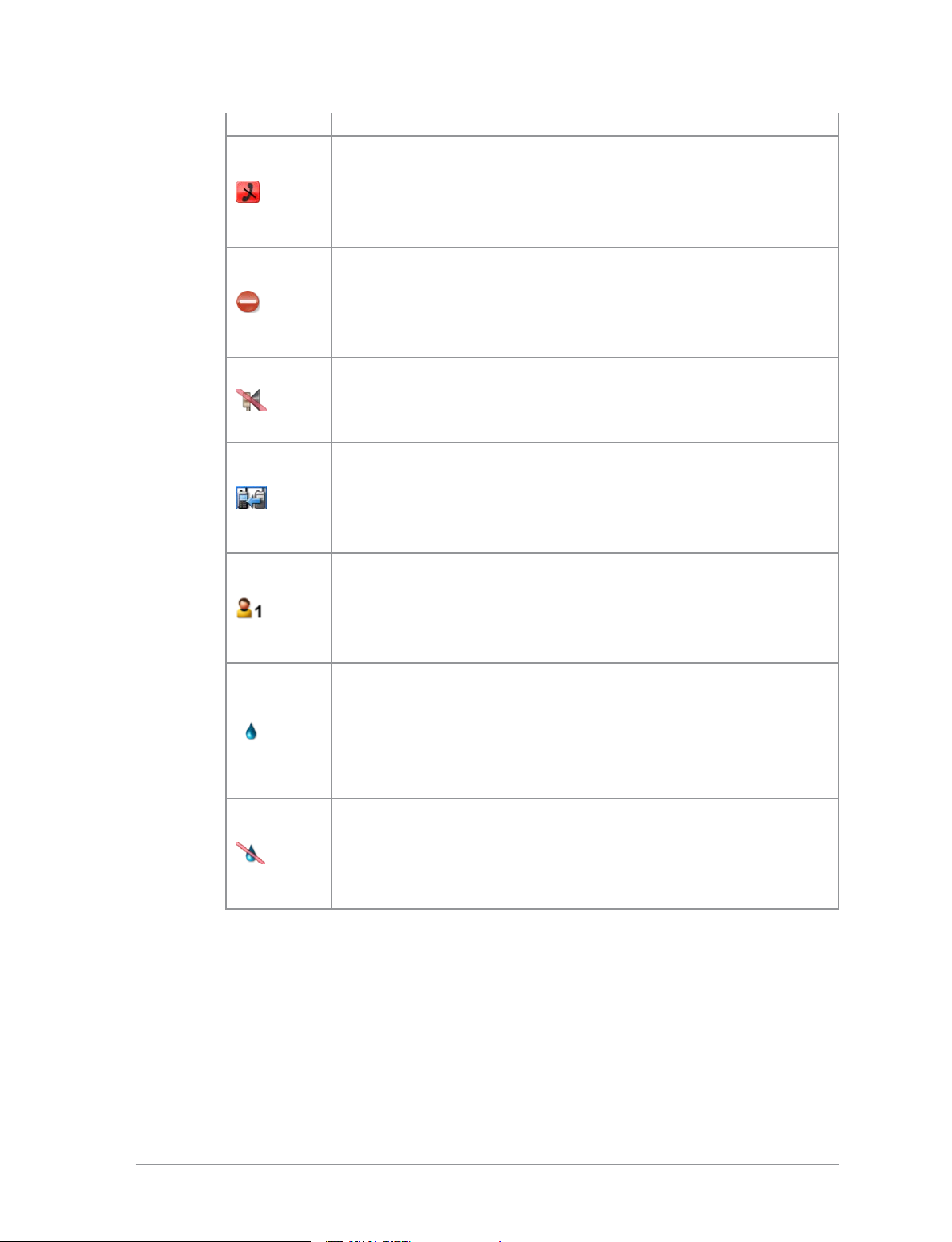
Icon Description
Transmit Inhibit
Indicates that you have activated transmit inhibit and the
radio is unable to transmit (overridden when Emergency
mode is activated).
Privacy mode active during a call
Appears for the duration of a call when Privacy mode has
been activated to prevent any other calls interrupting an
important individual call.
Covert operation mode enabled
The radio turns off any visual and sound alerts, and displays
this icon when covert operation mode is enabled.
Group Focus
Appears when Group Focus is enabled, preventing any calls
from other talkgroups (other than the selected talkgroup)
connecting to the radio.
User Profile
Appears when a user profile is activated. Your radio may be
programmed for a number of user profiles. The number next
to the icon indicates the chosen user profile.
Connector Protection enabled
Indicates that you have enabled connector protection. You
can use your radio in salt water environments without a
cover fitted to the Facilities connector at the bottom of the
radio.
Connector Protection disabled
Indicates that connector protection is disabled. Do not use
your radio in salt water environments without a cover fitted
to the Facilities connector at the bottom of the radio.
User Guide
19
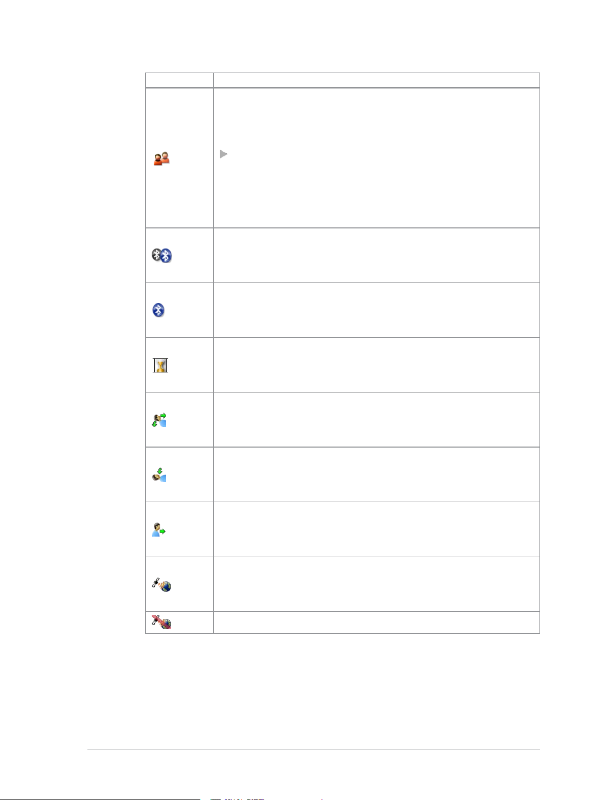
Icon Description
Communication Type Mismatch
This icon appears when there is a mismatch in
communications and is activated when:
a radio within range of a DMORepeater cannot make a
call and attempts to set up a call in DMO instead, the icon
appears on all radios within the talkgroup to indicate that
there are members of the talkgroup who cannot take part
in the call.
Bluetooth® device connected
Appears when you have activated Bluetooth® and have
successfully connected a device.
Bluetooth® on, no device connected
Shows that you have activated Bluetooth® but do not have a
device connected.
Lone Worker protection enabled
Indicates that you have enabled the Lone Worker feature on
your radio.
Man Down motions and tilt sensors active
You have enabled the Man Down feature and the motion and
tilt sensors are active.
Man Down Tilt sensor active
You have enable the Man Down feature, but only the tilt
sensor is activated.
Man Down motion sensor active
You have enable the Man Down feature, but only the motion
sensor is activated.
GPS tracking enabled
Indicates that the GNSS (Global Navigation Satellite System)
function has been enabled.
GPS tracking not available
20
HTT-500-2 – 12/2016
LED indicators
Blue LED
The blue LED indicates either a missed event, such as a missed call or unread
message, or your Bluetooth®status (if enabled). Notifications alerting you to
the missed calls, Callouts or unread messages appear in the Shortcut Bar. See
Notifications on page30.
Note: In P25 Mutual Aid mode the blue LED only indicates Bluetooth
status (if enabled).
LED Indication Description
Flashing on for 1 second,
off for one second, on for
another second, then off
for seven seconds
One flash every 10s Bluetooth®function is enabled
Continuous rapid
flashing
* Not supported in P25 Mutual Aid mode.
Tri-colour LED
The tri-colour LED indicates the operational state of the radio.
LED Colour Description
Solid green Radio is powering on or in a call and receiving
Solid red Radio is in a call and transmitting
®
Missed event*
radio is in Bluetooth®discoverable (visible)
mode
User Guide
Intermittent
flashing red
Flashing orange Incoming telephone call or SDS/Status message
Intermittent four
flashes orange
Attempting to connect to the network or incoming
telephone SDS/Status message or battery low
warning
Transmit Inhibit mode or Fallback mode are active
21

Emergency button
Note: In P25 Mutual Aid mode, emergency operation is not supported
and the Emergency button is disabled.
The red button on your radio is typically programmed to activate an Alarm
Call. See Emergency operation on page36.
Press and hold (2 seconds) the Emergency button to initiate an Alarm Call.
If the radio is powered off, press and hold (3 seconds) to power on and
initiate an Alarm Call. It may take several seconds for the radio to complete its
power on process before initiating the Alarm call.
22
HTT-500-2 – 12/2016

Getting Started
Fitting a microSD card
Note: Your radio supports microSDHC 32 GB cards that must be
formatted for the FAT16 file system.
1. Lift the cover using a small screw driver or tweezers.
2. Carefully lift the metal retainer and insert the card as shown.
Caution: Use care when opening/closing the metal card retainer. If it
becomes detached, it can be clipped back into place.
3. Carefully close the metal retainer.
User Guide
23

4. Close the cover. Using your thumbs, press downward firmly on either side
of the cover as shown to secure each tab. You must ensure that the
compartment cover is secured. Not securing the cover will affect your
radio's IP rating.
Fitting a Smart card
If required by your network operator, you may need to fit a Smart card to
your radio.
1. Lift the compartment cover using a small screw driver or tweezers. The
cover is secured by two tabs located at the top of the cover, either side of
the recess.
24
2. Insert the card into the slot on the underside of the cover as shown,
ensuring that the card is secured between the two tabs.
HTT-500-2 – 12/2016

3. Close the cover. Using your thumbs, press downward firmly on either side
Antenna
of the cover as shown to secure each tab. You must ensure that the
compartment cover is secured. Not securing the cover will affect your
radio's IP rating.
Caution: Your radio must be fitted with an antenna at all times (unless
your radio is used with an external antenna such as an RSM) during
operational periods. Transmitting without an antenna attached my
damage the product. Your radio is designed for use with PowerTrunk
approved antennas.
Always ensure that the seal between the antenna and the radio is maintained.
Never touch the antenna when the radio is transmitting. Ensure your radio
is powered off before fitting or removing the antenna.
Fitting the antenna
1. Insert the base of the antenna into your radio's antenna connector.
2. Rotate the antenna clockwise until it is finger tight. Then apply another 1/4
turn clockwise.
User Guide
25

Removing the antenna
Rotate the antenna counter-clockwise until it can be removed from the radio.
Power on
To power on, press and hold (2 seconds) the Cancel/Home key.
Your radio attaches to the last selected talkgroup when it was powered off (if
it is 'in service').
Depending on your radio's customisation any of the following may display:
the percentage of charge remaining, if a PowerTrunk battery is fitted
a company logo
a splash screen
a welcome screen
a PIN entry screen
Note: A message may be displayed relating to the authenticity of your
battery or attached accessory. A message may appear if your software
licence has or is about to expire.
Note: If your radio supports Radio User Assignment (RUA), which
authenticates your radio on the network, you may be prompted to log on
to your network. See Authentication on page94.
Note: Transmitting in 3W RF is only available when using a PowerTrunk
3W battery. During power on the radio checks the authenticity of the
battery and whether it has the capacity for the radio to transmit 3W RF. A
message displays and the power may be limited if the radio cannot
transmit in 3W RF when licensed to do so.
Power off
Note: Do not power off the radio by removing the battery. The radio
must be powered off correctly to ensure that it performs a controlled
'powered down'.
26
HTT-500-2 – 12/2016

To power off, from the Home screen press and hold (4 seconds) the
Cancel/Home key.
Scroll to the Shutdown option, then press the Select key to power off
your radio. Before powering down, alerts and messages may be sent.
Note: If your radio is configured to provide an option to delete Callouts,
navigate to Shutdown or Delete Callouts then press the Select key.
Locking and unlocking the keypad
To prevent accidental activity during operation, you can lock the keypad.
This will also prevent access to the radio's functions if the radio is stolen.
When the keypad is locked, the Key icon appears in the status line.
The keypad can be locked manually or set to lock automatically after a period
of inactivity.
Note: If customised, your radio's keypad can be locked when an accessory
is attached.
Receiving calls with locked keypad
If you receive a telephone call when the keypad is locked your radio can be
customised so that the Select/Send key can still be pressed to answer it. If the
call is accepted the whole keypad is unlocked. Your radio can also be
customised so that you can press the Cancel/Home key to reject the call and
in this case the keypad remains locked.
Navi-knob with locked keypad
Your radio may be customised so that the Navi-knob is locked when the
keypad is locked. In this case you cannot alter the volume by rotating the
Navi-knob.
Your radio can also be customised so that the Navi-knob remains unlocked
and in this case it can be used for volume control only while the keypad is
locked.
User Guide
27

To lock/unlock the keypad:
Press the * (star) key (or a designated soft key), then press the OK context
key to lock/unlock the keypad.
Tip: To quickly lock and unlock the keypad, press and hold (2 seconds)
the * (star) key.
If you press any other key while the keypad is locked no action is taken. The
Navi-knob remains unlocked when the keypad lock is enabled. A message is
displayed to remind you that the keypad is locked.
Alternatively, you can:
1. Select Menu > Options > Settings > Keypad Lock.
2. Press Lock to lock the keypad.
Setting the radio to automatically lock the keypad
You can set the radio to automatically lock the keypad after a period of
inactivity.
1. Select Menu > Options > Settings > Timed Keypad Lock.
2. Press Toggle to enable/disable auto keypad lock.
Home screen
The top level screen, known as the home screen, appears when the radio
powers on and when it is idle.
Note: In P25 Mutual Aid mode the Home screen is simplified. See P25
Mutual Aid mode (described on page105).
Tip: To quickly get back to the home Screen, press and hold (2 seconds)
the Cancel/Home key.
The status line, at the top of the screen, displays various icons to indicate the
state of operation or when certain functions such as keypad lock have been
activated. It can also be configured to display the Network Name when the
radio is idle.
28
HTT-500-2 – 12/2016

The context key labels at the bottom of the screen indicate what the context
key directly below the label is configured to do. These labels change
according to where you are in the menu hierarchy.
# Description
Status line showing the radio coverage signal strength, battery
1
charge indicators, and operational status icons.
Information area containing information that only appears on the
Home screen. This is customised by your service provider or
2
organisation. It may show date and time, your selected talkgroup,
folder and network name (Mobile Network Code Alias).
3
Context key options (available in the Home screen).
Shortcut Bar
You can easily access commonly used radio features such as your Inbox, and
turn features on and off using the Shortcut Bar. The Shortcut Bar can contain
up to 5 radio features and some of these can be paired with notifications to
alert you to a missed call or a new message in your Inbox.
To open the Shortcut Bar, in the Home screen press the Shortcut context key.
User Guide
29

# Description
Use the navigation keys to scroll through the notifications and
features. Notifications always appear to the left of features. Press the
1
Right navigation key to continue scrolling right to view more
shortcuts (if available).
To open a notification or feature, highlight it and press the Select
2
context key.
Press the Back context key to close the Shortcut Bar without opening
3
a feature.
Notifications
Like a smart phone, your radio can display notifications to indicate a missed
call or new message. They also appear when certain functions are enabled
such as mute and transmit inhibit. Your radio can display up to 5
notifications, and up to 5 shortcuts commonly used radio features.
Some features can be paired with notifications, such as your Inbox so when a
message is received a notification appears in the Shortcut Bar to alert you to
the unread message. When paired with a feature, the feature icon appears
with a notification badge .
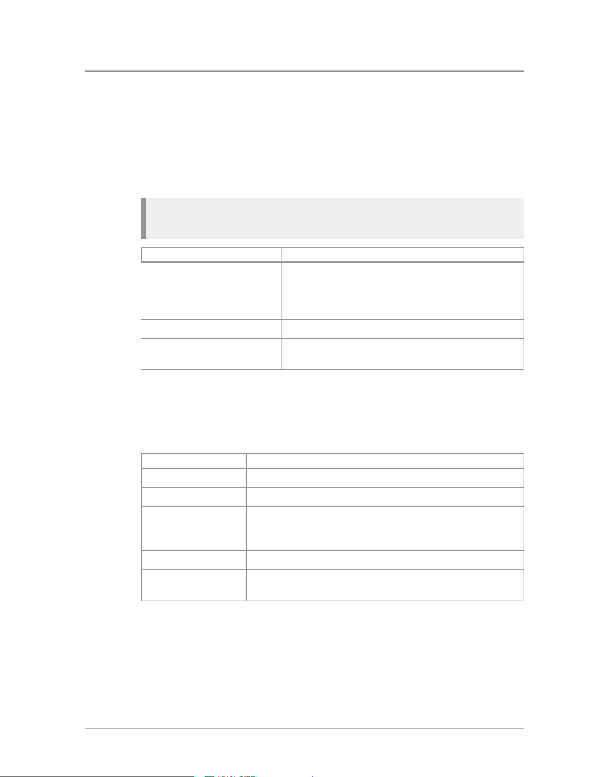
The following notifications can be paired with a feature:
Icon Notification Paired Feature
Unread message Inbox
Missed call Call History
Missed Callout Callout
# Description
1
2 Example notification of a change of state (Transmit Inhibit).
Notifications paired with features appear to the left of all other
feature icons.
30
HTT-500-2 – 12/2016

3
Shortcuts to commonly used features always appear to the right
of notifications. Scroll right to see more features (if any).
Menu
4
To close a notification:
From the Home screen, press the Shortcut context key, highlight the
notification then press the Select context key. Use the feature in the usual
way, for example, read an unread message or respond to a missed call. The
notification automatically closes and disappears from the Shortcut Bar.
Your radio is customised by your service provider or organisation with a
number of features that are accessed from the main menu.
To open the main menu, in the Home screen press Menu.
To open a sub-menu or menu option, scroll to the option (highlight it) and
press Select.
To return to a higher level menu, press Back.
In the Home screen, press the Shortcut context key to access the
notification.
To return to the Home screen at any time within the menu hierarchy,
press and hold (2 seconds) the Cancel/Home key.
Menu options
The following icons are used to identify the sub-menus that provide access to
further options.
Icon Menu option
Phone
Add, edit and delete your personal contacts within your personal
folder. Search (or filter) your contacts to locate the contact you
want and initiate a call. Review you call history.
Messages
Read, create, save and send text (SDS) messages. View picture
messages (if customised). Select and send a status message. Clear
your mailbox of unwanted messages.
User Guide
31

Icon Menu option
Groups
Search your talkgroup folders and select a talkgroup. Enable
scanning of your selected talkgroups. Set up your speech call
settings.
GPS
Manage your GPS location and position settings. View your
current location, direction and speed.
Applications
Your radio may be customised with a number of applications such
as Man-down and Lone Worker. Your service provider or
organisation may have installed specific applications (Short Data
Applications) to help you in your role. Access WAP sites.
Networks
Manage your network connections and DMO options. Change
your operating mode (TMO/DMO/Repeater). Enable/disable
Transmit Inhibit mode when working in RF sensitive areas.
Options
Manage your Bluetooth® devices and settings. Personalise your
radio settings such as backlight, text size and language. Enable
Connector Protector when working in salt laden environments to
protect your radio.
User Profiles
Select customised profiles designed specifically for the way you
work.
Help
View help, such as a list of customised soft keys on your radio.
32
HTT-500-2 – 12/2016

Menu Structure
SmartMenus
SmartMenus are designed to provide quick access to regularly used radio
features, usually with a common theme. Your service provider or
User Guide
33

organisation may customise your radio with a number of SmartMenus, for
example you may have a SmartMenu containing all your Quick Status
messages, another for user profiles and another for selecting operational
modes such as toggling on/off covert mode, Transmit Inhibit, loudspeaker
mute and so on.
SmartMenus are assigned to a soft key, either a Side key or one of the keys on
the keypad. To open a SmartMenu, press the Side key or press and hold (1
second) the assigned key on the keypad.
Help
Use the navigation keys to scroll the list of options on the SmartMenu.
Options are labelled with a number, shown to the right of the option. To
select the option, press the key that corresponds to the number of the option,
for example to select option 3, press the 3 key. Note that using this method
only options numbered 1 to 12 can be selected using the keys on the keypad
(press 0 for option 10, the Star (*) key for option 11 and the Hash (#) key for
option 12). For options numbered 13 onwards, scroll to the option (highlight
it), and press Select.
The Help menu displays a free text area which is usually customised to
indicate radio soft key assignments. It may also be used to record any
required help text.
To access help
Use one of the following:
34
HTT-500-2 – 12/2016

Press the Up navigation key (or Shortcut) to open the Shortcut Bar, then
select Help.
Press a dedicated soft key (default is normally key ‘0’ zero).
Press Menu > Help.
User Guide
35

Emergency operation
Note: In P25 Mutual Aid mode, emergency operation is not supported
and the Emergency button is disabled.
Emergency operation is available in TMO and DMO if the radio is in service.
If your radio is customised for Gateway and Repeater modes, it will make an
Alarm call in TMO. If it cannot make the call in TMO the radio will
automatically switch to DMO to make the call.
The red button on the top of your radio can be programmed to initiate an
Alarm call at any time when your radio is in operation. This button is known
as the Emergency Button.
Your radio may be customised to perform one or more of the following:
Initiate an Alarm call set up to one or more pre-defined users (typically to
your dispatcher and other members of your talkgroup) and/or;
Send an Emergency Status message to an individual, the dispatcher or a
talkgroup and/or;
Send a position report (GPS dependent).
If you are working in RF sensitive areas and have enabled Transmit Inhibit,
prohibiting radio transmission, initiating an Alarm call will override the
Transmit Inhibit feature and the Alarm call will be transmitted.
Your service provider or organisation can provide information on how your
radio is customised for Alarm calls and how to operate your radio in
emergency situations. If you are working in a sensitive environment your
radio may be customised for Silent Alarm calls where audible and display
alerts are disabled, or your radio may be customised for Live Microphone that
allows you to call for assistance hands-free without pressing the PTT button.
Silent Alarm Call
If you are working in sensitive environments where the audible and display
alerts associated with an Alarm call are inappropriate, your radio can be
customised to make a Silent Alarm call (without acoustic or screen alerts).
36
HTT-500-2 – 12/2016

Silent Alarm calls cannot be activated when operating in Lone Worker or
Man Down modes.
When a Silent Alarm call is made, the radio displays the Home screen with
the talkgroup associated with call. During the call you may navigate away
from the Home screen.
Live Microphone feature
Your radio may be customised with the Live Microphone feature. This feature
allows you to broadcast a call for assistance hands-free for a specified period
of time and without having to press the PTT button. The radio automatically
cycles between transmit and receive communication during a programmed
period of time (seconds). Live Microphone is cancelled when the time expires
or by pressing the PTT button.
Making an Alarm call
You can still make an Alarm call if the keypad is locked.
To make an Alarm call
1. Press and hold (2 seconds) the Emergency button; a confirmation beep
sounds.
2. Release the button and speak into the microphone.
During an Alarm call:
the microphone is ‘live’ for a programmed period (seconds) allowing you
to speak hands-free without pressing the PTT button (customisable)
the LED illuminates solid red
your radio sounds audible tones
a large emergency symbol appears on the screen
your identity and talkgroup appears on the display of those receiving the
Alarm call
Receiving an Alarm call
An Alarm call overrides any existing calls on the talkgroup.
User Guide
You know you are receiving an Alarm call when:
37

your radio sounds an audible tone
the LED flashes red
the emergency symbol appears on the screen
your radio status changes to Emergency
Clearing an Alarm call
You can only clear an Alarm call that you have initiated.
To cancel the Alarm call, press the Clear context key.
To cancel the Alarm call, press the Call Clear key, the Clear context key or
the Cancel/Home key. Alternatively, press and hold the Emergency button (2
seconds).
Warning: Depending on which network is being used, if the TETRA
Alarm call is a group call, then—although both of the TETRA Alarm
call exit functions will clear the TETRA Alarm call on the call
originator’s radio—it will not remove the alarm from the system.
Radios alerted to the emergency may, depending upon the
infrastructure configuration, remain in the TETRA Alarm call
condition until the dispatcher clears the call from the system.
When the Alarm call is cancelled, your radio returns to the talkgroup that
was selected before the call was initiated.
Power on Alarm call
If your radio is powered off, press and hold (3 seconds) the Emergency
button to power on and initiate an Alarm call. Any customised Welcome
screen is not displayed during power on. If your radio is customised for PIN
entry, you will need to enter your PIN before the alarm call is initiated. It may
take several seconds for the radio to complete its power on process before
initiating the Alarm call.
38
HTT-500-2 – 12/2016

Note: If your radio supports Radio User Assignment (RUA), which
authenticates your radio on the network, you may be prompted to log on
to your network before the Alarm call is initiated. Contact your service
provider for information. See Authentication on page94.
User Guide
39

Sound
Your radio is equipped with a loudspeaker for use during PTTcalls and a low
level speaker for use during telephone calls. You can adjust the volume of the
speaker and increase the sensitivity of the microphone (see Whisper mode
below) so that you can speak more quietly. Your radio also uses sound to alert
you to the various operational states.
Adjusting the volume
Rotate the Navi-knob to adjust the volume. A vertical volume meter displays
to indicates the current volume level. The radio sounds an audible tone at the
new volume level.
Loudspeaker on/off
Tip: A soft key may be customised to toggle the speaker on and off.
1. Select Menu > Options > Settings > Loudspeaker ON/OFF.
2. Press Toggle or press the Select/Send key.
Whisper mode
Whisper mode allows you to talk more quietly than normal but still be heard
and understood by the person you are calling. It can be useful to switch to
Whisper mode when providing confidential information.
Note: If you select a User Profile which already increases the sensitivity of
the microphone, depending on your radio's customisation Whisper mode
may not increase the sensitivity further.
To enable Whisper mode
Depending on customisation, to enable Whisper mode, you can:
40
HTT-500-2 – 12/2016

press a programmed soft key
rotate the Navi-knob to decrease the volume to below its lowest level
The radio sounds a low-high level alert when Whisper mode is enabled.
To disable Whisper mode:
Depending on customisation, to disable Whisper mode, you can:
press a programmed soft key
increase the volume until the volume level meter displays at least the
minimum level
increase the volume to its loudest level then attempt to increase the volume
further
The radio sounds a low-high level alert when Whisper mode is disabled.
Audible tone alerts
Certain events on your radio initiate audible tone alerts. These alerts are
attenuated when you select a user profile which uses covert mode (see User
profiles on page123).
1. To toggle audible alerts
2. Select Menu > Options > Alerts > Audio Alerts.
3. Press Toggle (or the Select/Send key) to toggle alerts on/off.
Note: If your radio is turned off with Audio Alerts disabled they remain
disabled when the radio is next switched on.
User Guide
41

Vibration alerts (Haptics)
Your radio can provide vibration alerts and haptic feedback to help you
recognise certain events, such as when a key is pressed, for example in a dark
environment, or when you are wearing gloves.
To toggle vibration alerts
1. Select Menu > Options > Alerts > Vibrator Alerts.
2. Select one or more of the following options:
Vibrator (Voice)—vibrate on incoming individual half-duplex or fullduplex calls
Vibrator (Data)—vibrate on incoming SDS or Status messages
Vibrator (Alarm Key)—vibrate when Emergency Button is pressed
Vibrator (Key Press)—vibrate when any key (except Emergency Button
and PTT) is pressed
3. Press Toggle or the Send/Select key to enable/disable it as required.
4. To return to the Display Settings menu press Back or the Cancel/Home
key.
Tip: To stop the radio vibrating when a voice call is received, press a
Context key or the Select/Send or Cancel/Home key.
42
HTT-500-2 – 12/2016

Personalising your radio
You can personalise your display settings (such as text size, backlight,
inverting the screen and change languages) and create a personal phone book
containing your own contacts.
Invert the display
When you are wearing the radio on your shoulder, attached to a belt or to a
body vest, you may want to flip the display upside down to make it easier to
read. The Invert Display option rotates all screen elements (apart from the
Context key labels) by 180 degrees.
Tip: This feature is commonly assigned to a soft key or SmartMenu.
To invert the display:
1. Select Menu > Options > Settings > Display Settings > Invert Display.
2. Press the Toggle context key. When a tick appears in the check box, the
display is flipped, and when the check box is empty the display is set to
normal.
Note: When the display is inverted, the navigation keys work in opposite
to their normal function. Press the Up key to scroll down and the Down
key to scroll up. The Right key to scroll left and the Left key to scroll right.
Adjusting the backlight
When a call or message is received, and when you press any key, the
backlight lights up the display and keypad. The length of time the backlight
illuminates is set during customisation.
User Guide
43

To adjust the backlight:
You can toggle the backlight on/off from the Shortcut Bar, by using a soft key
or from a SmartMenus on page33 (if customised).
Alternatively:
1. Select Menu > Options > Settings > Display Settings > Backlight.
2. Press the Toggle context key.
To adjust brightness:
1. Select Menu > Options > Settings > Display Settings > Day/Night Mode.
2. Select Backlight Level.
3. Rotate the Navi-knob to adjust the intensity of the backlight and the
keypad illumination on a scale of 1–7 (max.).
Day/Night mode
When a call or message is received, and when you press any key, the
backlight lights up the display and keypad. A bright display can be a potential
distraction, particularly when driving at night or in poor lighting conditions.
Day/Night mode lets you adjust the intensity of the backlight and keypad
illumination to suit your working conditions. Night mode reduces the glare
from the display, making it ideally suited for when the radio is cradled in a
vehicle at night time. Night mode reduces the glare from the display, making
it ideally suited for night time use.
44
When the preferences for day and night mode have been set, switching
between the modes automatically adjusts the backlight and display settings.
To change Day/Night mode settings
1. Select Menu > Options > Settings > Display Settings > Day/Night Mode.
2. Scroll to each option (highlight it) to make your adjustments:
Day Mode—to toggle between Day Mode and Night Mode press the
Toggle context key.
Backlight Enabled—to toggle the backlight on/off press the Toggle
context key. When a tick appears in the box, the backlight is on, and
when the box is empty, the backlight is off.
Backlight Level—to adjust the intensity of the backlight and the key
pad illumination on a scale of 1 to 7 rotate the Navi-knob.
HTT-500-2 – 12/2016

Tip: A soft key may be customised to switch between Day/Night mode.
Adjusting text and icon size
Your radio uses the default size for the text and icons set during
customisation, however it also supports a number of different size modes that
control how text and icons are displayed, which can make them easier to see
from a distance.
Caution: When selecting larger modes, some prompts or icons may not
appear on the radio display.
Your radio supports the following modes:
Normal Mode allows the maximum amount of information available to be
displayed in a compact character size.
Large Mode displays screen information in a large character size.
Very Large Mode displays the talkgroup number or talkgroup name, as
customised, in an extra large size on the Home screen with all other screens
in Large mode.
Custom displays the Home screen, menu and WAP browser in predefined
text sizes set during customisation. Only the Home screen supports Very
Large mode, with other screens set to either Normal or Large mode.
Note: Depending on the customisation of the Home screen, if the date is
shown on the Home screen it may be truncated in Very Large Mode. If
the date format YYYY.MM.DD is used, then the day does not display.
To change text mode:
1. Select Menu > Options > Settings > Display Settings > Text Size.
2. Use the Up and Down Navigation keys to highlight the mode and then
press the Select context key.
The radio displays the Home screen, with the text and icons appearing in the
chosen mode.
User Guide
45

Setting the display language
Your radio operates in the language chosen during customisation and can
support two display languages. The display uses the default language if the
radio is only customised for a single language, or the currently selected
language if two languages are programmed.
To change the language:
Tip: Your radio may be customised with a soft key or provide an option
on a SmartMenu to change the display language. See SmartMenus
(described on page33)
1. Select Menu > Options > Settings > Language.
2. Scroll to the language option, and then press the Select context key.
The Home screen appears and the display shows the selected language.
Menu style
Grid style
You can display the menu in Grid, List or Compatibility style.
1. Select Menu > Options > Settings > Display Settings > Menu Style.
2. Select one option:
Grid—set Grid menu style
List—set List menu style
Card—set Card (Compatibility) menu style
46
HTT-500-2 – 12/2016

List style
highlight items using the four navigation keys
to open an item press Select
to return to the top level screen press Cancel or Cancel/Home key.
highlight items using the Down and Up navigation keys.
to open an item press Select
to return to the top level screen press Cancel or the Cancel/Home key.
Compatibility style (card)
highlight items using the Left and Right navigation keys
to open an item press Select
to return to the top level screen press Cancel or Cancel/Home key.
User Guide
47

Time and Date
Your radio can be customised to display the current time and date on the
Home screen. The time is shown in 24 hour format. The day and month
appear in alphanumeric characters, for example Wednesday, 20 May. Your
radio may be customised to use shortened forms for the day (Wed.).
To view and edit the time and date
1. Select Menu > Options > Settings > Time and Date.
2. Press Edit or press the Select/Send key.
3. Enter the digits required (see Text entry on page81).
4. Press OK or the Select/Send key to save your changes; press Cancel or the
Cancel/Home key to abandon your changes.
48
HTT-500-2 – 12/2016

Talkgroups and folders
Talkgroups are pre-programmed onto your radio. Each talkgroup typically
contains users who have a similar role or who are within a distinct location or
who provide a service that you would use. They are organised into folders to
help you quickly select one that is applicable to your environment or
situation.
A folder can contain both DMO and TMO talkgroups, but only those
talkgroups applicable to the current operating mode, either DMO or TMO,
appear when a folder is opened. In TMO, only those talkgroups available on
the current network are displayed. The folders available depend on the
customisation of your radio; various ‘special’ folders are also programmed
into your radio (see Special folders on the next page).
Tip: If you want to change from a DMO talkgroup to a TMO one, you
need to change the operating mode first (see Operating Modes on page98).
A top level folder can have a number of sub-folders, similar to a folder
structure on a computer, and a folder can contain both folders and
talkgroups. If a folder contains sub-folders and talkgroups, two tabs appear—
one for sub-folders and the other for talkgroups. You can use the Left
or Right navigation keys to switch between the tabs.
Your radio may be customised for Talkgroup Selection Mode or Folder Selection
Mode. How you select a talkgroup depends on which mode your radio is
customised to use. When you select a talkgroup, the radio attaches to that
talkgroup. Your radio can only participate in calls with talkgroups it is
attached to via the network. When ongoing calls are detected on any
talkgroup your radio is scanning you can join in by pressing the PTT.
When the radio is attached to a talkgroup, the talkgroup and folder appear on
the Home screen (see Home screen on page28). If a talkgroup and folder are
not shown:
the radio may not have attached to the last used talkgroup at power on, or
it was attached to a DGNA talkgroup which has been deassigned, or
User Guide
49

it may be attached to hidden background talkgroups, or
a folder has not been selected (Folder Selection Mode only), or
a change of network may have occurred and the last used talkgroup may
not be usable on the current network.
When your radio is powered on, if possible it re-selects either the default
talkgroup or connects to your last selected talkgroup.
Special folders
In addition to the ‘standard’ folders created to contain your talkgroups, your
radio can be customised with Special folders. Special folders can only contain
talkgroups (they cannot contain folders). Some Special folders are
continuously scanned, and when ongoing calls are detected you can join in
by pressing the PTT.
The following special folders may be programmed into your radio during
customisation:
Favourites—frequently used talkgroups that can be added to the folder
during customisation or added by the user.
All—contains every talkgroup programmed into your radio including
those in special folders. Only available on radios customised for Talkgroup
Selection mode.
DGNA—contains up to 50 dynamically assigned groups. The contents are
automatically maintained by the radio and are not customisable in
Talkgroup Selection Mode. You can select a DGNA talkgroup. In Folder
Selection Mode, the scan state (scanning enabled or disabled) of a
talkgroup can be changed and the folder can be emptied using the Folder
Restore option.
UDSL—user-defined scan list(s), see User Defined Scan Lists on page56. A
list of talkgroups which you can modify yourself. If you select a UDSL
instead of a specific talkgroup your radio scans all the talkgroups in that
UDSL. Until a UDSL is selected its talkgroups are not scanned for
activity. For more information see User Defined Scan Lists on page56. Only
available on radios customised for Talkgroup Selection mode.
Always attached—talkgroups which the radio scans continuously for
activity. A talkgroup in this folder can be selected as the requested
talkgroup in Talkgroup Selection Mode.
50
HTT-500-2 – 12/2016

Background—talkgroups which the radio scans continuously for activity.
You cannot select a background talkgroup in this folder as your requested
talkgroup.
User Guide
51

Typical folder arrangement
The following illustration shows how the folders can be used to organise
talkgroups:
52
HTT-500-2 – 12/2016

Talkgroup Selection Mode
When the radio is customised for Talkgroup Selection Mode, the selected
talkgroup becomes the requested talkgroup to which you make calls.
You can insert frequently used talkgroups in the Favourites folder, making it
quicker and easier to change your talkgroup. Additionally your radio may be
customised for Quick Groups that allow you to change to a frequently used
talkgroup using a soft key.
You can create your own user defined scan lists that are saved into the UDSL
special folder. The UDSL folder ‘greys out’ (disables) talkgroups that are
invalid for the current network. The scan list allows you to set scanning
priorities on the talkgroups, so the radio can prioritise calls between the
scanned talkgroups. See User Defined Scan Lists on page56.
Selecting a Talkgroup
You can use one of the following methods to select a talkgroup:
From the Home screen, press Groups.
From the Menu navigate to the Groups menu.
Use a soft key to return to your Quick Group.
Note: Talkgroups in the Smart Call Folder-1 or Smart Call Folder-2 folders
can only be accessed when the appropriate Smart Call mode has been
selected from the Speech Call Settings screen or by using a soft key. (See
Smart Calls on page78.)
1. From the Home Screen, press the Groups key. The current selected folder
and talkgroup appear in the talkgroup selection box.
Tip: If you want to change to another talkgroup within the same
folder, simply enter the number of the talkgroup, or select the All
Folder which contains all the talkgroups and enter the number of the
talkgroup.
User Guide
53

2. Use the Left and Right navigation keys to move between folders at the
same level. Use the Up and Down navigation keys to move between the
folder levels (sub-folders).
Rotate the Navi-knob to scroll through the talkgroups within the currently
selected folder. The directional arrows under the talkgroup name indicate
the rotational direction of the Navi-knob.
3. Press the Select context key to attach to the talkgroup.
Opening a folder
1. Select Menu > Groups > Folders.
2. Highlight a folder and press Open.
Tip: To navigate back ‘up’ the folders list, press Back.
Searching for folders and talkgroups
You can search for talkgroups or folders by filtering on a text string. Items
which do not match the string are temporarily ‘filtered out’ of the list.
You can use either:
Search card—to filter the current talkgroup/folder folder.
Search all—to filter across all talkgroups and folders
1. To search inside a specific folder, open that folder.
2. Press Options then select Search card or Search all.
3.
Enter characters you wish to filter against (see Text entry on page81).
The list of matching names is dynamically filtered as characters are
entered. Only matching talkgroups or folders remain in the list.
4. To cancel the filter operation select the Stop search option.
Inserting a talkgroup into a folder
If a folder is editable you can use the Insert option to insert a talkgroup into
it.
54
HTT-500-2 – 12/2016

Deleting a talkgroup from a folder
If a folder is editable you can use the Delete option to remove a talkgroup
from it. The talkgroup can still be selected from the All folder if customised,
or by entering the talkgroup number directly in the Talkgroup Selection box.
Create a ‘favourite’ talkgroup folder
To quickly access frequently used talkgroups, you can add them to the
Favourites folder.
1. Select Menu > Groups > Folders > Favourites.
2. Press Options, then select Open.
3. Navigate to the New Group option then press Options.
4. Press Insert.
5. Select the talkgroup you want to add (from any folder).
6. Press Select to insert the talkgroup into the Favourites folder.
Tip: If the New Group option is not available, you do not have 'edit'
permissions on the Favourites folder. The Favourites folder must be set to
'Edit' at customisation.
Quick Groups
You can quickly change to a different talkgroup by pressing a customised
Quick Group soft key specified for that talkgroup.
To select the Quick Group talkgroup
Press the customised Quick Group soft key. Alternatively, view the Quick
Group using the menu then press Select.
To view your Quick Groups
You can view the talkgroups and folders associated with your assigned Quick
Groups.
1. Select Menu > Groups > Quick Groups.
2. Use the Up and Down navigation keys to highlight a Quick Group then
press Select.
To change the talkgroup associated with a Quick Group
Your radio can be customised to allow you to change the talkgroup associated
with a Quick Group.
User Guide
55

Note: These changes may be overwritten when your radio is
reprogrammed.
Select and view a Quick Group (described in To view your Quick Groups on the
previous page) then:
Select Options > Change > Current.
Your current talkgroup is now associated with the selected Quick Group.
User Defined Scan Lists
A User Defined Scan List (UDSL) is a list of talkgroups which are either fixed,
or user-definable. Any talkgroups in the UDSL that are invalid for the current
network are disabled and are shown ‘greyed out’ in the talkgroup list.
Until a UDSL is selected the talkgroups it contains are not scanned and your
radio cannot receive calls from them. Your radio can have a maximum of 20
UDSLs, and up to 10 talkgroups can reside within each UDSL.
If you select a UDSL (in the same way as you select a talkgroup, see Selecting a
Talkgroup on page53):
the talkgroups it contains are scanned, allowing your radio to receive calls
from any of the talkgroups in the UDSL
the UDSL icon is displayed in the right hand corner of the radio
display
calls are made to the talkgroup designated as the 'selected talkgroup'. If
there is no selected talkgroup in the UDSL, calls are made to the talkgroup
with the highest priority.
Each talkgroup in a UDSL can have up to three different levels of userdefinable group scan priorities which are used by your radio when deciding
which call to follow when a call on one talkgroup is active and a call on
another talkgroup is received. The scan priority of each talkgroup in a UDSL
is shown at the right hand side of the screen as (High), (Normal) or
(Low). You can designate a selected talkgroup in each UDSL. You can add
and remove talkgroups from a UDSL.
56
HTT-500-2 – 12/2016

View and edit scan list
1. Select Menu > Groups > Scan Lists.
2. Use the Up and Down navigation keys to select one of the UDSLs and
press Open.
3. Press Edit.
Change default (selected) talkgroup
1. Use the Up and Down navigation keys to select one of the talkgroups in
the UDSL.
2. Select Edit > Options > Select.
3. Select Edit > Options > Save.
Add a talkgroup
1. Press Options > Add.
2. The talkgroup selection box is activated. Select a talkgroup as described in
Selecting a Talkgroup (described on page53) then press Select.
3. Select Edit > Options > Save.
Remove a talkgroup
Select the talkgroup you wish to remove then:
1. Select Edit > Options > Delete.
2. Select Edit > Options > Save.
Changing group scanning priority
1. Select Edit > Options > Change Priority.
2. Select scan priority (High), (Normal) or (Low) then press Select.
3. Select Edit > Options > Save.
User Guide
57

Scanning ON/OFF
Scanning of talkgroups can be enabled and disabled. If scanning is disabled,
the radio will ignore incoming calls on these talkgroups. Your current
talkgroup is always scanned.
Note: Background talkgroups are always scanned and will continue to be
scanned when scanning is disabled.
1. Select Menu > Groups > Scanning ON/OFF.
2. Press Toggle (or the Select/Send key) to enable/disable scanning.
Folder Selection Mode
When the radio is customised for Folder Selection Mode, you need to select a
folder, which is typically configured with zero or one selected TMO
talkgroup and/or one selected DMO talkgroup, which the radio users to make
calls. The selected talkgroup can be changed at any time.
The current folder and talkgroup appear on the Home screen when a folder is
selected, and a talkgroup within that folder is selected as the requested
talkgroup. If a folder is not selected when the radio powers on, the message
'No Folder' appears on the Home screen. When a folder is selected that does
not have a selected talkgroup, the message 'No Selected Group' appears.
All the TMO talkgroups within the selected folder that are scan-enabled1and
valid for the current network contribute to the scan list that the radio uses to
prioritise calls. If a talkgroup is editable2you can change its scan state (to
enable or disable scanning), change its scanning priority (see Scanning
talkgroups on page61) and select or deselect it.
A talkgroup can be copied from a folder to another editable folder3, for
example you can copy talkgroups from Special folders such as the Always
Attached folder into a generic folder and copy frequently used talkgroups to
the Favourites folder, making it quicker and easier to change your talkgroup.
1
In Radio Manager folder properties, the talkgroup option In Scan List is selected.
2
In Radio Manager folder properties, the talkgroup option Editable is selected.
3
In Radio Manager folder properties, the Subject Content option is set to Edit.
58
HTT-500-2 – 12/2016

Your radio may be customised for Quick Folders, which allow you to quickly
change to a frequently used folder using a soft key.
Opening the current folder
Use one of the following methods to open the current folder:
From the Home screen, press Groups, then press Select.
From the Menu navigate to the Groups menu, and then press Select then
select Folders.
Tip: To open another folder, press Back to navigate back 'up' the folders
list. Select the folder you want to open and press Open.
Selecting a folder
You can select a folder from the folder list, where the current selected folder
is identified by the icon. You cannot select the DGNA, Always Attached,
Background or Smart Call folder as your selected folder.
Additionally, you can select a folder by pressing a soft key to select a Quick
Folder or select a folder by entering its Folder ID (see Selecting a folder using
the folder ID below) if customised.
Tip: A talkgroup within the folder must be selected before you can make
calls. See Selecting a talkgroup on the next page.
To select a folder:
1. From the Home screen, press Groups, then press Select to open the
current folder.
2. Press Back to navigate back 'up' the folders list.
3. Scroll to the folder (highlight it) and press Options, then scroll to the
Select option and press Select.
Note: Only talkgroups which are valid for the current network are listed
in the folder.
Selecting a folder using the folder ID
Every folder has a unique identification number (ID) and you can use this
IDto quickly select the folder.
User Guide
59

Press the assigned soft key to open the Folder ID box. Enter the number of
the folder (the name of the folder appears) and press Select. The folder is
now your selected folder and the selected talkgroup within the folder is your
requested talkgroup.
Tip: If the folder name does not appear when you entered the folder ID,
the folder ID is incorrect.
Selecting a talkgroup
The selected talkgroup within each folder only becomes your requested
talkgroup when the folder is selected. The selected talkgroup within the
folder is indicated by the icon.
Tip: You can only select a talkgroup that is editable1.
To select a talkgroup:
1.
From the Home screen, press Groups to list the talkgroups in the current
folder.
2. Scroll to the talkgroup you want as your requested talkgroup and press
Select.
1
In Radio Manager folder properties, the talkgroup option Editable is
selected.
Copy a talkgroup to another folder
Sometimes you may want to copy a talkgroup to another folder, for example
you may want to copy your frequently used talkgroups into the Favourites
folder. You can copy talkgroups from any folder but only place them into a
folder that is editable.
60
HTT-500-2 – 12/2016

You cannot copy a talkgroup from the Background or DGNA folder, or
background/always scanned talkgroups within any folder. If all editable
folders contain the maximum number of talkgroups, the Copy option is
disabled because all of the destination folders are full. A talkgroup cannot be
copied into a folder that already contains that talkgroup.
When a talkgroup is copied, it does not retain its properties (scan state, scan
priority and selection). For example, if you copied a talkgroup that has
scanning enabled, a scanning priority of High and it is the selected talkgroup,
when it is copied into the destination folder the scan state is disabled (not
scanned), the scanning priority remains the same and it is not the selected
talkgroup.
Note: You can copy a talkgroup from the Always Attached folder for the
purpose of making it your selected talkgroup. Any changes to the
talkgroup's properties, such as the scanning priority and scan state, will be
overridden by the properties set in the Always Attached folder.
To copy a talkgroup:
1. From the Home screen, press Groups then press Select to open the
current folder. If you want to open another folder press Back to navigate
'up' the folder list, select the folder and then press Open.
2. Select (highlight) the talkgroup you want to copy.
3. Press Options, scroll to the Copy option and press Select.
4. A list of available folders appears. Scroll to the folder you want to insert
the talkgroup in to, and press Select. A green tick is displayed if the
talkgroup has successfully been copied to the folder.
Delete a talkgroup
You can only delete a talkgroup from a folder if the folder is editable.
1. Select the talkgroup (highlight it) and press Options.
2. Scroll to the Delete option and press Select.
3. Press OK to delete the talkgroup from the folder.
Scanning talkgroups
The talkgroups that are scanned and the priority scanning order within a
folder are set during customisation. If the talkgroup is editable, you can
change the scan priority and the scan state (enable or disable scanning). .
User Guide
61

There are three scan priorities which are used by the radio when deciding
which call to follow when in a call and another call is received.
Note: You cannot edit the properties (scan state and scan priority) of the
talkgroups in theAlways Attached, Background or Smart Call folders.
The scan priority appears on the left of the talkgroup as a series of bars (more
bars indicate higher priority). If the scan state is enabled the icon appears
in the right-hand corner of the scan priority icon.
Symbol Priority
Low priority scanned
Low priority not scanned
Medium priority scanned
Medium priority not scanned
High priority scanned
High Priority not scanned
Background talkgroup not scanned
Background talkgroup scanned
To scan a talkgroup:
1. From the Home screen, press Groups then press Select to open the
current folder. If you want to open another folder, press Back to navigate
'up' the folder list, select the folder and press Open.
2. Select the talkgroup you want to scan and press Options, then select the
Scanned option and press Select. The scanning iconappears in the
right-hand corner of the scan priority icon.
Tip: To stop scanning a talkgroup, select the talkgroup and press
Options, scroll to the Not Scanned option and press Select.
To change the priority of a talkgroup:
1. From the Home screen, press Groups then press Select to open the
current folder. If you want to open another folder, press Back to navigate
'up' the folder list, select the folder and press Open.
2. Select the talkgroup and press Options. Scroll to the Set Priority option
and press Select.
62
HTT-500-2 – 12/2016

3. Scroll to the priority setting (High, Medium or low) and press Select. The
scan priority icon to the left of the talkgroup changes to the new priority.
Restore folders
The selected folder or all folders can be restored to their original settings.
Only editable generic folders, the Favourites and DGNA folders can be
restored.
When you restore a folder or all the folders, the following occurs:
any talkgroups added to a folder will be removed,
any deleted talkgroups will be restored,
talkgroup properties (scan state and scan priority) are restored, and
the selected talkgroup for each mode (TMO and DMO) is reset.
Note: You cannot restore the Always Attached, Background or Smart Call
folders.
To restore a folder:
1. Select the folder and press Options.
2. Scroll to the Restore Defaults option and press Select and then select the
Restore Folder Defs. and press Select.
To restore all folders:
When all the folders are restored, the DGNA folder is emptied of talkgroups,
and the radio will reboot on completion of restoring the folders.
1. From the folder list press Options, then scroll to the Restore Defaults
option and press Select.
2. Scroll to the Restore All Defaults option and press Select. Press Select to
confirm the request to reset all folders.
Viewing attached groups
You can quickly view all the talkgroups that the radio is currently attached to
(scanning). Only those talkgroups in the generic, Background, DGNA, Always
Attached and Smart Call folders are displayed.
The scanning priority and scan state for the talkgroups is shown, and the
current selected talkgroup is indicated by the icon.
User Guide
63

1. From the Home screen, press Groups to open the current folder. Press
Back to navigate back 'up' the folder list.
2. With the folder selected (highlighted) press Options, then select the
Attached Groups option and press Select.
Use the Up and Down navigation keys to scroll through the list of attached
talkgroups.
Quick Folders
You can quickly change to a different folder by pressing a customised Quick
Folder soft key. Your radio may be customised for up to 5 Quick Folders
(Folders 1-5) for each operating mode (TMO and DMO). Each Quick Folder is
assigned to a soft key on the keypad.
You can choose which frequently used folders to assign to your Quick
Folders (if customised). You can view the folders that are assigned as Quick
Folders, however no talkgroup information is displayed (you will need to
open the folder to view the talkgroup information).
To assign a folder as a Quick Folder:
1. From the Home screen press Groups to open the current folder, then
press Back to navigate back 'up' the folders list.
2. Select the folder you want to assign to a Quick Folder. Press Options,
scroll to the Set Quick Folder option and press Select.
3. Scroll to the Quick Folder (Folders 1 to 5) you want to assign this folder to
and press Select.
To view your Quick Folders:
1. Select Menu > Groups > Quick Folders. Select the Folder (1 to 5
depending on customisation) and press Select to view the folder assigned
as this Quick Folder.
Scanning ON/OFF
Scanning of talkgroups (those that are always scanned or are background
talkgroups) in the current selected folder and the Background folder can be
enabled and disabled. If scanning is disabled, the radio will ignore incoming
calls on these talkgroups. Your current talkgroup is always scanned.
1. Select Menu > Groups > Scanning ON/OFF.
2. Press Toggle (or the Select/Send key) to enable/disable scanning.
64
HTT-500-2 – 12/2016

Contacts
Details of regularly used contacts are stored in a phone book. The phone book
has a series of folders labelled Menu, Search, All and Personal. Your radio may
have additional folders containing contacts programmed into your radio
during customisation.
The Personal folder contains contacts you create (personal contacts). This
folder only appears when you create your first personal contact. The All
folder contains both personal contacts and contacts programmed into your
radio.
Each contact can have up to six associated numbers. A maximum of 6000
numbers can be held in the phone book. The icon next to each contact
indicates the dial mode, a radio or to a telephone, of the first
number associated with it.
Contacts are arranged in a series of up to 64 folders including the following:
All — contains all contacts in the Phone book
Menu — contains options to create and delete contacts in your Personal
folder
Search — allows you to search the entire Phone book for contacts and
numbers. Initially lists the names of all the folders in the phone book and
the number of contacts in each folder.
Personal — contains contacts you create. This is the only folder you can
edit.
Note: The Personal folder is hidden until you create your first personal
contact.
Tip: If customised you can also press the Shortcut context key in the
Home screen to open the Shortcut Bar, then select the Phone book.
To open the Phone book, from the Home screen, press the Menu context key,
then select Phone > Contacts.
User Guide
65

Searching and filtering contacts
You can search the entire phone book for contact names and numbers, or
filter the contacts within a folder by entering a search string into the Search
Bar at the top of any folder (except Menu):
When the search is complete:
the Search folder lists folders containing at least one entry containing the
search string, and the number of entries in those folders. You can open
any of the listed folders.
all other folders are filtered to show their matching entries above a dotted
line. All non-matching entries are listed below the dotted line.
Note: Spaces in a search string ‘split’ it into separate strings. Search
attempts to match each string in sequence.
To search for contacts and numbers within the phone book:
1. Select Menu > Phone > Contacts. Navigate to the Search folder.
2. Press the Up navigation key to open the Search Bar.
3. Enter a search string (see Text entry on page81) and press the Search
context key.
4. When the search is complete, any folder containing a possible match to
your search (and the number of possible matches within that folder)
appear in the Search folder. To open a folder, select it and then press the
Open context key.
5. To clear the search string, press the Delete context key to delete each
character in the search string, then press the Cancel context key, then the
OK context key.
To filter contacts within a folder:
1. Open the folder.
2. Press the Up navigation key to open the Search Bar.
3. Enter a search string (see Text entry on page81), then press the Filter
context key.
4. Any contact in the folder that is a possible match to your search criteria
appears at the top of the contact list. To view the contact's details, select
the contact and press the Open context key.
66
HTT-500-2 – 12/2016

5. To clear the search string, press the Delete context key to delete each
character in the search string, then press the Cancel context key, then the
OK context key.
View contact details
1. Select Menu > Phone > Contacts.
2. Navigate to the contact you want to view details of then press the Open
key.
The contact numbers associated with the selected name are displayed. The
icon next to each number indicates its dial mode (for example, to a radio
or to a telephone).
To return to the original folder, press Cancel or the Cancel/Home key.
Creating contacts
Contacts you create are added to your Personal folder.
To create a contact:
1. Select Menu > Phone > Contacts.
2. Navigate to the Menu card and select Create Contact.
3. Enter the contact name (see Text entry on page81) then press the Save
context key.
4.
Select a dial mode for this contact, either TETRA Network (default) or
telephone/mobile network.
To change the dial mode, press the Up navigation key to select the dial
mode line then use the Left or Right navigation keys to switch dial modes.
Press the Down navigation key to continue entering the number.
Note: If the message Wrong number type appears, change the dial mode
or check that the length of the number is between 5 and 8 numbers.
5. Enter the number (see Text entry on page81) then press the Save context
key.
User Guide
67

6.
To add more phone numbers for the contact select Add Next Number and
repeat the previous step.
Tip: To add further contact numbers to a saved contact, open the
contact and select Add New Number at the end of its numbers list.
7. To return to the Personal folder press the Cancel context key or press the
Cancel/Home key.
Editing contacts
You can edit (and delete) contacts in the Personal folder of the Phone book.
To edit personal contacts:
1. Select Menu > Phone > Contacts and then select the Personal folder.
2. Navigate to the contact you want to edit, then press Open.
To edit the name:
1. Select the name and then press Edit.
2. Make changes as required, then press Save.
To edit a number:
1. Select the number and then press Options. Select Edit and press Select.
2. Make changes: to add additional digits press the number keys; to delete
digits press the Left navigation key.
3. After making changes press Save.
To delete a contact:
1. Select the contact and press Open.
2. Press Options.
3. Select Edit > Delete contact, then press Select.
68
HTT-500-2 – 12/2016

Delete all contacts
You can delete all contacts in your Personal folder.
Tip: You can also delete individual contacts or numbers associated with
them, see Editing contacts on the previous page.
To delete all contacts
1. Select Menu > Phone > Contacts.
2. Navigate to the Menu card then select Delete User Contacts.
User Guide
69

Calls
The various types of voice and data calls that are supported by your radio,
and the acoustic and visual alerts that accompany a call, depend on your
radio's customisation.
Call types
Note: This section describes call types available in TETRA mode only. For
details of working in P25 Mutual Aid mode, see P25 Mutual Aid mode on
page105.
PowerTrunk radios support the following voice- and data call types:
Voice call types
Voice call type Description
Group
Individual
A call between you and a group of other radio users in
your attached talkgroup. A group call is always a halfduplex call. Users can join and leave the call at any time.
Group calls are initiated by pressing the PTT button. See
Talkgroups and folders on page49.
A call to another user or dispatcher in the TETRA
network. Full-duplex and half-duplex calls are
supported.
Individual calls to outside the TETRA network can be
made between a terminal or a dispatcher and a telephone
subscriber in a network to which the TETRA network
has a gateway interface. These calls are always fullduplex. A full-duplex call is one in which both parties
can speak at the same time. The Select/Send and
Cancel\Home keys are used to initiate and end calls.
In a half-duplex call only one person can speak at a time
and needs to press the PTT button.
70
HTT-500-2 – 12/2016

Voice call type Description
A call to a user on a private branch exchange (PBX). This
call needs to be set up by your service provider and
PBX
allows you to call a person by dialling their extension
number (preceded by a programmed digit used to dial
the exchange).
PSTN
Broadcast
Quick Call
Smart Call
A call to a user on a the public switched telephone
network (PSTN).
A special type of group call, which is received by all
terminals in the system (system-wide broadcast call) or
by a specific group. The originator of a Broadcast call is
usually a dispatcher. The receiving members cannot talk.
A special individual call configured on a soft key to
request help or information from a pre-configured
individual or talkgroup destination in a non-emergency
situation. Quick calls can also send status and position
reports. They can have a call priority that is different
from the calls normally set up using the PTT or the
Select/Send key.
A special individual call made in Smart Call mode which
allows you to make group or broadcast calls to specific
talkgroups without the need to notify the network about
the talkgroup change. Smart Call mode is initiated from a
configured soft key.
Smart call priority can have a call priority value from 0
(undefined) to 15 (pre-emptive priority 4, emergency) in
TMO and to a value from 0 (undefined) to 3 (Emergency
pre-emptive priority call) in DMO.
The Alarm Call has the highest call priority in TETRA.
Alarm Call
Usually initiated by pressing the Emergency Button.
Alerts all other radio users on the talkgroup of the
emergency situation.
Data call types
Data call type Description
Individual full-duplex
Circuit Mode Data
Status Message
User Guide
Circuit Mode data calls have a very short transit delay
and so are suitable real-time services
A Status message may have 65536 possible status values.
Of these, value 0 is defined to mean ‘Emergency,’ values
1–32767 are reserved, and values 32768–65535 are available
for network or user-specific definition.
71

Data call type Description
SDS Message
Packet Data
Call History
The Call History records up to 20 recent individual calls. It can be customised
to display Incoming Calls or Outgoing Calls or both sets of call types in a list.
The following icons are used to distinguish different types of TETRA
and PBX/PSTN call events:
Icon Description
A user-defined message that can be sent by individuals
and received by individuals and talkgroups.
TETRA Packet Data extends TETRA to act as an IP
subnet. This enables application programmers to build
their applications in a well-standardised environment.
Received TMO call
Sent TMO call
Missed call. Call was not answered or cleared.
TETRA Alarm Call
Received TETRA DMO Call
Sent TETRA DMO Call
Caution: The call history is deleted if you do not switch off your radio
correctly (using the Cancel/Home key).
To display the call history
Select Menu > Phone > Call History.
To display the call information
Select a call in the call history list then press Open.
To make a call from call history
See Individual calls on page74.
72
HTT-500-2 – 12/2016

Group calls
Group (point-to-multipoint) calls are calls where you talk to other users within
a nominated group of radio users (a talkgroup). In a group call only one
person can talk at any one time (known as half-duplex mode).
During group calls the microphone at the top of your radio is active and all
received audio is routed to the loudspeaker.
Making a group call
1.
Press and hold the PTT button and speak into the top microphone.
The LEDchanges to solid red to indicate that your radio is transmitting,
and an audible tone is heard and your radio status text changes to 'Talk'.
2.
When you have finished talking, release the PTT button and listen to
audio received, through the loudspeaker.
The LED changes to solid green whilst the group call is active and your
radio status text changes to ‘Group Call’.
3.
You can also clear the group call by pressing:
Clear Call soft key (if customised)
Cancel/Home key
Receiving a group call
When a group call is received, the LEDflashes red and your radio status
changes to ‘Group Call’. The name of the talkgroup, talkgroup folder and the
caller’s ID are displayed. When the LED changes to solid green (after a few
seconds) you can respond to the call.
User Guide
73

Individual calls
Individual calls (point-to-point) are private calls between you and one other
person. You can make individual calls in two modes:
individual calls (half-duplex mode)—where only one person can talk at a
time using the PTT button.
individual ‘phone’ calls (full-duplex mode)—where both parties can talk
simultaneously. Use the Select/Send and Cancel/Home keys to initiate and
end the call.
During phone calls the bottom microphone (behind the keypad) and the
earpiece are active, allowing you to hold your radio against your head like
a telephone handset or a GSM telephone.
When an individual call is received, your radio sounds an audible alert and
displays the identity of the caller (if the contact is stored in your phone book)
or the ISSI of the caller.
Privacy mode
You can press a customised Privacy Mode soft key before dialling or during a
call to prevent interruptions from other calls during important or sensitive
call. When you have Privacy Mode enabled, calls made to your radio are
marked as missed calls (see Call History on page72).
Making individual calls (half-duplex mode)
Calling a contact:
1. Select Menu > Phone > Contacts to open the contacts menu.
2. Navigate to a contacts folder (such as the All folder) and select your
contact. Press the Open context key, then choose the phone number.
3.
Press the PTT button to initiate the call (or press Options, select Dial then
press Select.
When the call is connected (the tri-colour LED illuminates green and a
confirmation tone sounds).
4. To speak, press the PTT button; release the PTT button to listen.
5. To end the call, press the Clear context key or the Cancel/Home key.
74
HTT-500-2 – 12/2016

Note: If your radio has been customised with a single dial mode for
TETRA, PBX and PSTN numbers, the dial mode icon cannot be changed.
Calling by dialling:
1. From the Home Screen, dial the number of the person you are calling.
2.
Press the PTT button to initiate the call (or press the Call context key).
3. To speak press the PTT button; release the PTT button to listen to the
other radio users.
4. To end the call, press the Clear context or the Cancel/Home key.
Receiving individual calls (half-duplex)
1. Press the PTT button to answer the call or the Clear context key to reject
the call.
Making individual phone calls (full-duplex mode)
Calling a contact:
1. Select Menu > Phone > Contacts to open the contacts menu.
2. Navigate to a contacts folder (such as the All folder) and select your
contact. Press the Open context key, then choose the phone number.
3.
To initiate the ‘phone’ call press the Dial context key.
4. To end the call, press the Clear context key or the Cancel/Home key.
Note: If your radio has been customised with a single dial mode for
TETRA, PBX and PSTN numbers, the dial mode icon cannot be changed.
Calling by dialling:
1. From Home Screen, dial the number of the person you are calling.
2.
Press Send or press the Select/Send key to initiate the call.
3. To end the call, press Clear.
Note: If your radio has been customised with a single dial mode for
TETRA, PBX and PSTN numbers, the dial mode icon cannot be changed.
User Guide
75

Hands-free mode
If you are using a full-duplex audio accessory, simply press the Select/Send
key and continue fully hands free.
Receiving a phone call
When an incoming phone call is received, your radio sounds an audible alert
and displays the identity of the caller (if the contact or number is stored in
your phone book).
1. Press the Accept context key or the Select/Send key to answer the call.
Press the Reject context key or the Cancel/Home key to reject the call.
2. To end the call, press the Clear context key or the Cancel/Home key.
Note: Your radio can be customised to answer calls automatically after a
set time period, exactly as if the Accept context key or the Select/Send key
had been pressed. If the time period is set to zero the call may be
answered before any alerts are audible.
Answering phone calls in half-duplex mode
You can answer an incoming full-duplex (phone) call as a half-duplex call.
This is useful, for example, where a full-duplex call could pick up too much
background noise for clear communications.
1. Press the PTT button to answer the call in half-duplex mode.
2. Continue as for Group calls and individual half-duplex calls:
To speak press and hold the PTT button and speak into the
microphone.
To listen release the PTT button and listen to audio received through
the speaker.
3. To end the call, press the Clear context key or the Cancel/Home key.
Broadcast calls
Sometimes it may be necessary for your Dispatcher to make a high-priority
broadcast (also known as a Site Wide Call) to all network users. These calls
take priority over any lower priority on-going calls, and you cannot respond
to them: pressing the PTT key has no effect during a broadcast call.
76
HTT-500-2 – 12/2016

During a broadcast call the display changes to ‘Broadcast Call’ and the
Broadcast Call icon is displayed.
User Guide
77

Quick Calls
A Quick Call allows you to request help or information in a non-emergency
situation.
To initiate a Quick Call
1. Press a pre-configured soft key.
2. Press the PTT to transmit.
Depending on the configuration this causes all or some of the following to
happen:
if your radio is in Smart Call Mode it reverts to Group or Individual Mode
(see Smart Calls below).
your radio sets up a voice call to a programmed recipient which can be
individual or talkgroup
your radio sends up to two Status messages
your radio sends a position report
Note: Quick Calls cannot be made from a radio which is making or
receiving an emergency call or if your radio is in Transmit Inhibit mode.
See Emergency operation on page36 and Transmit Inhibit on page95.
Smart Calls
A Smart Call is a high priority group or broadcast call to a specific talkgroup.
This can be useful, for example, where you need to make an announcement
to everyone in the vicinity of an incident, not just those in your selected
talkgroup.
The radio supports two separate Smart Call Modes (A and B) associated special
folders Smart Call 1 and Smart Call 2 respectively. Each Smart Call Folder can
be pre-configured with up to 75 talkgroups.
You initiate a Smart Call by switching to Smart Call mode, then you press the
PTT to transmit to a chosen talkgroup in the Smart Call Folder.
78
HTT-500-2 – 12/2016

Note: Broadcast calls cannot be made from a radio which is in DMO.
Attempting to make a Smart Call in DMO initiates a group call to the
attached talkgroup.
Make a Smart Call
1. Open the Smart Call menu either of the following:
Press a preconfigured soft key.
Use the Speech Call Settings menu (see Speech call settings below.
2. Select mode Smart Call A or Smart Call B.
Your radio goes into Smart Call Mode. The tri-colour LED flashes amber
and the active Smart Call folder is displayed.
3. Select the required talkgroup in the current Smart Group Folder by
turning the Navi-knob.
4. Use the PTT (or press the Select context key or the Select/Send key) to
transmit to the chosen talkgroup.
To leave Smart Call Mode
1. Open the Smart Call menu either of the following:
Press a preconfigured soft key.
Use the Speech Call Settings menu (see Speech call settings below.
2.
Select Group or Individual:
Group—returns you to your previous talkgroup
Individual—allow you to make an individual call by dialling
Speech call settings
Note: The Speech Call Settings option is not available if your radio is in
Transmit Inhibit on page95.
1. Select Menu > Groups > Speech Call Settings.
2. Select one of the options.
Modifying your call setup
Under certain circumstances, the type of a call which is being initiated by
your radio may be modified by the network or by the recipient of the call. For
User Guide
79

example, you might make a group call, but the actual call being established
might be converted to an individual call to a dispatcher.
This feature is typically used by network administrators to provide centralised
control over certain services (e.g. customising all the radios so that Alarm
Calls are all the same type and destination, allowing the network to decide
what type of call is made and the destination whenever an Alarm Call is
initiated).
When your call is modified you are alerted with specific visual and acoustic
alert indications, to make you aware that a new type of call is being
connected. The call continues as per any normal call of the new type, and the
icons and information elements displayed inform you about the type of the
ongoing call.
Once the call is established, the characteristics of the new call are the same as
those of any call of that type. For example, if the new call is half-duplex, you
need to press PTT before starting to speak, releasing the PTT allows other
parties to take the speech item, and the top microphone and half-duplex
loudspeakers are used.
Tip: When a radio is worn attached to your body, a half-duplex to fullduplex call modification can be difficult to handle (since the latter is a
telephone-type call). To overcome this, your radio can treat the fullduplex calls (resulting from a half-duplex call modification) as if they are
half-duplex calls, i.e. using PTT before speaking and releasing it to hear
the other party. (Making individual phone calls (full-duplex mode) on
page75.)
80
HTT-500-2 – 12/2016

Text entry
Writing and editing text on your radio is similar to most smart phones. Text
edit mode is automatically activated when you select certain functions, such
as creating a message or adding a contact to your phone book.
To enter characters:
Press a key repeatedly to highlight a character in its Character Selection Box
at the bottom of the screen, then press the Select context key (or wait for the
character to be auto-inserted).
To delete a character:
To delete the character to the left of the cursor press the Delete context key.
To enter special characters:
To insert punctuation (full stop, comma, or semi-colon) press zero (0) repeatedly
until the symbol is highlighted in the Character Selection Box, then press the
Select context key (or wait for the character to be auto-inserted).
To insert a space press 1 (on the keypad).
To insert symbols press the hash(#) key repeatedly until the symbol is
highlighted in the Character Selection Box, then press the Select context key
(or wait for the character to be auto-inserted).
To change the character set:
Press the Star (*) key during text entry.
Cursor movement
When you enter text the cursor advances automatically. You can also move
the cursor character by character or to the start or end of a sentence using the
navigation keys.
User Guide
81

Cursor Movement Description
Move one character at a
time
Move to the start of a
sentence
Move to the end of a
sentence
Add a space Press the 1 key.
Character sets
You can use character sets to change the style of the text, and to enter
numbers and special characters. The character set can be changed as often as
required when entering text. The following character sets are supported:
Character set Description
Auto-capitalisation (Abc)
Press the Right or Left navigation key.
Press the Up navigation key.
Press the Down navigation key.
The first letter is entered in upper-case, with
all following characters in lower-case. New
sentences start with a capital letter and end
with a full stop (.), question mark (?) or
exclamation mark (!) followed by one or more
spaces.
Upper case (ABC) All characters are entered in upper-case.
Lower case (abc) All characters are entered in lower-case.
Numeric (123) All characters are numbers.
You can select special characters such as full
stops (.), semi-colon (;) and commas (,) by
Special characters(!.@)
Chinese characters
The selected character set is indicated on the status line at the top of the
display.
pressing the 0 key. Further special characters
#@!”£$%&’()*+- are available on the #
key.
Simplified and Zhiyan. Chinese character sets
on the facing page
82
HTT-500-2 – 12/2016

Chinese character sets
Simplified Chinese
You can build up Simplified Chinese characters by pressing the appropriate
keys on the keypad to input strokes. As strokes are entered they display in
the top left of the character selection box and the set of possible matching
characters is displayed above the Context keys.
You can also use pinyin to enter a phonetic version of a Simplified Chinese
character (e.g. ‘Lu’) which is displayed in the top left of the character
selection box—in the same place as the strokes described above—and the set
of possible matching characters is displayed above the Context keys.
When the right and/or left arrow icons are displayed in the character
selection box, use the Left and Right navigation keys to select from the
characters displayed. To see further characters press the Down navigation
key, and press the Up navigation key to return to characters already viewed.
The characters are displayed in sets of seven.
To enter the highlighted character—press Insert or press the Select/Send
key.
Zhiyan Chinese
Zhiyan Chinese characters are composed and entered in a similar way to
Simplified Chinese characters, however when the keys are pressed to input
the strokes that build up the character you must then press the Select/Send
key to display the set of possible matching characters.
User Guide
83

Messages
Your radio supports status messages, text (SDS) messages and
picture messages. All message types are available from the Messages menu.
Message Inbox
Incoming messages are displayed in the Inbox with the most recently received
messages at the top. Unread messages appear in Bold. The Inbox can store up
to 50 messages. When the Inbox is full, unsaved older messages are
automatically deleted when new messages are received. If you want to keep a
message, you must save it.
If your radio is configured to show messages in tabs, the most recent message
appears on the last numbered tab, for example if there are 5 messages in your
Inbox a new message will appear on tab number 6. If you want to read older
messages use the navigation keys to scroll through the message tabs. Unread
message appear on black labelled tabs.
Note: To keep the Inbox to a manageable size it is recommended that
messages are deleted or saved after reading them. See Saved messages on
page87.
When a new message arrives
the New Message icon appears to show there is a new message in
the Inbox.
the radio vibrates
the tri-colour LED flashes amber
the blue LED flashes periodically (‘missed event’)
the display flashes periodically (‘missed event’)
if specified in the message, the text of the message (SDS message) or image
(Picture message) is displayed on the screen as soon as it is received
84
HTT-500-2 – 12/2016

To open the Inbox:
Choose one of the following methods:
Press a customised soft key
Open the Shortcut Bar (in the Home screen press the Shortcut context key
or the Up navigation key) then navigate to the Inbox shortcut and press
the Select context key.
Message icons
Various icons are used to identify the type of message received:
Icon Description
Status message
SDS message (unread)
SDS message
Broken message: there was a problem receiving the message.
Its contents are lost or damaged.
Saved Messages is nearly full to capacity [customisable]
Inbox operations
You can perform a number of functions from the Inbox. With a message
selected, press the Options context key to perform one of the following
functions:
Open the message
View the message details (See View message details on the next page.)
Reply to the message (not picture messages)
Forward the message to a contact (not picture messages)
Save the message(See Saved messages on page87.)
Delete the message
SDS message with Paging Alert (unread)
SDS message with Paging Alert
Picture message (unread)
Picture message
User Guide
85

Opening messages
To open a message:
1. Open your Inbox (see To open the Inbox: on the previous page).
2. Scroll to the message and then press the Open context key.
View message details
You can view the details of received messages.
To view message details:
1. Open your Inbox (see To open the Inbox: on the previous page).
2. Select a message then use Options > Details.
3. To exit the Details screen press Cancel.
86
Item Description
1 Message location (Inbox)
Size. Note: this is a relative measure of the
message size (not number of characters). You
2
3 Sender
4 Time received
5 Dial mode
6 Date received
can use Size to decide which message(s) to
delete if Saved Messages becomes full (see
Message Inbox on page84)
HTT-500-2 – 12/2016

Reply to a message
To reply to a message:
1. From an open message, select Reply.
2. From Inbox, select a message then select Options > Reply.
3. Create your response (see Text entry on page81.)
4. When you have finished, press Send.
5. Select a recipient:
a. Send to Default—send to message sender
b. Send to Group—send to your current talkgroup
c. Phonebook—send to a contact in your phonebook
d. Dial—send to a number you dial
6. Press Send.
Open a URL in a message
Open the message then select Options > Open URL.
A text message may contain a URL which you can open in the WAP Browser.
Note: If your radio has been customised to do so, URLs in text messages
can open automatically in the WAP Browser when they are received.
Saved messages
You can save up to 50 messages in your Saved messages folder. When the
remaining space is insufficient to save a particular message, an error is
displayed which indicates the amount of space required to store the current
message. Delete one or more messages to clear some space for new ones to be
saved.
Caution: Saved Messages can be lost if the radio is not correctly switched
off when powering down (see Power off on page26).
To save a message:
1. Open the message (or select it in the Inbox).
2. Select Options > Save.
User Guide
87

A message indicating that the message has been stored is displayed.
To view saved messages:
Select Menu > Messages > Saved Messages. Use the navigation keys to scroll
through the list of messages.
To delete saved messages:
1. View Saved Messages (see To view saved messages: above).
2. Select Options > Delete.
3. Select a delete option:
To delete the selected saved message select Delete Message
To delete all saved messages select Delete All
Create a text message
1. Select Menu > Messages > Create Message. An empty message box
appears.
2. Enter your message text (see Text entry on page81).
3. EITHER:
send the message immediately
save the updated message
Tip: To return to the top level menu screen, either wait for the inactivity
timer to expire, or press and hold the Cancel/Home key, or press and hold
the ‘clear’ soft key.
To send the message immediately
See Sending messages on the facing page
Tip: You can set an option to confirm that the message has been
delivered, see SDS Report Request on page91.
To save the message
Select Options > Save.
To edit a saved text message
1. View Saved Messages and select the saved message.
88
2. Select Options > Edit.
HTT-500-2 – 12/2016

3. Edit the message as required. (See Text entry on page81.)
4. EITHER:
send the message immediately
save the updated message
To send the message immediately
See Sending messages below
To save the updated message
Select Options > Save.
Sending messages
You can send text (SDS) and status messages to:
the currently selected talkgroup
the default destination customised in your radio (for example, the message
sender)
a Phonebook entry
a destination you key in
Note: For setting default destination see Set default destination on page91.
1. Choose one of the following methods:
Create a text message (described on the previous page)
Select a saved text message (see Saved messages on page87
Select a status message from the Send Status List (see Status messages on
page 1)
2. Select Send or Options > Send.
3. Select a destination (see below):
Send to default destination
Select Send to Default then select Send. The message is sent and the radio
returns to the message screen.
Send to current talkgroup
1. Select Send to Group. The current talkgroup is shown.
User Guide
2. Select Send.
89

Send to a Phonebook entry
1. Select Phonebook. Your Phonebook opens.
2. Select your contact and press Open.
3. Select the phone number. (Contacts can have multiple phone numbers).
4. Press Send to send the message.
Note: While you are selecting the address for a message you cannot make
outgoing calls to Phonebook.
Send to a dialled destination
1. Select Dial.
2. Key in an individual address (ISSI, Individual Short Subscriber Identity) in
the dial box.
3. Press Send to send the message.
Send a status message
To send a status message, choose one of the following methods:
Shortcut Bar
Press Shortcut to open the Shortcut Bar, then select Quick Status (if
customised).
From the Home screen
1. In the Home screen, double-press the Groups key.
2. Press the Left and Right navigation keys to scroll through the status
messages.
3. To send the message, press Send, then select Send to default (or choose
another destination such as your talkgroup, contact in your phone book or
dial the number).
Soft key (Quick Status message)
Press a soft key. Messages sent from soft keys are called Quick Status messages.
Note: During a Group Call with the call dialogue screen displayed, you
cannot send Quick Status messages using the Select/Send key or the
Cancel/Home key. Instead, first press the Down Navigation key to clear
the call dialogue screen, or exit the call.
90
HTT-500-2 – 12/2016

Menu
1. Select Menu > Messages > Send Status.
2. Use the Up and Down navigation keys to highlight the status and then
select Options > Send.
3. Select a destination.
Edit status messages before sending
You can edit the text label of a status message prior to sending it. When the
message is edited, it is sent as a text message, rather than as a status message
code.
With the status message selected, press Options and then select Edit . Enter
your text before sending the message.
Tip: The Edit option is only available when you open a status message
from the menu.
SDS Report Request
You can request a Delivery Report and/or a Read Report when you send an
SDS (text) message. These cause a pop-up box to open when sent messages
are successfully delivered and read respectively.
1. Select Menu > Messages > SDS Report Status.
2. Navigate to a report type and press Toggle to toggle the report on (ticked)
and off.
Set default destination
You can enter and update the default destination address that your radio
offers when you send a status or SDS message. This can be either a talkgroup
or an individual.
1. Select Menu > Messages > Status Destination.
2. Select Options (or press the Select/Send key) then select Edit.
3. Select Dial or Phonebook:
select Phonebook to open the Phonebook and choose a contact
(Contacts on page65)
select Dial to enter the required number directly from the radio keypad.
4. Press Save or the Select/Send key to save the number (or press Cancel or
the Cancel/Home key to cancel it and return to the previous number).
User Guide
91

Picture messages
Picture messages
Your radio can receive picture messages which may have accompanying text.
You may also be alerted by an alarm (if specified in the message) and
vibration and LED alerts (if customised). (You cannot reply to or forward a
picture messages.)
Tip: You can press any key to stop the audible alarm.
Open picture message
1.
Select a picture message then click Open.
2.
To view the image full screen, use Options > View Image.
The image and any text associated with it are displayed.
Note: If the image data has been corrupted the Broken Picture icon is
displayed.
Paging alerts
The Paging Alerts feature allows the radio to act as a pager when it is in
normal operating mode or when you select a user profile which results in the
radio appearing to be switched off. (See User profiles on page123.) The
Paging Alerts feature is triggered by receipt of a Status message which is
automatically displayed.
If there is also an associated SDS message to explain the reason for the Paging
Alert this is automatically displayed on the radio. If a call is in progress the
Paging Alert interrupts it. The SDS message is marked with an icon to
indicate that it is associated with a Paging Alert.
When the Paging Alert is triggered you hear a discordant two tone alarm and
the tri-colour LED flashes amber to indicate that a Status message has been
received. To stop the two tone alert press any key.
92
HTT-500-2 – 12/2016
 Loading...