

Page 1

Unified Messaging
System
System Manual
Catalog No. 76-110-0887/0 Issue 1
Page 2

Catalog No. 76-110-0887/0
Release 1.0
Issue 1
Unified Messaging System
System Manual
Telrad Tenecss Inc.
Woodbury, New York
Page 3

NOTICE
e
This publication refers to the Telrad
tem, Release 1.0, Issue 1, connected to any of Telrad’s
telephone systems , Releases SB 7/ D B7/LB7, as of February 2002.
Telrad Tenecs, Inc. reserves the right to modify the equipment and soft-
ware described herein w ithout prior notice. However, changes made to
the equipmen t or to the s of tware descr ibed he r ein do not nece s sa rily
render this publication invalid.
maGEN
Unified Messaging Sys-
e
unit
family of
This I s s ue 1 of the
rad Tenecs, Inc. employees only, and may not be distributed or repro-
duced, wholly or in part, without written permission from Telrad Tenecs,
Inc.
e
maGEN
NOTE ON PRONUNCIATION
"
"e
"e
e"
unit
maGEN"
Manager"
System Manual is for internal use by Tel-
is pronounced: yoo - nit - ee.
is pronounced: ee - ma - jen.
is pronoun ced : ee - man - a - jer.
© 2002
Telrad Tenecs Inc.,
Woodbury, Ne w York
Page 4

CONTENTS
Section 1 INTRODUCTION
1.1 MANUAL SCOPE....................................................................................... 1-1
1.2 STRUCTURE OF THE MANUAL...............................................................1-1
1.3 INTENDED AUDIENCE ............................................................................. 1-3
1.4 APPLICABLE DOCUMENTATION.............................................................1-3
1.5 TYPOGRAPHICAL CONVENTIONS ......................................................... 1-4
Section 2 SYST E M O VE RVIEW
2.1 GENERAL..................................................................................................2-1
2.2 PRODUCT PROFILE................................................................................. 2-1
e
maGEN
2.3
2.3.1 The
2.3.2 The
2.3.3 OCD cards in the system cabinet......................................... ............2-6
SYSTEM HARDWARE............................................................. 2-5
e
maGEN
e
maGEN
-PC ........................................................................... 2-5
Voice Mail cards......................................................2-5
e
maGEN
2.4
Section 3 INSTALLATION
3.1 GENERAL..................................................................................................3-1
3.2 INSTALLATION PLANNING .................. ....................................................3-1
3.3 INSTALLATION PREPARATIONS.............................................................3-2
3.3.1 Reading the documentation...................................... .......................3-2
3.3.2
3.3.3 OCD card preparation.......... ................................. ........................... 3-2
3.3.4
3.4 OPTIMAL COMMUNICATION PORT PROVISIONING.............................3-3
3.4.1 General ..................... .... ........... ................................. .... ........... ........3-3
3.4.2 Communication requirements per feature.......... ..............................3-4
3.5 CRITICAL DISTANCES ................. ............................................................3-4
3.6 REQUIRED CABLES................................................................................. 3-4
3.6.1 Data cable(s) from the
3.6.2 Audio cable(s) from the
3.7 HARDWARE INSTALLATION PROCESS................................................. 3-6
3.8 INSTALLING
IN THE
3.8.1
3.8.2
SYSTEM FEATURE OVERVIEW............................................ 2-7
e
maGEN
e
maGEN
e
maGEN
e
maGEN
e
maGEN
-PC printed circuit cards.................................................. 3-2
voice mail ports definition ...............................................3-3
e
maGEN
e
maGEN
e
maGEN
voice mail card jumper settings ......................................3-6
voice mail card insertion.................................................3-7
VOICE MAIL CARDS
-PC...............................................................................3 -6
-PC to the OCD card(s)...............3-4
-PC to the OCD card(s)............. 3-5
iii
Page 5

CONTENTS (Continued)
e
3.9 SYSTEM PREPARATION AND CONNECTIONS TO
3.9.1 Mounting a MIM on an OCD card .................................................... 3-8
3.9.2 Inserting an OCD card into the system cabinet......... .....................3-10
3.9.3 Completing the data connection..................................................... 3-11
3.9.4 Performing the audio connection ............ ........... ............................ 3-12
3.10 ADDITIONAL STEPS BEFORE ACTIVATING
3.11 POWER CABLING.................................................................................3-16
3.12 MAIN DISTRIBUTION FRAME (MDF) CROSS CONNECTS................ 3-16
3.13 PBX SOFTWARE CONSIDERATIONS..................................................3-17
3.13.1 Setting up the PBX to accommodate
e
3.14 INSTALLING THE
3.15 QUICK STEPS FOR SOFTWA RE INSTALLATIO N .......... .....................3-18
3-16 CHECKLIST...........................................................................................3-19
3.17 CHECKING CABLING............................................................................3-20
3.18 CHECKING PRINTED CIRCUIT CARDS.............................................. 3-20
3.19 CHECKING SYSTEM CABINET TO MDF CONNECTIONS..................3-20
maGEN
SYSTEM................................................. 3-18
e
e
maGEN .......................3-17
maGEN
maGEN
.............. 3-8
.....................3-15
e
3.20
3.21 INSTALLATION INSTRUCTIONS FOR ADDING ELEMENTS TO
THE
and applet ..................................................................................... 3-28
3.22
INSTRUCTIONS ..................................................................................... 3-30
3.23
INSTRUCTIONS ..................................................................................... 3-32
maGEN
3.20.1
3.21.1 How to add voice ports.................................................................3-28
3.21.2 How to add fax ports .................................................................... 3-28
3.21.3 How to add modem...................................................................... 3-28
3.21.4 How t o add Unified messaging Pus h, POP, IMAP
3.21.5 How to add TTS ........................................................................... 3-39
3.21.6 How to add Speech Recognition...................................................3.30
e
maGEN
3.22.1 Back up option .............................................................................3-3 0
3.22.2 Restore option..............................................................................3-3 1
e
maGEN
3.23.1 To view your current syste m version ............................................ 3-22
3.23.2 Connect to the
3.23.3 Ext ract and upgrade .....................................................................3-3 2
3.23.4 Verify correct system v ersion ....................................................... 3-33
SYSTEM DETAILED INSTALLATION INSTRUCTIONS.......3-21
e
maGEN
e
maGEN
Voi ce Mail ful l instal l atio n -- version 9........... ........... ...3-21
SYSTEM........................................................................ 3-28
SYSTEM DETAILED BACKUP AND RESTORE
SYSTEM DETAILED VER SION UPGRADE
e
maGEN
voice mail with FTP............................. 3-22
Section 4 OPERATION
4.1 GENERAL.................................................................................................. 4-1
4.2 CONVENTIONS......................................................................................... 4-1
4.3 GENERAL RULES.....................................................................................4-1
4.3.1 System Prompts............................................................................... 4-1
iv
Page 6

CONTENTS (Continued)
4.3.2 No Response from the user ............................................................. 4-1
4.3.3 Too many Errors ........................................................... ...................4-2
4.3.4 Allowable time between key entries................................................. 4-2
4.3.5 Use of the # key to terminate an entry ............................................. 4-2
4.3.6 Use of the * key................................................................................ 4-2
4.4 FIRST-TIME USER TUTORIAL ................................................................. 4-3
4.5 DIRECTORY TREE.................................................................................... 4-3
Section 5 SYSTEM ADMINISTRATION
5.1 GENERAL.................................................................................................. 5-1
e
5.2 CONNECTING TO
5.2.1 Data Connection .............................................................................. 5-1
5.2.2 Modem Connection.......................................................................... 5-2
5.2.3 Null- Modem Connection.................................................................. 5-4
5.3 ftp Access................................................................................................... 5-4
e
maGEN T3Adm ..............................................................................5-5
5.4
5.4.1 Logging in – “telnet” ............. ............................................................ 5-5
e
5.4.2
5.4.3 Service..................................................................................... ........ 5-6
5.4.4 Network configuration -- option 4 ..................................................... 5-7
5.4.5 System Backup -- option 5...............................................................5-7
5.4.6 System Monitor -- option 6............................................................... 5-8
5.4.7 A1 Info -- option 7............................................................................. 5-8
5.4.8 Verify Installation -- option 8............................................................. 5-8
5.4.9 Shut down -- option 9................... .................................................... 5-8
5.4.10 Extra stuff -- option 10.................................................................... 5-8
5.4.11 Import/Export Data Base................................................................5-9
5.4.12 Select PBX..................................................................................... 5-9
5.4.13 Configure voice card board............................................................ 5-9
5.4.14 Define modem.............................................................................. 5-10
5.4.15 Configure Fax............................................................................... 5-10
5.4.16 Ins t alling the Fax so f tware ............................................................5 -11
maGEN T3
maGEN
adm options .............. ................................................. 5-5
.................................................................... 5-1
e
5.5
maGEN MONITOR.......................................................................5-11
e
maGEN CONTROLLER...............................................................5-12
5.6
e
maGEN SYSTEM MESSAGE CALL RECORDING (SMDR)....... 5-12
5.7
5.7.1 Accessing SMDR Reports.............................................................. 5-12
5.7.2 Generating a report........................................................................ 5-12
5.7.3 Costing of calls.................................... ...........................................5-13
Section 6
6.1 THE
6.2 THE
6.3 TO USE THE
6.4 NAVIGATING THE SYSTEM.................................................................... 6-2
e
maGEN
e
maGEN
e
maGEN
WEB CONTROLLER
WEB CONTROLLER SCREEN.......... .............................. 6-1
WEB ADMINISTRA TIO N UTILITY.................................... 6-1
e
maGEN
WEB CONTROLLER.......................................... 6-1
v
Page 7

CONTENTS (Continued)
Section 7
7.1 GENE R AL
7.2 SITE -- GENERAL INFORMATION............................................................ 7-2
7.3 THE SITE SETTINGS SCREEN................................................................ 7-5
7.4 PARAMETERS ON THE SITE --> SETTINGS SCREEN........................... 7-5
7.5 SPEC I AL KEY PAR AM ETERS ON THE SITE --> SETTINGS SCREEN ..7-7
7.6 SECURITY PARAMETERS ON THE SITE --> SETTINGS SCREEN........ 7-8
7.7 GREETING HOURS PARAMETERS ON THE SITE --> SETTINGS
SCREEN ...................................................................................................7-8
7.8 HOUSEKEEPING PARAMETERS ON THE SITE --> SETTINGS
SCREEN ....................................................................................................7-9
7.9 SYSTEM PARAMETERS ON THE SITE --> SETTINGS SCREEN......... 7-10
7.10 CALL OUT PARAMETERS ON THE SITE --> SETTINGS SCREEN .....7-11
7.11 PUBLIC ANNOUNCEMENT PARAMETERS......................................... 7-12
7.12 HOLIDAY SCHEDULE ........................................................................... 7-13
7.13 CID ROUTING........................................................................................ 7-15
Section 8
SITE
..........................................................................................7-1
PBX PORT DEFINITION
8.1 GENE R AL
8.2 PORT PARAM ETERS
Section 9
9.1 THE PBX --> PARAMETERS SCREEN
9.2 GENERAL PBX PARAMETERS
9.3 DISCONNECT............................................................................................ 9-2
9.4 IN-BAND INTEGRATION ........................................................................... 9-4
9.5 TRANSFER TO EXTENSIONS.................................................................. 9-5
9.6 MESSAGE WAITING INDICATOR............................................................. 9-6
9.7 DIAL STRINGS .......................................................................................... 9-7
9.8 RECONNECT SEQUENCES..................................................................... 9-8
9.9 PBX TIMERS............................................................................................ 9-11
9.10 DISCONNECT DETECTION.................................................................. 9-12
9.11 INTEGRATION PARAMETERS ............................................................. 9-14
9.12 CONFERENCE SEQUENCE................................................................. 9-19
PBX
9.8.1 Message Waiting Indicato r....................................... .......................9-9
9.11.1 DTMF Integration commands........... .......................... .................9-16
..........................................................................................8-1
.........................................................................8-1
.................................................9-1
...........................................................9-2
9.13 TRUNK INTEGRATION TABLE .............................................................9-21
9.14 RS232 INTEGRA TION TABLE............................................................... 9-22
vi
Page 8

CONTENTS (Continued)
Section 10
10.1 DEPARTMENT DEFINITION
10.2 DEPARTMENT -- PROPERTIES GENERAL SETTINGS..................... 10-3
10.3 DEPARTMENT -- PROPERTIES DIRECTORY MODE........................ 10-6
10.4 DEPARTMENT --> WORKING HO URS ................................................10-7
10.5 DEPARTMENT -- PROPERTIES CONVERSION TABLE...................... 10-8
10.6 DEPARTMENT --> DIRECTORY ASSISTANCE........... .........................10-9
10.7 SETTING UP SPEECH RECOGNITION...............................................10-11
Section 11
11.1 MAILBOX MAINTENANCE
DEPARTMENTS
............................................................10-1
10.1.1 Recording system greetings.........................................................10-2
10.1.2 Conversion table.......................................................................... 10-2
10.1.3 Using a script instead of the standard automated attendant ........ 10-3
10.6.1 Speech recognition automated attendant ........... .... .....................10-9
10.6.2 Key press directory assistance ..................................................10-10
10.6.3 Adding and removing names ..................................................... 10-10
10.7.1 Defining names...........................................................................10-11
10.7.2 Adding names to the pronunciation table...................................1 0-13
MAILBOX
..............................................................11-1
11.2 ESSENTIAL FIELDS TO SE T W H EN CREATING
NEW MAILBOXES
11.3 CREATING A MAILBOX
11.4 MAILBOX PROPERTIES FIELDS...........................................................11-3
11.5 TRANSFER CALLS................................................................................ 11-9
11.6 WAKE UP CALLS ................................................................................ 11-12
11.7 CONVERSION TABLE......................................................................... 11-14
11.8 MESSAGE NOTIFICATION................................................................. 11-16
11.8.1 Bin information fields...................................................................11-18
11.8.2 Schedule table entries............ .....................................................11 - 19
11.9 EMAIL SETTINGS................................................................................ 11-24
11.9.1 En abling the email client .............................................................11-25
11.9.2 Setting up the email client for POP3 ...........................................11-25
11.9.3 Setting up the email client for IMAP............................................11-26
11.9.4 Setting up Send-Mail...................................................................11-27
11.10 POP3 ACCOUNTS.............................................................................11-28
11.10.1 Synchronize email.................................................................... 11-29
11.11 EMAIL REPLY SETTINGS................................................................. 11-29
11.12 FORWARDING OPTIONS................................................................. 11-30
10.12.1 Actions ..................................................................................... 11-31
...........................................................................11-2
..................................................................11-2
Section 12
12.1 GENERAL.............................................................................................. 12-1
CLASS OF SERVICE
vii
Page 9

CONTENTS (Continued)
12.2 PERSONAL OPTIONS........................................................................... 12-3
12.3 MESSAGES........................................................................................... 12-5
12.4 INCOMING CALLS................................................................................. 12-7
12.4.1 Ringer MWI..................................................................................12-9
12.5 HOUSEKEEPING.................................................................................12-10
Section 13
13.1 GENERAL.............................................................................................. 13-1
13.2 CREATING A NEW GROUP .................................................................. 13-3
13.3 REMOVING A GROUP..........................................................................13-3
13.4 ADDING MEMBERS TO A GROUP.......................................................13-3
13.5 REMOVING MEMMBERS FROM A GROUP........................................ 13-3
Section 14
14.1 INTRODUCTION.................................................................................... 14-1
14.2 CREATING A SCRIPT -- AN OVERVIEW.................. ............................ 14-1
14.3 RECORDING A SCRIPT VOICE FILE................................................... 14-3
14.4 SCRIPT PROGRAMMING..................................................................... 14-3
Section 15 THE SY ST EM ADM I N IS T R A T OR
15.1 THE SYSTEM ADMINISTRATOR..........................................................15-1
15.2 ASSIGNING AN ADMINISTRATOR....................................................... 15-1
GROUPS
SCRIPTS
14.4.1 Action Function Descriptions........................................................14-4
14.4.2 OK / Err and Numeric entry column fields....................................14-8
14.4.3 Script func tion examples.............................................................. 14-9
15.3 ADMINISTRATOR’S REMOTE OPERATIONS ..................................... 15-2
15.3.1 Administration menu ....................................................................15-2
15.3.2 Emergency greeting menu........................................................... 15-3
15.3.3 Record greeting menu.................................................................. 15-3
15.3.4 Greeting review menu.................................................................. 15-4
15.3.5 Prompt selection menu .............. .................................................. 15-5
15.3.6 Record prompt menu ................................................................... 15-5
15.3.7 Prompt review menu.................................................................... 15-6
15.3.8 Destination entry menu................................................................ 15-6
15.3.9 Password menu ...........................................................................15-7
15.3.10 Operation mode menu ............................................................... 15-7
15.3.11 Record names mail box sele c tion ............................................... 15-8
15.3.12 Group name selection................................................................ 15-9
15.3.13 Time or date menu..................................................................... 15-9
15.3.14 Mailbox administration ............................................................. 15-10
15.4 GENERAL COMPANY VOICE PROMPTS........ .................................. 15-11
viii
Page 10

CONTENTS (Continued)
Section 16 VOICE PROMPTS
16.1 GENERAL.............................................................................................. 16-1
16.2 VOICE PROMPT LIST........................................................................... 16-2
Section 17 REPORTS
17.1 REP ORT TYPES.................................................................................... 17-1
17.2 MAILBOX LIST.......................................................................................17-2
17.3 MAILBOX USAGE.................................................................................. 17-2
17.3.1 Mailbox u sage by date ................................................................. 17-2
17.3.2 Mailbox u sage daily...................................................................... 17-2
17.3.3 Mailbox u sage daily detail............................................................ 17-3
17.4 SYSTEM GROUP LISTS ....................................................................... 17-3
17.5 PORT STATISTICS................................................................................ 17-4
17.6 SYSTEM STATISTICS........................................................................... 17-4
17.7 HOURLY SYSTEM STATISTICS ...........................................................17-5
17.8 OUTBOUND CALLS.............................................................................. 17-6
17.9 FULL REPORTS....................................................................................17-6
Section 18
18.1 INTRODUCTION.................................................................................... 18-1
18.2 FAX PARAMETERS............................................................................... 18-1
18.3 FAX LINES .............................................................................................18-4
18.4 FAX MAIL ............................................................................................... 18-4
18.5 FAX-ON DEMAND................................................................................. 18-4
Section 19
19.1 GENERAL.............................................................................................. 19-1
19.2 SYSTEM CONFIGURATION PROGRAMMING....................................19-1
FAX
18.4.1 Receiving Faxes........................................................................... 18-4
18.4.2 Retrieving Faxes.......................................................................... 18-4
18.5.1 General ........................................................................................ 18-4
18.5.2 Same Call (One-To-One) .............................................................18-5
18.5.3 Return Call (Dedicated line)......................................................... 18-5
18.5.4 Same Call and Return Call combination ......................................18-5
18.5.5 Fax Function Descriptions............................................................ 18-5
e
Manager
19.2.1 Card Configuration Screen...........................................................19-1
19.2.2 IVM/serial applications Screen..................................................... 19-3
e
19.2.3
maGEN
PROGRAMMING FOR
configurations............................................................. 19-6
e
maGEN
IN
unit
e
SYSTEMS
e
19.3 DEFINING THE
19.4 DEFINING THE IVM HUNT GROUP ................................................... 19-10
19.5 RING ROUTING................................................................................... 19-11
maGEN
HUNT GROUP ........................................... 19-7
ix
Page 11

CONTENTS (Continued)
19.6 ASSIGNING A MAILBOX NUMBER AND TENANT STATUS ............. 19-12
19.7 ASSIGNING INTERCOM RESTRICTION............................................ 19-13
19.8 STATION FEATURE PROGRAMMABLE BUTTONS..........................19-14
19.8.1 Programmable Keys Selection and Station Maps Screen ......... 19-14
19.9 ATTENDANT FEATURES PROGRAMMING....................................... 19-17
19.9.1 Programmable Keys and Attendant Definition Screen............... 19-17
19.10 AUTOMATIC CALL DISTRIBUTION PROGRAMMING..................... 19-17
19.10.1 ACD Routing Plans Screen.....................................................19-18
19.10.2 Interflow/overflow Programming Screen ................................. 19-19
19.10.3 Announcer Plans Screen ........................................................ 19-20
19.10.4 Announcement Program Screen............................................. 19-21
19.11 PABX/CENTREX................................................................................ 19-21
19.11.1 System Timers Screen............................................................19-21
e
19.12 IMPLEMENTING A NETWORKED
19.12.1 IVM hunt group in a network ................................................... 19-22
INDEX
maGEN
SYSTEM................... 19-22
TABLES
3-1 I/O port jumper settings .......................................................................................3-7
e
3-2 Connections of data cable from
19-1 Station types ................................................................................................. 19-15
maGEN
card to OCD card .......................... 3-12
FIGURES
e
maGEN
2-1
e
2-2
maGEN
e
maGEN
2-3
3-1 Wrist strap guarding against electrostatic discharge ......................................... 3-8
3-2 Inserting the MIM on th e OCD card ................................................................. 3-10
3-3 OCD card insertion .......................................................................................... 3-11
3-4 Data cable from
e
maGEN
3-5
3-6 Audio cable from
to four port junction box .................................................................................. 3-14
3-7 Typical 25-pair cable connector from OCD block in MDF ................. ............... 3-15
connections with the
Operation Menu feature overview..................................................... 2-8
Administration Menu feature overview.............................................. 2-8
e
maGEN
cabling from
e
maGEN
card to OCD card ................................................. 3-12
e
maGEN
voice mail card
e
unit
system .................................................. 2-7
-PC to OCD card .......................................3-13
5-1 Crossover Cable Diagram .................................................................................. 5-2
e
5-2
maGEN
e
maGEN
5-3
5-4 SMDR Repo rts definiti on screen ...................................................................... 5-13
5-5 Sample SMD R Report ......................................................................................5-15
x
Monitor screen................................................................................. 5-11
Controller Main Menu screen..........................................................5-12
Page 12

CONTENTS (Continued)
FIGURES (Continued)
e
maGEN
6-1
Your guide to
6-2
7-1 Site --> General Screen...................................................................................... 7-1
7-2 Site --> Settings Screen...................................................................................... 7-5
7-3 Site --> Public Announcement screen .............................................................. 7-12
7-4 Site --> Holiday Schedule screen..................................................................... 7-13
7-5 Site --> CID Routing screen..............................................................................7-15
8-1 PBX --> Port Definition screen............................................................................8-1
9-1 PBX --> Pa ram e ters screen................................................................................ 9-1
9-2 PBX --> Integration screen...............................................................................9-14
9-3 PBX --> Trunk Integration screen..................................................................... 9-21
9-4 PBX --> Serial Integration screen........................................... ..........................9-22
10-1 Department --> Properties screen .................................................................. 10-1
10-2 Department --> Working Hours screen ........................................................... 10-7
10-3 Departmen t --> Direct or y Assistance screen................. ................................. 10-9
10-4 Site --> Speech Recognition screen .............................................................10-12
Web Controller Main Menu screen ................................................... 6-1
e
maGEN
screens and instructions............................................... 6-3
11-1 Mailbo x --> Properties screen.......................................................................... 11-1
11-2 Mailbox Toolbar............................................................................................... 11-2
11-3 Create New Mailbox screen.............................................................................11-3
11-4 Mailbox --> Conversion Table screen............................................................ 11-14
11-4 Mailbox --> Message No tification screen....................................................... 11-27
11-5 Mailbo x --> Em ail Settings screen .................................................................11-24
11-7 Mailbox --> POP3 Accounts screen............. .................................................. 11-28
11-8 Mailbox --> Email Reply Settings screen....................................................... 11-29
11-9 Mailbox --> Forwarding Options screen......................................................... 11-30
12-1 Class of Service screen......................................................... ..........................12-2
13-1 Site --> General --> Global Groups screen ...................................................... 13-2
13-2 Mailbox --> Groups screen ........................................................ ......................13-2
13-3 Mailbox --> Group Members screen ................................................................ 13-4
14-1 Mailbox --> Script screen................................................................................. 14-2
17-1 Reports --> Main Menu screen ........................................................................ 17-1
18-1 Site --> Fax Settings screen ............................................................................18-2
xi
Page 13

CONTENTS (Continued)
THIS PAGE INTENTION A LLY BLANK
xii
Page 14

Section 1
INTRODUCTION
1.1 MANUAL SCOPE
This manual presents the information needed to install and
program the
conjunction with the
includes an overview of the
software installation procedures and instructions for
programming
1.2 STRUCTURE OF THE MANUAL
e
maGEN
e
maGEN
unit
Unified Messaging System in
e
family of systems. This information
e
maGEN
and its many features.
system, hardware and
This manual is divided into the following sections:
INTRODUCTION
1.
e
Provides introduct ory inf ormatio n a bout
documentation.
SYSTEM OV ERVIEW
2.
Provides a g eneral overvi ew of
basic concepts and features.
INSTALLATION
3.
Provides information required for
lation planning and preparations.
OPERATION
4.
Provides basic information on
SYSTEM AD MINISTRATION
5.
Provides basic information on
tration.
6.emaGEN
Provides an introduction to the
WEB CONTROLLER
e
e
e
e
maGEN
e
maGEN
maGEN
maGEN
maGEN
maGEN
capabilities,
system instal-
system operation.
system adminis-
Web Controller --
system
the adm inistration utility of the
e
maGEN
system.
1-1
Page 15

76-110-0887/0, Issue 1
SITE
7.
Provides administration definition instructions for adapting
GEN
to your specific site.
PBX PORT DEFINITION
8.
Provid es ad min ist rat i on def ini ti o n in st ru ct ion s fo r you r t ele ph one
system outside line ports.
PBX
9.
Provid es ad min ist rat i on def ini ti o n in st ru ct ion s fo r you r t ele ph one
system parameters, integration and outside lines.
DEPARTMENTS
10.
Provides administration definition instructions for configuring the
e
maGEN
site.
MAILBOX
11.
Provides administration definition instructions for maximum utilization of mailbox features, properties and options.
automated attendant to each department on your
e
ma-
CLASS OF SERVICE
12.
Provides administration definition instructions for assigning a
Class of Service to each mailbox, to control its activities.
GROUPS
13.
Provides administ ration defi nition inst ructions fo r assig ning, controlling and linking mailbox groups, in various configurations.
SCRIPTS
14.
Provides detailed i ns t ructions for creating and utilizing customized routines, called scripts.
THE SYSTEM ADMINISTRATOR
15.
Provides informati on on the assignm ent and functions of th e
System Administrator.
VOICE PROMPTS
16.
Provides describes the organization, structure and utilization of
system greeting voice prompts.
REPORTS
17.
Provides standard structure and information details contained in
a series of statistical reports, used to enable the System Admin-
e
istrator to keep track of
maGEN
system activity.
1-2
FAX
18.
Provides administration definition instructions for maximum utilization of fax parameters, facilitating fax mail, fax-on-demand
and fax integration with mailboxes and email.
Page 16

Section 1: INTRODUCTION
PROGRAMMING FOR
19.
Provides a description of
ments -- applied using the Windows-based
e
maGEN
implementation.
1.3 INTENDED AUDIENCE
This manual is intended for field technicians and for the System
Administrator responsible for maintaining th e
Messaging System.
The manual assumes the reader is familiar with
programming and with personal computers.
1.4 APPLICABLE DOCUMENTATION
In addition to this system manual, the following
documen tat ion is availa bl e:
e
maGEN
e
unit
unit
e
SYSTEMS
e
Manager
e
maGEN
e
unit
e
maGEN
-- for
Unified
system
IN
system programming require-
e
maGEN
•
Catalog number 76-110-0888/0
e
maGEN
•
Catalog number 76-110-0889/0
e
maGEN
•
Catalog number 76-110-0891/0
e
maGEN
•
Catalog number 76-110-0892/0
e
maGEN
•
Catalog number 76-110-0893/0
You should also be familiar with the Release 6 and Release 7 document at ion for the
• Feature Description -- Release 6
Catalog number 76-110-0690/F.
• Feature Description Addendum -- Release 7
Catalog number 76-110-0690/G.
• Hardware Description -- Release 6
Catalog number 76-110-0685/F.
Client User Guide
Quick Ref erence Guide (English)
User Guide for Avanti 3025 set
User Guide for Avanti 3020 and 3015D sets
User Guide for All Types of Telephone Sets
e
unit
Family of systems, including:
1-3
Page 17

76-110-0887/0, Issue 1
• 19 inch System Cabinet Administration and Installation
Addendum -- Release 7
Catalog number 76-110-0881/0
• Operating Instructions -- Release 6
Catalog number 76-110-0165/F.
• Operating Instruction Addendum -- Release 7
Catalog number 76-110-0165/G
• Administration Manual -- Release 6
Catalog number 76-110-0175/F.
• Administration Forms -- Release 6
Catalog number 76-110-0405/F.
• Administration, Ins t all ation and Upgrade Addendum
-- Release 7
Catalog number 76-110-0175/G
• Installation Manual -- Release 6
Catalog number 76-110-0410/F.
• Maintenance manual -- Release 7
Catalog number 76-110-0170/G
1.5 TYPOGRAPHIC CONVENTIONS
Throughout this m anual , th e following typographic conventions
have been use d:
• Keys on the telephone set are shown like this:
[MSG], [SPKR], [REDIAL], [7].
• Text appearing on the telephone display is s hown like this :
ADD ON, ENTER DN.
• Keys on the computer keyboard appear capitalized, like this:
ENTER, ESC, F9.
• Text to be typed on the computer keyboard exactly as indicated,
is shown like this:
p, e1, 42.
• Text appearing on the computer screen is shown like this:
CALLS WAITING, 13:20.
• Nam es of screens or menus are shown like this:
SYSTEM T IMERS Screen.
• Names of Microsoft Windows icons, windows and dialog boxes
are shown like this:
Advanced Option s.
1-4
• Mov em ent from one con f iguration sc reen to anothe r appears
show ing the code letters for th e s c reens as follo ws:
Y− S.
• Buttons appearing under Microsoft Windows are show n l ike this:
Change na m e.
Page 18

2.1 GENERAL
Section 2
SYSTEM OVERVIEW
e
This section provides a general overview of Telrad
system capabilities and features. It details the features of the
e
maGEN
unit
the
system and describes its physical connection with
e
family of systems, including the foll owin g systems:
maGEN
• unite 128 • unit
• unit
• unit
2.2 PRODUCT PROFIL E
Telrad
cessing application platform, providing services suh as voice
mail, unified messagi ng, automated attendan t and automate d
voice resp onse. It con nec t s to a
through analog port s , and is administered loc ally or remotely
using T C P/ IP interface.
e
maGEN
many in-depth parameters to adjust the system for different
telephone systems and different site configuration s , but the
common i nstal lation can be comp leted w ithou t changi ng almos t
any parameters. A pre-defined library of PBXs is included for
your convenience, and during the installation you’ll only need to
select the type of PBX you are installing
e
8/18
e
400
e
1000
e
maGEN
is designed with the installer in mind. There are
is a value added comprehensive voice pro-
• unit
unit
e
60
e
telephone system
e
maGEN
on.
e
maGEN
onstrated by the following features:
• Direc t com munica tio n is es tabl ishe d bet ween t he
processor and the
e
•
tem and pro vide s an almos t unl imi ted number o f up to
is fully integrated with yo ur
unit
maGEN
integrates voice and data within the
e
system central processing unit.
e
unit
system, as dem-
unit
e
maGEN
e
sys-
2-1
Page 19

76-110-0887/0, Issue 1
seve n digit mailbo x es for mes sage storage -- withi n the limits of
the installed system platform.
e
maGEN
•
set display. Users access
sage answe rin g procedure. You c an als o access
softkeys from
3015D telephone sets and the Executive telephone set with
expanded display .
• Calls can be forwarded from your telephone set to
from
e
•
maGEN
and external calls and handles the calls accordingly.
unit
•
phone sets and the Executive telephone set with expanded dis-
play provide softkeys and menu prompts for enhanced
e
maGEN
• Information on received email and fax messages can be heard
on
unit
nolo gy -- and can be viewed on tele phone set displ ays.
leaves messages on your
e
maGEN
e
unit
system Avanti 3025, A vanti 3020 and Av anti
e
maGEN
e
system Avanti 3025, Avant i 3020 and Avanti 3015D te le-
e
system telephone sets -- utlizing text to speech tech-
to your telephone set.
knows how t o distinguish between incoming internal
feature operation.
e
unit
system telephone
through the normal mes-
e
maGEN
e
maGEN
with
or
• Programm able key s on your telepho ne sets, if any, can be pro-
e
grammed to give you immediate access to
such as to your mailbox, to call recording, call screening and
message monitoring.
• The messag e monitoring fe ature allows the user to he ar a message that is being recorded in her mailbox and to intercept that
call if she chooses.
• System Dial By Name option allows you to rapidly call your
desired party without even knowing their extension number.
e
maGEN
•
unit
Every four
tem cabinet via their respective MIM module on the Option (OCD)
cards.
• Menu-driven
understand setup procedures. Configuration and administration
tasks are intuitive and simple to learn.
• Most of the system features can be programmed by an authorized user, by means of a browser and modem, or by direct con-
can be configured with up to 28 voice mail ports, in all
e
systems.
e
maGEN
e
maGEN
voice m ail ports are con nected to the sys -
software leads you through easy to
maGEN
features,
2-2
Page 20

Section 2: SYSTEM OVER VIEW
e
nection to
any DTMF telephone.
• When answered by the automated attendant, outside callers fol-
low recorded instructions which explain how to dial directly to the
extension of their choice or how to use the Automated Attendant
Dial By Name feature to reach their desired party. This feature
provides the conv enience of direct inward dialing on outside
lin es , and, since thes e calls are not transfer red via an attendan t ,
it reduces the burden on the attendant position.
also double as an after-hours office attendant.
• An outside call to an
the automated attendant to that subscriber’s outside number (or
mailbox or alternative internal location), by utilizing the
system’s outside line patch feature. This approach can be useful
when, for example, the subscriber’s extension number is busy or
does not answer, or when that s ubscriber only has an external
number and no internal extension.
• A c all to an outsi de party on an external line behind Cent rex or a
PABX (priv ate automatic branch exchang e) can be enabled, by
having
such a call.
maGEN
e
maGEN
, from any
e
maGEN
initiate the flash signaling required for placing
e
unit
system telephone set, or
e
maGEN
subscriber can be forwarded by
unit
can
e
e
maGEN
•
solution to the pr oblem of unanswere d c alls. A call er who
receives no answer at an extension, is connected to
voice mail to hear the mailbox owner's prerecorded personal
opening greeting. The caller can then record and edit a voice
message in the called user's mailbox.
•With
message was recorded in your mailbox -- or, if there is more than
one message, it shows the number of messages in the mailbox.
You can acce s s your ma ilbo x at the touc h o f a button .
• The user of a
3015D telephone set or Executive telephone set with an
expanded display has the option of reviewing waiting messages
by means of a visual message list displayed on his telephone
set. Once the Visual message review feature has been activated,
the number of waiting new, urgent and old messages appear, as
well as the number of messag es prepared by the u ser for future
delivery and the num ber of messages to be certified by the user.
After selecting one of these message categories, you can then
scroll through the list -- up to five messages per display page -and handle each message as you deem appropriate.
voice mail is a sophisti cated, reliable an d co n fidential
e
e
maGEN
, your telephone set display indicates that a voice
e
unit
system Avanti 3025, Avanti 3020 and Avanti
maGEN
2-3
Page 21

76-110-0887/0, Issue 1
e
• The user of a
3015D telephone set or Executive set with expanded display can
view a list of incoming out s i de calls, prov ided that th e Central
Office supports Caller ID for those calls. These calls are differentiated between those that were answered and those that were
not answered. The user can toggle between a display of the
caller’s name or the caller’s number. If the user is authorized to
enter the mailbox of another extension, she can also view the list
of incoming outside calls f or that ex te ns ion.
The user can return any of those calls simply by pressing the
associated softkey.
• With the Caller ID Routing Feature, an incoming call can be clas sified -- by the area code, office code and/or other elements of
the originating telephone number -- and routed to the system
extension of a corresponding staff member.
e
maGEN
•
sary, without disconnecting calls currently being handled. When
all system ports are released, th e exit is automatically ex ecute d.
unit
system Avanti 3025, Avanti 3020 and Avanti
allows the technician to exit the system, when neces-
All mailbox owners review messages deposited in their mailbox and
can then select one of many options su ch as replay, save or erase
the message, or send or copy the message to other mailboxes.
All access to mailbox messages and greeting changes is controlled
by passwords to ensure totally confidential communications.
Advanced subscriber functions include the ability to screen incoming calls, record a call in progress, tag messages with date and time
information, index old messages, fast forward messages, record
group messages, perform interviews, program comprehensive call
handling parameters, and forward message reminders to internal or
outside numbers, including pagers.
Advanced system functions include announce r messages, a system
directory which can locate a desired number and dial it, automatic
disk maint enance capability, recorde d announ cements for hunt
grou ps, up to 50 rec orded announc em ents for ACD grou ps, and
e
coordinated day/night control between
e
system cabinet. An
voice mail needs of a number of networked
maGEN
system can also be used to serve the
maGEN
and the
e
unit
systems. See
unite
2-4
Section 19.12 for
unit
e
networking programming requirements.
Page 22

Section 2: SYSTEM OVER VIEW
NOTE
e
maGEN
program mab le vari ation s. Un less otherwis e
specified, this manual presents the default
operation and settings of programmable
feat ures and paramet er s .
is a versatile system with many
2.3 e
2.3.1 The
2.3.2 The
maGEN
e
maGEN
e
maGEN
SYSTEM HARDWARE
-PC
e
The
maGEN
term ed t he
as required for full operation of the purchased system.
Voice Mail cards
e
maGEN
e
unit
The
cards,depending on the number of
establish in your system.
telephony port and two po rt voice proces s ing cards,ma nufactured
by Brooktrout Technology, to choose from, in order to setup your
syst em, as det ailed in Sect ion 3.3.2, below.
The
systems.
e
maGEN
e
maGEN
system is based on a d edicated perso n al computer,
e
maGEN
can be configured with up to 28 voice mail ports, in all
-PC must be fitted with
-PC can thus have any even number config-uration
-PC, fi t ted wi th a ddi ti on al p ri nt ed c ir cui t c ar ds,
e
maGEN
e
maGEN
There are several types of
printed circuit
ports you wish to
e
maGEN
four
e
maGEN
of
• One four-port card, fo r a four-port
• Two four-port cards, for an eight-port
• Three four-port cards, for a 12-port
• Four four-port cards, for a 16-port
• Five four-port cards, for a 20-port
• Six four-port cards, fo r a 24-port
• Seven four-port cards, for a 28-port
e
maGEN
The
respective
below.
ports -- from 2 to 28 ports, as follows:
e
e
e
e
maGEN
e
maGEN
cards are connected to OCD card(s) installed in the
e
unit
system cabinet, as described in Section 3.9,
maGEN
e
maGEN
maGEN
maGEN
e
maGEN
system;
system;
system;
system.
system;
system;
system.
2-5
Page 23

76-110-0887/0, Issue 1
2.3. 3 OCD card s i n the system cabinet
e
maGEN
unit
can be con fi gur ed with up to 28 v oi ce mail po rts, in all
e
systems.
The required audio and data connections are made between
GEN
card(s) in the
system cabinet. These connections consist of:
• Data connection: from the
wire cable to the RJ45 connector on the outside end of the first
OCD card holding MIMs. A similar cable must be connected to a
second and third OCD card (if present) each of which contains
an MIM module(s) supporting
• Audio connection: from each
pair cables to a junction box and the MDF, and via a 25-pair
cable from the MDF to the 25-pair connector on the outside end
of each OCD c ard.
A 16 to 24 port
must use two OCD cards.
A 28 port
three OCD cards.
e
maGEN
e
maGEN
-PC and OCD ca rd(s) in the
e
maGEN
e
e
maGEN
NOTE
e
maGEN
configuration must use
-PC com port , via a three-
maGEN
ports.
-PC card, via two two-
configuration
unit
e
ma-
e
Figure 2-1, below, shows the physical connections between an
e
maGEN
card and the
unit
e
system.
2-6
Page 24
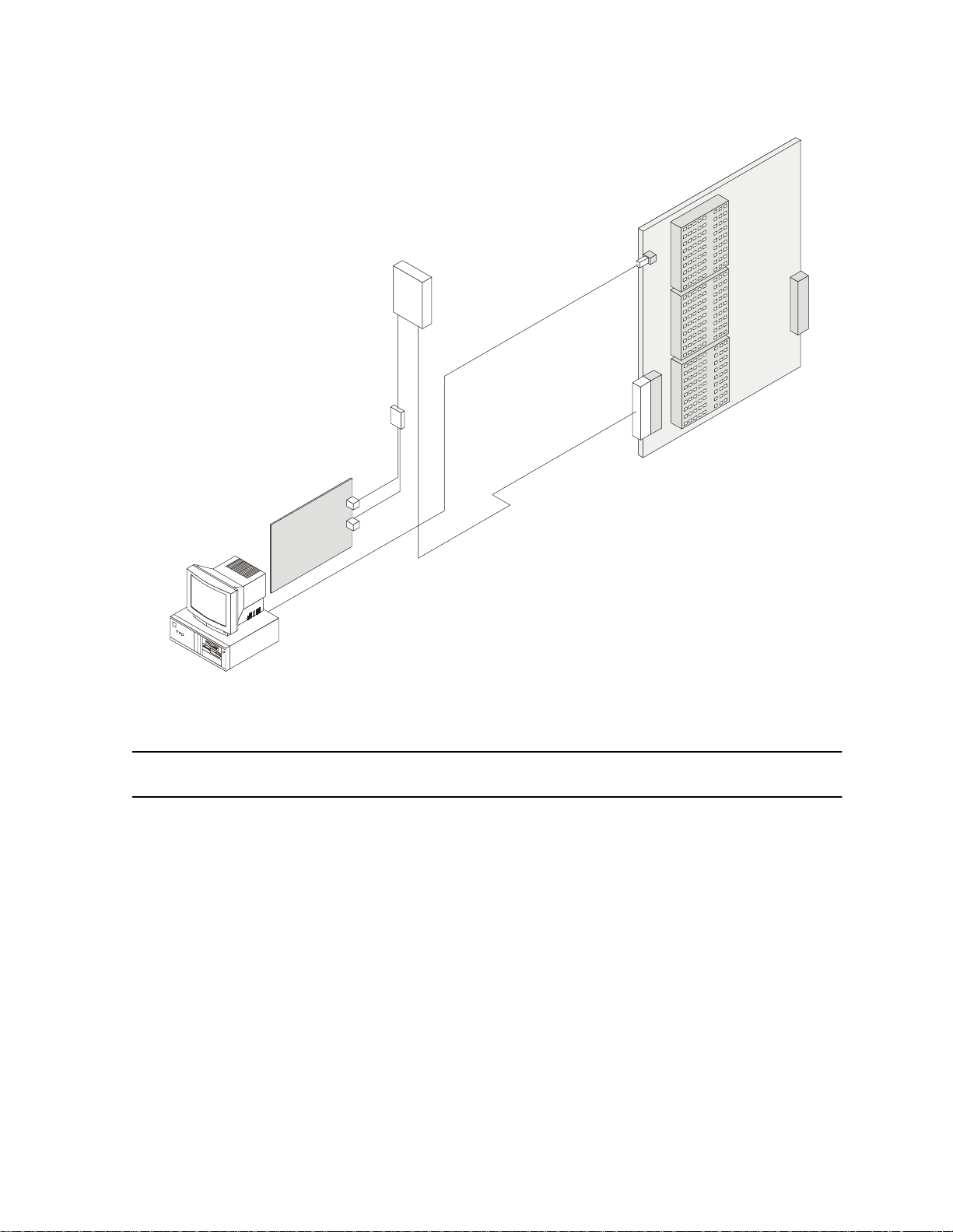
Audio cable/s from junction box to MDF
Junction box
Two two-pa ir audio c a bles from
PC card to junction box
Section 2: SYSTEM OVER VIEW
OC D card in system cabinet
Data cable from
PC to OCD card
MDF
Vo ic e mail c a r d
ins t a lle d in t h e P C
PC
2.4
e
maGEN
J1
J2
PC com port
Figure 2-1
e
maGEN
connections with the
Standard 25-pair cable/s from M DF
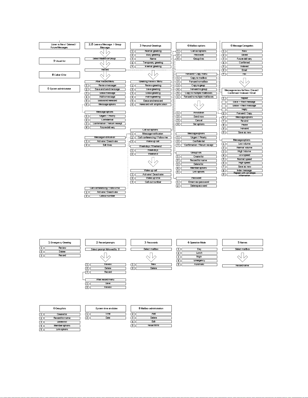
SYSTEM MENU FEATURE OVERVIEW
Figures 2-2 and 2-3, below, present overviews of
tion features and Adminis t ration features menu processing, r es pectively. Refer to these figures, as necessary, to follow the
processing flow and see the features involved.
Knowing the capabilities of each
taining the maximum amount of service and benefit to your organization. Many fe at ures have us er-define d p arameter s that you mu s t
program. This customized programming allows you to maximally tai-
e
lor
maGEN
to the specific needs of your organization.
e
maGEN
unite
system
e
maGEN
feature is the key to ob-
Opera-
e
maGEN
2-7
Page 25
76-110-0887/0, Issue 1
1/7/8
/LVWHQ WR 1HZ 'HOHWHG
)XWXUH 0HVVDJHV
9
9LVXDO OLVW
#
&DOOHU ,' OLVW
0
6\VWHP DGPLQLVWUDWRU
2/5
/HDYHD 0HVVDJH *URXS
0HVVDJH
6HOHFW 0DLOER[ RU *URXS
5HFRUG
$IWHU 5HFRUG0HQX
5HYLHZ PHVVDJHW
1
6DYH DQ G VHQG PHVVDJH
2
(UDVHPHVVDJH
3
$GG W R PHV VDJH
4
(UDVHDQG UHUHFRUG
5
0HVVDJHRSWLRQV
6
0HVVDJHRSWLRQV
8UJHQW 3ULRULW\
1
2
3
4
1
2
1
2
&RQILGHQWLDO
&RQILUPDWLRQ 5HWXUQ UHFHLSW
)XWXUH GHOLYHU\
0HVVDJHQRWLILFDWLRQ
$FWLYDWH 'HDFWLYDWH
(GLW OLQHV
&DOO FRQIHUHQFLQJ )ROORZ PH
$FWLYDWH 'HDFWLYDWH
&DOORXW QXPEHU
3
3HUVRQDO *UHHWLQJV
1RUPDO JUHHWLQJ
1
%XV\ JUHHWLQJ
2
3
4
5
1
2
3
4
5
6
1
2
3
1
2
1
2
3
1DPH
7HPSRUDU\ JUHHWLQJ
,QWHUQDO JUHHWLQJ
*UHHWLQJ 5HYLHZ 0HQX
5HYLHZ JUHHWLQJ
6DYH JUHHWLQJ
(UDVHJUHHWLQJ
$GGWR JUHHWLQJ
(UDVHDQG UHUHFRUG
5HUHFRUG ZLWK DPSO LILFDWLRQ
&DOO RXW RSWLRQV
0HVVDJHQRWLILFDWLRQ
&DOO FRQIHUHQFLQJ )ROORZ PH
:DNH XS FDOO
:HHNGD\ V :HH NHQ G
:HHNGD\ V
:HHNHQG
:DNH XS FDOO
$FWLYDWH 'HDFWLYDWH
:DNH XS WLPH
&DOORXW QXPEHU
4
0DLOER[ RSWLRQV
&DOO RXW RSWLRQV
1
2
6
1
2
3
4
5
6
1
2
3
4
1
2
3
1
2
3
4
5
1
2
3DVVZRUG
*URXS OLVWV
)RUZDUG &RS\ PHQX
&RS\WR PDLOER[
)RUZDUGWR PDLOER[
&RS\ WR JURXS
)RUZDUGWR JURXS
&RS\WR PXOWLSOH PDLOER[HV
)RUZDUGWR PXOWL SOH PDLOER[HV
$QQRWDWLRQ
6HQG QRZ
&DQFHO
6HW RSWLRQV
0HVVDJHRSWLRQV
8UJHQW 3ULRULW\
&RQILGHQWLDO
&RQILUPDWLRQ 5HWXUQ UHFHLSW
*URXS OLVWV
&UHDWH OLVW
5HFRUGOLVW QDPH
'HOHWHOLVW
0HPEHU RSWLRQV
/LQN RSWLRQV
3DVVZRUG
(QWHU Q HZ SDVVZRUG
'HOHWHSDVVZRUG
6
0HVVDJH&DWHJRULHV
1
2
3
4
5
6
7
0HVVDJHUHYLHZ IRU 1HZ 6DY HG
1
2
3
4
5
6
7
8
9
0
1
2
3
4
5
6
7
8
9
1HZ
6DYHG
)XWXUH GHOLYHU\
&RQILUPHG
,QGH[HG
(PDLO
)D[
&RQILUPHG ,QGH[HG (PDLO
5HSHDW
6DYH ! 1H[W PHVVDJH
(UDVH! 1H[W PHVVDJH
5HSO\
)RUZDUG &RS\
0HVVDJHRSWLRQV
5HZLQG
3DXVH
)RUZDUG
6DYH DV QHZ
0HVVDJHRSWLRQV
/RZ YROXPH
1RUPDO YROXPH
+LJK 9ROXPH
/RZ VSHHG
1RUPDO VSHHG
+LJK VSHHG
6DYH DV QHZ
,QGH[ PHVVDJH
5HSHDWZLWK HQYHORS H
LQIRUPDWLRQ
1
2
3
1
2
3
4
5
1
(PHUJHQF\*UHHWLQJ
5HYLHZ
'HOHWH
5HFRUG
6
*URXSOLVWV
&UHDWH OLVW
5HFRUGOLVW QDPH
'HOHWHOLVW
0HPEHU RSWLRQV
/LQN RSWLRQV
Figure 2-2
2
5HFRUGSURPSWV
6HOHFWSURPSW IROORZHG E\
1
2
3
$IWHU UHFRUG PHQX
1
2
7
6\VWHP WLPH DQG GDWH
1
2
Figure 2-3
e
maGEN
#
5HYLHZ
'HOHWH
5HFRUG
6DYH
5HYLHZ
7LPH
'DWH
e
maGEN
Operation Menu feature overview
1
2
8
0DLOER[ DGPLQLVWUDWLRQ
2
3
4
5
3
3DVVZRUGV
6HOHFW PDLOER[
1HZ
'HOHWH
$GG
'HOHWH
(GLW
5HVHW 0 :,
4
2SHUDWLRQ 0RGH
1
2
3
4
5
'D\
/XQFK
1LJKW
(PHUJHQF\
$XWRPDWLF
Administration Menu feature overview
5
1DPHV
6HOHFW PDLOER[
5HFRUGQDPH
2-8
Page 26

3.1 GENERAL
Section 3
INSTALLATION
Sections 3.2 through Section 3.6, below, describe planning and
component requirements for the installation of the
tem, .
Section 3.7 through Sect ion 3.16, below, describe the procedure for
e
installing the physical components of
maGEN
e
maGEN
within the
e
sys-
ma-
GEN
-PC, and the connecti on s between the
e
unit
Section 3.17 through Section 3.21, below, describe post-installation
checkout and troubleshooting procedures for
system.
3.2 INSTALLATION PLANNING
e
unit
Your
you can install
tion manual for full details of the required installation procedure.
Due to pr otocol chang es ,
System Software Release SB7, DB7 or LB7 be operating in your
system.
e
The
• Hardware installation, as described in Sections 3.7 through Section 3.16, below;
system must be fully installed and operational before
e
maGEN
installation sequence is as follows:
maGEN
. See the
e
maGEN
e
maGEN
e
maGEN
e
unit
family of systems Installa -
requires that at least
-PC and t he
.
e
unit
• Software installation, as described in Section 5 and Section 6,
below;
• Post-installation checkout, as described in Section 3.17 through
Section 3.21, below;
e
maGEN
•
described in Section 5 through Section 19, below;
system programming and administration, as
3-1
Page 27

76-110-0887/0, Issue 1
•
tion 19, b elow, utilizing the
system programming for
e
unit
3.3 INSTALLATION PREPARATIONS
3.3.1 Reading the documentation
e
3.3.2
e
maGEN
Prior to setting up the
and familiarize yourself with its content and the system compo-
nents.
-PC printed circuit cards
e
maGEN
The
cards, depending on the number of
establish in your system.
There are three types of
half-sized, ISA compatible voice processing cards, manufactured by
Brooktrout Te chnology, to choose from, in order to set up your system, as follo ws:
-PC must be fitted with
unit
maGEN
e
maGEN
e
maGEN
e e
manager
system, read through this manual
e
e
maGEN
four telephony port, single slot,
, as described in Sec-
.
maGEN
printed circuit
ports you wish to
• Prelude Quartet card;
• V antage Volare card;
• RDSP 432 card.
The
e
maGEN
Cards are assigned identification numbers f rom 1 to 4 for port programming assignment purposes. Port assignment is done in
system programming, utilizing the
3.3. 3 OCD card pr e paration
e
maGEN
NOTE
In systems having more than one card, four
port expansion cards may be used, since
data supp ort is alre ady prov ided by the first
card. In a 16-port system, a minimum of two
data cards is required.
e
maGEN
-PC can thus have any even number configuration of
ports -- from 4 to 28 po rts.
e e
unit
can be con fi gur ed with up to 28 v oi ce mail po rts, in all
Manager
e
unit
.
3-2
unit
e
systems.
Page 28

The
unit
Section 3: INSTALLATION
e
system configuration must include at least one OCD
3.3.4
e
maGEN
e
card for use with
include:
• a second OCD card, if the
than 12
• a second and third OCD cards, if the
includes more than 24
Each OCD card must be equipped with an MIM for each group of
e
maGEN
four
MIMs can be installed on one card, a fourth module on a second
card is required fo r a more than 12-port voice mail system. For a
system of more than four ports you can, if you choose, take advantage of the Multiple Communication Ports feature and balance system load and improve system performance by placing MIMs on
different OC D ca rds .
voice mail ports definition
You deci de wh ich
ports. You can designate any legal DN (directory number), up to four
digits in length, as an
maGEN. unit
e
maGEN
ports to be connected to the card. Since only three
unit
e
system configuration must
e
maGEN
voice mail ports;
e
maGEN
e
DNs are to be designated for
e
maGEN
port. All selected ports must be
system includes more
e
maGEN
voice mail ports.
system
e
maGEN
e
both c onnected to and pr ogrammed in the
unit
3.4 OPTIMAL COMMUNICATION PORT PROVISIONING
3.4.1 General
e
maGEN
more than one RS232 communication port simultaneously. This feature allows, f or example, SMDR data to be se nt se parately fro m
other
viding faster response time. You can thus assign the SMDR feature
e
maGEN
to
If your
munication traffic which increases system load.
The baud rate for all system elements will be 9600 bps.
has the ability to communicate wit h the
e
maGEN
e
maGEN
messages, thus distributing system load and pro-
ports which are supported by additional OCD card(s).
system supports SMDR, SMDR also create s co m-
system.
e
unit
system via
3-3
Page 29

76-110-0887/0, Issue 1
In order t o assure p roper functioning of the
Speech Recognition feature, it is recommended that adequate memory be installed
e
in the
128 MB memory should be added to an
e
maGEN
MB, for every four additional voice ports
installed in the system -- when upgrading
from the initial four voice ports.
3.4.2 Communication requirements programming
The baud rate for all system elements must be programmed as
9600 bps.
maGEN
-PC with an initial memor y of 128
-PC.
3.5 CRITICAL DISTA NCES
NOTE
e
maGEN
The
unit
the
3.6 REQUIRED CABLES
3.6.1 Data cable(s) from the
You must connect the first
the first OCD card in the
Section 3.9.3, below. You may have two or more OCD cards in the
unit
cards in the
load. If so, y ou must connect the last
ond OCD card as well.
This connecti on is made by means of a 3-wi re d a ta cab le, termi-
nated by:
• A 9-pin D-type female connector on the
e
e
system, either because there are four or more
end of the cable;
-PC can be located up to 50 feet (15 meters) from
e
system cabinet.
maGEN
-PC to the OC D card(s)
e
maGEN
e
maGEN
e
unit
system, or you choose to balance system
card to the RJ45 connector of
system cabinet, as described fully in
e
e
maGEN
e
maGEN
-PC card to the sec-
maGEN
-PC com port
-PC
3-4
• An RJ45 connector on the OCD card end of the cable.
Page 30

Section 3: INSTALLATION
3.6.2 Audio cable(s) from the
You m us t c onnect eac h
means of two audio cables, as described below and more fully in
Section 3.9.4, below.
This connection is by means of:
• Two two-pair cables from the
• A pair of wires from each junction box terminal pair to
• A standard 25-pair cable from the MDF plugs into the
e
maGEN
-PC to the O C D car d (s)
e
maGEN
e
box.
the MDF audio terminals corresponding to each
voice channel.
25-pair connector on the OCD card.
3.7 HARDWARE INSTALLATION PROCESS
e
maGEN
normally comes configured wi th t he de sir ed numbe r of
-PC card to an OCD card by
maGEN
-PC card to the junction
e
maGEN
port
e
maGEN
need to perform card installation yourself.
Installing
dures:
• Installing the
GEN
• Programming the
• Connecting the
These three s teps are de scr ibe d mor e fully below.
e
•
Section 3.8.1 and Section 3.8.2, below, describe:
• setting the
• inserting the
•
unit
• defining th e series of
-PC car ds. However, there may be situ ations where you
e
maGEN
-PC;
maGEN
-PC card installation;
e
system preparation; Section 19, below, descri bes :
hardw are consists of th ree separate proce-
e
maGEN
e
maGEN
e
maGEN
e
maGEN
-PC voice mail car d(s) into the
e
unit
system;
e
-PC to the
-PC card jumpers on each card;
-PC card(s) into the
e
unit
DN extensions necessary for
unit
system.
e
maGEN
e
ma-
-PC
e
maGEN
card ports;
• mounting the requ ired nu m be r of MIMs , de dica te d to
operation, according to the number of
e
maGEN
3-5
Page 31

76-110-0887/0, Issue 1
e
maGEN
• inserting the OCD card(s), with MIM(s) mounted, in the
system cabinet.
, on one, two or three OCD cards;
unit
e
3.8 INSTALLING e
3.8.1
IN THE
e
maGEN
e
maGEN
voice mail card jumper settings
e
• Connection between
Section 3.9.3 and Se c tio n 3. 9.4, b elow, describe:
• making the data connections between:
-- the first and, if present, fourth or last,
and the OCD card(s) in the
• making the audio connection between:
e
-- each
-- and the OCD block in the
junction box.
maGEN
maGEN
VOICE MAIL CARDS
maGEN
card in the
and the
e
unit
e
maGEN
e
unit
system cabinet;
syst em MDF, via th e aud io
unit
e
maGEN
-PC
e
system;
-PC card --
-PC
e
One or more of the following three types of
phony port , s ingle slot , half-sized, ISA com patible voice pr o c e ssing
cards, manufactured by Brooktrout T echnology, are used, in order to
set up your system.
maGEN
-PC four tele-
Depending on which of these cards are to be used in your system,
refer to the corresponding Brooktrout Technology Hardware installation Guide brochure:
• Pr elude Quartet car d -- Part N um ber 934-011-40, Rev ision 1.00;
• Vantage Volare card -- Part Number 934-009-90, Revision 1.00;
• RDSP 432 card -- Part Number 73-00-0014, Revision 1.00.
You should comply with all instructions in the brochure b efore inser t-
e
ing the respective type of
PC.
The Quartet board has fix ed settings as card no. 1, for which no
juper setting is required. For junper settings of all other cards, follow
the required jumper settings shown in Table 3-1, below, for each of
the respective cards. In this table: O = open circuit X = closed circuit.
maGEN
-PC card into the
e
maGEN
-
3-6
Page 32

Section 3: INSTALLATION
Table 3-1 I/O port jumper settings
Card
no.
3.8.2
MSB jumpers LSB
9876543210
1 OOXXXXXXXX
2 OOXXXXXXXO
3 OOXXXXXXOX
4 OOXXXXXXOO
5 OOXXXXXOXX
6 OOXXXXXOOO
7 OOXXXXXOXX
e
maGEN
-PC voice mail card insertion
e
You must insert the
Cards can be placed in any PCI slot.
Turn off and disconnect power to the PC,
before starting any card insertion procedure.
maGEN
-PC cards into the
WARNING
e
maGEN
-PC.
The physical act of installation is the same as for any other PC card.
This procedure is not described here, since it may vary from one PC
model to another. Refer to your PC manua l for card inst allation
instructions.
CAUTION
e
The
contain components that are sensitive to
static ele ctricity and sh ould not be ha ndled
except as needed to avoid any problem
with electrostatic discharge. Hold the card
by its outer edges. The use of a wrist
ground stra p is recom m ended , as sho wn in
Figure 3-1, below.
maGEN
-PC printed circuit cards
3-7
Page 33

76-110-0887/0, Issue 1
Strap
Desk for ground
Buckle
Figure 3-1 Wrist strap guarding against electrostatic discharge
Belt
3.9 SYSTEM PREPARATION AND CONNECTIONS
TO e
3.9.1 Mounting an MIM on an OCD card
maGEN
Figure 3-2, below, shows the three module positions on the OCD
card. Each OCD card can acc o mmodate up to th r ee cartrid ge modules, each serving a special option function.
You must c onnect one MIM (m ultiple interface modul e) on the OCD
card f or each group of f our
card. The MIM connects the voice channels to the
e
maGEN
An
one OCD card. However, a 16 port voice mail system requires four
MIMs, which necessitates two OCD cards. For a system of between
five and 12 ports you can, if you choose, take advantage o f the Mul tiple Communication Ports feature and balance system load (especially if the system includes SMDR) and improve system
performance by pla c i ng MIMs on two different OCD card s , as
described in Section 3.9.3, below.
You can select any positions on the OCD cards for the MIMs. If you
requ ire tw o OCD cards , fo r ex amp le, yo u ca n put t wo MI Ms o n ea ch
card; or you could put three MIMs on one card and the fourth on the
second.
1. Y ou must appropriately program the
in configuration programming covered in Section 19, below, to
match the selected MIM position(s).
system of up to 12 voice mail ports can be han dled by
e
maGEN
ports to be connec te d t o t he
e
unit
maGEN
e
system, as described
-PC.
3-8
Page 34

Section 3: INSTALLATION
e
2. You then assign voice channel and DN numbers to the
GEN
ports.
e
3. Lastly, you physically connect
audio cable, junction box, and MDF, to the audio channels of the
OCD card MIM(s).
To mount the MIM on the OCD card, perform the following steps, as
shown in Figure 3-2, below:
1. Place the OCD card on a soft, clean surface (a piece of sponge
or cardboard) with the components facing up.
2. Select the position in which the MIM is to be attached to the
OCD card:
• 3, the upper position, with 20 and 64-pin connectors
J6 and J9, respectively;
• 2, the middle pos it ion, with 20 and 64-pin connector s
J5 and J8, respectively;
• 1, the lower position, with 20 and 64-pin connectors
J4 and J7, respectively.
maGEN
-PC cards, via the
ma-
3. Plug the MIM into the selected pair of 20 and 64-pin connectors.
4. Make sure the module is seated firmly against the OC D car d.
5. Tighten the screw on the top of the module.
NOTE
The position in which the MIM is assigned
and moun ted on the O CD card determ ines
which vo ice channels an d which wires will
be dedicated to it for connection between
e
maGEN
the
cabinet.
-PC and the
unit
e
system
3-9
Page 35

76-110-0887/0, Issue 1
Figure 3-2 Inserting the MIM on the OCD card
3.9.2 Inse rt ing an OCD card into the s ystem ca bin et
To insert an OCD card in one of the
perform the following steps, as shown in Figure 3-3, below:
1. With the two plastic extension tabs on the end of the OCD card
extend ed outwa rds , slide th e card int o the gui de runn er s of the
selected slot.
2. Carefully fit the card into the V-shaped insertion guides.
3. Ensure that the female connector on the card is aligned with its
male counterpart on the system cabinet backplane.
4. Place both thumbs on the plastic tabs and press the card firmly
into place.
5. Fold the tabs flat against the card until they snap into place.
Each OCD card is connected to the MDF by means of a 25-pair
cable. This cable is standard for all cards in the
e
described in the
unit
family of systems Installation manual.
unit
e
system cabinet slots,
e
unit
system, as
3-10
Page 36

Figure 3-3 OCD card insertion
3.9.3 Completing the data connection
Section 3: INSTALLATION
The first
described below, directly to the OCD card in the
inet , by mea ns of th e RJ 45 c onn ect or loc at ed at t he end of the OCD
card. If two, or more,
only the first
four, o r more,
the fourth, or last,
If you choose, for a system of between five and 28 ports, as
described earlier, to take advantage of the Multiple Communication
Ports feature by placing MIMs on two different OC D car ds, there
must be a data cable connection between the last
card and the second OCD card as well.
e
maGEN
e
If your system has two, or more, OCD
cards, it is reco m m ended th at y ou also connect the second, or last, OCD card to the
e
maGEN
operating the SMDR features. This will
divide the communication load between the
e
maGEN
card in the
e
maGEN
e
maGEN
e
maGEN
-PC card assigned the ports
-PC and the two cards.
maGEN
-PC card, card number 1, to the OCD card. If
-PC cards are installed, you must connect
e
maGEN
-PC cards are installed, you connect
-PC card to the second OCD card.
NOTE
-PC conn ec t s , as
e
unit
system cab-
e
maGEN
-PC
3-11
Page 37

76-110-0887/0, Issue 1
e
maGEN
The
-PC card connection to the OCD card is by means of
a cable, shown in Figure 3-4 terminated by:
• A 9-pin D-type female connector on the
maGEN
-PC com port;
e
• An RJ45 male connector on the OCD card end of the cable.
RJ45 m ale cable connector - plugs into
RJ45 female connector on O CD card
With spring clip up - as shown cable wires are numbered 1 to 8, from left to rig
4 5
6
9-pin D -type fem ale cable connector
-- plugs into male PC com port
Figure 3-4 Data cable from
e
maGEN
The wire functions and connections for the
5
3
2
card to OCD card
e
maGEN
-PC card to
5
9
4
8
3
7
2
6
1
the OCD card data cable are shown in Table 3-1.
Table 3-2 Connections of data cable from emaGEN-PC card
to OCD card
9-pin D-type connector RJ45 connector
pin number function pin number function
2 transmit 6 receive
3 receive 5 transmit
5 ground 4 ground
3.9.4 Performing the audio connection
e
Each
unite
maGEN
system. It is connected to an OCD card, as shown in Figure 3-
5, below:
3-12
-PC card must have an audio connection to the
Page 38

Audio cable/s from junction box to MDF
Junction box
Two two-pair audio cables from
PC card to junction box
Section 3: INSTALLATION
OC D card in system cabinet
Data cable from
PC to OCD card
MDF
Vo ic e mai l ca r d
in th e PC
PC
Figure 3-5
J1
J2
PC com port
e
maGEN
Note in the Figure 3-5, that:
• Connector J3 on the
card containing the MIM by means of a cable, shown in Figure 3-
6, ter m inated by an RJ11 connecto r on both en d s .
Each of the terminal pairs in the junction box is connected, via a
pair of wires, as shown in Figure 3-6, to the audio terminals in the
MDF of the corresponding voice channel utilized as an
GEN
• A standard 25-pair cable, or cables, used to connect the OCD
block in the MDF to each OCD card in the
will then also make the final connection o f the corresponding
e
cabling from
port.
maGEN
ports.
Standard 25-pair cable/s from M D F
e
maGEN
e
maGEN
-PC to OCD card
-PC card connects to the OCD
e
unit
system cabinet,
e
ma-
This information should assist the installer in selecting the MDF ter-
e
minals to which each
to be wired.
maGEN
audio port from the junction box is
3-13
Page 39

76-110-0887/0, Issue 1
The wire functions and connections for the audio cable from the
e
maGEN
-PC card to a junction box, and from that junction box to
the MDF, are shown in Figure 3-6. For a detailed description of the
unit
e
system cabinet t o MDF connectio ns, refer to th e
unit
e
family
of systems Installation manual.
.
Four-pair wiring
-- one pair per port -to OCD block in MDF
1
Four audio port
junction box,
Avdor model
TA0666,
or equivalent
J1
RJ11 connectors to
e
maGEN-PC card
J2
2
3
4
1 2 3 4 1 2 3 4
1
2
3
4
1
2
3
4
Figure 3-6 Audio cable from
e
maGEN
1
2
3
4
-PC voice mail card
to four port junction box
Figure 3-7, below, shows the numbers and colors of each pin of the
25-pair cable connector from the OCD block in MDF to the OCD
e
unit
card in the
system cabinet, and each wire in this standard
cable which corresponds to the voice channels of each OCD card.
3-14
Page 40

Section 3: INSTALLATION
Figure 3-7 Typical 25- pair cable conne cto r from OCD block in MDF
3.10 ADDITIONAL STEPS BEFORE ACTIVATING
Although you have m ad e all the required physical connections
betw een the
ready to acti vate
steps:
e
maGEN
e
maGEN
-PC and t he
. You must now carry out the following
unite
e
maGEN
system, you are not yet
3-15
Page 41

76-110-0887/0, Issue 1
• Carry out the postinstallation checks described in Section 3.17 to
Section 3.19 of this manual.
• Program a series of
order for
instructio ns in S ec t ion 19 of this manual.
3.11 POWER CABLING
1. Before installing
lets for proper grounding and voltage.
• Be sure the third wire power ground connects to the building
unite
e
maGEN
Yo u should install an A C surg e protect or to
protect the
fluctuations. Install the surge protector
before setup and test procedures are carried out. Use of a UPS is also recommended.
input transformer or driven ground rod.
to operate, following the programming
e
maGEN
feat ures, which are ne c essary in
WARNING
e
maGEN
, inspe c t all wirin g and electr ical out-
-PC against power
• Voltage measurements between the black wire (measured
from the smaller of the two slots on an outlet) and third w ire
ground shou ld equa l 117VAC ± 10%.
2. In areas where electrical storms pose a danger, install a transient AC protection device in the power lines. This is particularly
important where power is provided by outside overhead lines.
Install a transient AC protect ion device if the system is installed
in a manufacturing area where motor driven machinery, compressors, pumps, elevators, or other periodically operating units
are installed.
3. Pr otect the equi pm ent against accu m ulated static electric ity
which can damage sensitive electronic circuitry in the cabinet. If
the site is at high altitude or in a dry climate, humidifying the
area may be neces s ary t o correct st atic electric it y problems.
3.12 MAIN DISTRIBUTION FRAME (MDF) CROSS CONNECTS
e
Connecting
individual single-line sets. The
wire modular line cords. Each jack on the telephone interface card
connects two ports (RJ-11 type connector).
maGEN
to a telephone system is similar to connecting
e
maGEN
system ports require two-
3-16
Page 42

Use modular line cords between the single-line set connections and
the ports, th en bund le and s ec u re the modular cor ds . Use a marker
to write the extension number assigned to the port number on the
modular cords.
Depending on the type of telephone system, and whether or not the
system is integrated, the method of connecting with the telephone
system varies. More information on integration may be found in the
PBX chapter.
3.13 PBX SOF TWARE CONSIDERATIONS
e
maGEN
ing and supports a hunt group comprised of extension numbers. The
class of service for
trunk access f or out dials, the ability to flash, and the ability to be a
target f or forwarded call s .
interfaces with any PBX software that allows call forward-
e
maGEN
Section 3: INSTALLATION
extension numbers should include
The pilot num ber of the hunt group cont ains as its members all the
exte ns ion n umb er s a ssi gn ed to the
dials the pilot number of the hunt group to access the system. A rotary or cir cular hun t group al lows the t elephone system to e venly di stribute calls to all
3.13.1 Setting up the PBX to accommodate
Before you start integrating
the following:
1. Set up enough analog ports for every port you have on
GEN
.
2. Program the analog extensions to accommodate voice mail.
3. Put the analog ports in a group. In most PBXs this group has to
be designated as a voice mail group.
4. Connect a single line phone or a test-set to each one of the analog ports and verify the fol low ing:
a. There is dial tone.
b. Call each extension and get a ring.
c. Call each extension, answer the call and receive touch-tones
when pressing keys on the calling extension.
e
maGEN
e
maGEN
e
maGEN
system ports.
e
maGEN
with the PBX, make sure of
system. A subscriber
e
ma-
d. Get in-band touch-tones in the beginning of the call (for
example when pressing the voice mail key on the calling
extension.)
3-17
Page 43

76-110-0887/0, Issue 1
3.14 INSTALLING THE
Use the following procedure to install the equipment:
1. Inspect the shipping cartons for signs of damage.
• The Carrier is responsible for any damage caused during
• Once the claim has been filed, the item or items will then be
2. Carefully open each carton and remove the content.
• Check the equipment against the packing slip to confirm that
• Notify the distributor and the shipper if any items are missing
• Carefully inspect each item for damage.
3. Remove the top cover off the chassis and verify that all cards
and cables are seated properly. Then close and secure the
chassis and place it in the selected location.
4. Connect the monitor and keyboard.
e
maGEN
shipm ent and should provide the distr ibutor with in f ormation
needed to file a damage report.
repaired or replaced.
all parts have been re c eived.
from the shipment.
SYSTEM
e
4. Be su re t he AC p owe r to
supply setting of the
5. Create the extensions in the telephone system database and
cross connect the MDF to an RJ-11 type connector block.
Assig n eq uipment numbers from at least two separate PBX line
cards. T his prevents total loss of voice message service in the
event of a single PBX l i ne card failure.
6. Locate the telephone interface ports on the back of the system.
• Use the 4 -w ire modular line cords to make the connections
between the telephone system and the ports.
• Four ports are on each telephone interface card with two
ports per jack.
7. Using a marker, write the extension numbers on each of the line
cords. Secure the cords and route them toward the connections
to the telephone system.
maGEN
e
maGEN
is compatible with the power
-PC. Plu g in th e p o wer cord .
3.15 QUICK STEPS FOR SOFT WARE INSTALLATION
3-18
1. Make sure the PBX system is configured to accommodate
GEN
.
e
ma-
Page 44

Section 3: INSTALLATION
2. Walk through Site Parameters and enter appropriate information.
3. Enter Port Definition and configure the lines as needed.
3.16 CHECKLIST
e
4. Walk through PBX Parameters and integrate
local PBX.
5. If there ar e several departments in the particular installation,
define them in Department definition.
6. Set the classes of service according to the customer’s needs.
7. Open mailboxes.
After completing the installation process, including the PBX section,
use the following check list to verify proper installation:
1. V erify the configur ation of the system against what was ordered.
e
maGEN
The
2. Create a test ma ilb ox .
3. Place a call to
4. Dial each port ind ividually (override the Hunt group ) and tes t the
following:
Monitor shows all active ports.
e
maGEN
and initialize the test mailbox.
maGEN
with the
a. Record and send a message to the test mailbox.
b. Review the message using all playback controls.
c. Check that each port disconnects properly.
d. Check transfer to operator by pressing 0 for an operator.
e
5. Ve rify PBX system forwarding to
sion that is forwarded to the system.
6. If the system is integrated, verify proper message waiting o p era tion by sending a message to a subscriber's mailbox with a set
telephone extensi on.
e
7. Dial the
access all the exten sions asso c iat ed with the hunt group.
8. Turn off the power to
e
maGEN
sure the time and date are correct
maGEN
reboots. Be sure the number of ports is correct. Be
pilot number and be sure the hunt group can
e
maGEN
maGEN
and turn it back on. Be sure
.
by dialing an exten-
3-19
Page 45

76-110-0887/0, Issue 1
3.17 CHECKING CABLING
After completing hardware installation, check all the wiring and
cables for integrity and sec ure conne c tio ns . Particular att ention
should be paid to the following items:
• The audio connections between:
e
• each
box;
• the audio junction box and the MDF.
• The data cabling between the
the OCD card.
• That all the connections to the
place.
maGEN
-PC voice mail card and the audio junction
3.18 CHECKING PRINTED CIRCUIT CARDS
e
maGEN
e
unit
-PC voice mail card and
system cabinet are firmly in
Check that:
e
• The OCD card(s) in the
MIM(s) dedicated to
seated in the correct slot(s) in the
defined in system programming;
• The MIM(s) dedicated to
the OCD c ard(s), as defined in
• The
• The jumpers on the
• The Application card, if present in the
e
maGEN
seated in its/their correct slot(s);
positions;
seated in its slot;
-PC card (s ) in th e
unit
e
maGEN
e
maGEN
system cabinet, on which the
is/are mounted, is/are firmly
e
unit
e
maGEN
unit
e
maGEN
-PC card(s) are set to the correct
system cabinet, as
is/are securely mounted on
e
system programming;
-PC is/are all firmly
e
maGEN
-PC-PC, is firmly
3.19 CHECKING SYSTEM CABINET TO MDF CONNECTIO NS
3-20
Chec k th at the cable con nectors from t he MDF to the OCD c ard(s)
in the system cabinet are secure at both ends.
Page 46

Section 3: INSTALLATION
3.20
3.20.1
e
maGEN
SYSTEM DETAILED
INSTALLATION INSTRUCTIONS
e
maGEN
V oic e Mail f ull insta lla ti on -- version 9
Comman ds you ne ed to type a re shown in
bold.
• Connect to the system with the followi ng FTP command
and
paste the installation file (t3install.tgz) to the directory.
• Connect to the system with the Telnet command
-- or locally with the terminal windows.
e
maGEN
•
• Password: tenecs
Last login:Sun Feb 3 15 : 10:40 from erez2000.telradnetorks.co.il
Have a lot of fun...
login: tenecs
NOTE
FTP://root:tenecs@[system_ip]
T e lne t [system_ip]
• tenecs@emagen: ~>su -
• Password: tenecs
• emagen: ~#ls
This command is like DIR to see if the installation file exists
(t3install.tgz).
. .Xauthority .gtk rc .netsc ape .xsession-er ror s
...bash_ his t ory . k de2 .skel Kdesk t op
.DCOPserver_emagen .exrc .kxmlrpcd .wmrc nsmail
.MCOP-random-seed .gnupg .mcoprc .xinitrc t3inst all.tgz
•emagen :~#tar -x z vf t3install.tgz
The system will create new a directory (t3install) and will extract
all files to this directory.
Wait until you get the command prompt before proceeding.
t3install.......
• emagen: ~#cd t3i n stall
• emagen: ~/t3install #./setup
• Install Suse Telnet
patches (Y/ N )?: y
Updating etc/rc.config...
• Install rhetorex (Y/N)?: y
Installing rh et orex files ...done
• Install
e
maGEN
system (Y/N)?:y
3-21
Page 47

76-110-0887/0, Issue 1
• Enter password for user t3adm.tenecs
• New pass w ord: tenecs
Bad password: too simple
• Re-enter new passw ord: tenecs
Password changed.
• Configure postgres
database (Y/N )? : y
• Import vmsys database (Y/N)?:y
• This will erase the old data. Are you sure (Y/N)?:y
• Import default registry (Y/N)?:y
• Install a1.exe file (Y/N)?: n
• Do you want to install other languages (Y/N)?:y
• Install Hebrew (Y/N)?: y
• Install extra stuff (Y/N)?: y
\jsdk/.......
• Install/Remove modem card.
1. Multitech ISICOM.
2. US Robotics 5610.
q. Finish with installation of modem card.
• >1
Driver loaded. Press enter to continue .
Install/Remove modem card.
1. Multitech ISICOM.
2. US Robotics 5610.
q. Finish with installation of modem card.
•>2
• Driver loaded. Press enter to cont in ue .
Install/Remove modem card.
1. Multitech ISICOM.
2. US Robotics 5610.
q. Finish with installation of modem card.
•>q
3-22
• Install hylafax
software(yes/no)? yes
Please wait ...Done.
Hylafax configuration.
1. Run fax setup.
Page 48

Section 3: INSTALLATION
2. Add a modem.
3. Remove a modem.
4. List availiable modems.
q. Finish with hylafax configuration.
• >1
Setup program for HylaFAX (tm)4.1.
No scheduler config file exists,creating one from scratch.
Country code [1]? [enter]
Area code []? 3
Long distance dialing
prefix [1]? [enter]
International dialing
prefix [011]? [enter]
Dial string rules file (relative
to /var/s p ool/ hy l a fax)
["etc/dialrules"]? [enter]
Tracing durin g no rmal
server operation [1]? [enter]
Default tracing dur ing send
and receive sessions
[0xffffffff]? [enter]
Continuation cover page
(relative to /var/spool/hylafax)[]?[enter]
Timeout when converting
PostScript documents
(secs)[180]? [enter]
Maximum number of
concurrent jobs to a
destination [1]? [enter]
Define a group
of modems []?[enter]
Time of day re strictions for
outbound jobs ["Any"]? [enter]
Pathname of destination
controls fi le (re lat iv e to
/var/spool/hylafax)[]?[enter]
Timeout before purging a
stale UUCP lock
file (secs)[30]? [enter]
Max number of page s to
permit in an outbound
job [0xffffffff]? [enter]
Syslog facility name for
ServerTracing messages
[daemon]? [enter]
The non-default s c heduler param eters are:
AreaCode: 3
3-23
Page 49

76-110-0887/0, Issue 1
• Ar e these ok [yes]? Yes
Creating new configuration file /var/spool/hylafax/etc/config...
• Hylafax co nf iguration .
1. Run fax setup.
2. Add a mode m .
3. Remove a modem.
4. List availiable modems.
q. Finish with hylafax configuration.
•>2
• Enter device (ttyXXX): ttyS3 (m odem in com4 de fine ttyS 1
for modem in com1)
Cou n try code [1]? [enter]
Area code [415]? [enter]
Phone number of fax
modem [+1.999.555.1212 ]? [enter]
Local identification string (for
TSI/CIG)["NothingSetup"]?[enter]
Long distance
dialing prefix [1]? [enter]
Inte rnational di aling
prefix [011]? [enter]
Dial string rules file (relative
to /var/spool/hylafax)
[etc/dialrules]? [enter]
Tracing durin g normal
server operation [1]? [enter]
Tracing during send and
receive sessions [11]? [enter]
Protection mode for
received facsimile [0600]? [enter]
Protection mode for
session logs [0600]? [enter]
Protection mode for
ttyS3 [06 0 0 ] ? [enter]
Rings to wait before
answering [1]? [enter]
Modem speaker
volume [off]? [enter]
Command line arguments
to getty program
["-t 60 %l % s"]? [enter]
Pathname of TSI access
control list file (relative to
/var/spool/hylafax)[""]?[enter]
Pathname of Caller-ID access
control list file (relative
3-24
Page 50

Section 3: INSTALLATION
to /var/s p ool/ hy l a fax)[ " " ] ? [enter]
Tag line font file (relative to
/var/spool/hylafax)
[etc/lutRS18.pcf]? [enter]
Tag line format string
["From %%l|%c|Page
%%P of %%T"]? [enter]
Time before purgi ng a stale
UUCP lock file (secs)[30]? [enter]
Hold UUCP lockfile during
inbo und data calls [ Yes]? [enter]
Hold UUCP lockfile during
inbo und voice calls [Y es ]? [enter]
Percent good lines to acce pt
during copy qual ity
checking [95]? [enter]
Max consecu ti ve b ad lines to
accept during copy
quality ch e cking [5]? [enter]
Max number of page s to
accept in a received
facsimile [25]? [enter]
Syslog facility name for Server
Tracing message s [ daemon]?[enter]
Set UID to 0 to
manipulate CLOCAL [""]?[enter]
Use available priority job
scheduling mechanism [""]?[enter]
You r facsim ile ph one nu m be r (+1.999.555.1212)does not agree
with your country code (1)or area code (415).
The number should be a fully qualified international dialing number of the form: +1 415 <local phone number>
Spaces,hyphens,and periods can be included for legibility.
For example, +1.415.555.1212 is a possible phone number
(using your country and area codes).
• The non-default server configuration parameters are:
CountryCode: 1
AreaCode: 415
FAXNumber: +1.999.555.1212
LongDistancePrefix: 1
InternationalPrefix: 011
DialStringRules: etc/dialrules
SessionTracing: 11
RingsBeforeAnswer: 1
SpeakerVolume: off
GettyArgs: "-t 60 %l %s"
Local Identifier: "NothingSetup"
TagLineFont: etc/lutRS18.pcf
TagLineForm at : "Fr om %%l|%c| Page %% P of
3-25
Page 51

76-110-0887/0, Issue 1
%%T"
MaxRecvPages: 25
• Ar e these ok [yes]? yes
• Hylafax co nf iguration .
1. Run fax setup.
2. Add a mode m .
3. Remove a modem.
4. List availiable modems.
q. Finish with hylafax configuration.
• >4
Modem List
ttyS3 [make sure you see the modem defined]
Press enter to continue. [enter]
• Hylafax co nf iguration .
1. Run fax setup.
2. Add a mode m .
3. Remove a modem.
4. List availiable modems.
q. Finish with hylafax configuration.
• >2
Enter device (ttyXXX): ttyM1a
Press [enter] for all options.
Are the s e ok [ y es]? yes
• Hylafax co nf iguration .
1. Run fax setup.
2. Add a mode m .
3. Remove a modem.
4. List availiable modems.
q. Finish with hylafax configuration.
• >2
Enter device (ttyXXX): ttyM1b
press [enter]for all options.
Are the s e ok [ y es]? Yes
3-26
• Hylafax co nf iguration .
1. Run fax setup.
2. Add a mode m .
3. Remove a modem.
Page 52

4. List availiable modems.
q. Finish with hylafax configuration.
• >2
Enter device (ttyXXX): ttyM1c
press [enter]for all options.
Are the s e ok [ y es]? Yes
• Hylafax co n figuration .
1. Run fax setup.
2. Add a modem.
3. Remove a modem.
4. List availiable modems.
q. Finish with hylafax configuration.
• >2
Enter device (ttyXXX): ttyM1d
press [enter]for all options.
Are the s e ok [ y es]? Yes
Section 3: INSTALLATION
• Hylafax co n figuration .
1. Run fax setup.
2. Add a modem.
3. Remove a modem.
4. List availiable modems.
q. Finish with hylafax configuration.
•>q
• Install Via Voice (Y/N)?: y
• emagen: ~/t3install #reboot
Broadcast message from root (pts/1)Sun Feb 3 16:19:59 2002...
The system is going down for reboot NOW !!
Broadcas t Messag e from root@em agen
(/dev/console) at 16:20 ...
Network is going down now!
3-27
Page 53

76-110-0887/0, Issue 1
3.21 INSTALLATION INSTRUCTIONS FOR ADDING ELEMENTS TO
THE
3.21. 1 How to ad d vo i ce ports
3.21.2 How to add fax ports
e
maGEN
SYSTEM
1. Run t3adm
2. Select x (extra stuff)
3. Select option 5 configure voice board
4. Follow instructions for adding voice boards
5. Replace the a1 file for support of more voice ports
6. Shut d own system
7. Add voice boards (make sure to strap the jumpers properly)
8. Start system
1. Power off the system and insert the fax board
2. Boot the syst em
3. Run t3adm
4. Make sure you have a1 license for fax
5. Select x (extra stuff)
6. Select option 3 configure fax
7. Select option 2 add modem
8. Follow instructions for adding modem.
Make sure to put in local fax number and fax name.
9. Reboot s y stem
3.21.3 How to add modem
1. Power off the system and insert the modem card.
Y ou can also use an ex ternal modem, wi thout turning the syst em
off.
2. Boot the syst em
3. Run t3adm
4. Select x (extra stuff)
5. Select option 2 define modem port
6. Select com port (for internal US Robotics use com 4).
3.21.4 How to add Unified messaging Push, POP, IMAP and applet
1. Make sure network parameters are working perfect (ping
another machine on the network).
3-28
2. Run t3adm
Page 54

Section 3: INSTALLATION
3. Select option 3 registry
4. Set parameters ->HostName to the IP address of the t3 system
5. Set smtp ->MailServer to the IP address of the SMTP server to
be used to send out
6. Set smtp ->Sender to an email address for the system administrator
7. Select option 1 Services
8. Select option 5 and set t3imap and t3pop to Automatic
9. R estart t3vm,t3pop,t3imap
10.Follow instructions in system manual to setting up e mail client to
a speci fic ma ilbo x
11. For Send Mail synchronization, follow the TTS instr uct ions - - if
you have TTS license.
If you do not have TTS license -- continue to line 12.
12.Run t3adm
13.Select option 1 Services
3.21. 5 How to ad d T T S
14.Select option 5 and set t3tts to Automatic
15.S elect opt i on 3 registry
16.Set tts ->smtpsync to 2
17.Restart t3tts
18.In Webcontroller ->Mailbox ->Email Set ti ngs ->
Need pe rm iss ion for Spee c h
19.In Webcontroller ->Mailbox ->Pop3Accout ns ->
put the ac co unts
1. Make sure you have license for TTS in a1 file
2. Run t3adm
3. Select option 1 Services
4. Select option 5 and set t3tts to Automatic
5. Restart t3 t ts
6. In Webcontroller ->Mailbox ->Email Set ti ngs ->
Need pe rm iss ion for Spee c h
7. In Webcontroller ->Mailbox ->Pop3Accout ns ->
put the ac co unts
3-29
Page 55

76-110-0887/0, Issue 1
3.21.6 How to add Speech Recognition
In order t o assure p roper functioning of the
Speech Recognition feature, it is recommended that adequate memory be installed
in the
128 MB memory should be added to an
e
maGEN
MB, for every four additional voice ports
installed in the system -- when upgrading
from the initial four voice ports.
1. Make sure you have ASR license for each voice port
2. Run t3adm
3. Select option 3 Registry
4. Set Parameters ->DirectoryAssist to Y
5. Restart t3vm service
NOTE
e
maGEN
-PC with an initial memor y of 128
-PC.
3.22
e
maGEN
SYSTEM DETAILED
BACKUP AND RESTORE INSTRUCTIONS
3.22.1 Back up option:
6. In Webcontroller ->Site ->Speech Recogntion ->
add all the names to be used in the d epartment
7. Using the administrator mailbox option 9 -- train the names
8. Define the names in Department -->Directory assist ance
9. Verify that all names exist in the Site ->Speech Recognition
table.
Press t he Verify List but t on.
10.P re ss the Ge ner ate SR file bu tton .
• Connect t o
User: tenecs
Password: tenecs
Last login:Thu Jan 31 18:59:36 from 141.226.213.60
Have a lot of fun...
e
maGEN
voice mail with Telnet.
Telnet [system_ip].
3-30
•Type: su-
password: tenecs
•Type: t3adm.
1. Start/Stop emaGEN Services.
Page 56

Section 3: INSTALLATION
2. Load tone file(s).
3. Change registry keys.
4. Basic ne t w ork configura tion.
5. System backup.
6. System monitor.
7. A1 Info.
8. Verify Installation.
9. Shutdown system.
x. Extra stuff.
• Select op tio n 5 for system backup.
This will backup your system.
e
Before that, it will stop any
Continue [yes/no]? yes
All files backup to /../usr/T3/backup.
maGEN
services.
3.22.2 Restore option:
******************Backup Completed ******************
e
• Connect t o
User: tenecs
Password: tenecs
Last login:Thu Jan 31 18:59:36 from 141.226.213.60
Have a lot of fun...
•Type:su-
• password: tenecs
•Type: cd /../usr/T3
•Type: cd backup (Togo to the ba ckup
directory).
•Type: ls (to see the list of files).
•Type DATE
This will show you the information about date and time of the last
backup.
•Type cd ..(to go back one directory).
maGEN
voice mail with Telnet.
T e lne t [system_ip]
•Type: cd bin (togo to the bin directory).
Type ./t3restore
Backup date:Thu Jan 31 19:27:13 PST 2002
This will erase all your DATA.
Are you sure [say 'yes']? yes
• You must reboot your system.
Press enter to reboot now.
3-31
Page 57

76-110-0887/0, Issue 1
NOTE
Restore will take affect from files under
/../usr/backup only. Do not change the
folder name or directory path.
******************Restore Completed ******************
3.23
e
maGEN
SYSTEM DETAILED
VERSION UPGRADE INSTRUCTIONS
3.23. 1 To view your current sys tem version.
1. Connect to the system with the Telnet command:
2. Type system login user name: tenecs
3. Type system login password: tenecs
4. Type the command SU -- to login as administrator.
5. Type the administrator password: tenecs
6. Type the command: T3adm
7. Choose option 8 -- to verify installation.
8. The system will show you its current version and will check the
installation [T3 10.1.8].
9. Press Enter -- to finish.
10.Press Q -- to quit to Linux shell.
3.23.2 Connect to the
e
maGEN
voice mail with FTP
telnet [system ip].
1. Connect to the system with the FTP command:
2. Copy the new ve rs ion to the
3. Close the FTP session.
3.23.3 Extract and upgrade
1. Return to the Telnet session .
2. Type the command ls
3. Type the command: tar xvzf [upgrade filename].
4. Type the command cd [upgrade directory name].
3-32
ftp://Root:tenecs@[system ip]
e
maGEN
the copy paste command.
If the T elnet session is closed, open it again, by following steps 1
through 5 in Sect ion 3.23.1, above.
[ls is like the dir command], you need to see the upgrade file you
transfer.
This will extract the installation file to the name directory.
voice mail folder, using
Page 58

to change to the installation directory file.
5. Type the command ./t3update
-- to upgrade the system version.
6. At the end of the upgrade
process type the command reboot
-- to reboot the system with new version.
7. Close the Telnet session.
3.23.4 Verify correct system version
After the system is up again, repeat the instructions in Section
3.23.1, above, to see i f t h e syste m v e rsi o n i s up dat e d an d if t h e
upgrade installation is verified as correct.
Section 3: INSTALLATION
3-33
Page 59

76-110-0887/0, Issue 1
THIS PAGE INTENTIONALLY BLANK
3-34
Page 60

4.1 GENERAL
Before the system actually begins processing calls, certain information must be entered to complete the installation. Information about
the company, the telephone system, and mailboxes must be entered.
4.2 CONVENTIONS
A command is always referred to by the chain of menus you need to select
to get to it. For example, to enter the mailbox menu: Users -> Mail boxes
Section 4
OPERATION
4.3 GENERAL RULES
There are a number of general rules of operation that apply no matter what
part of the system a subscriber or outside caller is using.
4.3.1 System Prompts
e
maGEN
prompts. These prompts outline a caller's choices at any given point or give
helpful explanations about the system.
As subscribers become more familiar with the system, they know which
keys to press without hearing the en tire prompt.
an experienced user to pr ess the correct key and interrupt the prompt.
It is possible to "key ahead", i.e., enter several commands very quickly without waiting for the system to respond with prompts. For example, when the
system first answers, subscribers enter #, their mailbox numbers and passwords to advance to the subscriber's menu.
4.3.2 No Response from the user
The system is designed to respond when any of the 12 keys on a Touch
Tone phone's keypad are pressed. If no key is pressed in response to a
prompt, the system assumes the us er is uncertain about the correct entry.
The system offers the caller assistance. If there is still no response, the system will pol itely disco nnect. This scenario will occ u r only af ter the s ystem
communicates with subscribers and o utside callers via
e
maGEN
system allows
4-1
Page 61

76-110-0887/0, Issue 1
has already detected DTM F durin g t he call, and it knows the caller has a
Touch Tone phone. In cases where DTMF is not detected by
the opening greeting point, when the caller does not respond to the
e
prompts,
specified in the Departments --> Properties --> No response mailbox
field.
maGEN
4.3.3 Too many Errors
The system counts the number of errors (incorrect key entries) that a user
makes while interacting with a menu. If the number of errors reaches the
pre-set number (usually 3), the caller is politely disconnected.
Errors are considered entries of invalid numbers such as extension numbers, passwords, date and time entries, etc.
4.3. 4 Allow ab le time betwee n key entries
There are a numerous places within the system where multidigit entries
must be made: mailbox numbers; group list numbers; phone numbers and
time entry.
e
maGEN
will transfer the call to the No response Operator,
at
The system is expecting a string of a pre determined digit length.
waits a few seconds between the digit entry, and upon receiving no
GEN
additional digits within the allowable time, it assumes that the entry was
complete.
For example, when e ntering mai lbox 123 as a destination, if there is too
long a pause between 2 and 3, the system
as 12 and not 123.
To define the l ength of time allowed between digit entries:
• use the System tim e out field, on the Site --> Settings screen, under
the System Parameters he ading.
e
maGEN
then responds based on the digits received.
4.3.5 Use of the # key to terminate an entry
The # key can be entered to terminate an entry. Though the system has
built-in timers that identify an end of a multi digit entry by a pre-determined
pause, a user can shorten the response time by pressing the # key, such as
when quickly entering a phone number.
4.3.6 Use of the * key
Cancel action: Many of the menu choices within the system include an option to cancel the user's selection by pressing the * key.
interpret the number entered
will
e
ma-
4-2
Move to previous menu: In all of the subscriber interface menus, pressing
the * key
result in returning to the previous menu.
will
Page 62

4.4 FIRST-TIME USER TUTORIAL
Section 4: OPERATION
Upon entering the mailbox as a subscriber for the first time,
greets the mailbox owner wi th a tutorial. The subscriber is prompted to
record a name, personal greeting and private password.
After having completed this t ut orial, the subsc riber:
• is now i n t he direc tory,
and
• hears the subscriber's m enu.
4.5 DIRECTORY TREE
e
•/usr/
e
•/usr/
e
•/usr/
e
•/usr/
e
•/usr/
e
•/usr/
maGEN
maGEN
maGEN
maGEN
maGEN
maGEN
/bin -- Ex e cutable files
/vox -- Voice files
/vmdat -- Data files
/mailbox/rpt -- Report files
/mailbox -- Mailbox greetings
/messages -- Incoming messages
e
maGEN
4-3
Page 63

76-110-0887/0, Issue 1
THIS PAGE INTENTIONALLY BLANK
4-4
Page 64

5.1 GENERAL
Section 5
SYSTEM ADMINISTRATION
e
maGEN
web based tools. You can connect t o the system through a direct
connect data cable, over an Intranet or the Internet, using a null modem cable or a standard modem.
There are several administration tools at your disposal:
e
•
network and start / stop the system.
cute d f rom teln et / Hy perTerminal.
e
•
voice mail ports.
system administration is done remotely using standard
maGEN
maGEN
T3adm – a configuration utility to help you setup the
e
maGEN
monitor – a display utility th at s how s t he status of the
T3adm is exe-
e
•
to
tion.
• standard ftp (file transfer protocol) – using standard ftp protocol,
you can access files on
gram.
This section will discuss the connection options as well as the
GEN
5.2 CONNECTING TO
5.2.1 Data Connection
The most efficient method to connect to
connection.
You can either connect:
• using a PC on the same network as
or
maGEN
e
maGEN
T3adm,
e
maGEN
WebController – a web based administration interface
, used to administer users, site an d PBX informa-
e
e
maGEN
maGEN
monitor and ftp connections.
with any browser or ftp pro-
e
ma-
e
maGEN
e
maGEN
is using a data
5-1
Page 65

76-110-0887/0, Issue 1
• create a direct PC-to-PC connection with a crossover data cable,
as shown on the right, in Fi gur e 5-1, below.
Figure 5-1 Crosso ver Cable Diagram
A data connection will ensure that TCP/IP protocol is running and will
enable ftp, web browsing and telnet.
For a data connection, you will need to know the IP address and sub-
e
net mask of
maGEN
.
5.2.2 Modem connection
e
Make sure a modem is connected or installed on
telephone line is connected to the modem. The modem is set to answer automatically by de fa ult.
e
You can network to it using windows dial-up networking.
To connect to an
account (as specified below) and then login to the system.
A. Connecting to a remote
1. Double click the dial-up account you create (as defined in the
2. Enter the user name and password of
3. Click “Dial”.
4. Enter the login name -- "tenecs", and press Enter.
maGEN
maGEN
two sections below)
"tenecs" by default.
A window should pop-up once a connection is established.
is c onfi gure d to a cce pt r emote admin istr ati on vi a mod em.
e
maGEN
is equipped with a built-in remote access mechanism.
e
maGEN
system, you wil l need t o crea te a di al up
e
maGEN
e
maGEN
-- both are
, and a
5-2
5. Enter the password -- "tenecs", and press Enter.
6. Once you have logged in, type slirp -P, and press Enter.
The system will print out its current ip address (default is
192.168.0 .100 ) , and o ther syste m information.
Page 66

Section 5: SYSTEM ADMINISTRATION
7. Click the “done” button (in Windows 98 click the “Continue” but-
ton), after which a new connection icon should appear in
the local machine's task bar, which means you have established
a TCP/IP connection with the remote machine.
8. Open an Internet browser, and enter in the URL line the remote
IP address (192.168.0.100) to see the Web Controller administrati on site.
B. Creating a dial-up account from windows 2000
1. Right-click “My Network Places”, se l ect “Properties” .
2. Double-click “Make new connection”.
3. Click “Next”.
4. Select “Dial up to private network” and press “Next”.
e
5. Enter
6. Indicate if the connection is for all user or for current user only
and click “Next”.
maGEN
modem number.
7. On the “internet connection sharing” page click Next.
8. Enter the connection name (e.g. “tenecs”) and press “Finish”.
9. Right- clic k the c onn ect io n you just cre ated (ins i de the “Net wo rk
and dial-up connections” window ).
10.Click the “Security” tab.
11. Select “Advanced” from the “Security options” and click on “Set-
tings”.
12.Select “Allow these protocols” and check all the specified proto-
cols.
13.Make sure the last check box, “For MS-CHA P…”, is not ch ecked
and click “OK”
14.Click “Yes” on the dialog box which then appears
15.In the “Security” tab, check “S how termi nal window” (a t the bot-
tom of the tab) and click “OK”
C. Creating a dial-up account from windows 98
1. Double-click “My Computer”.
2. Double-click “Dial-up networking”.
3. Double-click “Make new connection”.
4. Provide the connection name.
5. Select a mod em y ou want to con nec t w it h.
6. Click “Configure”.
7. Click the “Options” tab.
8. Check “B rin g up T ermi nal - Window afte r dialin g”.
5-3
Page 67

76-110-0887/0, Issue 1
9. Click “OK”.
10.Click “Next”.
11. Enter the
12.Click “Finish”.
5.2.3 Null-Modem connection
You ca n us e a null modem cable to connect to the communi cation
port on
dress, and you can us e it in case the IP c onnection is not functio nal
or th e I P address of
e
maGEN
e
maGEN
You will not be able to use the
WebController and ftp access to the system
using null- modem, as it is not an I P based
connection. However, you will be able to
run the
modem number.
. This connection will work regardless of an IP ad-
e
maGEN
e
maGEN
is unknown.
NOTE
e
T3adm pr ogram.
maGEN
5.3 ftp ACCESS
ftp (File transfer Protocol) is an internet standard for transferring files
between systems over IP protocol. In order to v iew the contents of
e
maGEN
need ftp access.
When connected to
work:
• open a browser window on your machine and type the following
in the address (URL) line of the browser:
where
e
For example, with the default address of
192.168.0.100, you will enter:
System as well as download or upload files to it, you will
e
ftp://root@
e
maGEN
maGEN
maGEN
e
maGEN
IPAddress is the nam e or IP a d dress of the
machine.
ftp://root@192.168.0.100/../usr/
using a crossover cable or over a net-
IPAddress/../usr/
e
maGEN
e
maGEN
e
maGEN
being
5-4
You will then be prompted to enter your administrator password.
e
Now you have access t o t he
past e and edit files by us ing standard Windows command s .
maGEN
directory and you can copy,
Page 68

Section 5: SYSTEM ADMINISTRATION
5.4
5.4.1 Logging in – “telnet”
e
maGEN
T3 Adm
The
able you to change IP configuration, start and stop
down the system and change low level
To run the
To run the
e
maGEN
To run telnet:
1. open a command prompt in windows and type:
e
maGEN
e
maGEN
e
maGEN
using telnet.
e
where
e
maGEN
For example:
maGEN
machine.
T3adm is an administration and setup utility. It will en-
e
maGEN
e
maGEN
T3adm program, proceed as follows .
T3adm program you need to be logged on to
e
telnet
IPAddress is the name or IP address of the
maGEN
IPAddress
parameters.
, shut-
5.4.2
e
maGEN
A communication session will start and the Linux prompt for user
name and password will appear.
2. Enter the user name and password (this entry is case sensitive).
• The default user name is: T3adm
• The default password is: tenecs
Y ou will then be at the Linux command prompt.
Telnet can only be used over IP. If you do not have an IP connection
established, you can use HyperTerminal over a null modem cable or
a standard modem to connect to
T3adm.
To exit from telnet:
• type exit twice
or
• simply close the command line window.
T3adm options
• Start the
at the prompt.
You will be pro m pted to ente r the super use r pass word .
e
maGEN
telnet 192.168. 0.100
e
maGEN
T3adm pr ogra m by typ i ng
and run
e
maGEN
e
maGEN
T3adm
5-5
Page 69

76-110-0887/0, Issue 1
The default password is: tenecs
You are now logged in as a super user and ready to use
T3adm.
e
You will get the main administration menu:
istrator Program.
You will have the following options:
e
1. Start/Stop
2. Load tone file(s)
3. Change registry keys
4. Basic n et w ork configura tion
5. System backup
6. System monitor
7. A1 Info
8. Verif y Ins tallatio n
maGEN
Services
maGEN
Basic Admin-
e
maGEN
5.4.3 Services
9. Shutdown system
x. Extra stuff
q. Unix shell
e
At any time -- while in the
press Ctrl to exit to the Unix shell.
To delete a character, use the Delete key, instead of the Backspace
key.
e
Each of the
include:
e
maGEN
•
e
•
maGEN
e
•
maGEN
e
•
maGEN
maGEN
VM -- T he main vo ice proc e ssi ng se rver
IMAP -- The IMAP server
POP -- The Pop server
TTS -- The text to speech server
maGEN
components is called a service. The services
T3adm pr ogram -- you can
5-6
e
Select option 1 from the
options to start and sto p each of th e se serv ice s. You can use this
when you need to reset any of the servers.
maGEN
T3adm options and you will get
Page 70

Section 5: SYSTEM ADMINISTRATION
NOTE
It is recommended to wait approximately 15
seconds after stopping a service before
restarting it, to allow all the program components to s hut down.
Option number 5 will allow you to select the startup mode for each
server.
When using the
you can select Manual or automatic. The default setting is automatic,
which means the server will start to work upon startup of the system.
5.4.4 Network configuration -- option 4
You can use the
e
maGEN
erating system.
1. Select option 4 of the
the req uired network informatio n:
• The IP address for this machine
• The Network subnet mask
• The Host name – by which you want to refer to this machine
• The Gatew ay -- through which the syst em can rea c h the
without any need for in depth knowledge of the linux op-
Do not use DHCP (Dynamic Host Configuration Protocol).
public int ernet
e
maGEN
e
maGEN
VM main voice processing server, only,
T3adm to c onfigure the IP add r es s of
e
maGEN
NOTE
T3adm main menu an d pro vi de
• The Domain Name Server (DNS) which is used to resolve
internet addresses
2. After changing this information, execute the shut down procedure and reboot the machine, for the changes to take effect.
3. Make sure to note the changes to allow further access through
IP to this machine.
4. If you fail to connect after reboot using telnet, you can resort to
the Telnet method using a null-modem cable or a standard
modem.
5.4.5 System Backup -- option 5
To backup the system:
1. Select option 5 of the
This will copy all the system files to a backup location.
e
maGEN
T3adm menu.
5-7
Page 71

76-110-0887/0, Issue 1
Before backup, the system will notify you it is shutting down.
2. After the backup is complete, you will have to manually restart
the system services.
5.4.6 System Monitor -- option 6
The system monitor will show you a real time info snapshot of all the
system ports, as well as indication of the status of the serial link.
You can use this option to start and stop each one of the voice ports,
as wel l as per fo rm a “s of t” shu td own of the system, that is, wait unti l
all ports are free and then stop the service.
5.4.7 A1 Info -- option 7
With this option you can view all the licenses given to the machine,
including number of voice ports, fax ports, email clients, languages
and more.
5.4.8 Verify Installation -- option 8
Running this option will:
• show the sof twa re releas e you are run nin g;
• verify that the system you are working with has all the correct
files relative to its version;
• gi v e y ou an indic a tion whether the process was successful or
failed.
5.4.9 Shut down -- option 9
You have to execute a shut down procedure before turning the system o ff:
• Select option 9 from the
You will be pro mpt ed to eithe r reboot the syste m or to halt it.
Before you selec t eith er opt ion , the progra m will doub le verif y
your selec t ion and, only the n, it will e x ec ute a shut do w n in c luding turning the power off.
5.4. 10 Ex t r a stuff -- option 10
Under the Extra Stuff section you will find options to:
• define a modem,
• configure the fax op tion,
• configure voic e cards ,
• define a PBX,
• import/export data configuration,
• re c reate administ rator mail box,
• enable/dis a ble mod em call in supp or t,
• change time zone,
• set date and time.
e
maGEN
T3adm m ain menu.
5-8
Page 72

5.4.11 Import/Export Data Base
You can import or export a mailbox, class of s erv ic e or depart m ent
data base. You can then upload this information on a different machine and put it back on the current system.
• Select the desired mailbox, COS or department.
The system will request a floppy disk,
or
it will save it in a temporary location.
5.4.12 Select PBX
e
maGEN
1. Simply select the PBX type
and
2. Restart
The values for the PBX you selected will appear on the PBX
page of the Controller.
Section 5: SYSTEM ADMINISTRATION
has a built in library of PBXs from which you can choose.
e
maGEN
(software only , reboot is not necessary).
5.4.13 Configure vo ice card
To add or remove voice cards to/from the system, you will need to
use the configure voice card option from
you acc ess this option , you will def ine all voice boards in the system.
You will need to specify the following information:
1. the address of each card in the system.
2. If the information shown is incorrect, type no.
3. If you type d no, above, you will be able to set the following
e
maGEN
The first card (ports 1 through 4) is by default on address 300.
The next are 301, 302 etc.
Refer to the Brooktrout Hardware installation guide for more
inform ation on settin g up t he add r e ss jumpers on the card.
After entering the address of the ca rd, the system will show you
the card configuration:
• the firmware version
• number of voice channels on the card
• number of D SP’s.
parameters:
T3. Each time
• Type the number of the firmware you wish to select
-- either 1 or 2, below:
1. firmvp.std is used in US cards (Quartet, RDSP 432).
2. firmvp.van is used in European cards such as the
Volare E U4 and PC I card s from the Vantage family.
5-9
Page 73

76-110-0887/0, Issue 1
5.4.14 Define modem
5.4.15 Configure Fax
• Enter the number of voice channels on the car d.
• Enter the number of RDSP on the card (1 for every 4 ports).
4. Finally, confirm the information and repeat for each card.
5. Reboot the system after completion of this process.
1. Select which com port will be used for remote administration.
For Com1 press 1, Com2 press 2, etc.
2. Fax ports can be defined as remote administration ports when
setting up fax ports, below.
Select the configure fax option from the T3adm menu -- under Extra
stuff.
The Fax installation has two steps:
1. Run fax setup – following the steps on the screen to initialize the
fax en gine.
2. Add a modem – the system will ask for a d evice name.
• If you are using a US Robotics modem (single port modem),
the device is ttyS3.
• If you are using a multi port modem, the device names are:
no. name port
i. ttyM1a port 1
ii. ttyM1b port 2
iii. ttyM1c port 3
iv. t tyM 1d port 4
v. ttyM1e port 5
vi. ttyM1f port 6
vii. ttyM1g port 7
viii. ttyM1h port 8
3. Follow the instructions for adding a modem -press Enter -- to select the default entry for each field.
4. Select either:
• option 4 -- to view the available modems,
or
5-10
• option 3 -- to remove a modem.
Before exiting from the fax configur atio n, th e syste m will ask you if
you want to use the fax port as a port for remote access.
Page 74

You can choose to enable or disable fax ports for remote administration by modem.
5.4.16 Installing the Fax software
In case step 1 of the pr evio us se ctio n fail s, th at is you cannot run the
fax setup option, follow the following procedure:
1. Log in as su per user -- type: su -, followed by the root pass word.
2. Type: cd /
3. Type: ./setup.
This will run the
4. Press N on al l optio ns , until you reach the Insta ll Fax option.
Answer Y to the Install Fax option.
5. Select the fax card type you wish to use -- Multitech or US
Robotics.
The driver for this card will be installed.
6. After installing the driver, press q -- to quit the fax installation and
continue.
e
maGEN
install
e
maGEN
Section 5: SYSTEM ADMINISTRATION
Installation procedure.
5.5
e
maGEN
7. Answer yes to the instal l hylafax so ftware question.
This will install the fax engine, and might take up to five minutes.
After this stage, you will be able to add modems to the fax engine, as
described in the previous section.
MONITOR
e
maGEN
The
that allows you to view the activity of the
used remotely over a network or the Internet.
Monitor -- shown in Figure 5-2, below -- is a utility
e
maGEN
ports. It can be
Figure 5-2
e
maGEN
Monitor screen
5-11
Page 75

76-110-0887/0, Issue 1
You can run it while connected over an IP connection. Double click
e
maGEN
the
Enter the IP address of
You can start or stop a port by right clicking the port.
Monitor icon. You will be prompted for a host name.
e
maGEN
. You will see the status of all ports.
5.6
5.7
e
maGEN
e
maGEN
CONTROLLER
e
maGEN
The
below -- is the top of the pyramid of all administration configuration
and definit ion scr een s.
Figure 5-3
See a detailed guide to
6-2 of Section 6, below.
Controller Main Menu screen -- shown in Figure 5-3,
maGEN Controller
e
Main Menu
Web Controller
Reports
SMDR
e
maGEN
Controller Main Menu screen
e
maGEN
screens and instructions in Figure
SYSTEM MESSAGE DETAIL RECORDING (SMDR)
5.7.1 Accessing SM D R Repor ts
1. Log in to the
2. Click the SMDR link.
The SMDR Reports definition screen, shown in Figure 5-4,
below.
5.7. 2 Gener ating a report
To generate a report:
1. Fill in the fields relevant to your query.
2. Press the [Generate Report] button, at the bottom of the
screen.
The fields are compounded, so you can create a complex query
by filling in multiple fields.
5-12
e
maGEN
T3 administration web page.
Page 76

Section 5: SYSTEM ADMINISTRATION
Figure 5-4 SMDR Reports definition screen
5.7.3 Costing of calls
To view information regarding a particular extensiion:
• fill in the Extension number field.
To view information regarding a particular trunk:
• fill in the Trunk number field.
Cost per minute
To generate price information, enter:
• either the cost per minute
and/or
5-13
Page 77

76-110-0887/0, Issue 1
• the surcharge per call.
The cost per minute is calculated in one minute increments.
For example:
If the cost per minute is 15 cents
and the call dur ation is 45 second s,
the call cost is 15 cents.
If the call duration is 1 minute and 5 seconds,
the call cost is 30 cents.
Call cost
If you entered information in the cost per minute section, above,
you can select calls by cost according to the following criteria:
• Fill in only the from field -- to view calls equal or above a certain
cost.
• Fill in only the to field -- to view calls equal or below a certain
cost.
• Fill in both the to and from fields -- to view calls between a range
of number s .
Called number
Fill in the called number field -- to view calls c on t ain ing the given
number. The called number field refers both to:
• numbers dialed on outgoing calls
and
• caller ID numbers in incoming calls.
Period
Enter a valid range of dates – from a certain date/time to a certain
date/time.
By default, the end date is today’s date.
Sorting Calls
The full report will show all legs of a call. If you selected calls for a
particular extension or trunk, full report will show all calls that the
extension or trunk took part in plus all other legs of these calls.
5-14
The summary report will show only t he first leg of each call, or the
legs, that a particular extension or trunk took part in.
You can sort the summary report by fields.
A sample SMDR report is shown in Figure 5-5, below
Page 78

Section 5: SYSTEM ADMINISTRATION
Figure 5-5 Sample SMDR Report
5-15
Page 79

76-110-0887/0, Issue 1
THIS PAGE INTENTIONALLY BLANK
5-16
Page 80

e
maGEN
Section 6
WEB CONTROLLER
6.1 THE
e
maGEN
Figure 6-1
WEB CONTROLLER MAIN MENU SCREEN
e
maGEN
Web Controller Main Menu screen
6.2 THE
UTILITY
6.3 TO USE THE
e
maGEN
WEB CONTROLLER ADMINISTRATION
e
maGEN
The
e
maGEN
the
e
The
maGEN
it locally or remotely over a network.
e
maGEN
1. Open a browser
2. Type in the IP address of
Web Controller screen is the administration utility of
system.
Web Controller is TCP-IP web-based, so you can use
WEB CONTROLLER
e
maGEN
6-1
Page 81

76-110-0887/0, Issue 1
-- in the address line (URL) of your browser.
e
3. Log into the
with a valid administra tor mai lbo x :
• the default mailbo x is 100
• the password is 0000.
At the start of each session you may specify the session timeout (default is 15 min utes). The session time out is the amount of time the
connection to the
elapsed time since the last activity to the server (any time you press
the command buttons is considered an activity). If you try to make an
operation after the timeout has expired, the system will take you to a
login page.
e
net Explorer and Netscape browsers, with
Java Script Enabled. Other browsers may
not necessarily work as expected.
maGEN
e
maGEN
maGEN
Web Controller
server will be open. This tim e is t he
NOTE
was tested with Microsoft Inter-
6.4 NAVIGATING THE SYSTEM
e
maGEN
The
the familiar conventions.
controller is a web-based application, and uses all
One esse ntial rule to remember is:
The information is not saved into the data-
base, until you click the SAVE icon.
NOTE
6-2
Page 82

maGEN Con troller
e
Main Menu
Fig. 5-3 Sect. 5.6
Web Controller
Reports
SMDR
Section 6: emaGEN WEB CONTROLLER
Web Controller
Main Menu
Fig. 6-1 Sect. 6.1
Mailboxes
Departments
Class of Service
Site Parameters
PBX
SMDR
See
Fig. 5-4
Sect. 5.7
Fig. 17-1 Sect. 17.1
Full Reports Mailbox Usage Daily
Mailbox List Port Statistics
System Group List System Statistics
Mailbox Usage by Date Hourly System Statistics
Reports
Main Menu
Mailbox screens
Properties Create New Mailbox Conversion Table Message Notification Script
Fig. 11-1 Fig. 11-3 Fig. 11-4 Fig 11-5 Fig.
Sect. 11.1 Sect. 11.3 Sect. 11.7 Sect. 11.8 Sect. 14.2
14-1
Mailbox screens -- continued
Email Settings POP3 Accounts Email Reply Settings Forwarding Options Groups
Fig.11-6 Fig. 11-7 Fig. 11-8 Fig 11-9 Fig. 13-2
Sect. 11.9 Sect. 11.10 Sect. 11.11 Sect. 11.12 Sect. 13.1
Departme nt s cr eens
Properties Working Hours Directory Assistance
Fig. 10-1 Fig. 10-2 Fig. 10-3
Sect. 10.1 Sect. 10.4 Sect. 10.6
Site Parameter screens
General Settings CID Routing Fax Settings
Fig. 7-1 Fig. 7-2 Fig. 7-5 Fig . 18-1
Sect. 7.1 Sect. 7.3 Sect. 7.13 Sect. 18.2
Class of Service screen
Group Members
Fig. 13-3
Sect. 13.4
Class of Service
Fig.12-1
Sect. 12.1
Site Parameter screens -- continued
Holidays PA Settings Global Groups Speech Recognition
Fig. 7-4 Fig.7-3 Fig. 13-1 Fig. 10-4
Sect 7.12 Sec t. 7.11 Sect 13.1 Sect. 10.6, 10.7
PBX screens
Parame te rs Integ r ation Trunk Po r t D e fin i tion Ser i a l In tegratio n
Fig. 9-1 Fig. 9-2 Fig. 9-3 Fig 8-1 Fig. 9-4
Sect. 9. 1 Sect. 9.11 Sect. 9.13 Sect. 8.1 Sect. 9.14
Figure 6-2 Your guide to
e
maGEN
screens an d i n structions
6-3
Page 83

76-110-0887/0, Issue 1
THIS PAGE INTENTIONALLY BLANK
6-4
Page 84
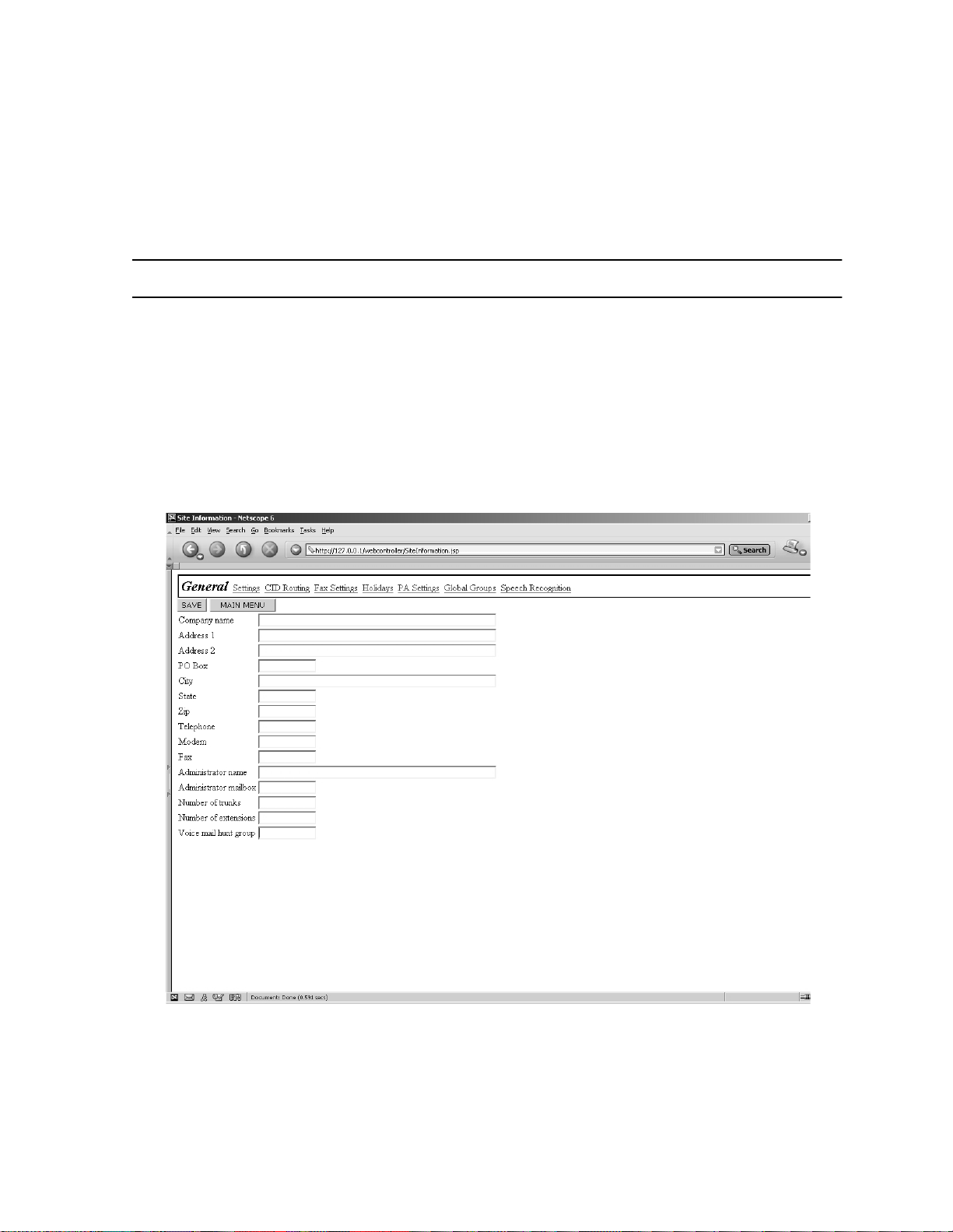
7.1 GENERAL
Section 7
SITE
e
To adapt a system to a specific site, meaning custo mizing
to the customer’s specific environment, you will need to configure
several sections of the system, including:
• Site Voice Mail Parameters -- included in this section
• PBX Port Definition -- see Section 8
• Department Definition -- see Section 10
maGEN
Figure 7-1 Site --> General screen
7-1
Page 85

76-110-0887/0, Issue 1
7.2 SITE – GENE RAL INFORMATION
Company Name
This is the name of the si te where the
Legal values:
Default:
Action:
Address
Thes e f ields are for the address of the installat ion site.
Legal values:
Default:
Action:
P.O. box
This field is where you can en ter a P.O. box if requ ire d.City
Legal values:
Default:
1 to 30 characters
Blank
Enter the name of the site.
1-30 characters, on 2lines
Blank
Enter the site address on the top line.
Use the second line for room numbers, etc.
1 to 6 digits
Blank
e
maGEN
system is in stall e d.
Action:
Legal values:
Default:
Action:
State
Legal values:
Default:
Action:
Zip code
Legal values:
Default:
Action:
Enter the P.O. box number
1 to 30 characters
Blank
Enter the name of the city
2 charac ters
Blank
Enter the two-letter state abbreviation.
5 or 9 digits
Blank
Enter the site location zip code.
7-2
Page 86

Section 7: SITE
Telephone Numbers
These fields are for the PBX/KTS system primary and secondary
phone nu mbe rs .
Legal values:
Default:
Action:
Fax number
This fi eld is where you can ente r the site's FAX number
Legal values:
Default:
Action:
Administrator Name
This space is for the
Legal values:
Default:
Action:
2 fields of 1 to 10 digits each
Blank
Enter the phone numbers, including area
code.
1 to 10 digits
Blank
Enter the site's FAX number.
e
maGEN
1 to 31 chara cte rs
Blank
Enter the System Administrator's name.
Administrator's name.
Administrator mailbox
This space is for the
tial to enter the mailbox number, in order for the administrator to be
able to use the remote access operations.
Legal values:
Default:
Action:
Number of Trunks
This entry is the number of Central Office trunks connected to the
PBX/KTS.
Legal values:
Default:
Action:
e
maGEN
A number -- up to seven digits long between
000000 0 and 99999999
Blank
Enter the System Administrator's mailbox
number
1 to 999
Blank
Enter the number of connected Central
Office trunks.
Administrator's mailbox. It is essen-
7-3
Page 87

76-110-0887/0, Issue 1
Number of Extensions
This is the number of extensions connected to the private telephone
system.
Legal values:
Default:
Action:
Voice Mail Hunt Group Extension Number
This is the pilot number of the hunt group that the PBX/KTS uses to
e
access
GEN
dial the number of the hunt group, in order to connect to the caller,
which is waiting on hold.
Legal values:
Default:
Action:
maGEN
announces the name of the subscri ber, and asks the person to
1 to 99999
Blank
Enter the number of connected extensions.
. This field is used for the paging feature.
1-7 dig its
Blank
Enter the hunt group pilot number.
e
ma-
7-4
Page 88

7.3 THE SITE SETTINGS SCREEN
Section 7: SITE
Figure 7-2 Site --> Settings screen
7.4 PARAMETERS ON THE SITE --> SETTINGS SCREEN
e
maGEN
dant detects a busy event from an extension, it can be set to allow
the caller to be placed on hold, in a queue.
incoming calls to this extension in a queue, and will let each caller
know their position in the queue. The system will try transferring the
caller to the extension after a defined period, while holding the call,
with full transfer supervision. If the extension is still busy, the system
will announce to the caller their position in the queue. While holding,
e
maGEN
to Chapter 16 – Voice Prom p ts) .
The following parameters needs to be set, on the Site --> Se ttings
screen, to activate this feature:
has a built-in call queuing feature. When the auto-atten-
e
maGEN
can play promotional announcements to the ca ller (refer
will arrange all
7-5
Page 89

76-110-0887/0, Issue 1
Maximum Ports on Hold Allowed
This fi el d d et erm ine s t he to ta l nu mbe r of port s in th e sy s tem tha t a r e
allowed to be placed on
amount is th e MAXIMUM regardl es s of the amount all owed in a
given mailbox.
e
maGEN
hold simultaneously. This
Legal values:
Default:
Action:
Time Interval Between Busy
This f ield controls t he timer t hat determ i nes how often
checks a held call to see if the called party's extension is still busy.
This time is used in conjunction with the next field.
Legal values:
Default:
Action:
This function is only valid for FULL transfer
supervision.
Max Ret r i es on Busy
This fi eld de ter mines the numbe r o f tim es t he ca lle r ca n be p romp ted
to remain in the queue, while the extension is busy. When this maximum is reached, the caller may no longer hold, rather the caller may
leave a message or be transferred to a different mailbox.
0 to 24
0
Select from the drop box.
5 to 999 seconds
20 seconds
Enter the duration between checks.
NOTE
e
maGEN
7-6
Legal values:
Default:
Action:
This function is only valid for FULL transfer
supervision.
1 to 99
1
e
Enter the desired number of t imes for
GEN
to check a busy extension before offering the held calle r an opp or tunit y to lea v e a
message or try another number.
NOTE
ma-
Page 90

Section 7: SITE
7.5 SPECIAL KEY PARAMETERS ON THE SITE --> SETTINGS
SCREEN
Directory Assistance Key
e
This field determines the digit that is pressed to have
present the directory of mailbox holders. Enter a space to disable the
directory assistance option.
maGEN
Legal values:
Default:
Action:
End Recording Key
This fi el d d et ermi ne s th e key pr es s
nal from the caller to end a recording.
Legal values:
Default:
Action:
Skip Backward- For ward
This field det ermines th e n u mber of seconds th at
skip backward (rewind) / or fast forward a message while the mailbox owner is listening to messages.
Legal values:
Default:
0, 1, 2 to 9, *, #
9
Select from the drop box.
e
maGEN
0, 1, 2 to 9, *, #, or @ (= any key)
@ (= any key)
Select from the drop box.
recogn i zes as the si g-
e
1 to 99 second s
3 seconds
maGEN
will
Action:
Pause
This field determines pause duration when pause key was pressed,
before playback resumes. Pressing any key while in Pause
resumes playback.
Legal values:
Default:
Action:
Enter the number of seconds for rewind/fast
forward.
1 to 999 seconds
10 seconds
Enter the number of seconds for pause dura-
tion.
7-7
Page 91

76-110-0887/0, Issue 1
7.6 SECURITY PARAMETERS ON THE SITE --> SETTINGS SCREEN
Administrator Password
This number is required for access to all System Administrator functions. The password can contain up to 4 digits.
Legal values:
Default:
Action:
Mailbox
This field te lls
numbe r. This val ue is us ed t o det erm in e if a c all er has dia l ed a mail box number or a conv e rsion ta ble dig it.
Legal values:
Default:
Action:
Extension Length
This field determines the
Legal values:
Default:
Action:
0000 to 9999
0000
Enter from 1 to 4 digits for a desired pass-
word
e
maGEN
1 – 7 digits
3
Select from the drop box.
1 – 7 digits
3
Select from the drop box.
how many digits make up a valid mailbox
e
maGEN
PBX ext ens io n num ber' s len gt h.
Password Length
This field determines how many digits are allowed for a mailbox user's password
Legal values:
Default:
Action:
.
1 to 9 digits
4
Select from the drop box.
7.7 GREETING HOURS PARAMETERS ON THE SITE --> SETTINGS
SCREEN
e
maGEN
depending on the time of day. This field determines what these time
7-8
announc es "Good Morning, Aftern oon, Eve ning"
Page 92

Section 7: SITE
periods are. There can occur a situation in which the time greeting is
“Good morning” yet the department greeting still indicates that the
office is closed (night mode - set in department definition) - e.g.
05:00 AM.
Legal values:
Default:
Action:
12:00 to 11:59 / AM / PM
Morning - 12:00 AM, Afternoon - 12:00 PM,
Evening - 05:0 0 PM
Select from the drop box.
7.8 HOUSEKEEPING PARAMETERS ON THE SITE --> SETTINGS
SCREEN
e
maGEN
sages, according to parameters defined in class of service.
Day
This field ent ry determines on which day t he house keeping will be
performed.
Legal values:
Default:
Action:
has a house keep ing mec h ani sm , which clea ns old mes -
Sun too Sat, Daily
Daily
Select day from the drop box.
Time
Enter th e ti me of day th e ho use ke epi ng ac ti vi ty i s t o b eg in. Th is ti me
should be at a no/low traffic period . Typically this is between midnight and 6 A.M .
Legal values:
Default:
Action:
Purge reports
Enter the number of months after which the system will delete old
report dat a.
Legal values:
Default:
Action:
HH: MM AM/PM
02:59 AM
Select ti me from the drop box.
number of months
2 months
Select ti me from the drop box.
7-9
Page 93

76-110-0887/0, Issue 1
7.9 SYSTEM PARAMETERS ON THE SI TE --> SETTINGS SCREEN
System Time Out
This is the duration of the time period after playing a system prompt
e
maGEN
that
tension. If no input i s receiv ed during this ti me per io d,
continues on to the relevant NO-RESPONSE action.
Recomm en ded du ratio n: 3 to 6 seconds.
gives the caller to key in the desired number of an ex-
e
maGEN
Legal values:
Default:
Action:
Script Time Out
Script: This is the duration of the time period after playing a script
menu t hat
extension. If no input is received during this time period,
continues on to the relevant ERR line for more actions.
Recomm en ded du ratio n: 6 seconds .
Legal values:
Default:
Action:
Conversion Table Time Out
This f ield sets the inter-digit ti me-out for th e conve r sion table. The
recommended time is 2000 msec. The entry should not be less than
800 msec.
e
1-12 seconds
4 seconds
Select duration from the drop box.
maGEN
gives the caller to key in the desired number or
1-12 seconds
5 seconds
Select duration from the drop box.
e
maGEN
7-10
Legal values:
Default:
Action:
Weekdays Definition
This fi el d d et ermi ne s wh at days
day. Any day not entered here will be considered to be Weekend
day.
Legal values:
Default:
200-40 00 ms ec
2000 msec
Enter the time-out period.
e
maGEN
Days of the week
Monday, Tuesday, Wednesday, Thursday,
Friday
is to consider as a Week-
Page 94

Section 7: SITE
Action:
Page Wait
This fiel d det ermi nes th e dura tion (in second s) of the paging feat ure.
This is the time a caller can wait on the line while
a subscriber. If the subscriber has not contacted the system within
this amount of time, the caller is prompted that the subscriber is not
available.
Legal values:
Default:
Action:
Check all days to b e con sidered w eekdays.
e
maGEN
1 to 9999 sec
Blank
Enter the desired time duration.
is paging
7.10 CALL OUT PARAMETERS ON THE SITE - -> SETTINGS SCREEN
e
When
messa ge no tifi cat ion, e tc., it dial s out on out si de tr unk ci rcui ts. Ther e
are two different results that
answered call.
maGEN
perfor ms a Cal l Out , s uch as wake -u p ca ll, remot e
e
maGEN
may rec eive other tha n an
Busy
This field controls the time interval between Call Out attempts for a
Busy condition .
Legal values:
Default:
Action:
No Answer
This field controls the time interval between Call Out attempts for a
No Answer condition.
Legal values:
Default:
Action:
1 to 999 m inu tes
3
Enter desired number of minutes to wait be-
fore retry.
1 to 999 m inu tes
30
Enter desired number of minutes to wait be-
fore retry.
7-11
Page 95

76-110-0887/0, Issue 1
7.11 PUBLIC ANNOUNCEMENT PARAMETERS
Figure 7-3 Site --> Public Announcement screen
e
maGEN
feature of the PBX. This allows the following
Firs t , if a mailbox ow ner is away fro m hi s /her phone, he/she can be
paged with in the loca tio n and receiv e their calls at a ph one else where in the building. Second,
make up to eight special pre recorded announcements to be played
back at specific times and days.
has the ability to activate the public announcement (PA)
e
maGEN
e
maGEN
can be programmed to
features:
Number
This is t he ID numbe r f or the availab le schedule assignments.
Legal values:
Default:
Action:
Prompt
This is the pr ompt number that you recor d for a s peci fic s chedu le announcement.
These prompts are hard-coded and may
not be changed.
Legal values:
Default:
Action:
1 to 8
1 to 8
None.
NOTE
See Action, below.
151 to 158
Record the appropria t e prompts using t he
"To Record A Prompt" option in the System
Administrator menu.
7-12
Page 96

Section 7: SITE
Day
This fiel d det ermine s th e day( s) on which a sch edule d PA an nounc ement w ill be made.
Legal values:
Default:
Action:
P.A. Time
This field sets the time for a scheduled announcement to be made
Legal values:
Default:
Action:
P.A. Zone
This determ ines the P. A. zo ne acces s code to whi ch an announcement is directed. The access code MUST match the desired PBX
paging access code.
Legal values:
Default:
Action:
Daily, None, Day of week
None
Select from the drop box.
HH: MM AM/PM
12:00 AM
Select ti me from the drop box.
0-9, *, or # / use "," for pause
Blank
Enter the page zone access code.
.
7.12 HOLIDAY SCHEDULE
Figure 7-4 Site --> Holiday Schedule screen
7-13
Page 97

76-110-0887/0, Issue 1
e
maGEN
their dates into the system. When the internal calendar matches one
of these dates, the appropriate holiday greeting will be broadcast to
the caller. The appropriate oper ation mode defined in the Holiday
Oper at ion M ode fi e ld i n De par tm ent De fi nit i on wil l b eco me a cti ve as
well. After the holiday message is played, the defined department
greetings will begin.
Holiday name
This is t he ID numbe r f or the availab le schedule assignments.
all ows you to pre- progra m up to 1 6 holi day mes sages an d
Legal values:
Default:
Action:
Date
This field determines the date of the related holiday.
Legal values:
Default:
Action:
Prompt
This is the prompt number to record for this particular holiday.
Legal values:
Default:
Action:
1-16 characters
None
None
MM/DD
00/00
Enter the desired month and day for this
schedule number or select a day from the selecti on calendar.
170-185
None
Record the appropria t e prompts using t he
"To Record A Prompt" option in the Administrator's menu.
7-14
Name
These are the names for the holidays.
Legal values:
Default:
Action:
1-20
None
Enter the holiday name.
Page 98

7.13 CID ROUTING
Section 7: SITE
Figure 7-5 Site --> CID Routing screen
The CID Routing table allows you to route calls based on the caller
ID information. You can use a complete number or a partial number
(which includes only the are a code, or area code + exchange) .
You can bind each number in this table with a specific mailbox (which
can also be a lead number for an ACD group or a script mailbox).
You can also specify the type of action to be taken with this number.
For example, you can define specific numbers to always be transferred to a mailbox to take a message, and other to be transferred to
a live extension.
To add new numbers to this list:
• Click the NEW button.
To remove numbers from the list:
1. Check t he REMOVE box.
2. C lick SAVE.
The CID routing table is used in conjunction with the Script opcode
CID Routing.
7-15
Page 99

76-110-0887/0, Issue 1
THIS PAGE INTENTIONALLY BLANK
7-16
Page 100

8.1 GENERAL
Section 8
PBX PORT DEFINITION
Figure 8-1 PBX --> Port Definition screen
The Po rt Definition menu define s the
the PBX --> Port Definition screen, as follows.
8.2 PORT PARAMETERS
Extension
This is the extension number to which the particular port is connected.
Legal values:
Default:
Action:
e
maGEN
1-7 dig its
Blank
Enter the related extension number
port parameters on
8-1
 Loading...