

Page 1
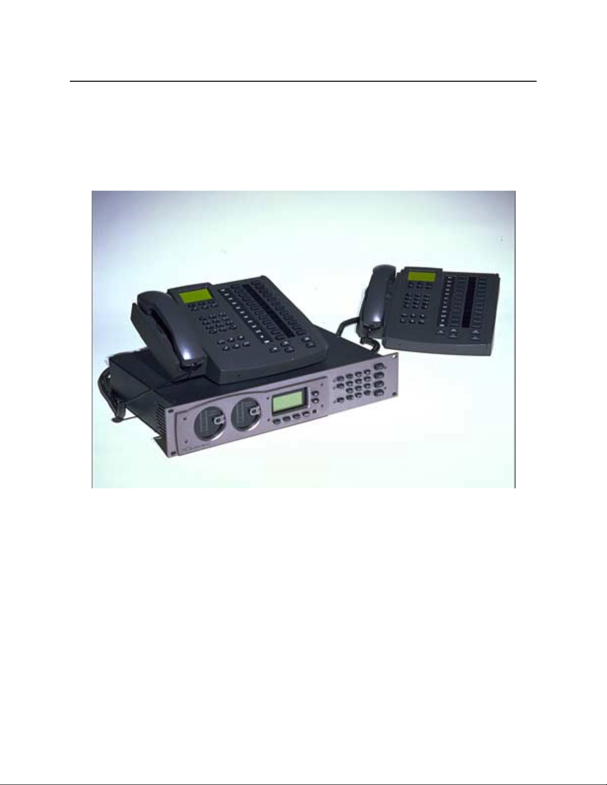
TELOS TWOx12
Advanced All Digital Dual Hybrid Multiline Broadcast Telephone System
USER’S MANUAL
Manual Version 1.0.1 for software version 1.0.1 and later
24 May, 2000
Page 2

Customer Service
We support you...
By phone/Fax in the USA.
Customer service is available from 9:30 AM to 6:00 PM USA Eastern Time, Monday through
Friday at +1 216.241.7225. We’re often here at times outside of these, as well – please feel
free to try at any time! Fax: +1 216.241.4103.
By phone/Fax in Europe.
Service is available from Telos Europe in Germany at +49 81 61 42 467.
Fax: +49 81 61 42 402.
By E-Mail.
The address is: [email protected].
Via World Wide Web.
The Telos Web site has a variety of information which may be useful for product selection.
The URL is: http://www.telos-systems.com.
Feedback
We welcome feedback on any aspect of the Telos TWOx12 or this manual. In the past, many
good ideas from users have made their way into software revisions or new products. Please
contact us with your comments.
Telos Systems
2101 Superior Avenue
Cleveland, OH 44114
USA
+1 (216) 241-7225
Fax: +1 (216) 241-4103
Telos Europe
Johannisstra ββββe 6
85354 Freising
Germany
+49 81 61 42 467
Fax: +49 81 61 42 402
II
Page 3

Updates
The operation of the Telos TWOx12 is determined almost entirely by software. A
continuous program of improvement is underway. Contact us to determine if a newer
release is more suitable to your needs.
Trademarks
Telos Systems, the Telos logo, TWO, TWOx12, and System 2101 are trademarks of
TLS Corporation. All other trademarks are the property of their respective holders.
Copyright
Copyright © 1994-2000 by TLS Corporation. Published by Telos Systems, who
reserves the right to make improvements or changes in the products described in this
manual, which may affect the product specifications, or to revise the manual without
notice. All rights reserved.
Notice
All versions, claims of compatibility, trademarks, etc. of hardware and software
products not made by Telos mentioned in this manual or accompanying material are
informational only. Telos Systems makes no endorsement of any particular product
for any purpose, nor claims any responsibility for operation or accuracy.
Warranty
Service
This product is covered by a one year limited warranty, the full text of which is
included in the section 10 of this manual.
You must contact Telos before returning any equipment for factory service. Telos
Systems will issue a Return Authorization number which must be written on the
exterior of your shipping container. Please do not include cables or accessories
unless specifically requested by the technical support engineer at Telos. Be sure to
adequately insure your shipment for its replacement value. Packages without proper
authorization may be refused. US customers please contact Telos technical support at
+1 (216) 241-7225. All other customers should contact your local representative to
make arrangements for service.
III
Page 4
Notices and Cautions
Notices and Cautions
Notices and CautionsNotices and Cautions
CAUTION:
THE INSTALLATION AND SERVICING INSTRUCTIONS IN THIS MANUAL ARE FOR USE BY
QUALIFIED PERSONNEL ONLY. TO AVOID ELECTRIC SHOCK, DO NOT PERFORM ANY
SERVICING OTHER THAN THAT CONTAINED IN THE OPERATING INSTRUCTIONS UNLESS
YOU ARE QUALIFIED TO DO SO. REFER ALL SERVICING TO QUALIFIED PERSONNEL.
e
WARNING:
TO REDUCE THE RISK OF ELECTRICAL SHOCK, DO NOT EXPOSE THIS PRODUCT
TO RAIN OR MOISTURE. DO NOT SHOWER WITH THE UNIT.
e
e
ee
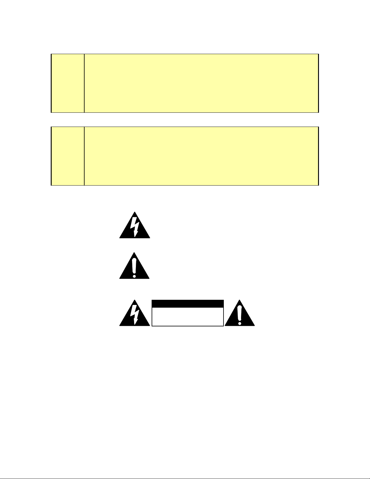
This symbol, wherever it appears, alerts you to the presence
of uninsulated, dangerous voltage inside the enclosure –
voltage which may be sufficient to constitute a risk of shock.
This symbol, wherever it appears, alerts you to important
operating and maintenance instructions. Read the manual.
TO PREVENT RISKS OF
ELECTRIC SHOCK,
DISCONNECT POWER
CORD BEFORE SERVICING
USA CLASS A COMPUTING DEVICE INFORMATION TO USER. WARNING:
equipment generates, uses, and can radiate radio-frequency energy. If it is not installed and
used as directed by this manual, it may cause interference to radio communication. This
equipment complies with the limits for a Class A computing device, as specified by FCC Rules,
Part 15, Subpart J, which are designed to provide reasonable protection against such
interference when this type of equipment is operated in a commercial environment. Operation of
this equipment in a residential area is likely to cause interference. If it does, the user will be
required to eliminate the interference at the user’s expense.
to TV or radio reception can occur if other devices are connected to this device without the use
of shielded interconnect cables. FCC rules require the use of only shielded cables.
NOTE:
Objectionable interference
This
IV
Page 5

CANADA WARNING: “
noise emissions set out in the Radio Interference Regulations of the Canadian Department of
Communications.” “Le present appareil numerique n’emet pas de bruits radioelectriques
depassant les limites applicables aux appareils numeriques (de les Class A) prescrites dans le
Reglement sur le brouillage radioelectrique edicte par le ministere des Communications du
Canada.”
This digital apparatus does not exceed the Class A limits for radio
V
Page 6

Table of Contents
Customer Service........................................................................................................................................................ ii
Conventions used in this manu al............................................................................................................................... xi
1 INTRODUCTION........................................................................................................1
1.1 System overview- What is this TWOx 12 Anyway?................................................................................ 1
1.2 Features and Benefits of the TWOx12 System........................................................................................ 1
1.3 Why ISDN Makes Sense for Broadcast Talk Show Systems................................................................ 2
2 INSTALLATION......................................................................................................7
2.1 Getting Started............................................................................................................................................. 7
System Configuration –........................................................................................................................ 8
Identifying your TWOx12 system – Analog or Digital?....................................................................9
2.2 Installation checklist (Copy this checklist and use it to help organize your installation)..11
2.3 ISDN Technology 101................................................................................................................................13
2.4 Ordering ISDN – an introduction...........................................................................................................14
2.5 Connections to the Telco circuits.............................................................................................................17
Introduction – Choices........................................................................................................................ 17
2.5.1 Connecting the Telos TW Ox12 t o ISD N).......................................................................................... 18
ISDN in USA & Canada: Using the U Interf ace............................................................................... 20
ISDN Worldwide (outside the USA & Canada): The S/T Interface............................................22
2.5.2 Integration with a PBX using ISDN................................................................................................... 24
2.5.3 Connecting the TWOx12 to POTS (Plain Old Telephone Service)...............................................25
2.5.4 Mixed ISDN/Analog Configurations.................................................................................................. 27
2.6 Studio Audio Connections........................................................................................................................ 30
2.6.1 Mix-Minus..............................................................................................................................................30
What is a mix-minus?......................................................................................................................... 30
Why do I need a mix-m inus?..............................................................................................................32
More on Mix-Minus............................................................................................................................32
Phones and Remotes........................................................................................................................... 34
2.6.2 Input- (To Caller ) Left & Right Analog Audio................................................................................. 35
2.6.3 POH (Program on Hold) Input...........................................................................................................36
2.6.4 Output – (Caller ) Left & Right Audio................................................................................................ 37
VI
Page 7

2.6.5 AES/EBU Digital Audio In/Out...........................................................................................................37
2.7 Desktop Director Connections.................................................................................................................38
Wiring Configurations for the Des ktop Director...............................................................................41
Multiple Desktop Directors on a single port...................................................................................... 42
Desktop Director Assembly................................................................................................................44
2.8 AC (mains) Power......................................................................................................................................45
2.9 Remote Control Ports................................................................................................................................46
2.9.1 Parallel Remote Control...................................................................................................................... 46
2.9.2 Special Auxiliary Access ports............................................................................................................ 49
2.9.3 RS-232 Serial Remote Control............................................................................................................49
2.9.4 Ethernet Remote Control..................................................................................................................... 51
3 GETTING UP & GOING –SYSTEM CONFIGURATION.....................................53
3.1 System programming ............................................................................................................................... 53
System Programming Check list......................................................................................................... 54
3.2 Initial Installation.......................................................................................................................................57
3.3 ISDN Setup (if you ordered an analog TWOx12 see section 3.4)............................................. 57
Worldwide ISDN Setup (outside USA & Canada):........................................................................ 58
USA & Canada ISDN Setup ........................................................................................................... 59
3.4 Analog phone line setup (If you ordered an ISDN TWOx12 see section 3.3)...........................62
3.5 Is the ISDN working?................................................................................................................................ 62
3.6 Levels, Levels, Levels.................................................................................................................................64
3.7 Time to test it out!......................................................................................................................................65
What now?...........................................................................................................................................67
4 DESKTOP DIRECTOR™- GENERAL OPERA TION.........................................69
4.1 General Description................................................................................................................................... 69
4.2 Status Symbol ™ Icons & What They Mean........................................................................................69
4.3 Buttons......................................................................................................................................................... 71
Line Control Button s...........................................................................................................................72
Telephone Mode Buttons....................................................................................................................73
User Function Buttons and LEDs –....................................................................................................74
4.4 Desktop Director LCD Screen & Menu Navigation Buttons..............................................................75
VII
Page 8

4.4.1 Menu Navigation...................................................................................................................................75
4.4.2 Changing from Producer to Talent mode..........................................................................................75
4.4.3 Volume Menus....................................................................................................................................... 76
5 TELOS DESKTOP DIRECTOR™ - GUIDE FOR CA LL SCREENERS.............79
5.1 General Description................................................................................................................................... 79
5.2 Status Symbol ™ Icons & What They Mean........................................................................................79
5.3 Buttons......................................................................................................................................................... 82
5.3.1 Line Control Buttons............................................................................................................................82
5.3.2 Telephone Mode Buttons ..................................................................................................................... 84
5.3.3 User Function Buttons and LEDs –.................................................................................................... 84
5.4 Desktop Director LCD Screen & Menu Navigation Buttons..............................................................84
5.4.1 Menu Navigation...................................................................................................................................85
5.4.2 Changing from Talent to Producer mode..........................................................................................85
5.4.3 Volume Menus....................................................................................................................................... 86
6 TELOS DESKTOP DIRECTOR™- GUIDE FOR TA LENT.................................89
6.1 Introduction to the Desktop Director..................................................................................................... 89
6.2 STATUS SYMBOL™ ICONS & WHAT THEY MEAN..................................................................90
6.3 DESKTOP DIRECTOR™ DISPLAY OPERATION- Talent Mode...............................................92
6.3.1 LCD display screen and menu navigation buttons............................................................................... 92
6.3.2 Volume Menus ...........................................................................................................................................93
6.4 DESKTOP DIRECTOR™ BUTTONS.................................................................................................94
6.4.1 Line buttons-...........................................................................................................................................94
6.4.2 PLACING CALLERS ON-AIR – Single caller................................................................................96
6.4.3 PLACING MULTIPLE CALLERS ON-AIR – Using lock mode................................................97
6.4.4 DROPPING CALLS OFF AIR.......................................................................................................... 98
6.5 USING AS A TELEPHONE....................................................................................................................98
VIII
Page 9

7 DETAILED CONFIGURATION & REFERENCE.................................................99
7.1 Level Metering ......................................................................................................................................... 101
7.2 Status Displays..........................................................................................................................................103
7.3 Advanced: Setting the TWOx12’s Configuration...............................................................................103
7.3.1 The Audio Menu..................................................................................................................................106
7.3.2 The Tel Menu......................................................................................................................................116
7.3.3 The System Menu................................................................................................................................122
7.4 Remote Control........................................................................................................................................127
7.4.1 RS-232 Control....................................................................................................................................127
7.4.2 Ethernet 10Base-T control.................................................................................................................137
7.5 System Audio Processing and Feedback Control...............................................................................138
7.5.1 Send Audio Processing........................................................................................................................138
7.5.2 Receive (Caller) Audio Processing....................................................................................................139
7.5.3 Duplex “Ducking” System.................................................................................................................141
7.5.4 Feedback Control................................................................................................................................141
8 TECHNICAL DATA AND TROUBLESHOOTING............................................143
8.1 Overview...................................................................................................................................................143
8.2 System Firmware..................................................................................................................................... 143
Viewing Version Information...........................................................................................................143
Replacing firmware...........................................................................................................................144
8.3 General Troubleshooting........................................................................................................................ 145
The Debug Status Screens................................................................................................................ 147
Using Loop Modes for Troubl eshoot ing ..........................................................................................148
8.4 Troubleshooting ISDN Problems..........................................................................................................148
8.5 Troubleshooting Desktop Director Problems......................................................................................152
8.6 Gaining Access ......................................................................................................................................... 152
8.7 ISDN Cause Phrases/Values...................................................................................................................154
9 SPECIFICATIONS..............................................................................................163
IX
Page 10

10 WARRANTY AND APPLICATION CAUTION..................................................165
11 APPENDICES.....................................................................................................167
11.1 Appendix 1 – Known Working SPID Formats by Telephone com pany.........................................167
11.2 Appendix 2 – Cable Guide......................................................................................................................169
Call Director to 2X12 Cable Pinout.................................................................................................171
Standard 10Base-T Ethernet Cable Pin out......................................................................................171
ISDN S Interface Cable Pinout.........................................................................................................172
11.3 Appendix 3 – Telephone Tech nology in the Di gital Age T utori al.................................................... 175
11.4 Appendix 4 - Glossary of useful ISDN and Telephone Terminology..............................................188
11.5 Appendix 5 - Suggested Reading...........................................................................................................200
ISDN..................................................................................................................................................201
Telephony..........................................................................................................................................201
Other..................................................................................................................................................201
11.6 Appendix 6 - ISDN BRI Ordering Guide for ETS 300 (E uro-ISDN).............................................. 202
Details, Details ..................................................................................................................................202
11.7 Appendix 7 - ISDN BRI Ordering Guide for USA & Canada.........................................................205
Ordering ISDN..................................................................................................................................205
Details, Details ..................................................................................................................................206
X
Page 11

Conventions used in this manual
The following symbols are used throughout this manual to highlight various type of
information contained within.
DANGER!
This information is important to safe operation of the equipment and warns of
possible hazards. For you safety you should read these.
e
IMPORTANT!
This information is essential to getting the TWOx12 to work, or prevent damage to it.
To avoid headaches read these.
w
h
i
c
HOT TIP!
This information will probably come in handy at some point. You will probably wish
to read these.
ISDN TIP!
Important information about ISDN. This is recommended reading for all ISDN users.
MIX- MINUS TIP!
Information useful when configuring your send- to- caller Mix- Minus feeds.
XI
Page 12

t
?
DEEP TECH NOTE!
Amaze your technical friends with your voluminous knowledge of the TWOX12,
ISDN, and hybrid technology! Not necessary for the ability to install and use the
TWOx12, but this information might come in handy if you ever need to troubleshoot
the system.
CURIOSITY NOTE!
Amaze your friends with your grasp of ISDN and Hybrid trivia. Not necessary for the
ability to install and operate the TWOx12.
XII
Page 13

TELOS TWOX12 USER’S MANUAL
1 INTRODUCTION
1.1 System overview- What is this TWOx12 Anyway?
The Telos TWOx12 is designed for small and medium market stations where up to
12 incoming talk lines are required. It is also well suited to dedicated studios within
larger facilities. Depending on the version ordered, the TWOx12 can utilize 6 ISDN
BRI circuits (with 2 channels or “Lines” per circuit) or 12 “POTS” (plain old
telephone service) analog lines, or certain mixtures of the two types. We recommend
ISDN BRI circuits whenever possible. Contrary to the perceptions of some, ISDN is
widely available and installation generally goes smoothly (this was not always true;
however our extensive experience with the Zephyr and ZephyrExpress codecs have
proven to us that this technology is mature). Follow the advice in this manual about
ordering ISDN and the process should go smoothly (see the Appendix for ISDN
Order forms).
For those who do not need the added quality available on ISDN, or cannot get ISDN
lines, we offer the POTS version for use on analog telephone lines. This version
offers the only available upgrade path from Analog to ISDN in any broadcast
telephone system today. You can get the flexibility of the system now. ISDN or
POTS, you can make the choice today without throwing away your investment
tomorrow- simply plug in new interface cards to upgrade from POTS to ISDN!
At the heart of any broadcast system are the hybrids used. Based on the Telos TWO
dual hybrid, the TWOx12 includes simply the best broadcast hybrids made. With a
trans-hybrid loss of well over 70dB (when used on digital lines) it allows for the best
possible announcer audio over the air. Performance when used with open speakers
and in teleconferencing applications is also superb.
The TWOx12 combines the TWO’s dual hybrid design with a twelve line system
controller and support for up to two (expandable to four) Telos Desktop Direc to r
control surfaces - typically one for a phone screener and one for talent. Each Desktop
Director can be easily reconfigured between the talent and producer (screener) modes
of operation. The Desktop Director has an intuitive user interface and we are
confident your staff will take to the system in no time.
If it sounds like we are proud of this system, you are right!
1.2
1.2 Features and Benefits of the TWOx12 System
1.21.2
Telos products have earned a reputation for ease of use and outstanding performance,
and the Telos TWOx12 lives up to that reputation. Our advanced ISDN hybrid
technology comprises an integrated suite of audio processing functions to achieve
unsurpassed audio quality.
!
Studio-grade 20-bit A-to-D conversion, combined with noise gating and shaping,
guarantees crystalline audio to the POTS lines and significantly improved send
levels.
!
Simultaneous analog and AES/EBU outputs.
CHAPTER 1 1
INTRODUCTION
Page 14

TELOS TWOX12 USER’S MANUAL
!
Automatic high-precision sample rate conversion for incoming ISDN circuits.
!
Unmatched Send/Receive sep ara ti on using Telos ’ ti me -te st ed Adap tiv e
Cancellation technology. Each hybrid automatically & continuously adjusts to
phone line conditions, virtually eliminating the hollowness, feedback and
distortion that occurs when send audio “leaks” into the caller output signal.
!
Sophisticated AGC/limiting functions and three-band Digital Dynamic
Equalization (DDEQ) ensure consistent caller audio levels and spectral
consistency.
!
Easy to use menus. Full metering for proper setup and operation.
!
Caller ID support and fully adjustable Caller Ducking (override) helps hosts stay
in control.
!
Conference linking ability lets you set up high-quality conferencing between
callers with no external equipment needed. (Only a single mix-minus is
required.)
!
Flexible system architecture allows you to buy an analog system now and
upgrade to ISDN in the future.
1.3 Why ISDN Makes Sense for Broadcast Talk Show Systems
ISDN is widely available, cost-effective, and offers many advantages for studio
systems. It is yet another example of digital technology enhancing broadcast
operations.
Integrated Services Digital Network (ISDN) is a set of international standards for
digital transmission over ordinary telephone copper wire (as well as over other
media). Presently, the dial-up telephone network is nearly entirely digital, except for
the “last mile” copper connections from the Central Office (Exchange) to the
customer’s site. Telos’ new ISDN hybrids take advantage of this technology to
deliver crystal clear caller audio to the radio studio.
Even though it takes two separate circuits — one send and one receive ci rcu it — to
transmit telephone audio, traditional analog lines multiplex both circuits in order to
use a single pair of wires. This causes what’s referred to as “leakage” – when the
announcer’s audio is present on the hybrid output, creating an annoying “hollow” or
“tinny” sound. A “four-wire” circuit has two wire pairs, and therefore two
independent audio paths. Digital circuits are designed to always offer independent
and separated signal paths. (Though a digital circuit may today not use wires at all,
but rather fiber, or microwave radio, or satellite, telephone engineers, bowing to
tradition, continue to refer to all separated speech paths as being “four-wire.”)
The telephone network routes calls over 64 kbps channels. A sampling rate of 8 kHz
is used, with a word length of 8 bits. The 8 kHz sampling rate supports a Nyquist
(audio cut-off) frequency of 4 kHz. In practice, telephone systems are designed to
have audio frequency response extending to 3.4 kHz in order to allow relatively
simple roll-off filters to be used.
CHAPTER 1 2
INTRODUCTION
Page 15
?
TELOS TWOX12 USER’S MANUAL
CURIOSITY NOTE!
The word length is what determines dynamic range–and 8 bits would only permit 48
dB were it used in standard PCM linear fashion. A primitive kind of compression is
used to stretch the dynamic range: µLaw in North America and much of Asia, and Alaw in Europe. This is a scheme that equalizes the step- size in dB terms across the
dynamic range–a smaller step- size on low- level signals reduces quantization noise
and improves effective dynamic range to the equivalent of about 13 bits. The Telos
TWOx12 automatically uses the appropriate method depending upon the ISDN
protocol setting.
While the application of digital signal process ing to the prob le m of separa ti ng host
and caller audio – pioneered by Telos and used in all of our telephone interfaces –
has made a dramatic improvement over pure analog syst e ms, usin g digital phone
lines for incoming calls further improves performance for several reasons:
ISDN Lines are I nhe rentl y “4 -wi re”
Analog lines use a single pair of wires for both signal directions, mixing the send and
caller audio. This causes the “leakage” problem–where the announcer’s audio is
present on the hybrid output, where we desire that there only be caller audio. A “4wire” circuit has two wire pairs, and therefore two independent audio paths. Digital
circuits inherently offer independent and separated signal paths because it is not
possible to have bits moving in both directions without separating them somehow.
(Though a digital circuit may today not use wires at all, but rather fiber, microwave
radio, or satellite, telephone engineers, bowing to tradition, continue to refer to all
separated speech paths as being “4-wire.”)
While the application of DSP to the problem of separating the signals–used in digital
hybrid interfaces–has made a dramatic improvement over analog systems, ISDN
enables yet further improved performance.
Better Digital-Analo g Conve rsion Qual ity
The analog-digital conversion chips used in telephone central offices are poor
compared to the converters used in professional audio equipment. Fidelity is not an
important consideration when most Telco equipment designers choose parts for this
function. In a professional interfa ce for stu dio appl ic at ions such as the TWOx12, we
can afford to design-in much better converters than available in the Telephone
Company’s equipment. Noise-shaping functions permit a larger word-length
converter to provide significantly better distortion and signal-to-noise performance.
Since we are handling the conversion, we can encode at higher levels without
concern about regulations designed to prevent crosstalk on analog lines, resulting in
improved send-to-caller levels.
In all-digital installati ons, the te lepho ne int erf ace can ma int ain a digita l path all the
way. AES/EBU is included in the hybrid to accomplish the connection to digital
studio gear.
CHAPTER 1 3
INTRODUCTION
Page 16
TELOS TWOX12 USER’S MANUAL
Lower Noise
Because they are digital circuits, ISDN lines are not susceptible to induced noise.
Analog lines are exposed to a variety of noise and impulse trouble-causers as they
move across town on poles and through your building. Hum is the main one, given
most line’s proximity to pole transformers and power lines, but there are also sources
of impulse noise from motors, switches, and other sources. Digital lines convey the
bits precisely and accurately from the network to your studio equipment without any
perturbation–so the audio remains clean. Even when the caller is using an analog
phone line to call in, the noticeably quieter digital connection between the hybrid and
the telephone network helps the hybrid achieve better rejection of outgoing audio
leakage.
Call Setup and S upe rvi sion are Bet te r
Analog lines use a strange mix of signaling to convey call status. Loop current drop
and returned dial-tone signal that a far-end caller has disconnected; blasts of 100
volts at 20 Hz mean someone wants you to answer. Why should we be using a
mechanism designed to bang a hammer against a metal bell to transmit network
status information into the 21
controlling calls and conveying status information about them. The sophisticated
transactions on the D channel are able to keep both ends of a call accurately informed
about what is happening.
For starters, ISDN call set-up times are often only a few 10’s of milli-seconds,
enhancing production of a fast-paced show. Perhaps more importantly, when a caller
disconnects while waiting on hold, the ISDN channel communicates this status
change instantly. This contrasts with the usual 11-second delay on most analog lines.
One of the most common complaints of talk hosts is that they go to a line where they
expect a caller to be waiting, only to be met with a blaring, annoying dial tone. The
chance of this happening with an ISDN line is nearly zero.
st
Century? ISDN uses a modern digital approach to
Another common error is the condition where a talent punches-up a line that looks
free, but which actually is just about to begin ringing and connects to a surprised
caller. This condition, called glare, results from the delay in the ring signaling, which
comes from the nature of the analog line’s ringing cadence. This is much less likely
with ISDN because it eliminates the ambiguous statu s period.
CURIOSITY NOTE!
We don’t know why the condition of picking up a line which was about to ring and
getting an incoming call instead of dial tone is called “Glare”. Perhaps its because the
looks air staff give engineers when this happens too often!
If you find out, be sure to let us know!
?
Higher Gain and Re du ced F eedb a ck Durin g M ulti - line C onfe ren ci ng
Higher Gain and Reduced Feedback During Multi-line Conferencing. When
conferencing is required on 2-wire circuits, very good hybrids are needed to separate
CHAPTER 1 4
INTRODUCTION
Page 17

TELOS TWOX12 USER’S MANUAL
the two audio paths in order to add gain in each direction. When the gain around the
loop exceeds unity, the unpleasant result is feedback. Since the conference path
usually includes four AGC functions, the hybrid must be sufficiently good to cover
the additional gain that may be dynamically inserted by these AGC’s.
Because of the 4-wire nature of digital telephone lines, the hybrid function is more
effective–and more reliably so across a variety of calls. That means more gain can be
inserted between calls before feedback becomes a problem.
Better Line Monit o ring , Call Setu p a nd Super vi sion .
Since there is a full-time connection between the central office and the terminal on
the D channel, it is possible to detect when a line is a not working. On an analog line,
one discovers a problem only from a failed attempt to use the line. Many digital
phone lines maintain a full-time connection between the Central Office and your
studio on the “D” channel, so you can quickly detect when a line is a not working.
Furthermore, the sophisticated transactions on the “D” channel keep both ends of a
call accurately informed about line status. For starters, digital lines feature call set-up
times of only a few milliseconds, enhancing production of a fast-paced show.
Perhaps more importantly, when a caller disconnects while waiting on hold, this
status change is communicated instantly (contrasted with the usual 11-second delay
on most analog lines). One of the most common complaints of talk hosts is that they
go to a line where they expect a caller to be waiting, only to be met with a blaring,
annoying dial tone. The chance of this happening with a digital line is near zero.
Elimination of A -to-D & D -to -A conv ersion s.
The analog-digital conversion equipment used in telephone central offices is of poor
quality compared to the converters used in professional audio equipment. Using a
digital phone line enables you to maintain a digit al path al l the way from the cal le r’s
central office to your studio equipment — requiring only the initial conversion to
digital, and doing away with the need to reconvert from digital to analog audio.
AES/EBU outputs are provided on TWOx12 Talk Show System to help accomplish
this direct connection to digital studio gear.
CHAPTER 1 5
INTRODUCTION
Page 18

TELOS TWOX12 USER’S MANUAL
This page intentionally left blank.
CHAPTER 1 6
INTRODUCTION
Page 19
2 INSTALLATION
2.1 Getting Started
In this chapter we will cover the various input/output connections of the TWOx12 and what
you need to know to install the system. We also give you a brief introduction to ISDN in
section 2.3 since some users may not be familiar with it. Later, in section 3, we will cover
the steps necessary to configure the unit for initial operation and test it. Section 7 has a
detailed reference of all menus.
The Telos TWOx12 mounts in a 2RU high space in a standard 19” rack. You do not need
to pay special attention to cooling or ventilation, as the unit will operate in any environment
where humans would be comfortable. The unit will operate on any commonly available AC
mains voltage between 90 and 240 volts 50 – 60 Hz. You will want to mount the unit in a
position convenient for cable access for the ISDN lines and audio connections.
Next, you will need to:
• *Order or confirm availability of appropriate ISDN BRI lines
• Connect the Telco circuits
TELOS TWOX12 USER’S MANUAL
w
• Connect audio, via either analog or digital AES/EBU
• Connect 1 or more Desktop Directors (control surfaces)
• Connect to power
• Connect to LAN (local area network), if Call Screen Manager 2.0 is to be used
• *Configure the TWOx12 to match your ISDN lines
• Configure the built in hybrids’ audio characteristics for the requirements of your
installation
• Test to confirm proper operation
* This step can be skipped if analog (POTS) tele phone lines are used.
IMPORTANT!
This manual goes into detail about ordering & using ISDN, and programming information
into the unit about your ISDN lines. If you purchased the POTS (analog) version of the
TWOx12 you can disregard that information.
CHAPTER 2 7
INSTALLATIO N
Page 20

Since ISDN will be new to many users, sections 2.3 & 2.4 give an introduction to the
technology. If you are using analog telephone lines (POTS) you can skip those sections if
you wish.
As you read through this chapter connect your inputs and outputs. In section 3 we will
proceed with detailed system configuration issues.
System Configuration –
A “maxed out” TWOx12 includes the following:
"
4 Desktop Call Directors
"
6 ISDN BRI circuits (with 2 callers per BRI circuit)
OR, depending on the version ordered,
"
12 POTS analog telephone circuits (loop start)
"
1 dual channel AES/EBU send-to-caller digital mix-minus source
OR
"
2 send-to-caller analog mix-minus source(s)
"
1 dual channel AES/EBU Caller output
AND/OR
"
2 Analog caller outputs
"
1 program on hold analog source
TELOS TWOX12 USER’S MANUAL
Note that there are several configuration choices that you will be making in order to install
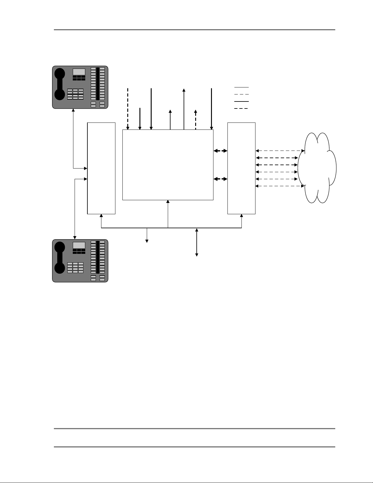
the system in a given facility. A diagram of the TWOx12’s inputs and outputs follows.
CHAPTER 2 8
INSTALLATIO N
Page 21
TELOS TWOX12 USER’S MANUAL
L
L
E
e
R
r
I
o
CONTRO
BLOCK
SEND
to Caller
(AES)
1&2
to Caller
(Analog)
SEND
to Caller
(Analog)
1
SEND
2
CALLER
Out
(Analog)
1
INTEGRA
TELOS
TWO
HYBRID
CALLER
Out
(Analog)
2
CALLE
Out
(AES)
1&2
Program
on Hold
Source
TELCO
INTERFAC
&
MATRIX
BLOCK
TWOx12 Telephone Interfac
KEY
Data
ISDN BR
Analog Audio
AES/EBU Audi
ISDN
(PSTN)
Ethernet 10 base-T WAN/LAN
Connection for Assistant Produce
and remote control
Parallel Outputs (Status &
Control) and Remote control
The input & output ports of the TWOx12 system.
Note that the system can easily be expanded to support up to four Desktop Directors™; Only one
of the input options (AES/EBU or Analog) can be selected at a given time; POTS TWOx12
systems substitute 12 analog POTS circuits for the ISDN circuits shown above.
Identifying your TWOx12 system – Analog or Digital?
You will need to identify whether your system is a POTS (Plain Old Telephone Service analog) or an ISDN version, since we will cover them separately in the following
instructions. If you are installing a mixed system you should read through both sets of
instructions. Towards the end of this section (section 2.5.4) we will specifically address
mixed POTS/ISDN systems.
CHAPTER 2 9
INSTALLATIO N
Page 22
TELOS TWOX12 USER’S MANUAL
Analog TWOx12 version
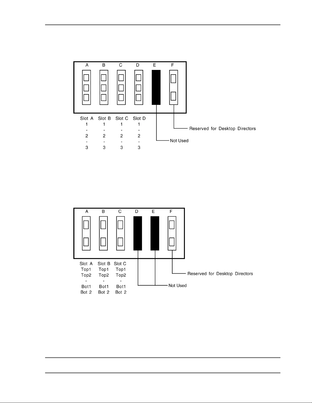
The Analog version of the TWOx12 has Telco interface cards in slots A, B, C, & D. Each interface
supports three analog telephone circuits using standard RJ-11 style jacks.
ISDN TWOx12 version
The ISDN version of the TWOx12 has Telco interface cards in slots A, B, & C. Each interface
supports two ISDN BRI circuits. Since each BRI has two telco channels (or “Lines”) there are 4
channels per BRI interface card. Connection may be either RJ-45 or RJ-11 style depending on the
country.
CHAPTER 2 10
INSTALLATIO N
Page 23

TELOS TWOX12 USER’S MANUAL
2.2 Installation checklist (Copy this che cklist and use it to help organize your installation)
We suggest you look through the rest of section 2 before proceeding. Then work through
this checklist as you prepare to install the TWOx12.
Will a PBX be used in conjunction with the TWOx12 installation?
NY
#$
Configure BRI ports on PBX. See section 2.5.2 and your
PBX vendor.
Bring ISDN BRI circuits to the location where the TWOx12 will located.
1 pair for each ISDN U interface (USA and Canada) or 2 pair for the ISDN S
interface (Worldwide). See section 2.5 for details.
How many mix-minuses (wi th se nd-to-c alle r audi o) wil l be used ? See “Ro uting”
210in section 7.3.1 (routing) fo r mor e on m ix-min uses.
##$ If no mix-minus is available see information on feed thru mode in section
7.3.1. Note: Your program audio will pass through the TWOx12 in this case.
$ If only a single mix-minus will be available see “Routing” in section 7.3.1.
#
Bring 1 or 2 mix-minus audio feeds (AES/EBU, or –7 to +8 dB u an alog) f rom your
# console to the TWOx12.
How many inputs on the console will be used?
21
# $ If only a single feed from the TWOx12 to the console will be used see
“Routing” in section 7.3.1 for information on your options.
Bring 1 or 2 of the Output (Caller) signals from the TWOx12 to your console.
#
Run one of the supplied Desktop Director cables from the TWOx12 to each of
# the locations where the Desktop Directors will be located. See section 2.7.
If more than two Desktop Directors will be used see section 2.7.
CHAPTER 2 11
INSTALLATIO N
Page 24

TELOS TWOX12 USER’S MANUAL
If you will be using Assistant Producer 2.0 or any of the
# TWOx12’s remote input/output options to control the unit from
another device see section 2.9 and make those connections now.
Proceed to System Programming Checklist in section 3.
CHAPTER 2 12
INSTALLATIO N
Page 25
2.3 ISDN Technology 101
This section offers an introduction to ISDN service. This introduction should be useful to
help you understand how to order ISDN, and use it with the TWOx12. If you are familiar
with ISDN you can skip to section 2.5.
ISDN lines come in two varieties: Basic Rate Interface (called BRI, SØ, or ISDN 2 in
various parts of the world)) and Primary Rate Interface (PRI, S2 or ISDN 30). BRI lines are
the kind we normally see in broadcast stations, as these are what are used with MPEG
codecs such as the Telos Zephyr and ZephyrExpress. BRIs have a capability of one or two
active 64 kbps channels. Since the Telos TWOx12 is used with BRI lines, we will only
consider that type here.
TELOS TWOX12 USER’S MANUAL
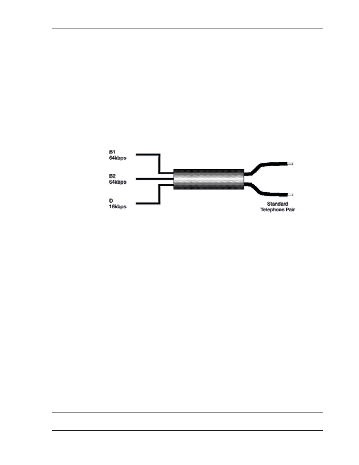
ISDN BRI Multiplexes three bi-directional channels on a single pair of copper
wires
Alphabet Soup: U , S , and N T 1
An ISDN line from the central office is a single copper pair identical to a normal
(unloaded) analog line. When it arrives at the subscriber, it is called the “U” interface. It is
a two-wire connection, usually via a 4-pin RJ-11 style modular jack.
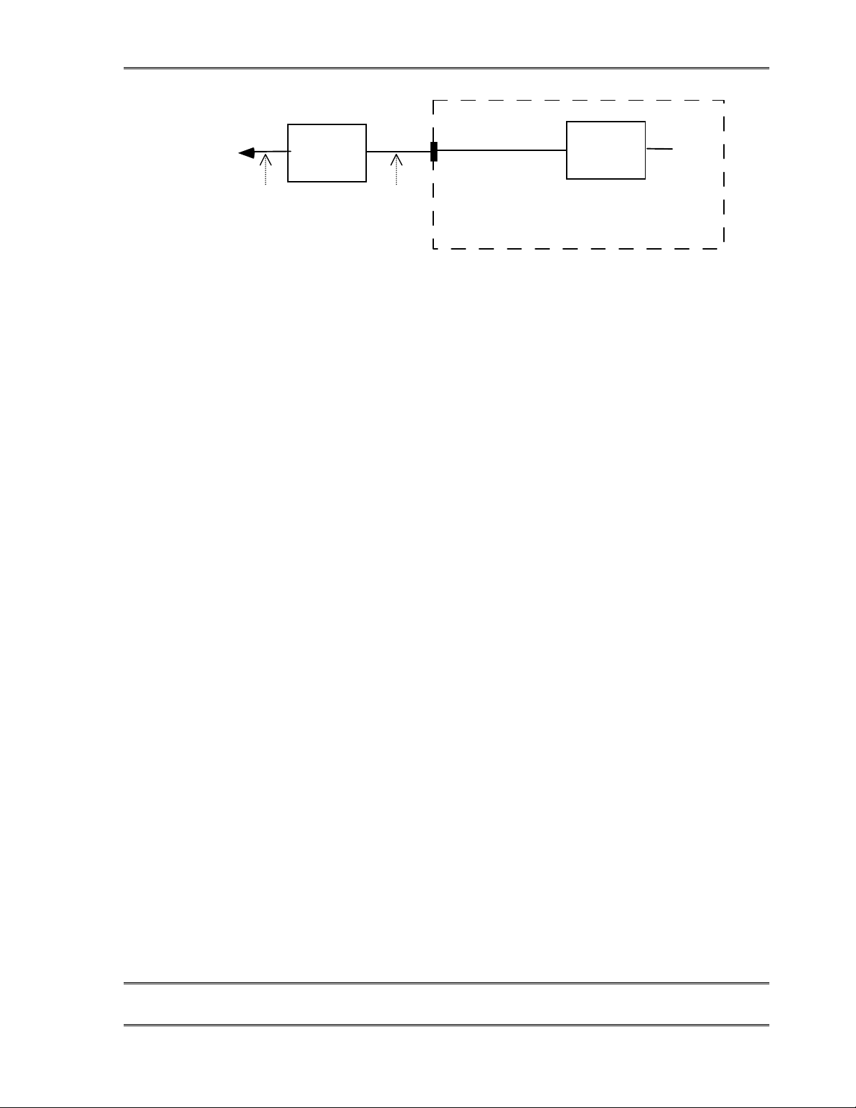
The ‘S’ interface is at the user side of the Network Termination Type 1 (NT1) device. The
NT1 is sometimes generically called a NCTE (Network Channel Terminating Equipment)
or, in some countries an NTBA. It is a four-wire connection, via an 8-pin RJ-45 style
modular jack. (Sometimes the S interface is called S/T. There is a subtle distinction
between the two, but it is not relevant for our purposes here, and the two may be considered
to be the same.)
In the USA & Canada, NT1 functionality is usually included in the terminal equipment. In
other parts of the world, the Telecom Company provides the NT1.
CHAPTER 2 13
INSTALLATIO N
Page 26
TELOS TWOX12 USER’S MANUAL
To
Telco
U
Interface
reference
point
NT1
S/T
Interface
reference
point
In the USA & Canada the NT1 is owned by the end-user whereas in the rest of
the world it belongs to the Telecom Agency.
Only one NT1 may be connected to a U interface. However, as many as eight terminals
may be paralleled onto the S bus.
The North American version of the TWOx12’s ISDN interface has 2 internal NT1s per
interface card with the U interface connectors available at the rear panel.
Section 2.5 has specific information on connecting the unit in various regions of the
world.
2.4 Ordering ISDN – an introduction
This section has a quick overview, for specific information on ordering ISDN see Appendix
6 (Euro ISDN) and Appendix 7 (USA & Canada). The Telos TWOx12 supports the usual
protocol standards:
TA
ISDN EQUIPMENT
ISDN network connection reference points.
For USA & Canada
• National ISDN 1 & 2 (these are the preferred options)
• AT&T “Custom Point-to-Point” (may only allow a single channel)
• Northern Telecom (Nortel) DMS-100 “Custom functional”
For Europe and many other parts of the world
• “Euro ISDN” according to ETS-300 (NET-3, ISDN-2, BRI, S∅)
B and D Channels
The B “Bearer” Channels are the 64 kbps paths that carry the voice audio. The D “Data”
channel is the path between the central office and terminal equipment that is used for call
set-up and status communication. All lines must have a D channel, but there is sometimes a
choice as to the number of enabled B channels.
CHAPTER 2 14
INSTALLATIO N
Page 27
?
t
TELOS TWOX12 USER’S MANUAL
CURIOSITY NOTE!
While the D channel is always present for signaling, it can, in theory, be used for
packet data connections. ISDN lines where the D channel is used for signaling only
are
sometimes
not widely available, and is not used by the TWOx12 or other Telos equipment.
Data and Voice
ISDN lines may be used for voice signals encoded in standard fashion to allow interworking with analog telephones, or may be used to transmit digital data streams. The latter
mode is used for such applications as high-speed Int erne t acce ss. It is als o the mode used
with MPEG codecs, in which case the ISDN line may be carrying voice signals, but is
doing so in a format that is not compatible with the analog part of the telephone network.
The distinction is made in the automatically conveyed “Setup” message that begins each
call.
DEEP TECH NOTE!
The voice mode may well be able to transmit digital data–and some Telephone
Companies charge more money for data capability. That is why some ISDN
“modems” have a special data- over- voice option that fools the central office into
billing as if it were a voice connection.
referred to as 2B+0D rather than 2B+D. D channel packet service is
Normally, the Telos TWOx12 uses only the voice mode, so data capability is not necessary.
Of course, you may use a line with both capabilities with the system at any time. Just be
sure the BRI circuit supports the Circuit Switched Voice (CSV) capability as well as data.
HOT TIP!
If this line may be “borrowed” at times for use with an audio codec, such as the Telos
Zephyr or ZephyrExpress, then you need to be sure that the Circuit Switched Data
(CSD) capability is enabled.
h
Hunt Groups
The most common configuration for on-air phone system is to have the different phone
numbers linked in a “Hunt Group,” also called “Rollover Lines,” or “Incoming Service
Grouping (ISG).” A hunt group allows you to give out a single number to the audience and
CHAPTER 2 15
INSTALLATIO N
Page 28

TELOS TWOX12 USER’S MANUAL
each call will “hunt” to an unused line. Sometimes one or two numbers will be reserved for
a “hot line” or “warm line” in which case those numbers would not be part of the hunt
group.
Special Considerations for Euro-ISDN (ETS 300) users
Some Euro-ISDN implementations deactivate BRI circuits which have been idle for more
than a given length of time. Since this is a normal occurrence, the Desktop Director and
system front panel will not show these lines out of service when this happens. While this
will not interfere with normal operation, it can give a false sense of “security” that
everything is working when, in fact, the circuit could have stopped working. It is
impossible for the Telos TWOx12 to distinguish between a deactivated circuit and a
malfunctioning circuit until you try to use it again. For this reason, if you are using ETS
300 and your phone system is mission critical, you should ask your Telecom Company to
disable this function.
Ordering Help
An appendix to this manual describes the ordering process for ETS 300 (Appendix 6) and
USA/Canada (Appendix 7) ISDN in detail, and include ready-to-go forms that can be used
to order lines from your telephone company. We strongly recommend confirming your
ISDN order in writing using those forms.
CHAPTER 2 16
INSTALLATIO N
Page 29
TELOS TWOX12 USER’S MANUAL
2.5 Connections to the Telco circuits
If you are using analog POTS circuits please read this introductory section and then skip to
section 2.5.3
Introduction – Choices
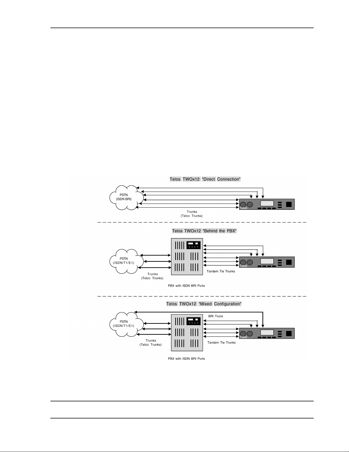
First we must consider if the system will be connected directly to the Telco or will be
“behind” a PBX (private telephone system). The TWOx12 will generally be used
completely independently of any other phone system in your facility. In that case the
system block diagram will look similar to the “Direct Connection” example below.
Another option is to have one or more of the lines come off another phone system as shown
in the “Behind the PBX” and “Mixed Configuration” examples below. If you have a
telephone system capable of generating ISDN BRI on its station side then you may be able
to save money by having it generate some the ISDN BRI lines. See section 2.5.2 for more
on integrating the TWOx12 with a PBX.
The above diagrams illustrate several possible configurations of the TWOx12 and incoming lines.
CHAPTER 2 17
INSTALLATIO N
Page 30
w
TELOS TWOX12 USER’S MANUAL
IMPORTANT!
You will probably receive large number of calls on this system. If your PBX has a PRI
or T- 1 coming from the phone company which will be shared for business
operations, it mayed to be programmed to reserve some capacity for those calls. One
option would be to have the Telco provision (configure) the PRI or T- 1 into separate
trunk groups for the Business and On- air telephone systems.
You should discuss this with both your local telephone service provider and your PBX
provider. It is also important that you inform the Telco that this will be a high
volume application so they can be sure that your contests will not interfere with 911
and other emergency services.
The final option shown offers redundancy. Having at least one line directly from the phone
company keeps your TWOx12 up and running even if one of the two routes is down due to
a bad line.
The next section discusses using the ISDN version of the TWOx12. Skip to section
2.5.3 if you are using analog phone lines.
2.5.1 Connecting the Telos TWOx12 to ISDN
The TWOx12 uses internal plug-in modules to attach to ISDN. These ISDN modules have
two modular jacks accessible through each rear slot, in slots A, B, & C. The type of jack
will be either a 6 position “RJ-11” style or an 8 position “RJ-45” style depending upon
whether it is the version for USA & Canada or the rest of the world.
IMPORTANT TIP!
All ISDN BRI Circuits must use the same protocol (Telco setting). If you are using the
“Mixed Configuration” option, be sure to check what protocols your Telco offers and check
to see that your PBX supports one of the same protocols. Note that National ISDN- 1 is the
most common protocol In the USA & Canada and is available on most ISDN capable
switches in those countries, while ETS 300 is the most popular protocol worldwide.
w
(If you ordered an analog TWOx12 see section 2.5.3)
CHAPTER 2 18
INSTALLATIO N
Page 31
TELOS TWOX12 USER’S MANUAL
ISDN TWOx12 Version
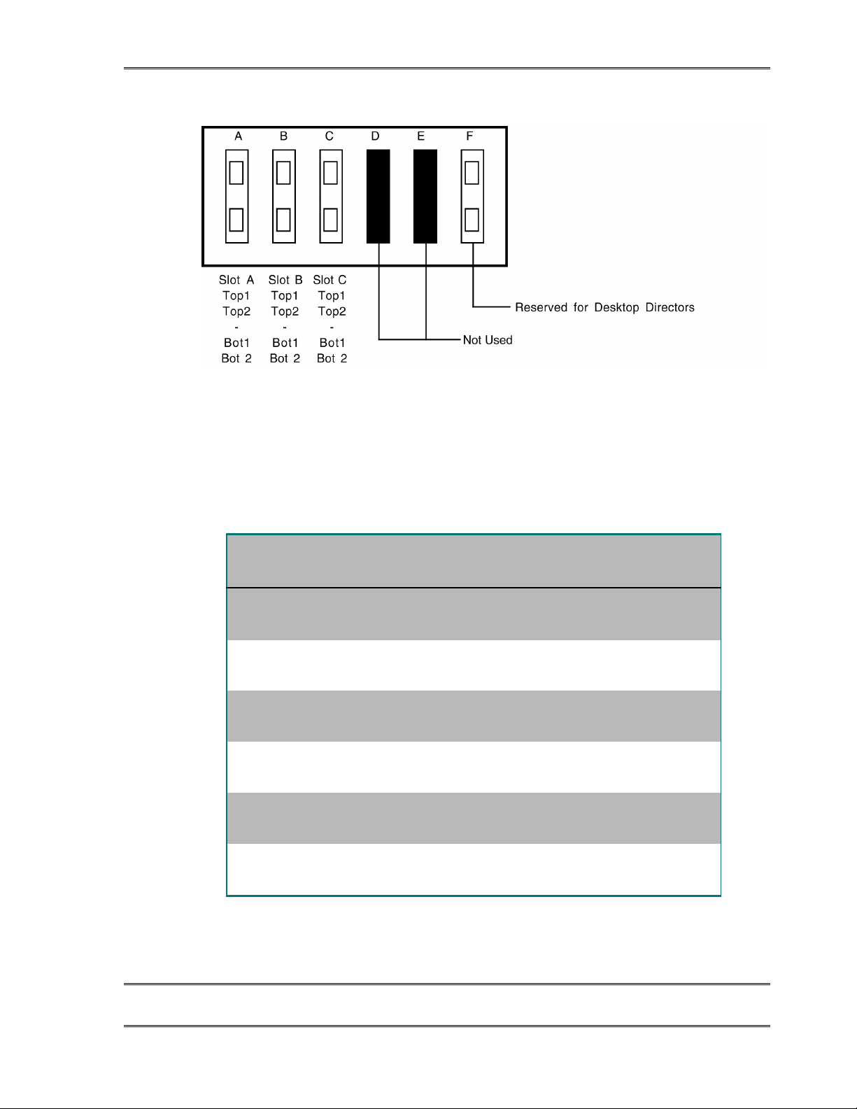
The ISDN version of the TWOx12 has Telco interface cards in slots A, B, & C. Each interface
supports two ISDN BRI circuits. Since each BRI circuit has two Telco channels (or “Lines”) there
are 4 channels per BRI interface card. The ISDN jacks on the rear panel may be either RJ-45 or
RJ-11 style depending on the country.
The correspondence between the interface slot to the system “Line” number for an ISDN
TWOx12 is illustrated in the following table:
Slot Designation Circuit # Channel ID #
System “Line” #
(Telephone #)
A Top1
A Top2
A Bot1
A Bot2
B Top1
B Top2
B Bot1
B Bot2
C Top1
C Top2
C Bot1
C Bot2
This table shows the relationship between the TWOx12’s connectors, the Telco circuits
and the system “line” number for the ISDN TWOx12. See section 3 for a form to organize
1
1
2
2
3
3
4
4
5
5
6
6
this information prior to programming your system.
DN/MSN 1
DN/MSN 2
DN/MSN 1
DN/MSN 2
DN/MSN 1
DN/MSN 2
DN/MSN 1
DN/MSN 2
DN/MSN 1
DN/MSN 2
DN/MSN 1
DN/MSN 2
1
2
3
4
5
6
7
8
9
10
11
12
CHAPTER 2 19
INSTALLATIO N
Page 32

TELOS TWOX12 USER’S MANUAL
In the USA & Canada, a direct connection to the "bare copper" 2-wire U interface is
required. Therefore, the USA & Canada interface module includes an integral NT1 and the
RJ-11 style jack is provided. Users in USA & Canada should follow the hookup
information that follows.
In the rest of the world, the Telephone Company provides the NT1 and the 4-wire ISDN ‘S’
interface will be used via the 8 pin RJ-45 style jack. The ISDN interface in Telos TWOs
shipped to these locations is provided only with this connection. Users outside the USA &
Canada should skip ahead to “ISDN Worldwide (outside the USA & Canada): The
S/T Interface” for hookup information.
ISDN in USA & Canada: Using the U Interface
Connect the ISDN line from the telephone central office directly to the RJ-11 style “U
interface" modular jack on the rear panel ISDN interface using the standard modular phone
cable provided.
U Top (1/2)
To Telco - ISDN
RJ-11 (Standard Modular)
U Bottom (1/2)
To Telco - ISDN
RJ-11 (Standard Modular)
Normal set-up in the USA & Canada. The U jack connects directly to the Telco line and
IMPORTANT!
Your ISDN connections are in the first 3 Interface slots from the left side of the unit as
viewed from the rear of the unit (slots A, B, & C). The RJ- 45 style connectors to the right side
(slot F) are for the Desktop Directors.
w
TWOx12 USA ISDN Interface
NT1 TA
NT1
the S/T jack is unused.
TA
CHAPTER 2 20
INSTALLATIO N
Page 33
w
TELOS TWOX12 USER’S MANUAL
ISDN U interface connector (USA & Canada only)
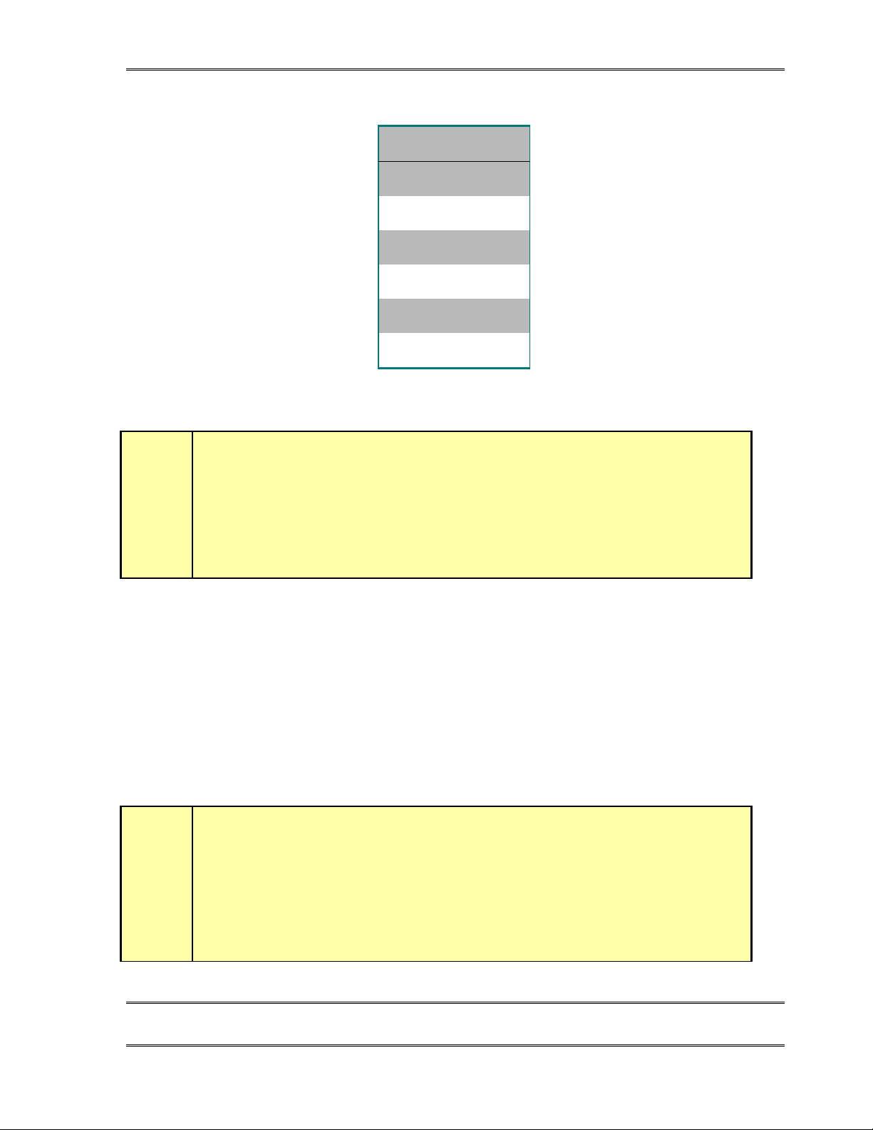
PIN FUNCTION
1 N/C
2N/C
3 Line (R)
4Line (T)
5 N/C
6N/C
ISDN U interface connector as provided on units shipped to the USA & Canada. Note,
the polarity of the line connections should not matter.
IMPORTANT!
As with any piece of modern electronic gear, it is advisable that precautions be taken
to prevent damage caused by power surges. Standard telephone line surge protectors
can be used to offer some degree of protection at the U interface jack. It is the user’s
responsibility to ensure that adequate protection is provided
.
U Interface Status LEDs
The small green LEDs, on the ISDN interface card, near each U jack, indicate the status of
the corresponding ISDN circuit. Normal status is indicated by the LED being lit. Rapid
flashing (about five times per second) indicates a loss of the ISDN at the lowest (physical)
level. If the NT1 can contact the central office (or an active U repeater), the LED will blink
slowly (about once per second). The LED will come on solid when all handshaking is
completed and the basic line connection is good. If each of these LEDs do not light
continuously once you have connected your ISDN circuits, you may wish to skip ahead to
Section 8 for information on troubleshooting the problem.
HOT TIP!
Normally, the Telephone Company should supply an RJ- 11 style jack for the U
interface. This is the same 4 or 6- pin plug used for analog lines. However, sometimes
you may find an 8- pin RJ- 45 style jack–and sometimes you may even be charged
extra for it! If you have this situation, an RJ- 11 plug can be inserted into the center of
an RJ- 45 jack to make things work. If you discover that the Telco charged you extra, be
sure to request a refund!
h
CHAPTER 2 21
INSTALLATIO N
Page 34
TELOS TWOX12 USER’S MANUAL
T
T
ISDN Worldwide (outside the USA & Canada ): The S/T Interface
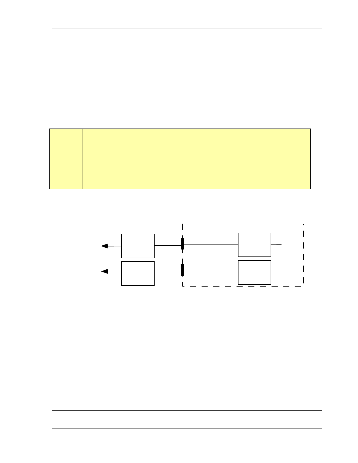
The Telos TWOx12 connects to the NT1 at one of its terminal jacks. The NT1 is sometimes
generically called a NCTE (Network Channel Terminating Equipment) or, in some
countries an NTBA. Use only an 8-conductor RJ-45 style cable. Unshielded twisted pair
category 3 (or higher) cable should be used. The cable details are shown below:
IMPORTANT!
Your ISDN connections are in the first 3 Interface slots from the left as viewed from
the rear of the unit (slots A, B, & C). The 8 pin RJ- 45 style connectors to the right side
(slot F) are for the Desktop Directors.
w
o Telco
o Telco
TWO S/T ISDN Interface
NT1
(NTBA)
NT1
(NTBA)
The usual set-up outside the USA & Canada. The S/T jack is connected to the
S Top (1/2)
RJ-45
S Bot (1/2)
RJ-45
NT1 (or NTBA) provided by the telephone authority.
TA
TA
CHAPTER 2 22
INSTALLATIO N
Page 35
TELOS TWOX12 USER’S MANUAL
ISDN S interface connector
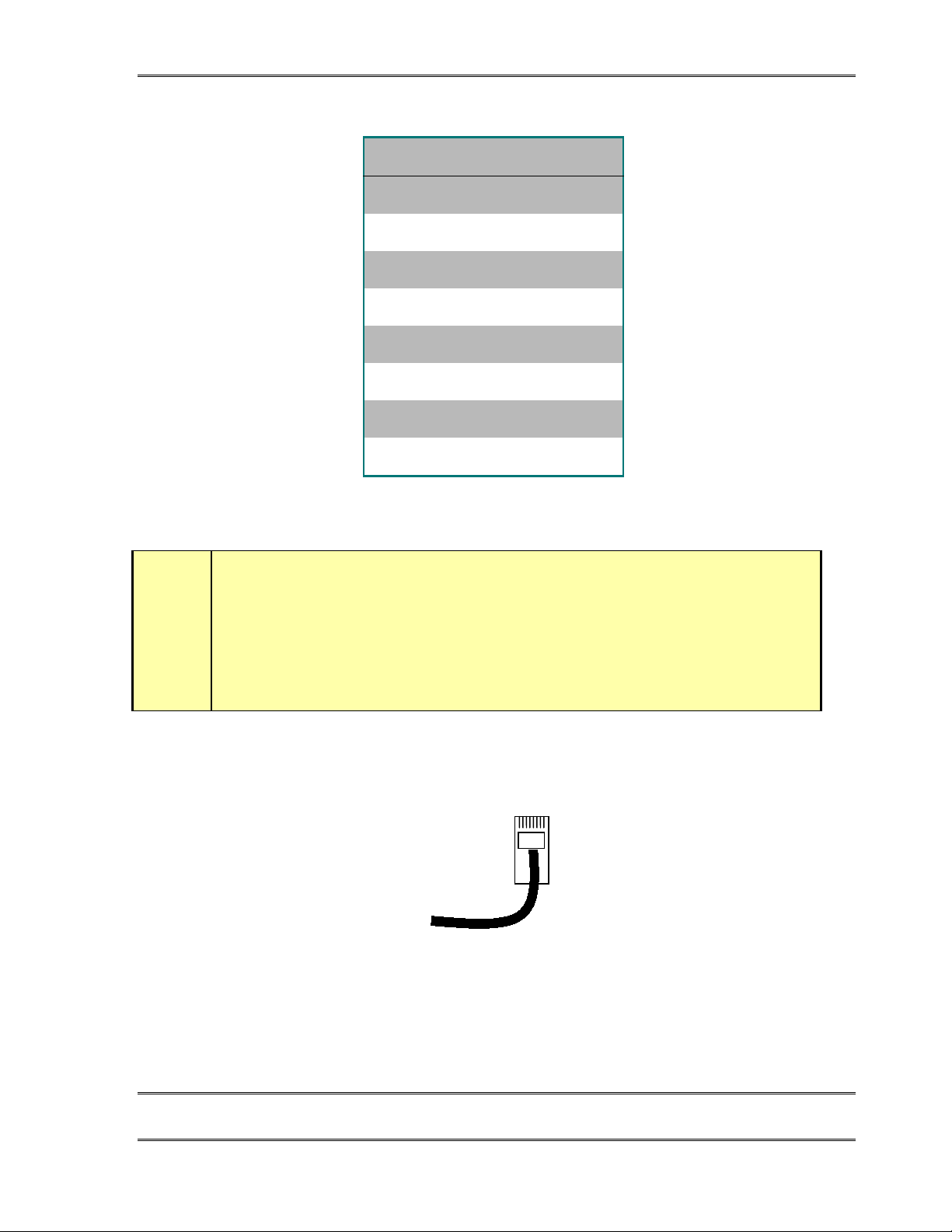
PIN FUNCTION
1 N/C
2N/C
3 S Transmit to network +
4 S Receive from network +
5 S Receive from network -
6 S Transmit to network -
7 N/C
8N/C
The S interface is a standard modular RJ-45 style jack with the pin-out shown above.
w
IMPORTANT!
As with any piece of modern electronic gear, it is advisable that precautions be taken
to prevent damage caused by power surges. Special ISDN S interface surge protectors
can be used to offer some degree of protection at the S interface jack. It is the user’s
responsibility to ensure that adequate protection is provided
ISDN S interface cable
BRI S Interface cable.
Note: Pin 1 is to the left when viewed as above (with pins facing you and at the top).
.
CHAPTER 2 23
INSTALLATIO N
Page 36
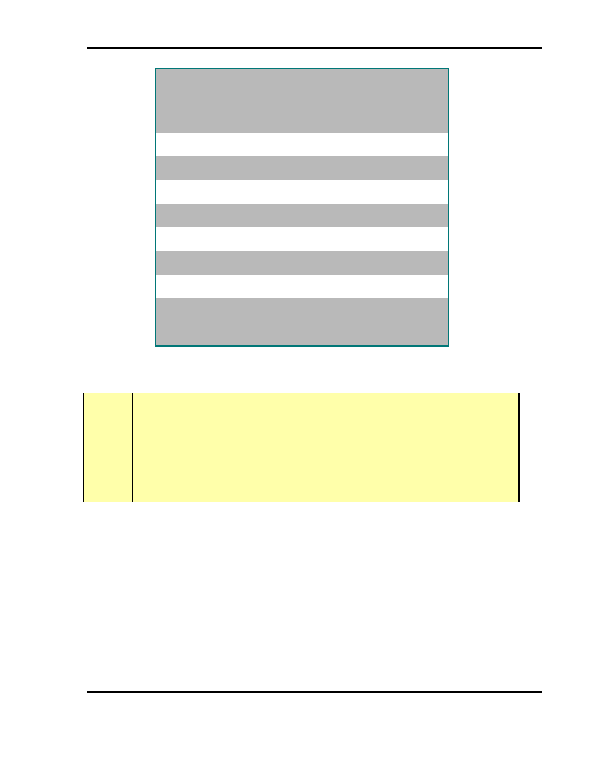
TELOS TWOX12 USER’S MANUAL
PIN TIA 568A
COLOR
1* White/Green PS 3 Power +/ground (Optional)
2* Green PS 3 Power – (Optional)
3 White/Orange Xmt (TE to NT1) to Network +
4 Blue Rcv (NT1 to TE) from Network +
5 White/Blue Rcv (NT1 to TE) from Network -
6 Orange Xmt (TE to NT1) to Network -
7@ White/Brown PS 2 Power 48 VDC – (Optional)
8@ Brown PS 2 Power +/ground (Optional)
*
@
TIA 568ACategory 5 cable wiring diagram. Both ends are wired identically. Note that the S interface
Not used in Telos Products
Not used on the TWOx12
does not require all 8 conductors.
DESCRIPTION
HOT TIP
When fully wired, this cable has 4 twisted pairs wired “straight through” just like the
•
cables often used for Ethernet 10Base- T. The wiring configuration is the same as
TIA 568A (TIA- 568B is electrically equivalent, and can also be used).
Both ends are wired identically.
•
h
The outside pairs are generally not required and may be omitted.
•
The ISDN S interface on the Telos TWO does not provide power. Usually the Telecom
company will arrange for power to the NT1 (NTBA).
2.5.2 Integration with a PBX using ISDN
The TWOx12 has been used satisfactorily using BRI off the following PBX Switches used
in USA and Canada:
Nortel Meridian 2 wire (U interface) [User report]
Please contact Technical Support for the latest information or report you experiences with
other switches.
CHAPTER 2 24
INSTALLATIO N
Page 37
w
i
TELOS TWOX12 USER’S MANUAL
IMPORTANT!
ETS 300 Euro- ISDN is available from many PBX systems outside the USA and
compatibility is generally good. If you are in USA or Canada, however, be sure to read the
next
ISDN TIP
ISDN TIP!
While BRI support is available on a number of PBXs, you should not plan to use ISDN
ports on your PBX for the TWOx12 unless the configuration is on the above list. If not, you
should arrange to test compatibility before purchasing the expansion module for your PBX.
Just because the sales person says it supports National ISDN-1 is not enough!
Compatibility varies widely. Let us know what you discover.
.
2.5.3 Connecting the TWOx12 to POTS (Plain Old Telephone Service) (If you ordered an
ISDN TWOx12 see section 2.5.1)
The TWOx12 uses internal plug-in interface modules to attach to POTS (regular, analog
loop start, telephone lines). These modules have three modular jacks accessible through
each rear slot, in slots A, B, C & D. The type of jack will be a 6 position 4 pin “RJ-11”
style. You will connect the lines to the TWOx12 using the standard modular telephone
cables provided.
The Analog version of the TWOx12 has Telco interface cards in slots A, B, C, & D.
CHAPTER 2 25
INSTALLATIO N
Page 38
TELOS TWOX12 USER’S MANUAL
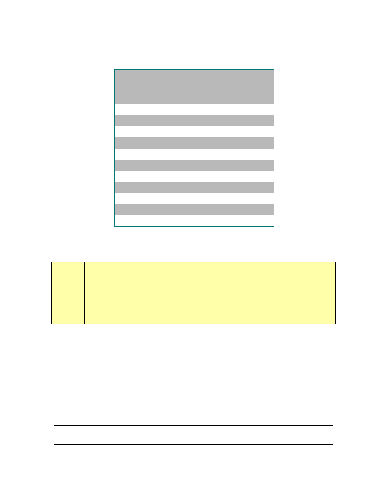
The correspondence between the interface slot to the system “Line” number for an analog
TWOx12 is illustrated in the following table:
Slot Designation Channel ID #
(Telephone #)
A1 1 1
A2 2 2
A3 3 3
B1 4 4
B2 5 5
B3 6 6
C1 7 7
C2 8 8
C3 9 9
D1 10 10
D2 11 11
D3 12 12
The correspondence between slot designation, channel ID (phone number) and system “line”
number is shown above. See section 3 for a form you can fill out to organize this information prior
to programming the system.
System “Line” #
IMPORTANT!
When we say POTS lines we mean just that – Plain Old (analog loop start) Telephone
Service lines. These ports
are uncertain if it is a POTS line
work, and it could cause damage to your system. You can easily check the type of line by
connecting a standard analog telephone to it and check to see if it works.
w
CHAPTER 2 26
A rule of thumb – if it works with an analog modem or fax machine it's safe to connect it!
Most private PBX telephone systems can accommodate “analog ports” for analog “legacy”
equipment such as modems and fax machines. You will need such ports to connect a POTS
TWOx12 to most PBX’s.
must not
be connected to proprietary phone ports off a PBX. If you
connect it to the TWOx12! If it is not POTS it won’t
don’t
INSTALLATIO N
Page 39
TELOS TWOX12 USER’S MANUAL
HOT TIP!
A few years back we always advised that hybrid performance was best when equipment
was connected directly to the lines from the Telco. Today, this is not always true. If the PBX
is connected to the Telco using digital lines (such as T1, E1, PRI, S2, etc), performance
through a digital PBX will generally be better than direct connections to copper analog
circuits. This is particularly if you are located a significant distance from the Telco central
h
office.
The biggest variable when connecting to a PBX analog port is the quality of the analog port.
We have found that many PBX manufacturers offer more than one analog port option. The
better port can usually be distinguished by its higher cost, and the fact that it may offer 48
volts rather than 24 volts. The Telos TWOx12 will work with either voltage, however
experience has shown that the 48 volt version usually has better quality transformers and
other components resulting in better hybrid performance.
The other thing to investigate is whether the PBX offers "Loop Current Drop" or "CPC"
(Calling Party Control) on its analog ports. Without this supervision the TWOx12 will not
be able to determine If a party on hold has hung up, and your talent will get a recording
"please hand up and dial again…" or dial tone when attempting to air the call.
2.5.4 Mixed ISDN/Analog Configurations
Those who desire a system with mixed analog and ISDN connections may replace one of
the interface cards with one of the other type. Section 8.6 lists the part numbers for the
interface cards.
The TWO x12 has been designed to work in the following mixed configurations:
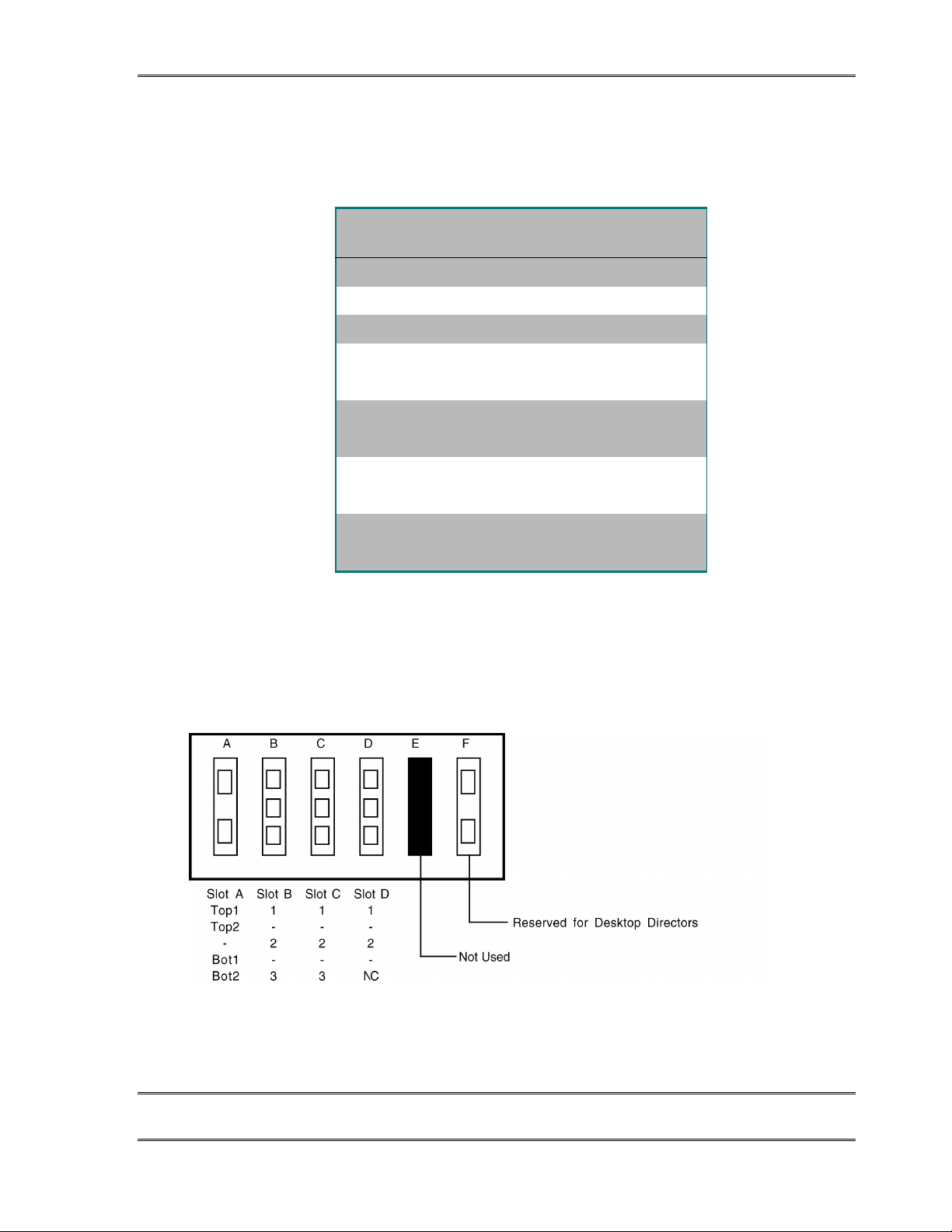
A) 1 Analog interface (slot A) and 2 ISDN interfaces (slots B & C) for a total of 11 lines:
A mixed interface TWOx12 with a POTS interface card in slot A and ISDN interface cards in slots
B, & C. The POTS interface supports 3 circuits while the ISDN interface supports two ISDN BRI
circuits. Since each BRI has two Telco channels (or “Lines”) there are 4 channels per BRI
interface card. This configuration has a total of 11 channels.
CHAPTER 2 27
INSTALLATIO N
Page 40
TELOS TWOX12 USER’S MANUAL
The correspondence between the interface slot to the syst em “Lin e” numbe r for the above
mixed TWOx12 configuration is illustrated in the following table:
Slot
Designation
Channel ID #
(Telephone #)
System
“Line” #
A1 1 1
A2 2 2
A3 3 3
B Top1
B Top2
B Bot1
B Bot2
C Top1
C Top2
C Bot1
C Bot2
This table shows the relationship between the TWOx12's connectors, the Telco circuits, and the
system "line" numbers for the mixed ISDN/POTS TWOx12 described above. See section 3 for a
form you can use to organize this Information prior to programming your system.
4 (DN/MSN 1)
4 (DN/MSN 2)
5 (DN/MSN 1)
5 (DN/MSN 2)
6 (DN/MSN 1)
6 (DN/MSN 2)
7 (DN/MSN 1)
7 (DN/MSN 2)
4
5
6
7
8
9
10
11
B) 1 ISDN interface (slot A) and 3 Analog interfaces (slots B, C, & D) for a total of 12
lines (note that the bottom jack of the analog card in slot D will be inactive in this
configuration)
A mixed interface TWOx12 with an ISDN interface card in slot A and POTS interface cards in slots
B, C, & D. The ISDN interface supports two ISDN BRI circuits while POTS interface supports 3
circuits. Since each BRI has two telco channels (or “Lines”) there are 4 channels per BRI interface
card. Since the TWOx12 is a 12 line system, the last POTS port (D3) is not used in this
configuration.
CHAPTER 2 28
INSTALLATIO N
Page 41

TELOS TWOX12 USER’S MANUAL
The correspondence between the interface slot to the syst em “Lin e” numbe r for the above
mixed TWOx12 is illustrated in the following table:
Slot
Designation
A Top1
A Top2
A Bot1
A Bot2
Channel ID #
(Telephone #)
1 (DN/MSN 1)
1 (DN/MSN 2)12
2 (DN/MSN 1)
2 (DN/MSN 2)34
System “Line” #
B1 3 5
B2 4 6
B3 5 7
C1 6 8
C2 7 9
C3 8 10
D1 9 11
D2 10 12
D3 Not Used Not Used
This table shows the relationship between the TWOx12's connectors, the Telco circuits, and the
system "line" numbers for the mixed POTS/ISDN TWOx12 described above. See section 3 for a
form you can use to organize this Information prior to programming your system.
Other than the physical interface, your system will work as usual in the above mixed
configurations. You will need to follow the information in section 2.5.1 for information
about connecting ISDN and the information in section 2.5.4 for informa tio n about
connecting analog lines.
CHAPTER 2 29
INSTALLATIO N
Page 42
TELOS TWOX12 USER’S MANUAL
2.6 Studio Audio Connections
2.6.1 Mix-Minus
What is a mix-minus?
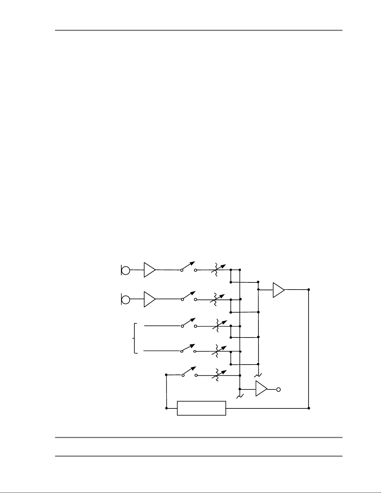
The Telos TWOx12 must be fed send-to-caller audio which is free of the caller audio, a
“mix-minus”. A mix-minus is a mix of all of your audio sources which will be placed onair (or recorded) except the incoming caller audio–thus the “mix-minus” designation. The
European term “mix minus one” is a clearer term for the typical situation. A mix-minus is
also sometimes referred to as a “clean feed”. Most mode rn cons ole s (m ixin g desks) ar e able
to handle one or two of these, but more may be difficult. In that case it may be necessary to
get creative. The important thing to remember is that the hybrid must not “chase its tail,”
where its output makes its way somehow back to the input.
Some exa mpl es:
Example 1: Using a broadcast console (mixing desk)
A multibuss stereo broadcast conso le is in use. Progr am is used to feed the transmi tter and
Audition is used for some other application. A third buss, “Utility,” is not in use, so we will
use this to create a mix-minus for a single hybrid.
All sources, including the hybrid, will be assigned to Program, so the audience can hear
them, as usual. We will also assign most of these sources to Utility as well, just never the
fader representing the hybrid’s own audio.
"
MICRO-
PHONES
UTILITY
BUS
LINE
CHANNELS
PHONE
CHANN EL
PROGRAM
OUT
PROGRAM
Hybrid
SendRcv
BUS
CHAPTER 2 30
INSTALLATIO N
Page 43
c
TELOS TWOX12 USER’S MANUAL
MIX- MINUS TIP!
This arrangement is very flexible as it allows the operator to place any or all sources
in Utility for the caller to hear. Also, if the talent wishes to talk about the caller
without him/her hearing, the talent’s microphone need only be taken out of Utility to
do so.
The only drawback to this approach is the potential for the operator to accidentally
put the hybrid in Utility, in which case it is no longer a mix- minus.
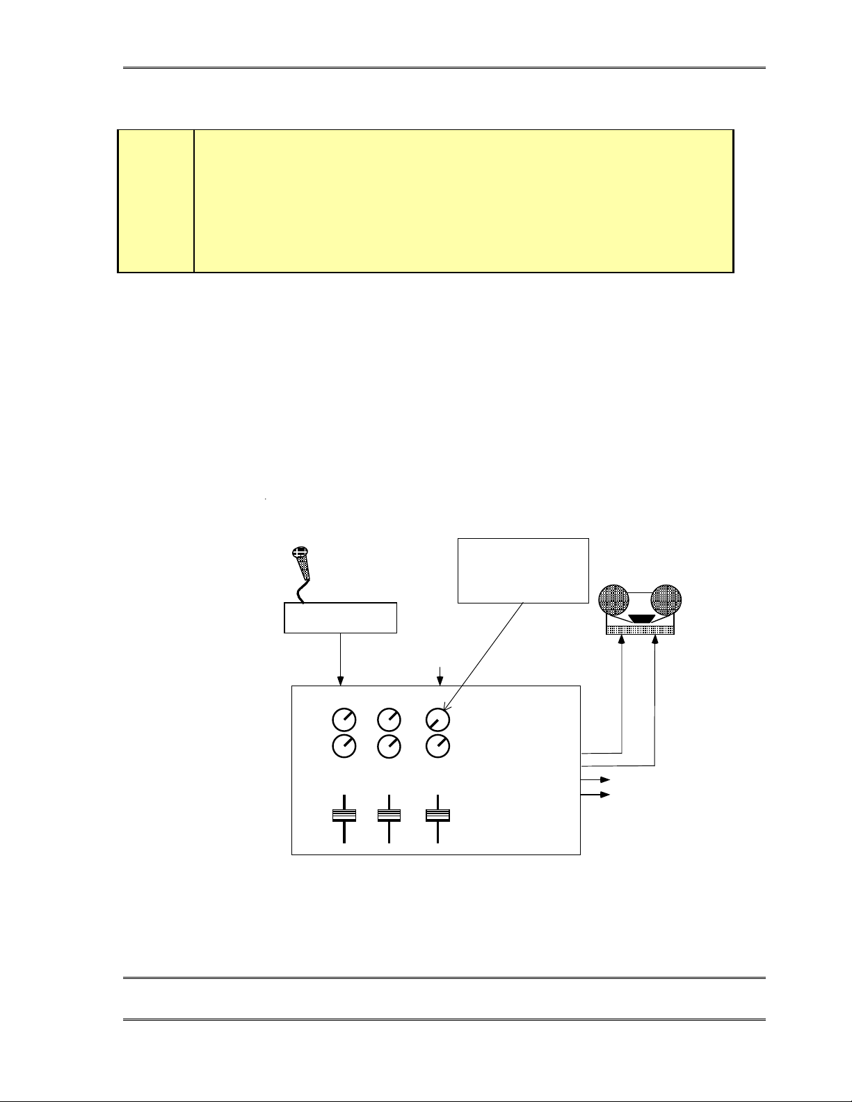
Example 2: Using a utility mixer
A general purpose utility mixer is used to record interviews off the telephone line using a
single hybrid. The mixer’s main bus is fed to the recording device. Both the microphone
and the hybrid will be brought up on the faders so the interview can be recorded.
Again, we will use a second buss to feed the hybrid. In this case, we will take the Aux 1
output to feed the hybrid. We will turn up Aux 1 for the microphone but we will make sure
it is turned fully off for the input channel with the caller audio.
Mic Preamp
AUX 1
AUX 2
Mic1
OUTPUT
FROM
HYB #1
Caller
:
NOTE
This must be turned
down or AUX 1 will no
longer be a mix-minus!
UTILITY
MIXER
LEFT OUTPUT
RI GHT OUTPUT
AUX 1 O UT
AUX 2 O UT
TO HYB #1 "IN"
CHAPTER 2 31
INSTALLATIO N
Page 44
Why do I need a mix-minus?
Adaptive hybrids, commonly used in broadcast applications since Telos pioneered the
technology, work by comparing the audio sent to the audio received. The system then
adjusts itself to minimiz e send audio in the audio com ing back (i. e. min im iz es leaka ge).
Thus the audio fed to the hybrid is, in effect, a reference signal. If the audio sent into the
hybrid contains the caller audio (the audio we want) then there is no reference signal and
the system cannot do its job.
CURIOSITY NOTE!
This is why we at Telos do not claim our hybrids will work without a mix minus.
Sure, they might work without a mix- minus (it has been done), giving borderline
performance, but that’s not good enough. Do the job right and use a mix- minus!
?
An additional problem is the potential for feedback through the hybrid. In any real world
situation there will be some leakage of the send audio into the received audio. With gain
through the AGC and console, this path creates a loop and feedback can occur. The Telos
TWOx12’s extremely low leakage makes this scenario unlikely, however a clean mixminus is still essential for optimal performance.
TELOS TWOX12 USER’S MANUAL
More on Mix-Minus
Simple Mix-Minus
The simplest way to create a mix-minus is to use a distribution amp to feed the mic preamp
output directly to the hybrid, as well to the board (mixer, console, mixing desk). This
approach lacks flexibility, and require s addit ion al equipm ent if mo re than on e mic is used
and/or more than one mix-minus is required.
Sophisticated Mix-Minus
Most modern broadcast consoles have some provision for mix-minus. The best allow
selective feeds to the phone system. This is useful since sometimes you want only one mic.
feeding the phone, sometimes you want to three or four mics (during the morning show, for
instance), and sometimes you want to play a cart machine, CD, or other device when callers
need to hear and react to contest sound effects, etc. Some even provide for separate “on
line” and “off line feeds”. And when two hybrids are used, each caller will normally need a
separate mix-minus since each hybrid will need to have the output of the other, if callers are
to hear one another (actually, the TWOx12 allows for a single Mix-Minus, though it is less
flexible, see section 7.3.1 for details). A simplified figure of a two-buss two-hybrid mixminus configuration follows:
CHAPTER 2 32
INSTALLATIO N
Page 45
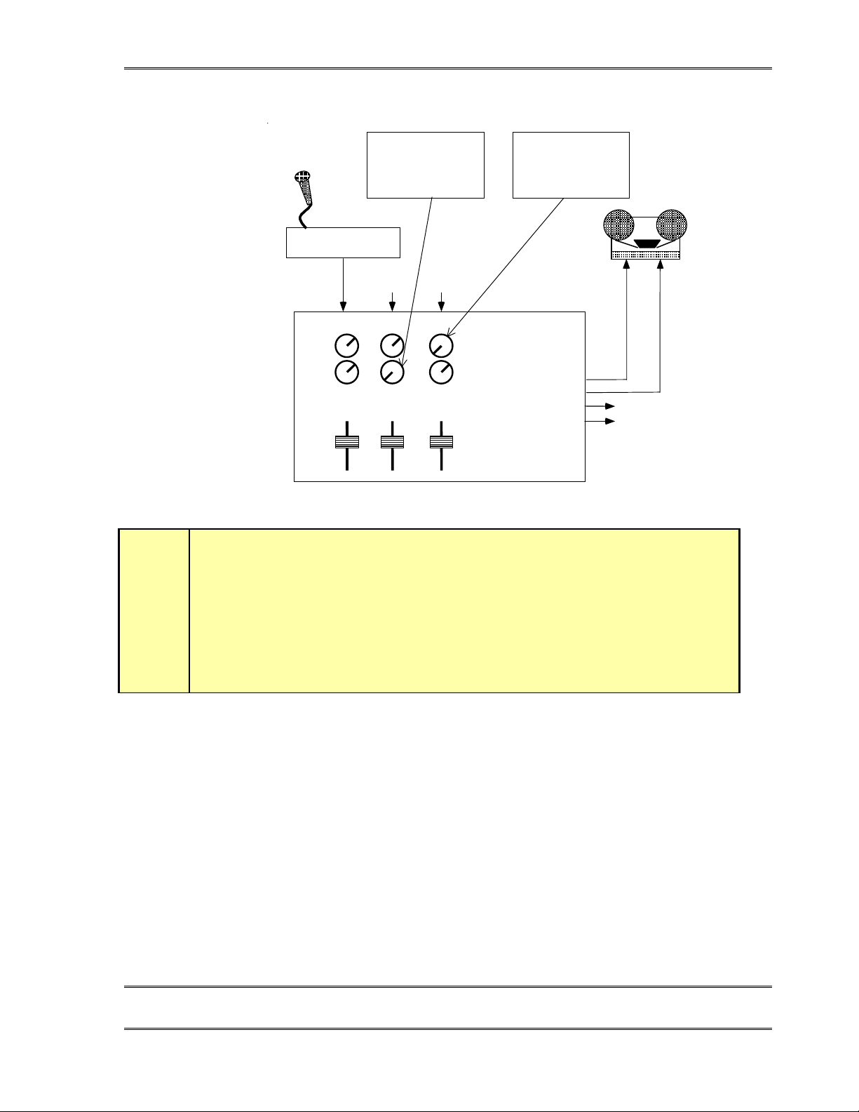
TELOS TWOX12 USER’S MANUAL
h
:
NOTE
This must be turned
down or AUX 1 w ill no
longer be a mix-M inus
Mic Preamp
:
NOTE
This must be turned
down or AUX 2 w ill no
longer be a mix-M inus
OUTPUT
FROM
HYB #1
OUTPUT
FROM
HYB #2
UTILITY
AUX 1
AUX 2
Mic1
Caller1 Caller2
HOT TIP!
While we are on the subject, we’ll digress here for a moment. Many hybrid installation
problems are caused by an inadvertent signal path which creates a loop from the
hybrid’s output back to it’s own input. Some consoles allow this when certain control
combinations are selected by the user. In some cases it may be as simple a mistake as
assigning the hybrid to whichever buss is feeding the hybrid. This is the first place to
look when strange or erratic performance is experienced. The quickest test is to bring
up only the hybrid in question on the board and select a line. Dial tone should not
appear on the send meter of the hybrid in question.
MIXER
LEFT OUTPUT
RI GHT OUTPUT
AUX 1 OUT
AUX 2 OUT
TO HYB #2 "IN 2"
TO HYB #1 "IN 2"
No mix-minus at all: Feed Thru - The Special Downstream Mode
The Telos TWOx12 may be used downstream of the studio console. In this case, the hybrid
adds the caller to the input and passes the summed result on to the output. This method
avoids the need for a mix-minus feed. The TWOx12’s Feed Thru option in the Audio menu
(see section 7.3.1) is enabled to create this mode.
All audio is sent into the TWOx12 where the caller audio is mixed in. The resulting mix is
output from the TWOx12’s Output (Caller) outputs.
CHAPTER 2 33
INSTALLATIO N
Page 46
Phones and Remotes
When on remote, to save money and hassle, calls are usually received at the studio, rather
than at the remote site. In this situation, calle r audio mus t be fed to the remote tale nt so th at
they can hear and respond to callers. Moreover, the cal le rs need to hear the ta len t. In many
cases, the remotes are sufficiently distant that talent cannot monitor the station for the caller
feed. Even if they could, the profanity delay would be a problem, since the talent needs to
hear the callers pre-delay.
All perceptual codecs (Such as the Zephyr or ZephyrExpress) have too much delay for
talent at remote locations to hear themselves via a round-trip loop. Therefore, another mixminus is required to feed the codecs.
The talent hears callers via the codec return path. As before, you feed this return with mixminus: a mix of everything on the program bus minus the remote audio.
As for the second half of the equation, the callers hear the talent beca use the re mo te feed is
added to the telephone mix-minus bus. This is no problem if you have a set-up that permits
selective assignment to the hybrid mix-minus.
TELOS TWOX12 USER’S MANUAL
c
MIX- MINUS TIP!
If you cannot create a separate mix- minus for occasional remotes, you may be able
to borrow one of your hybrid mix- minuses and console input for the duration of the
remote. Just make sure that your operators understand that only one of the two
hybrids is active.
A problem with this arrangement is a result of a hybrid with too much leakage combined
with the system delay. If the hybrid isn't doing a good job of preventing the send audio
from leaking to its output, the special remote send mix-minus is corrupted. Remember, if
any of the announcer audio from the remote site is returned via the monitor feed, it will be
delayed by the digital link, causing an echo effect.
The Telos TWOx12 really shows its stuff in this situation. Because it has so much transhybrid loss, the leakage is not at all likely to be a problem. When there is a proble m, you
can solve it by increasing the DuplexLevel (ducking) selection in the Audio menu. See
section 7.3.1 for details.
CHAPTER 2 34
INSTALLATIO N
Page 47
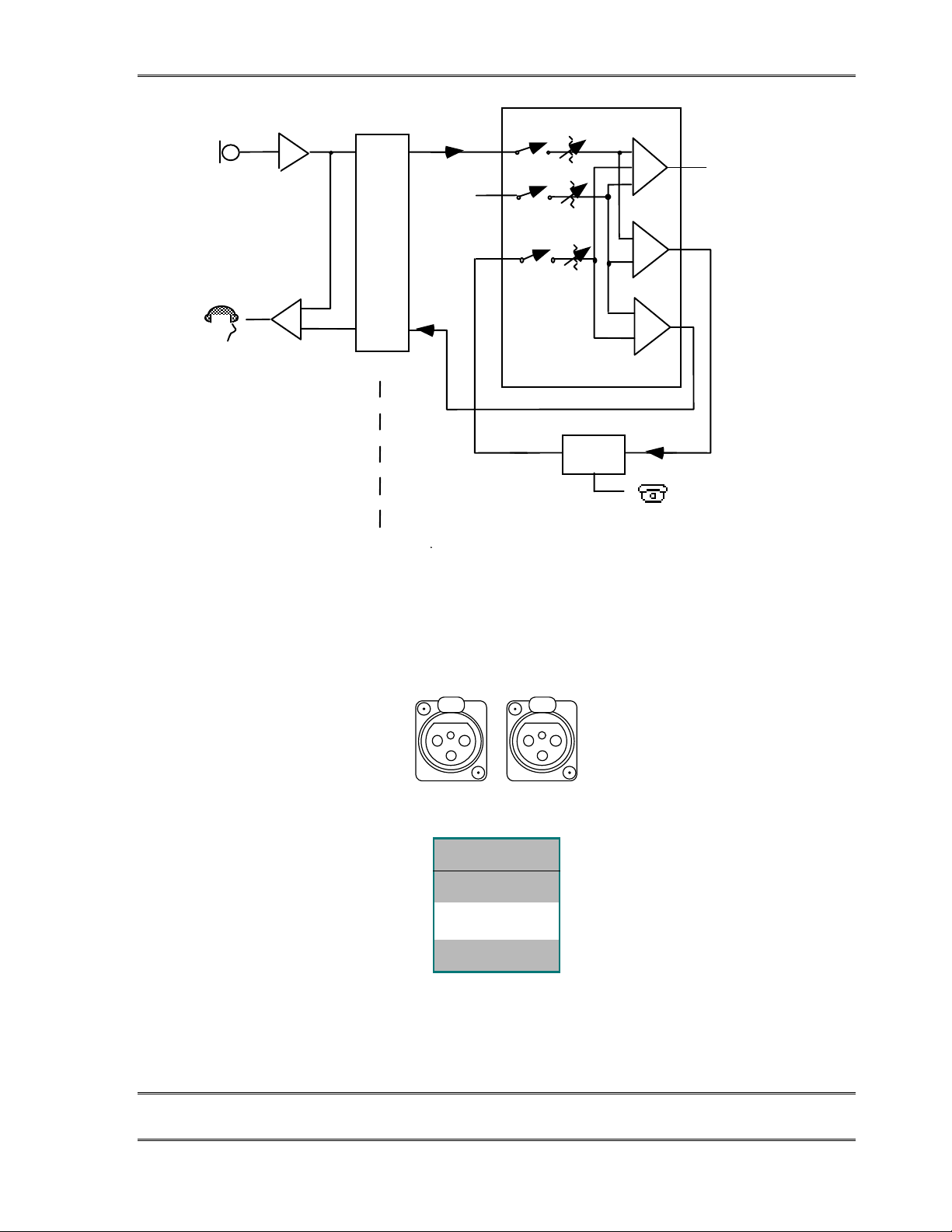
TELOS TWOX12 USER’S MANUAL
m
Microphone
Zephyr
Trans-
mission
Path
Other Sources
for music, etc.
Σ
Talent Headset
REMOTE SITE STUDIO
Studio Console
Phone
Hybrid
Σ
Telephone
Σ
Mix-Minus
Σ
Diagram showing system set-up for remotes with delay in the transmission path and calls taken at
the studio.
Main Progra
Output
Remote
Mix-Minus
2.6.2 Input- (To Caller ) Left & Right Analog Audio
INPUT – (TO CALLER)
1 2
PINFUNCTION
1 Ground
2
Audio +
3 Audio -
The analog audio inputs have the following characteristics:
CHAPTER 2 35
INSTALLATIO N
Page 48
h
TELOS TWOX12 USER’S MANUAL
• Active balanced
• Line level: -7 to +8 dBu nominal level (See section 3.4.1).
• Headroom: 13dB
• Bridging ≥ 100KΩ impedance
The inputs are designed to be sourced from balanced, line level signals. Older equipment
with a transformer output stage may need a terminating resistor across pins 2 and 3, consult
the manual for your equipment for how to use it with high impedance inputs.
Unbalanced sources may be used by connecting pins 1 & 3 to the source ground while the
signal high is connected to pin 2.
HOT TIP!
The signal fed to these inputs should be a mix-minus or system performance will be
severely degraded. The only exception Is when the Feed Through option Is used.
See section 2.6.1 for details on mix- minus and section 7.3.1 for Information on the
Feed Through option.
The sensitivity of the send inputs are adjusted using the Audio menu Input Gain selection.
You will need to set these according to the levels expected at the Hybrid input. When in the
studio in position, the left LED level meter indicates the level after the menu adjustment,
but before any of the Hybrid’s digital level adjustments. See Section 3.6 & Section 7.3.1 for
additional informatio n.
CURIOSITY NOTE!
The Telos TWOx12 has the more common pin- outs used for three pin XLR inputs &
outputs. You can easily remember the correct signals when wiring connectors using
the phrase “George Washington Bridge.” Pin 1 = G = Ground, Pin 2 = W = “+” = White
(typical color in mic cable, if there is no white there will be a red conductor), and Pin 3
= B = “- ” = Black.
?
2.6.3 POH (Program on Hold) Input
This analog input is for whatever audio you want callers to hear when put on hold, usually
your main program feed. This is a three pin XLR female with the same input pins as the
main inputs. Clipping point is +21dBu.
CHAPTER 2 36
INSTALLATIO N
Page 49
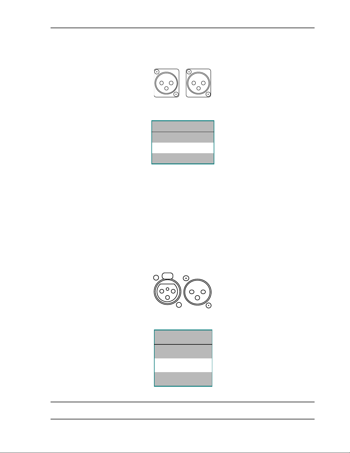
TELOS TWOX12 USER’S MANUAL
2.6.4 Output – (Caller) Left & Right Audio
Output – Caller
12
PIN FUNCTION
1 Ground
2 Audio +
3 Audio -
The analog audio outputs have the following characteristics:
• Active differential
• Output level: -7 to +8 dBu, nominal (See section 3.4.1 for setting this parameter).
• Clip point: +21dBu.
• Impedance: < 60Ω x 2
If a single-ended (unbalanced) output is required, connect between ground and either of the
output pins. Do not ground the unused pin.
2.6.5 AES/EBU Digital Audio In/Out
AES/EBU
OUT IN
PIN FUNCTION
1 Ground
2Output +
3 Output 0
AES/EBU Input & Output Connections
CHAPTER 2 37
INSTALLATIO N
Page 50

TELOS TWOX12 USER’S MANUAL
These are inputs and outputs for AES/EBU format digital audio signals.
Input
110 Ω. This input is internally sample-rate converted, so may accept sources at any of the
common rates, from 32 to 48 kHz. See section 7.3.1 for setting this parameter.
The left input of this AES/EBU stream will be fed to Hybrid 1, while the right input will be
fed to Hybrid 2 (the internal routing of these two signals can be changed using the Routing
option in the Audio menu). Because of this fact you may need an external AES/EBU router
or mixer to provide this stream. An alternative would be to use a routing option requiring
only a single mix-minus (see Routing in section 7.3.1) or the analog inputs.
Such mixers are available from Nvision as well as other suppliers (www.nvision1.com 800-
719-1900 or 530-265-1021, See # NV1055).
HOT TIP!
The signal fed to these inputs should be a mix-minus or system performance will be
severely degraded.
See section 2.5.1 for details on mix- minus
h
Output
110 Ω. The output can be synced and sample-rate converted to either the frequency of the
AES IN signal, or locked to the ISDN network clock/system clock (@ 48kHz), depending
upon a parameter in the Audio menu. Even if you are using the Analog inputs the
AES/EBU input can be fed a reference signal to provide output synchronisation.
Because both the left and right channels are combined on one AES/EBU signal, you may
have to use a routing switcher, distribution amp, or console routing function to direct the
two signals appropriately for your installation. An alternative would be to bridge 2
AES/EBU inputs across this output, which is generally an acceptable practice.
You can find more information about setting the AES Out sync modes in section 7.3.1.
2.7 Desktop Director™ Connections
The TWOx12 has 2 Desktop Director™ ports located in slot F of the system. Each port
supports 1 Desktop Director™ directly. A second Desktop Director can be added to each
port (for a total of 4) using a Desktop Director Expander Kit (part number 0212-1400)
available from your Telos Dealer. Each expander kit allows one additional Desktop
Director. An expander kit is also required for any Desktop Director located more than 250
feet (75 meters) from the TWOx12.
CHAPTER 2 38
INSTALLATIO N
Page 51
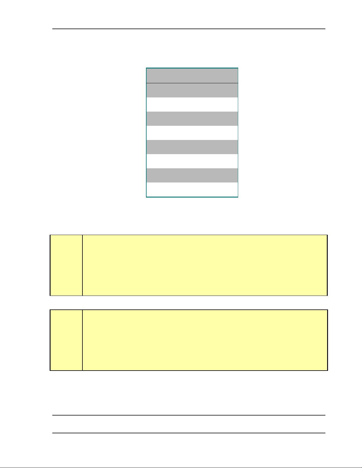
TELOS TWOX12 USER’S MANUAL
Jack on Desktop Dire ctor™
PIN FUNCTION
1 Not used
2Not used
3 S Transmit to 2X12 +
4 S Receive from 2X12 +
5 S Receive from 2X12 -
6 S Transmit to 2X12 -
7* Power Sink –
8* Power Sink + (Top)
e
t
The interface connector on the Desktop Director™ is a standard modular RJ-45 style jack.
IMPORTANT!
Be very careful to label wiring used with RJ-style connectors. In some cases they have power
on them, and there is a risk of applying this power to something which does not expect it.
For this reason we suggest that you use different colored cables (or connector boots) on the
Desktop Director cables versus your Ethernet & ISDN Cables.
DEEP TECH NOTE!
If the above wiring table looks familiar to you, that’s not surprising, this looks just like the
ISDN S interface on any piece of ISDN terminal gear! That’s not a coincidence, our work
with ISDN led to using this robust interface for other purposes as you see here.
CHAPTER 2 39
INSTALLATIO N
Page 52
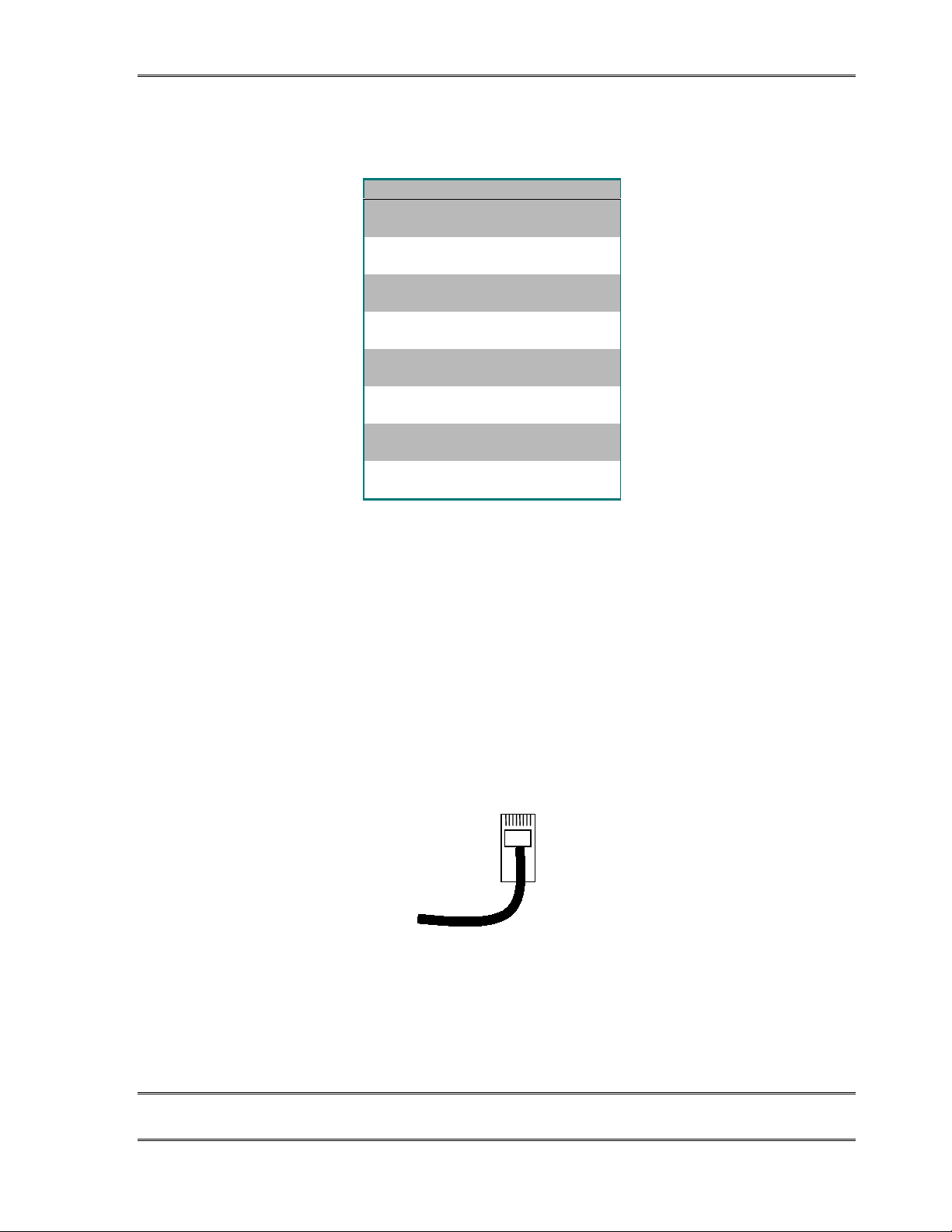
TELOS TWOX12 USER’S MANUAL
TWOX12 Desktop Director™ Ports (interface slot F)
PIN FUNCTION
1 Not used
2Not used
3
S Receive from Director +
4 S Transmit to Director +
5 S Transmit to Director -
6 S Receive from Director -
7* PS2 Power Source -
8* PS2 Power Source +(Top)
The TWOx12 has 2 Desktop Director™ ports in Interface slot F. Power is provided on pins 7 & 8 for
one Director per port. If more than one Desktop Director™ is required on a single port an external
power supply will be required (see below).
This interface is a standard modular RJ-45 style jack and is has the data pairs
exchanged as compared to an ISDN S interface or the Desktop Director. Therefore a
“straight through” (non-crossover) cable is used between the TWOx12 and the Desktop
Director as follows.
Desktop Director™ Cable
Note: Pin 1 is to the left when viewed as above (with pins facing you and at the
top).
CHAPTER 2 40
INSTALLATIO N
Page 53
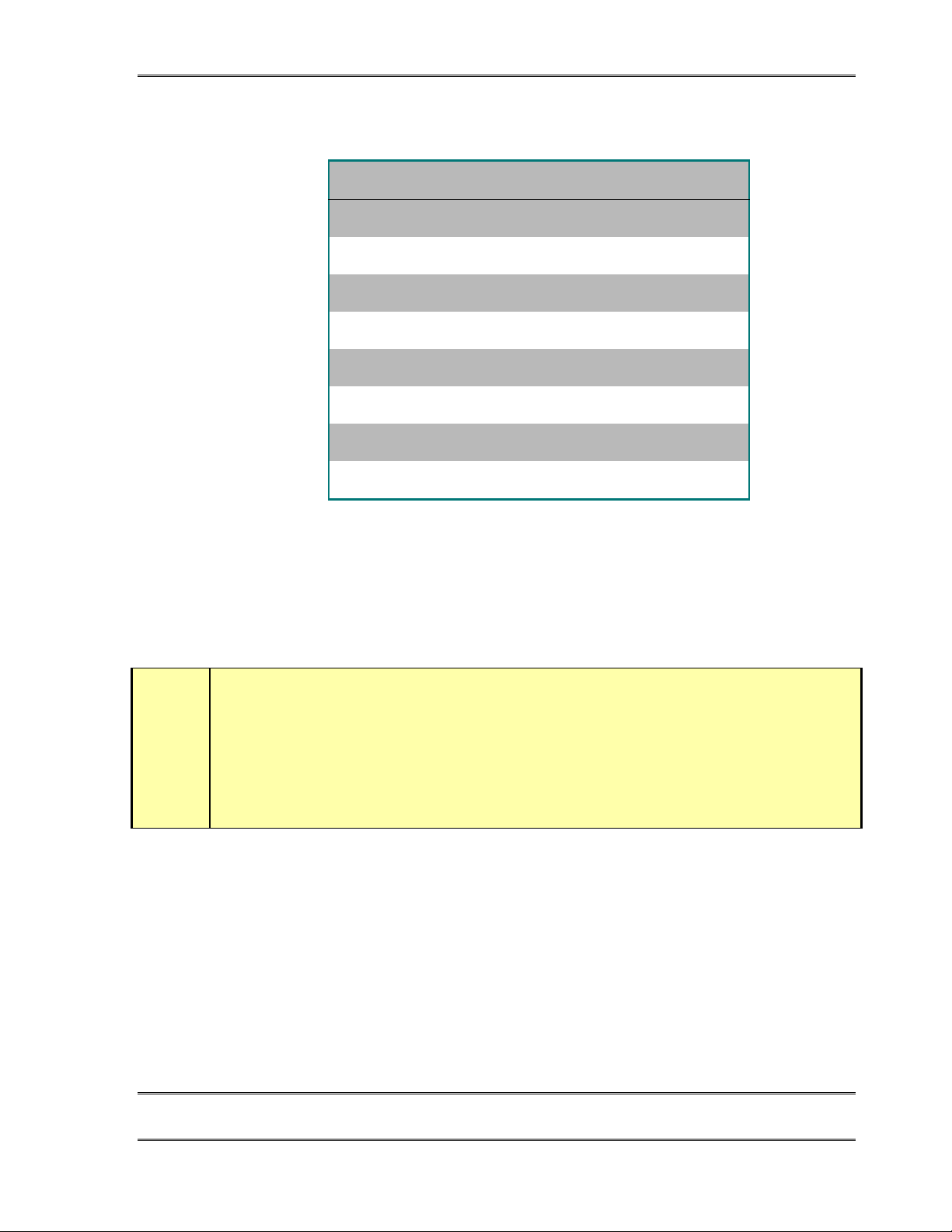
TELOS TWOX12 USER’S MANUAL
PIN COLOUR DESCRIPTION
1 White/Green Not used
2 Green/ Not used
3 White/Orange Xmt (TE to NT1) to Network +
4 Blue Rcv (NT1 to TE) from Network +
5 White/Blue Rcv (NT1 to TE) from Network -
6 Orange Xmt (TE to NT1) to Network -
7 White/Brown PS 2 Power - 48 VDC
8 Brown PS 2 Power ground (+)
Desktop Director™ cable wiring diagram. TIA 568A or 568B standard Category 5
cables may be used. Both ends are wired identically.
The signal to the Desktop Director™ is electrically similar to the ISDN S interface.
This connection is limited to 2300 Feet (700 meters) and wiring should be configured
using the extended passive bus configuration (see below for some examples).
HOT TIP!
Since category 5 wire is so common (and prices have dropped) we recommend that you use it
instead of category 3 wire for the ISDN, Ethernet, and Desktop Director™ wiring.
h
Wiring Configurations for the Desktop Director™
Each Desktop Director™ is supplied with a 25-foot cable which is used to make this
connection. You can make your own cables as long as they follow the wiring shown above.
Category 3 type (Cat 3) or higher cable must be used; we suggest Category 5 type (Cat 5)
wire. The usual configuration of two Desktop Directors involves merely plugging in this
supplied cable to the Director and TWOx12 as illustrated below:
CHAPTER 2 41
INSTALLATIO N
Page 54
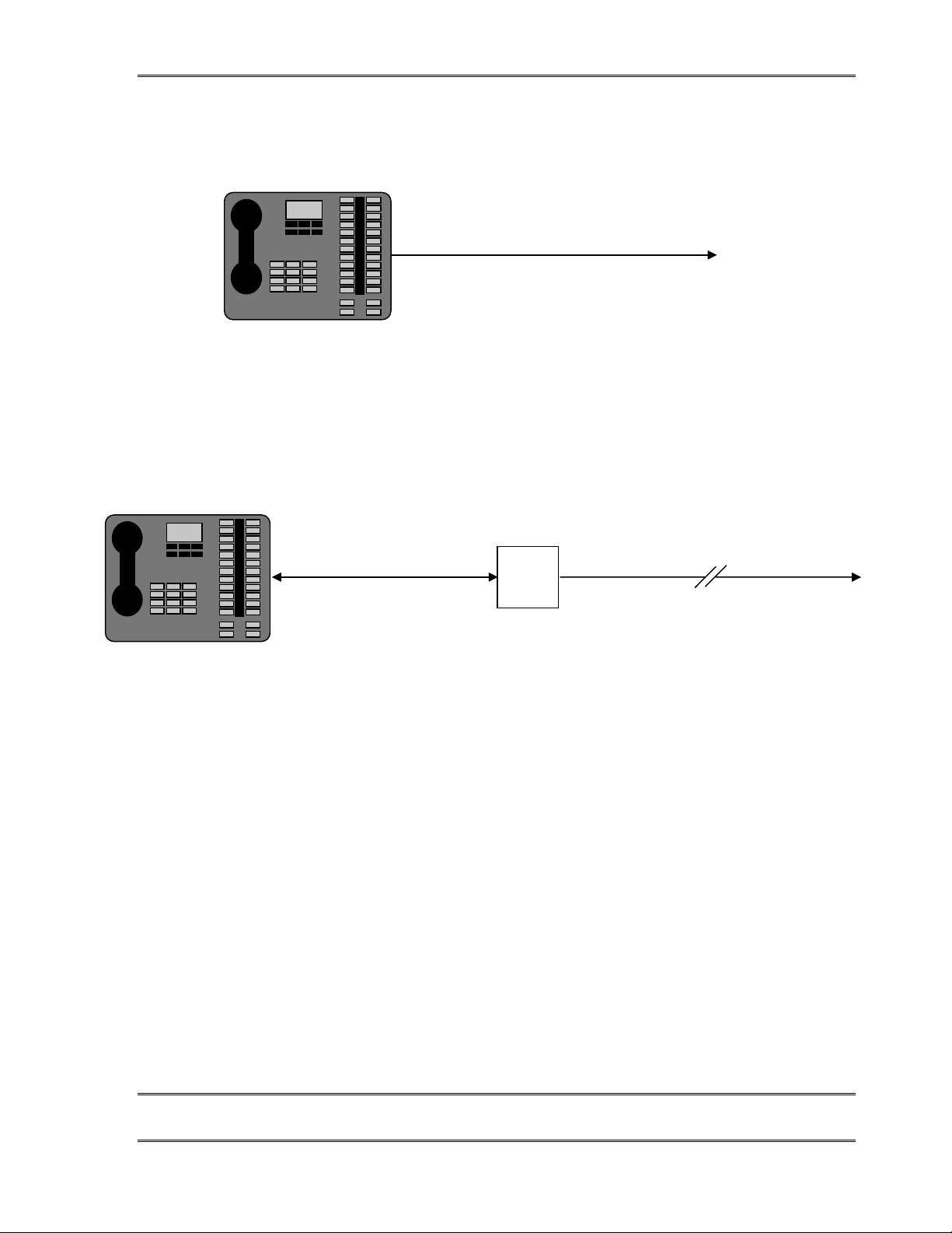
TELOS TWOX12 USER’S MANUAL
p
p
(
m
m
250 feet (76 meters) maximum
To TWOx12 Deskto
Director Port
The usual Desktop Director™ configuration is simple and straightforward.
If the Desktop Director™ must be located more than 250 feet (76 Meters) from the
TWOx12 you will need to use a local power supply (Desktop Director Expander Kit part
# 0212-1400) to supply power to it. In that case, your configuration will look like the
following:
250 feet
75 meters) maximu
In the extended configuration the Desktop Director™ must be within 2300
feet (700 meters) of the TWOx12. The power supply must be 250 feet (76
Meters) or less from the Desktop Director.
Lucent
Power
Supply
Multiple Desktop Directors on a single port
This connection option is similar to the preceding, and allows two Desktop Directors to be
connected to a single Desktop Director™ port of the TWOx12 (allowing for 4 Desktop
Directors total). To do so you will need to use a local power supply and modular splitter
(Desktop Director™ Expander Kit part # 0212-1400) to connect it. There are two
reasons you might wish to do this. If you need to connect more than two Desktop Directors
you would have to use this method. Or, you might choose this method to save on cable runs
back to a TWOx12 located some distance away.
2050 feet (625 meters) maximu
To TWOx12 Deskto
Director Port
CHAPTER 2 42
INSTALLATIO N
Page 55
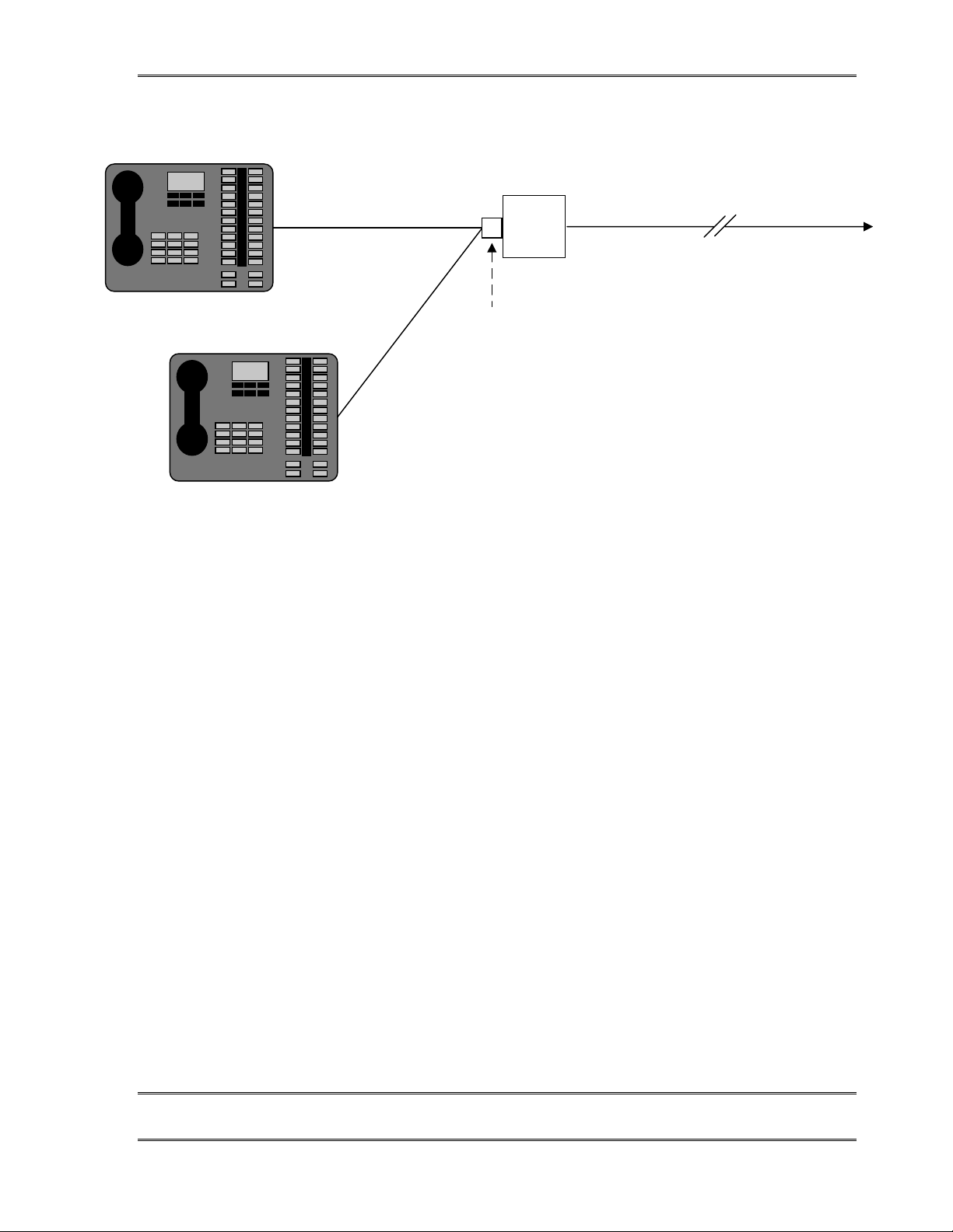
TELOS TWOX12 USER’S MANUAL
p
n
Distance "A"
Distance "B"
In the Multiple configuration one Desktop Director™ must be reconfigured to
have its termination resistors removed (see below). This unterminated
Desktop Director™ must be within 33 feet (10 meters) of the power supply
8-Pin (RJ-45)
Modular splitter
Lucent
Power
Supply
1100 feet (338 meters) maximum
To TWOx12 Deskto
Director Port
NOTES:
1) A must be less than 120 feet (37 meters)
2) B must be less than 33 feet (10 meters)
3) Desktop Director B must have terminatio
resistors removed.
Desktop Director™ Termination Resistor Settings
Desktop Directors™ are shipped with the internal termination resistors enabled. When two
Desktop Directors are used in a single port, the termination resistors on the Director closer
to the power supply will need to be disabled. To do so follow the steps below:
1. Disconnect the Desktop Director cable from the Desktop Director.
2. Remove the handset from its resting place and turn over the Director so you can
see the bottom of the unit.
3. Remove the round black cover. This can be pried off with a knife blade. Or a
miniature screwdriver may be pushed firmly under the lip and then lifted out to
pop the cap loose.
4. You will see a black rectangular transformer labeled T1. To the right of T1 locate
and remove the jumpers labeled JP1 & JP2.
These are small jumper blocks which can be lifted off with needle-nose pliers.
5. You’ll want to save the jumper blocks. You can store each of them on one of the
jumper pins.
6. Replace the access cover removed in step 3 by pushing firmly in place.
CHAPTER 2 43
INSTALLATIO N
Page 56
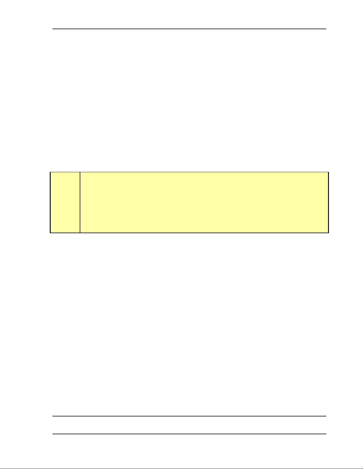
7. Reconnect the Desktop Director cable and turn the unit upright
8. Check for proper operation
Desktop Director Assembly
Wire assembly
This should be fairly self explanatory. The black “curly cord” plugs into the handset. The
other end of this cord should be plugged into the small 4 position/4 pin modular (RJ-22
style) jack near the front left of the unit. This jack is identified with a picture of a telephone
handset and is the jack closer to the front of the Director. The second jack at this location
can be used to directly connect a telephone headset and is identified with a picture of a
headset. Route these cables through the small slots to the left so they do not interfere with
the unit sitting flat on the table.
HOT TIP!
We have tested, and recommend, the Plantronics model P51- U10P "Supra Polaris noisecanceling unamplified monaural" or model P61- U10P "Supra Polaris noise- canceling
unamplified binaural " headsets for use with the Desktop Director. For the name of your
nearest Plantronics dealer contact them at 831 426- 5868 or www.plantronics.com.
h
TELOS TWOX12 USER’S MANUAL
When the headset is attached it will automatically mu te the micro phone of the hands et to
prevent extraneous noise. Disconnecting the “quick-connect” inline connector on the
headset cable will re-enable the handset microphone .
Line Designation Strip
The Desktop Director ships with several pre-cut paper “designation strips” to allow
labeling the lines of the Director. Choose one and fill out the line numbers if desired (we
suggest a “Sharpie extra fine point” or similar fine point indelible marker). Place the paper
strip on the director and then cover with the clear plastic protector, inserting the plastic tabs
in the slots on the Director to hold it in place. Should you decide to change things later,
simply lift one end of the plastic and slide out the strip.
Mounting Opti ons
The Desktop Director legs can be mounted in an alternative “upright” orientation. To do so,
remove the legs by removing the two Phillips head screws on each leg. The legs can then
be mounted in the alternative orientation using the same screws.
The Desktop Director can be mounted on a wall or other vertical surface. First remove the
legs by removing the two Phillips head screws on each leg. The unit can then be hung from
two screws on 5 inch (127 mm) centers. Care should be taken that the screws do not
protrude more than 1/8 inch (3 mm) from the mountin g surfa ce.
CHAPTER 2 44
INSTALLATIO N
Page 57

2.8 AC (mains) Power
The AC receptacle connects mains power to the unit with a standard IEC (International
Electrotechnical Committee) power cord and provides an on/off switch. The power supply
has a “universal” AC input, accepting a range from 100 to 240 VAC, 50-60 Hz. A fuse is
located inside on the power supply circuit board.
IMPORTANT!
As with any piece of modern electronic gear, it is advisable that precautions be
taken to prevent damage caused by power surges. Standard line surge protectors
can be used to offer some degree of protection. It is the user’s responsibility to
ensure protection adequate for their conditions is provided.
w
TELOS TWOX12 USER’S MANUAL
0
IN TE R NA L F U SE
UN IVERSA L POW ER INPUT
90-260VAC
e
w
WARNING!
This equipment is designed to be operated from a power source which includes a
third “grounding” connection in addition to the power leads.
Do not defeat this safety feature. In addition to creating a potentially hazardous
situation, defeating this safety ground will prevent the internal line noise filter
from functioning.
IMPORTANT SAFETY INFORMATION!
If fuse replacement is required, please note:
against fire, replace fuse only with same type and value.
DETAILED TECHNICAL INFORMATION section for information and
cautions.
For continued protection
See the
e
CHAPTER 2 45
INSTALLATIO N
Page 58

TELOS TWOX12 USER’S MANUAL
2.9 Remote Control Ports
2.9.1 Parallel Remote Control
This is a 15 pin D-Sub connector. This port provides status outputs (tallies) from the system
and allows system control using simple logic inputs or switch closures. It also has outputs
to control external equipment such as an Audio Delay or Recording device. The pin outs
and interface specifications are given here. The available functions for these inputs and
outputs are:
!
Record Control Outputs (See section 4.3.3)
!
Ring Mute In
This input will mute the ringers on all of the Desktop Directors connected to this
TWOx12.
!
User Out (Delay Dump)
This output will be asserted (low) when the User button is pressed. It will remain
asserted until that button is released.
!
Ringing Out
This output is asserted (low) whenever the system has one or more lines in the ringing
state.
PARALLEL CONTROL
For a table with the pin-outs for this connector see the next page.
CHAPTER 2 46
INSTALLATIO N
Page 59
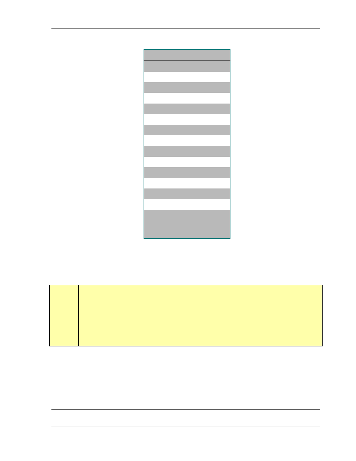
TELOS TWOX12 USER’S MANUAL
PIN FUNCTION
1 Ground
2<Reserved>
3 Record Start Out
4 Record Stop Out
5 N/C
6<Reserved>
7 Ring Mute In
8* +5 VDC (400 mA max)
9 N/C
10 User Out (Dump)
11 Ringing Out
12 N/C
13 <Reserved>
?
Inputs
14 <Reserved>
15 N/C
*
Note that the +5 volts DC on pin 8 is in parallel with pin 3 on both SAA ports. Failure to
limit combined current on these pins to 400mA could cause hardware damage or system
instability.
CURIOSITY NOTE!
The DB- designation for D- Sub connectors is from Cinch Corp’s part numbering system.
The proper Cinch designation for a 15 pin D- Sub connector is a DA- 15p (plug) or DA- 15s
(socket) not DB- 15!
Other Cinch designations for D-Sub connectors are; DE-9, DB- 25, DC-37 and DD- 50.
Our thanks going out to Mike Schweizer, for contributing this information.
This power pin is in parallel
with pin 3 of the SAA ports
• The function for each input is shown on the previous page.
CHAPTER 2 47
INSTALLATIO N
Page 60
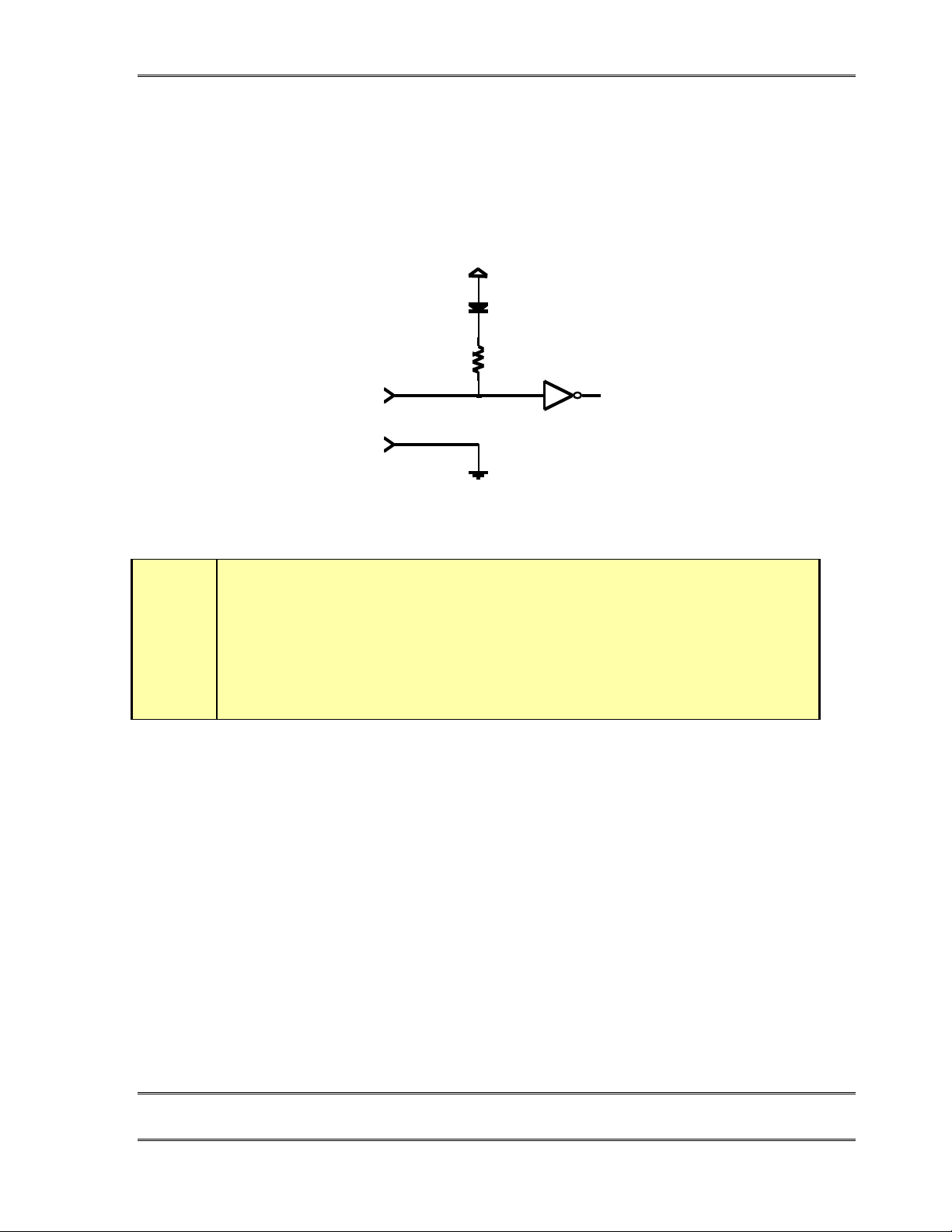
TELOS TWOX12 USER’S MANUAL
• All inputs are specially treated to accept either a voltage (up to 24 VDC), or a closure
to ground, which may be provided by switches, relays, or logic outputs. The inputs are
active low.
• A built in 1kΩ pull up resistor is provided so TTL outputs can be directly interfaced.
See below for a simplified schematic of the input circuitry.
+5V
30v max
Parallel logic input circuit
t
Outputs
DEEP TECH NOTE!
The TWO’s “universal” logic input circuit can be used with switch or relay closures,
voltage levels up to 24 Vdc, or logic outputs – either “totem- pole” or open- collector.
Outputs are open collector to ground and can sink up to 400 mA of current. Their functions
are shown on the previous page.
These will require a pull-up resistor to function with other logic inputs. Some equipment
has the pull-ups built into their control inputs – check the device’s manual to be sure. If
there is no pull-up in the interfaced equipment, you’ll have to add one. An appropriate
value is 2.2KΩ.
Current should be limited to 400ma maximum per output with total output restricted to 1
amp (200ma each output if all five will be used).
If used with a relay or LED, then tie your external power source ground to pin 1 (or use the
5 VDC power supplied on pin 8 and run this power source through your device, with a
resistor in series to limit max imu m cur ren t to 400 ma.
For additional information refer to sec tio n 7.3.3.
CHAPTER 2 48
INSTALLATIO N
Page 61
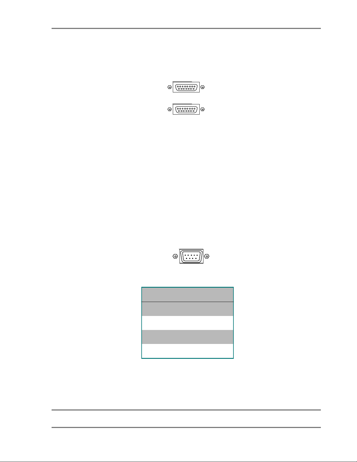
TELOS TWOX12 USER’S MANUAL
2.9.2 Special Auxiliary Access ports
These ports are unimplemented and are reserved for future use.
The input and output electrical characteristics are the same as the general purpose inputs
and outputs, see section 2.9.1. Note that the +5 volts DC on pin 3 has both SAA ports in
parallel with pin 8 on the Parallel remote control port. Failure to limit the combined current
on these pins to 400mA could cause hardware damage or system instability.
2.9.3 RS-232 Serial Remote Control
SAA 1
SAA 2
The RS-232 serial port supports asynchronous data, 8 bits, no parity, 2 stop bits, 240038,400 bits per second. The Clear to Send (CTS) handshake signal is provided, however
any handshake signals from the external equipment are ignored. This port is primarily for
troubleshooting purposes and should be used as directed by Telos Customer Support.
Connector is a 9 pin D-Sub connector with the following pin-out:
RS-232
DCE
PIN FUNCTION
2 Rx (TWO to Computer)
3 Tx (Computer to TWO)
5 Ground
8 CTS (TWO to Computer)
Using a 9 pin D-Sub connector, this is an RS-232 serial port using the standard PC-style format,
configured as if it were a modem.
CHAPTER 2 49
INSTALLATIO N
Page 62
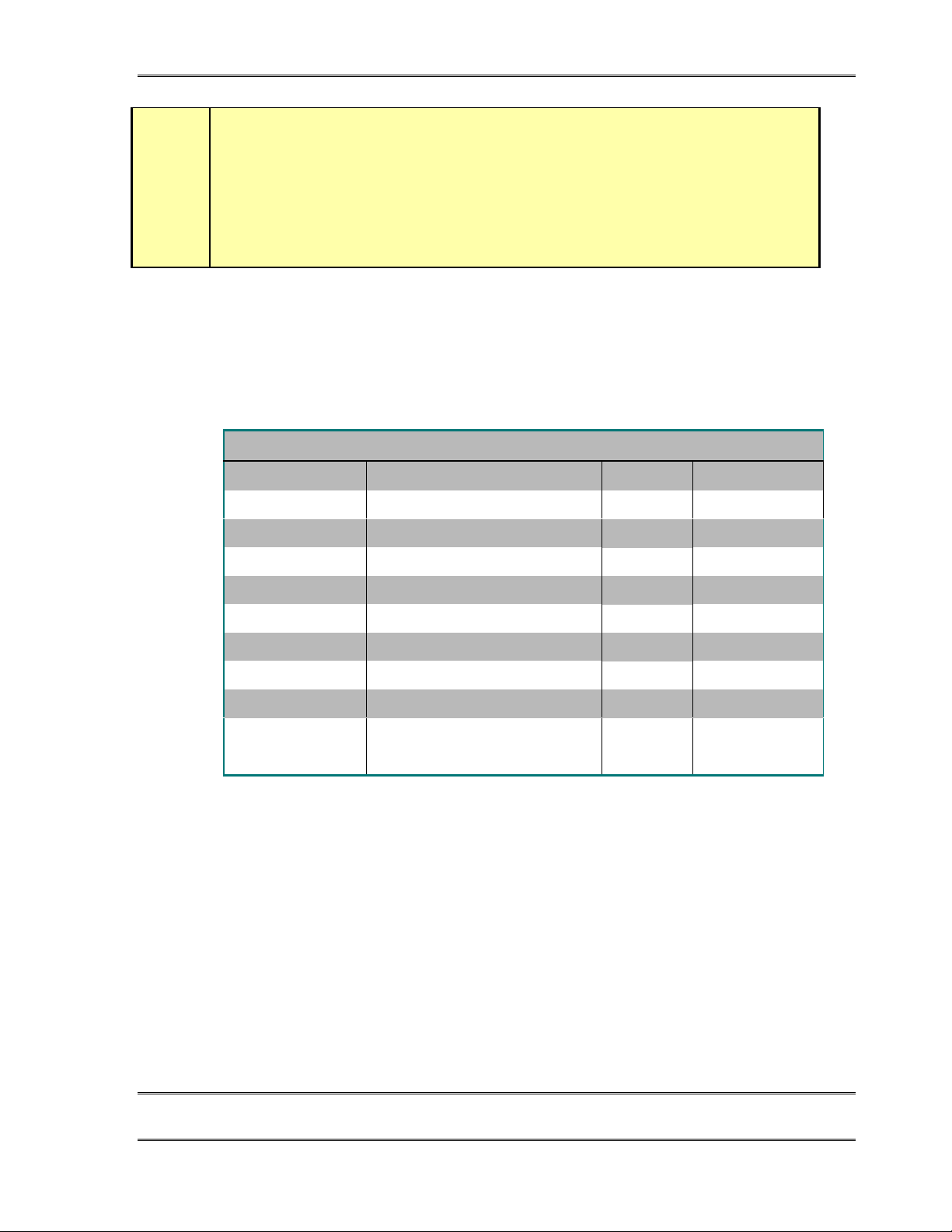
h
TELOS TWOX12 USER’S MANUAL
HOT TIP!
This port is configured for DCE (Data Communications Equipment) as opposed to
DTE (Data Terminal Equipment) operation – meaning that it looks like a modem, not
a computer. Therefore, a “reversing” or “null-modem” cable is required to connect to a
modem, while a standard “straight through” cable is required to interface to a
computer. Cables may be easily fabricated or may be obtained from a computer store.
The following tables show the recommended cable configuration for connecting the Telos
TWOx12 to 9 pin and 25 pin DTE (computer) serial ports.
CABLE PIN OUT 9-PIN
Computer (DTE) Description Direction Telos TWO
1 *Data Carrier Detect (DCD)
2 Receive Data (RD)
3 Transmit Data (TD)
4 *Data Terminal Ready (DTR)
5 Signal Ground (SG) 5
6 *Data Set Ready (DSR)
7 *Request to Send (RTS)
8 *Clear to Send (CTS)
9 *Ring Indicator (RI)
*Optional connection, may not be required
3
3
4
4
3
4
3
3
8
2
3
Not used
8
Not used
8
Not used
CHAPTER 2 50
INSTALLATIO N
Page 63
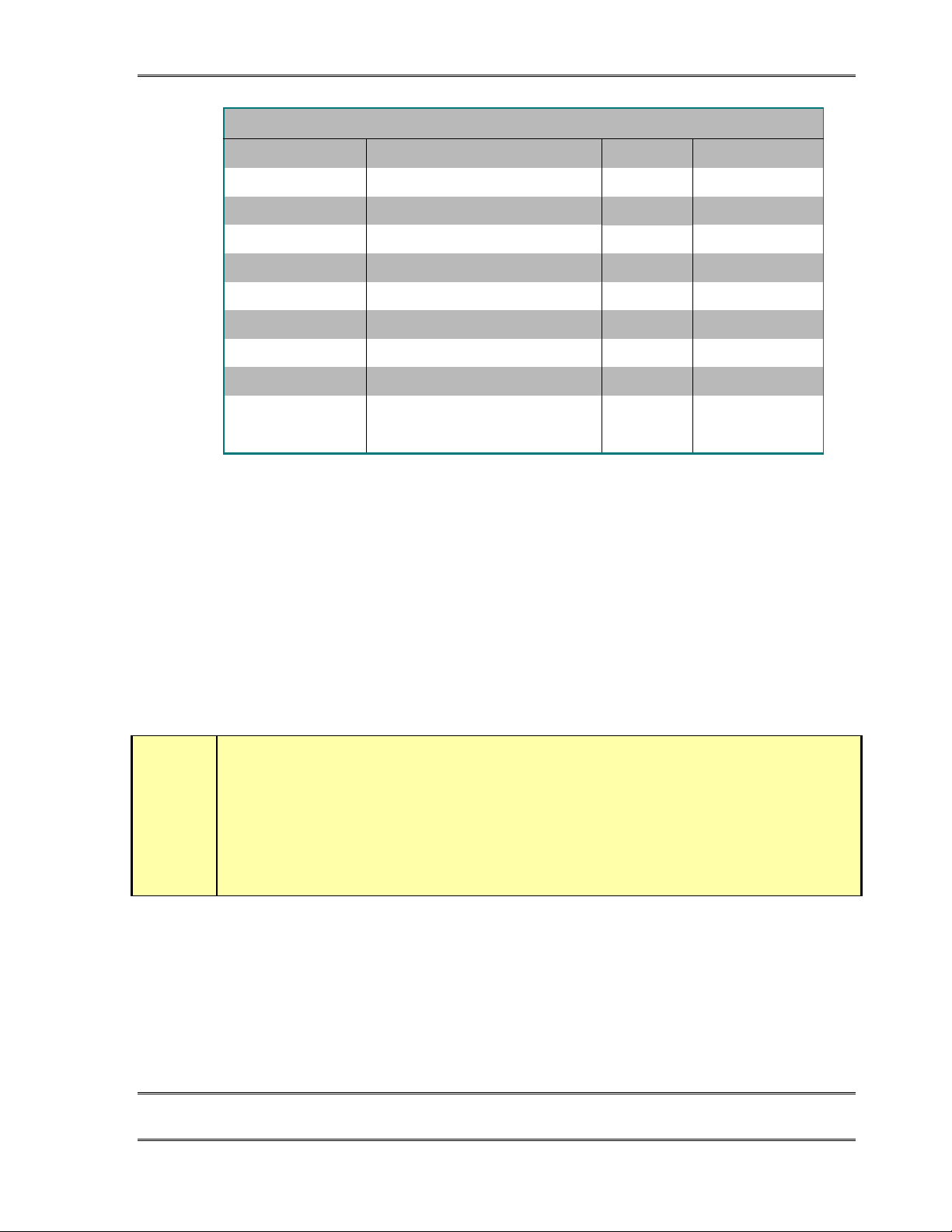
TELOS TWOX12 USER’S MANUAL
CABLE PIN OUT 25-PIN
Computer (DTE) Description Direction Telos TWO
2 Transmit Data (TD)
3 Receive Data (RD)
4 *Request to Send (RTS)
5 *Clear to Send (CTS)
6 *Data Set Ready (DSR)
7 Signal Ground (SG)
8 *Data Carrier Detect (DCD)
20 *Data Terminal Ready (DTR)
22 *Ring Indicator (RI)
*Optional connection, may not be required
2.9.4 Ethernet Remote Control
Ethernet 10Base-T connector for connection to an Ethernet Local Area Network. This
allows the TWOx12 to communicate directly to Telos Assistant Producer 2.0 clients
running on your network. The TWOx12 need not be connected to a host computer running
server software as required with older Telos Telephone Interface products (in fact Telserv
is not required). In addition, the system can be controlled using a Telnet connection using
this port. Section 7.4.1 has a list of commands which can be sent over the RS-232 or
Ethernet port to control the system.
4
3
4
3
3
3
4
3
3
2
Not used
8
8
8
Not used
Not used
IMPORTANT TIP!
Assistant Producer version 2.0 or later is required for use with the TWOx12.
w
If you will be using call screen software we recommend that a separate LAN be used
exclusively for the Talk Show System. This will avoid sluggish responses caused by large
amounts of other network traffic.
This port is also used for software upgrades over the Internet. For details see section 7.3.3.
This is an industry standard 10Base-T Ethernet connector on the usual 8 pin miniature
modular (RJ-45 style) jack.
CHAPTER 2 51
INSTALLATIO N
Page 64

TELOS TWOX12 USER’S MANUAL
The 10Base-T connector has two integral LED indicators which can be helpful if problems
are suspected.
The green “Link” LED indicates the presence of a live physical connection to a working
Ethernet hub (or other device). If the green indicator does not light you should check your
network wiring. Absence of the link light could also indicate a hardware failure of the
TWOx12.
The amber “Activity” LED indicates network activity on this segment of the network.
Depending on network activity this indicator may only illuminate occasionally; flickering
of this light is normal.
CHAPTER 2 52
INSTALLATIO N
Page 65

TELOS TWOX12 USER’S MANUAL
3 Getting Up & Going –System Configuration
3.1 System programming
The checklist on the next few pages is intended to help you collect the information you will
need about your lines and enter it into the TWOx12. The first half should be completed
with the relevant information about your lines, and the second half then followed to
program the lines themselves.
Before proceeding through the steps outline d in this sect ion ple ase per form the initial
installation as described in section 2. See the Installation Checklist in section 2.2
CHAPTER 3 53
GETTING UP & GOING – SYSTEM CONFIGURATION
Page 66

TELOS TWOX12 USER’S MANUAL
System Programming Checklist (Copy this checklist and u se it to help or ganize your installation)
Part I-Line Information
For each interface slot (A, B, C, & D), there will be either an ISDN interface or a POTS
(analog line) interface present (see sections 2.5.1, 2.5.3, & 2.5.4 for illustrations).
There are 4 channels on an ISDN interface, called Top1, Top2, Bot1, & Bot2. The ISDN
BRI connected to the top jack has channels Top1 & Top2 while the ISDN BRI connected to
the lower jack has channels Bot1 & Bot2. Each of these channels will normally have its
own phone number (called a “DN” in USA and Canada or a “MSN” in areas using EuroISDN).
There are only 3 channels on a POTS interface, called 1, 2, & 3. So a POTS interface in
Slot A would have 3 channels called 1, 2, & 3. Each of these channels will have its own
telephone number.
Please enter the information for each interface slot below. For ISDN lines enter the DN or
MSN in the space for Telephone Number. SPIDs are only needed with certain ISDN types
in the USA & Canada, see sections 3.3 and 7.3.2 for more information.
Once you have completed these pages the telephone numbers indicate under “Telephone
#/DN/MSN” from top to bottom will correspond to your Lines 1 through 12 of the system.
SLOT A
❏
POTS
##
(top)
❏
(middle)
❏
(bottom)❏(bottom)
❏
(Not present)❏(bottom)
❏
❏
❏
ISDN
(top)
(top)
Telephone #/DN/MSN SPIDs (ISDN only-USA & Canada)
(A Top1) (A Top1)
(A Top2) (A Top2)
(A Bot1) (A Bot1)
(A Bot2) (A Bot2)
SLOT B
❏
POTS
##
(top)
❏
(middle)
❏
(bottom)❏(bottom)
❏
❏
❏
❏
ISDN
(top)
(top)
Telephone #/DN/MSN SPIDs (ISDN only-USA & Canada)
(B Top1) (B Top1)
(B Top2) (B Top2)
(B Bot1)_ (B Bot1)
(Not present)❏(bottom)
CHAPTER 3 54
(B Bot2) (B Bot2)
GETTING UP & GOING – SYSTEM CONFIGURATION
Page 67
TELOS TWOX12 USER’S MANUAL
SLOT C
❏
POTS
##
(top)
❏
(middle)
❏
(bottom)❏(bottom)
❏
(Not present)❏(bottom)
❏
❏
❏
ISDN
(top)
(top)
Telephone #/DN/MSN SPID (ISDN only-USA & Canada)
(C Top1) (C Top1)
(C Top2) (C Top2)
(C Bot1) (C Bot1)
(C Bot2) (C Bot2)
SLOT D
❏
POTS
##
(top)
❏
(middle)
❏
(bottom)❏(bottom)
❏
❏
❏
❏
ISDN
(top)
(top)
Telephone #/DN/MSN SPIDs (ISDN only-USA & Canada)
(D Top1) (D Top1)
(D Top2) (D Top2)
(D Bot1) (D Bot1)
(Not present)❏(bottom)
(D Bot2) (D Bot2)
System Programming Checklist
Part II- Programming
❏ Set
Input Source
for
Digital
(AES/EBU) or
Analog
. See section 7.3.1
❏❏Does the system use any ISDN circuits?
NY
#$❏ Are you familiar with ISDN? If not, read sections 2.3 & 2.4
❏ Configure ISDN. See section 3.3
❏ Confirm ISDN is working. See section 3.5
❏ Set Input & Output levels. See section 3.6
CHAPTER 3 55
GETTING UP & GOING – SYSTEM CONFIGURATION
Page 68

TELOS TWOX12 USER’S MANUAL
❏ Enter TCP/IP addresses if used. See section 7.3.3
❏ Read up on Desktop Director Operation. See section 4.
❏ Set up hybrid audio options. See section 7.3.1
CHAPTER 3 56
GETTING UP & GOING – SYSTEM CONFIGURATION
Page 69

3.2 Initial Installation
We presume you have at least glanced through the material in chapter 2 and gone through
the steps shown in the Installation Checklist (section 2.2). By now you should have your
console mix-minus(es) connected to the TWOx12, and the TWOx12’s outputs connected to
faders on your console (mixing desk). The TWOx12 should be connected to the ISDN (or
POTS) telephone circuits and have power and be turned on. The LCD screen should be on
and you should see the default screen similar to the one illustrated below.
TELOS TWOX12 USER’S MANUAL
TWOx12
V1.0
TELOS SYSTEMS yyyy-mm-dd
3.3 ISDN Setup (if you ordered an analog TWOx12 see section 3 .4)
We need to configure your TWOx12 for your telephone circuits. First we will need to
determine circuit will represent each “line” of the system. You should fill out the Line
information of the System Programming Checklist (see section 3.1) now, before
proceeding. Recall that each BRI has 2 channels, each of which will appear to be a “line” to
the users on the Desktop Director™. And each analog (POTS) circuit will appear as a
“line” as well. The diagrams in sections 2.5.1, 2.5.3, & 2.5.4 show the relationship for
various possible TWOx12 configurations.
The following are simple step-by-step instructions. For additional information and
numerous tips on ISDN see section 7.3.2. Again, this will depend on where you are located:
ISDN setup for outside the USA & Canada begins on the next page. Users in the USA &
Canada should skip ahead 2 pages.
CHAPTER 3 57
GETTING UP & GOING – SYSTEM CONFIGURATION
Page 70
TELOS TWOX12 USER’S MANUAL
Worldwide ISDN Setup (
Worldwide ISDN Setup (outside USA & Canada): (Users outside the USA & Ca nada
Worldwide ISDN Setup (Worldwide ISDN Setup (
should skip this section)
• Press the TEL button
You will see a screen which looks like the following:
Telco Settings
Audio Settings
Telco Natl.I-1
Slot A
Slot B $
Slot C $
• Make sure the dark cursor bar is over Telco as shown (if not use the 5 & 6 keys to
move the cursor) and press the Select button.
• Press the 5 button until ETS300 (or other appr opr ia te proto col ) is shown and press the
Select button again to confirm.
• Scroll down using the 6 button until you have highlighted SLOT A with the dark
cursor bar.
• Press the Select button. You will now see a screen which looks like:
Audio Settings
Slot-A ISDN
↵
$
Top SPID1
Top SPID2
TopDN/MSN1
• Scroll down using the 6 button until you have highlighted TopDN/MSN1 and press
the Select button. Enter your first MSN for the ISDN circuit in the top jack of slot A
using the numeric keypad. If you do not have a MSN you must ewnter a unique 3 digit
number here. If a number had been previously entered you may delete it one character
at a time by using the 5 button. Push Select again to confirm.
CHAPTER 3 58
GETTING UP & GOING – SYSTEM CONFIGURATION
Page 71
TELOS TWOX12 USER’S MANUAL
• Scroll down to TopDN/MSN2 and repeat the previous step, entering the second MSN
for the ISDN circuit in the top jack of slot A. If your line does not have MSNs you
must enter a unique 3 digit number here. Push Select to confirm.
• Scroll down to BotDN/MSN1 using the 6 button and repeat the previous step, entering
the first MSN for the ISDN circuit in the bottom jack of slot A. Push Select to
confirm.
• Scroll down to BotDN/MSN2 and repeat the previous step, entering the second MSN
for the ISDN circuit in the bottom jack of slot A. Push Select to confirm.
• Scroll up to the ↵ using the 5 button and press the Select button.
• Repeat the steps above to enter your MSNs for slots B and C, if needed.
• Power the unit off and then back on.
USA & Canada ISDN Setup
USA & Canada ISDN Setup (users outside the USA & Canada sho uld see the previous section):
USA & Canada ISDN Setup USA & Canada ISDN Setup
• Press the TEL button
You will see a screen which looks like the following:
w
Telco Settings
Audio Settings
Telco Natl.I-1
Slot A ISDN $
Slot B ISDN
Slot C ISDN
• Make sure the dark cursor bar is over Telco as shown (if not, use the 5 & 6 keys to
move the cursor) and press the Select button.
• Press the 5 or 6 button until the appropriate protocol is shown (see tips below) and
press the Select button again to confirm.
IMPORTANT!
Each ISDN Line has a certain ISDN protocol (or “switch type”) which the phone
company should have given you. By far the most common protocols in the USA &
Canada are National ISDN- 1 & National ISDN- 2 in which case you should set the
Telco setting to
If you do not know what protocol your line is configured for, try
does not work see section 7.3.2 for hints on how to guess your protocol.
Natl.I- 1
.
$
$
Natl.I- 1
first. If that
CHAPTER 3 59
GETTING UP & GOING – SYSTEM CONFIGURATION
Page 72
w
TELOS TWOX12 USER’S MANUAL
• Scroll down using the 6 button until SLOT A is highlighted with the dark bar.
• Press the Select button. You will now see a screen which looks like:
Slot-A ISDN
Audio Settings
↵
Top SPID1
Top SPID2
TopDN/MSN1
IMPORTANT TIP!
You will be entering 2 SPIDs and 2 Directory Numbers (DNs) for EACH of your ISDN BRI
circuits. In the menus that follow we use the following nomenclature for each slot in the
TWOx12. Please take care to get the right SPID and DN in the correct entry field as ISDN
requires this information to operate.
TOP BRI, 1st SPID & DN = TopSPID1 & TopDN/MSN1
TOP BRI, 2nd SPID & DN = TopSPID2 & TopDN/MSN2
BOTTOM BRI, 1st SPID & DN = BotSPID1 & BotDN1
BOTTOM BRI, 2nd SPID & DN = BotSPID2 & BotDN2
• Scroll down using the 6 button until you have highlighted TopSPID1 and enter your
the first SPID for the ISDN circuit in the top jack of slot A using the numeric keypad.
If a number had been previously entered you can delete it one character at a time using
the 5 button. Push Select again to confirm.
• Scroll down using the 6 button until you have highlighted TopSPID2 and enter the
second SPID for the ISDN circuit in the top jack of slot A using the numeric keypad.
If a number had been previously entered you can delete it one character at a time using
the 5 button. Push Select again to confirm.
• Scroll down using the 6 button until you have highlighted TopDN/MSN1 and enter
you’re first DN (Directory Number) for the ISDN circui t in the top jack of slot A
using the numeric keypad. Push Select again to confirm.
• Scroll down to TopDN/MSN2 and repeat the previous step, entering the second DN for
the ISDN circuit in the top jack of slot A. Push Select to confirm.
• Scroll down to BotSPID1 and repeat the previous step, entering the first SPID for the
ISDN circuit in the bottom jack of slot A. Push Select to confirm.
CHAPTER 3 60
GETTING UP & GOING – SYSTEM CONFIGURATION
Page 73
i
TELOS TWOX12 USER’S MANUAL
• Scroll down to SPID2 and repeat the previous step, entering the second SPID for the
ISDN circuit in the bottom jack of slot A. Push Select to confirm.
• Scroll down to BotDN/MSN1 and repeat the previous step, entering the first DN for the
ISDN circuit in the bottom jack of slot A. Push Select to confirm.
• Scroll down to BotDN/MSN2 and repeat the previous step, entering the second MSN
for the ISDN circuit in the bottom jack of slot A. Push Select to confirm.
• Scroll up to the ↵ using the 5 button and press the Select button.
• Repeat the steps above to enter your SPIDs & DNs for slots B and C.
• Power the unit off and then back on.
ISDN TIP!
1. Incorrectly entered SPIDs are the most common problem users in the USA &
Canada have placing ISDN calls. Compare the SPIDs you have entered with the
SPIDs provided to you on by the phone company to be certain that you have entered
them correctly. Do not add anything to your SPIDs.
2. Note that there are no hyphens, dashes (- ), or spaces in SPIDs so the system will
not allow you to enter any non- numeric characters. If your installer has included
them in the SPID, ignore them.
3. For a list of known working SPIDs by Telephone Company see the appendix.
4. See section 7.3.2 for numerous tips about SPIDs and ISDN protocol settings.
5. If you have any questions about your SPIDs, call your phone company.
6. If you have PTP (AT&T Point- to- Point) or ETS300 (Euro- ISDN) Telco mode, you
should not enter anything in the SPID fields.
HOT TIP!
The Directory Numbers or DNs (sometimes called Listed Directory Numbers or LDNs)
are your 7- digit phone number as would be found in the Telephone Directory. They
normally do not include the area code.
h
IMPORTANT!
Each directory number (DN) will correspond to one SPID. You must enter them to
reflect this relationship. The DN corresponding to SPID1 must be entered as DN1
while the DN corresponding to SPID2 must be entered as DN2.
If you experience problems only with incoming calls check your DNs.
w
CHAPTER 3 61
GETTING UP & GOING – SYSTEM CONFIGURATION
Page 74
TELOS TWOX12 USER’S MANUAL
3.4 Analog phone line setup (If you ordered an ISDN TWOx12 see section 3.3)
You can identify that your TWOx12 is equipped with POTS (analog) telephone lines
by examining the rear panel. If four interface cards with three RJ-11 style connectors
each are present (in slots A, B, C, & D), then the unit supports analog operation.
No configuration is necessary when POTS lines are used. In this case the Tel menu will
look as follows:
Telco Settings
Audio Settings
Telco Natl.I-1
Slot A POTS
Slot B POTS
Slot C POTS
If you have a mixed system, you will see some slots labeled in this menu as “ISDN” rather
than “POTS”. You’ll need to follow the steps in section 3.3 to configure those slots.
3.5 Is the ISDN working?
Successful initialization of a line will be indicated by the idle line state on the Desktop
Director. The idle line state looks as follows:
Press the Status button then press the 6 button. You should see a screen that says Slot A -
Status at the top. If you do not see this screen don’t panic, just repeatedly press the 5or 6
button until you see this screen.
If you do not see “READY” for each ISDN channel on the Slot Status screens try turning
the unit off and then back on again. If you still do not get READY you may need to go back
to section 3.3 and check both your ISDN settings and set-up information. If the information
there does not help, there is in-depth troubleshooting information in section 8.
CHAPTER 3 62
GETTING UP & GOING – SYSTEM CONFIGURATION
Page 75
w
TELOS TWOX12 USER’S MANUAL
IMPORTANT!
Users in the USA & Canada should see READY status for each line whenever the
system is idle. On certain ETS- 300 ISDN lines the lines may go from READY to
DEACTIVATED after an idle period. This is no cause for alarm and you can proceed
with the following steps.
Once you see “READY ” for each channel on the appropriate Slot - Status screens we can
proceed to make a call and verify that the ISDN lines are, in fact, working. We will start out
with the simplest case, a call from your “line 1” to your “line 2”as follows:
• Confirm that the Desktop Director™ you will be using has power and says “Talent” at
the top of the screen. If it says “Producer” follow the directions in section 4.4.2 to
change this Director to “Talent” mode.
• First pick up the handset and push each line button in the left row listening for dial
tone. If this does not happen see section 8 for information on troubleshooting your
problem.
• Next, pick up the handset and press the left Line 1 button to select that line for dialing.
You should now hear dial tone on the handset.
• Enter the phone number for line 2 using the numeric keypad.
• You should now hear a ringing sound and see the ringing Status Symbol (an
expanding square) on Line 2. Push the right Line 2 button to answer this call. The
→ Icon should appear for line one.
• Drop this test call by pressing the right Drop button
• If this happens, your “lines” 1 and 2 are working (if you are using ISDN BRI circuits
you have now tested the first BRI). If this does not happen see section 8 for information
on troubleshooting your problem.
• Now repeat this test by calling from “Line 2” to “Line 3”, “Line 3” to “Line 4” etc
until all lines have been tested.
• If you do not plan on proceeding to the next section and setting your levels now, be
sure to push the Drop button
HOT TIP!
Many phone lines have per- minute usage charges. Don’t forget to drop the call once
your testing and configuration are complete.
after the final call.
.
h
CHAPTER 3 63
GETTING UP & GOING – SYSTEM CONFIGURATION
Page 76
3.6 Levels, Levels, Levels
Ok, we assume that you just made a call to yourself in section 3.5, above (if not, please
follow those steps now). Congratulations, you just have some tweaking to do and your
basic installation & configuration will be complete!
• Bring up some audio on the console (mixing desk). Spoken word is best, as it tends
to have a lot of dynamics, but music will work. While tone will work for the coarse
adjustments (set it to the red-green boundary point), we do not recommend using it
for final adjustments. Adjust the levels on the board to the levels set by your typical
operator! NOTE: If your board operators typically run “into the red”, you should
do the same! For now make sure the faders for both of the hybrids are TURNED
OFF.
IMPORTANT!
If your board operators typically run “in the red”, you should do the same!
TELOS TWOX12 USER’S MANUAL
w
• Set the left LED meter to STUDIO IN, if necessary, by pressing the button located
on this meter. You should see the audio from your console on these meters (the
send-to-hybrid 1 audio will be on the LED bargraph labeled 1 and the send-tohybrid 2 will be on the LED bargraph labeled 2.
• Observe the levels on these two meters. You will note that the highest peak level
reading is represented by a “floating” LED that persists near the top of the meter.
Since our goal is to set the levels so that peak levels do not hit 0dBfs, this peak
reading is what we need to watch. Section 7.1 has more information on the
TWOx12’s metering.
• First set the Input Gain selection found in the Audio Settings menu to a nominal
level close to that used in your facility (i.e. –7, 0, +4, or +8 dBu). This control sets
the level for both inputs. If the inputs are not reading identically, you will need to
adjust them at the output of the console. Note that the lower this sele ction is set,
the higher the levels on the unit’s meters, as this setting represents nominal input
level.
• Next adjust your console output (mixing desk) level (for the mix-minus) if
necessary. We suggest that you keep the peak level below a -4 to -6 reading, this
will allow some room for error on the part of your operators. If you are using a tone
to set levels you may need to set them considerably lower.
CHAPTER 3 64
GETTING UP & GOING – SYSTEM CONFIGURATION
Page 77
h
TELOS TWOX12 USER’S MANUAL
Hot Tip!
If you have already determined the clipping point of your console, or are using AES/EBU,
you can just select a level setting using the chart in section 7.3.1. Recall that the system
allows for 13dB of headroom, regardless of the Input Gain setting, so you should select a
setting that is 13dB below the clipping point of your board.
Of course if you already know the clipping point of your console you probably don’t need
this advice!
• Set the right meter to STUDIO OUT, if necessary, by pressing the button located on
the meter. You should see the audio from the phone line on these LED bargraphs
(since we are connected hybrid 1 to hybrid 2 the audio will be reversed. The audio
sent to hybrid 1 will return on hybrid 2 and will be on the LED bargraph labeled 2
and the audio sent to hybrid 2 will return on hybrid 1 and will be on the LED
bargraph labeled 1. Bring up the fader for hybrid 1 on your console.
• Adjust the TWOx12’s Output Gain adjustment found in the Audio Settings screen.
This sets the level for both outputs. Once you have set hybrid 1 pull that fader
down and bring up the fader for hybrid 2. If the sources are not reading identically
you will need to adjust the input trim of the console on one of the two input
channels.
• You can drop the call you made in the previous section. Push the right Drop
button .
3.7 Time to test it out!
Ok, you made it! Another hour and you can go home for the day! First we will check that
the mix-minus for each hybrid is correct. Then we will make a test call.
• Confirm that the Desktop Director you will be using has power and says “Talent”
at the top of the screen. If it says “Producer” follow the directions in section 4.1.3
to change this Director to “Talent” mode.
• Next, pick up the handset and press the left Line 1 button to select that line for
dialing. You should now hear dial tone on the handset.
• Enter the phone number for a telephone line which has audio present, using the dial
pad (calling either the time or weather service works well for this).
• Press the left Line 1 button and hang up the handset to place the call on hybrid 1.
• Bring up hybrid 1 on the console. You should hear the audio from the phone line.
• Look at the left meter on the TWOx12 and verify that this audio is not present on
the “1” LED bargraph. If this audio is present here you are not feeding hybrid 1 a
mix-minus and you must fix this problem before you proceed.
CHAPTER 3 65
GETTING UP & GOING – SYSTEM CONFIGURATION
Page 78
w
TELOS TWOX12 USER’S MANUAL
IMPORTANT!
If you are using one of the routing schemes that requires only a single mix- minus you
should
that case you can skip the next test.
See section 7.3.1 for detailed information about the TWOx12’s routing options.
Now we will verify the second mix-minus.
• Press right Line 2 button to move the call made above to hybrid 2.
• Bring up hybrid 2 on the console. You will hear the audio from the phone line.
• Look at the left meter on the TWOx12 and verify that this audio is not present on
have seen audio on either the “1” or “2” bargraphs in the previous test. In
not
the “2” LED bargraph. If this audio is present here you are not feeding hybrid 2 a
mix-minus and you must fix this problem before you proceed.
• Drop the call by pushing the Drop button
Ok, now we just need to test the system as whole. We suggest calling your spouse or
partner and reporting that you will be home for dinner after all!
1. Confirm that the Desktop Director you will be using has power and says “Talent”
at the top of the screen. If it says “Producer” follow the directions in section 4.1.3
to change this Director to “Talent” mode.
2. Press the left Line 1 button to select that line for dialing. You should now hear dial
tone through the console (mixing desk).
3. Enter the phone number for the line you wish to call.
4. Bring up hybrid 1 on the console. You will hear the audio from the phone line.
5. Put on some headphones, bring up the microphone, and greet the party at the far
end.
6. Your voice should sound normal in your headphones, without any tinny or hollow
artifacts, and the caller should sound clear.
7. Move the call to Hybrid 2 by pressing the right Line 1.
8. Repeat steps 4 through 6 using hybrid 2.
.
CHAPTER 3 66
GETTING UP & GOING – SYSTEM CONFIGURATION
Page 79

What now?
Your basic installation is complete. Next you will want to look over other sections of this
manual to familiarize yourself with the system and decide how to set up the following
parameters:
TELOS TWOX12 USER’S MANUAL
• Desktop Director Setup See section 4
• Desktop Director Operation (Talent mode) See section 6
• Desktop Director Operation (Producer Mode) See section 5
• Receive EQ, AGC & Noise Gate See section 7.5
• Duplex Level (caller ducking) See section 7.5
• Feedback Control (when using open speakers) See section 7.5
• Send EQ, AGC See section 7.5
• Internal Audio Routing See section 7.3.1
CHAPTER 3 67
GETTING UP & GOING – SYSTEM CONFIGURATION
Page 80

TELOS TWOX12 USER’S MANUAL
This page is intentionally left devoid of useful information, except, of course, this message!
CHAPTER 3 68
GETTING UP & GOING – SYSTEM CONFIGURATION
Page 81
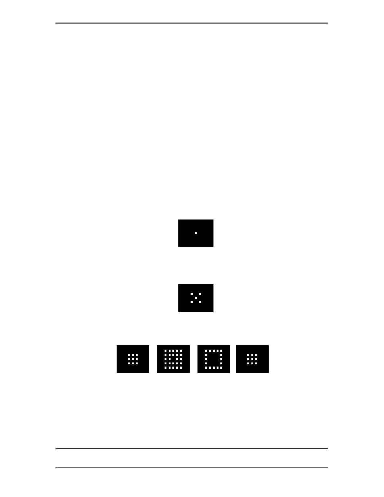
TELOS TWOX12 USER’S MANUAL
4 Desktop Director™- General operation
4.1 General Description
The Telos Desktop Director™ acts as a studio telephone while at the same time acts
as a control surface for putting lines on either of the Telos TWOx12’s built-in
hybrids. The Desktop Director™ has two modes of operation – Producer (Screener)
mode and Talent mode. This section gives general information while sections 5 and 6
give complete details on using the TWOx12 and Desktop Director™ in Producer and
Talent modes, respectively.
Those sections should be duplicated and distributed for your staff to read.
4.2 Status Symbol™ Icons & What They Mean
The Desktop Director™ breaks new ground in broadcast telephone control surfaces
with the use of easy to understand Status Symbol™ Icons displayed on the LCD
matrixes located between the two rows of line selectors. In most cases the meaning of
each symbol is easily and effortless understood without study. However, to be
complete, here is what each sequence means.
This line is on-hook ready for incoming or outgoing calls (Idle)
This line is in use by another studio
Line is ringing
CHAPTER 4 69
DESKTOP DIRECTOR – GENERAL OPERATION
Page 82
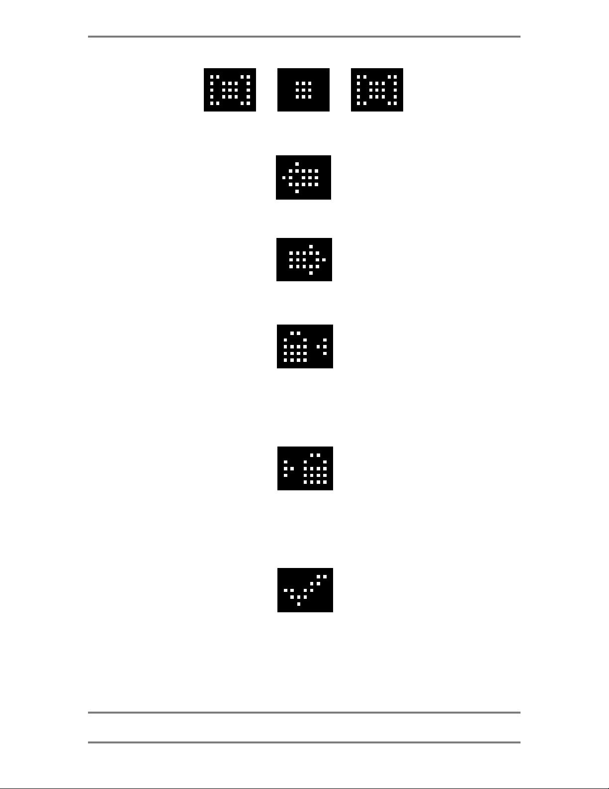
TELOS TWOX12 USER’S MANUAL
Call is on hold
Call is On-Air – Caller 1 Fader
Call is On-Air – Caller 2 Fader
Call is On-Air & Locked – Caller 1 Fader.
Call is in locked mode and cannot be dropped or placed on hold. To unlock, push button to
the left of this ICON.
Call is On-Air & Locked – Caller 2 Fader.
Call is in locked mode and cannot be dropped or placed on hold. To unlock, push the
button to the Right of this ICON.
Call is on hold and has been screened.
CHAPTER 4 70
DESKTOP DIRECTOR – GENERAL OPERATION
Page 83
TELOS TWOX12 USER’S MANUAL
Call is on hold, has been screened, and is Next.
Press Next button to put this line On-Air
Busy All Mode.
Press X Button to cancel
4.3 Buttons
The functions of most of the buttons are self evident. Again, we have used easy to
understand symbols wherever possible. A brief explanations of the buttons follows:
Handset Mode.
Call is on the handset
Speakerphone Mode.
Call is on the speakerphone
Line is not operational
CHAPTER 4 71
DESKTOP DIRECTOR – GENERAL OPERATION
Page 84
IMPORTANT!
Since certain functions work differently in “
important that your staff understand that there are two modes, and how to switch
between them. This is covered later in this section (see menu navigation) and again
in sections 5 and 6.
w
4.3.1 Line Control Buttons
Line buttons-
These work differently depending if the Desktop Director™ is in Talent or Producer
mode.
In Talent mode each line has 2 buttons, the left row for Caller 1 (or whatever you
choose to label the fader for hybrid 1) and right row called Caller 2. Pressing a line
button places the caller on that line on-air on the corresponding hybrid.
Pressing a Line button when caller is already on-air locks the caller. To unlock press
that Line button a third time.
TELOS TWOX12 USER’S MANUAL
Talent”
versus “
Producer”
mode it is
If the handset is picked up, or the LED next to the Handfree button is illuminated,
the Left row of buttons will control the line to be used on the telephone. The right
row of buttons will continue to control the caller 2 hybrid as usual. To place a caller
currently on the handset on the air, press either the left (caller 1 hybrid) or right
(caller 2 hybrid).
In Producer mode the left row of buttons is used to answer calls on the handset (or
headset). The right row of buttons is used to select which call is “next” when the
talent press the next button..
Hold & Drop
(Hold) and (Drop) - You know what these do! In Talent mode these affect
only the corresponding bank of buttons above them. A locked line will not be
affected unless you unlock it first (by pushing the corresponding LINE button). All
unlocked lines in that column will be dropped.
In Producer mode the left hold button is normal hold while the right hold button
places a caller on “screened hold”. For more details on how screened hold works see
the section on the Next button, below. This right-hand hold button may be replaced
by with a keycap labeled with a check mark
will be used primarily for screening.
Next
if the Desktop Director in question
(Next) button- This button works differently in Producer versus Talent mode.
CHAPTER 4 72
DESKTOP DIRECTOR – GENERAL OPERATION
Page 85
TELOS TWOX12 USER’S MANUAL
In Talent mode this button will direct the call designated by the screener as NEXT to
Caller 1 hybrid. If no call is currently designated NEXT the call which has been on
Screened Hold the longest will be directed to the Caller 1 hybrid. If a screener is not
used, the line which has been ringing longest will be selected instead. If no line is
ringing, the line on hold the longest will be selected.
Note that if the handset is off-hook the caller will be directed to the handset, using the
same priorities outlined above.
In Producer mode this button will select the line which has been ringing longest. If
no line is ringing, it selects the line that has been on (standard) hold longest.
Busy All
(Busy All) - Pressing this key will clear all lines with the only exceptions being
lines on-air, on the handset and lines on hold. Unlocked lines on-air, lines on hold,
and lines on screened hold will be dropped. Those lines will then be blocked from
accepting any calls (in most cases the caller will get a busy signal, but this will not
always be true depending on your configuration) and the Busy All Status Symbol™
will be displayed.
Pressing
configurations callers attempting to call while you are in the Busy All state will hear
ringing. In that case the system will answer and drop those callers when you cancel
busy all mode).
HOT TIP!
As you may know, there have been several lawsuits regarding to the “fairness” of radio
contests. By consistently activating the Busy All feature before announcing a contest
your staff will reduce the liability for the station.
again will clear the lines and allow incoming calls (in some
h
4.3.2 Telephone Mode Buttons
Dial pad buttons
These are used for dialing out, as with any telephone. They remain active during a
call for use accessing voice mail and other services.
Speaker phone button
(Speaker phone) – This button places a call that is on the handset onto this
Desktop Director’s built-in speaker phone. If the handset is on-hook this button
places the next line selected on the left column on the speaker phone.
CHAPTER 4 73
DESKTOP DIRECTOR – GENERAL OPERATION
Page 86
TELOS TWOX12 USER’S MANUAL
Mute button
(Mute) – This button mutes the handset microphone and hands free microphone
on the Desktop Director™. The LED beside this button will light to indicate that
these microphones are muted. Pressing this button again will cancel the muting
function.
This button is unimplemented and therefore has no function!
4.3.3 User Function Buttons –
These buttons can be used for control of equipment external to the Telos phone
system. For instance the ?#@! button may used to control your obscenity delay
dump, etc.
For details on the output circuitry and pin-outs for these buttons see section 2.9.1.
(user button) – This button controls an output on the parallel control port. This
output will go low for the duration that the button is pressed. This output can control
equipment external to the TWOx12 such as the “delay dump” input on an obscenity
delay unit.
(Record Control) – This button is used in conjunction with an external
recorder. Pressing this button once cause the Record Start output (pin 3) on the
Parallel Control Port to go true for 1 second. The LED next to this button should now
illuminate.
Pressing the record control button again will cause the Record Stop output (pin 4) on
the Parallel Control Port to go true for 1 second. The LED next to this button should
now go out.
For details on the electrical characteristics of these outputs please see section 2.9.1.
CHAPTER 4 74
DESKTOP DIRECTOR – GENERAL OPERATION
Page 87
TELOS TWOX12 USER’S MANUAL
4.4 Desktop Director™ LCD Screen & Menu Navigation Buttons
The LCD status is used for general status information and for configuring the
Desktop Director™. Items can be selected and changed using the 6 buttons
immediately below the LCD screen. The buttons in the row immediately below the
LCD screen are “soft buttons”. The function of these buttons will be indicated on the
bottom row of the screen.
Talent
MODE HELP VOLUME
The default Desktop Director LCD Screen
IMPORTANT!
Since certain functions work differently in “
important that your staff understand that there are two modes, and how to switch
between them. This is covered below and again in sections 5 and 6.
Talent”
versus “
Producer”
mode it is
w
4.4.1 Menu Navigation
The LCD screen and menu navigation buttons are used to set volume settings, LCD
screen backlight and contrast, and to select the “mode” for a particular Desktop
Director™. The function of the three “soft keys” immediately below the LCD screen
will vary depending on context and will always be displayed on the screen. In most
cases the center soft key offers context sensitive HELP and the left softkey offers a
BACK function. The BACK function takes you back to the default screen without
saving unconfirmed changes.
The 6 & 5 buttons scroll through the options in a menu while the Select button
chooses a menu selection or confirms an entry. In the volume menus 6decreases the
volume while 5 increases it. The change in volume takes place immediately.
Pressing the Desktop Director’s Select button will permanently store this setting.
4.4.2 Changing from Producer to Talent mode
At any given time each Desktop Director™ is in either Producer or Talent mode.
This can be changed at any time for each Director in the system. Producer mode can
be thought of as “Screener phone” mode while Talent mode can be thought of as “onair control” mode. As discussed earlier, the function of certain buttons is different in
these two modes. To change from Producer mode to Talent mode:
CHAPTER 4 75
DESKTOP DIRECTOR – GENERAL OPERATION
Page 88
TELOS TWOX12 USER’S MANUAL
• Press the soft key button below the word MODE. You should now see a
screen that looks similar to the following.
Configuration Menu
%
Director Mode
Contrast
Backlight
BACK HELP
• Now press the 6once. The words Director Mode should be highlighted by a
grey cursor bar and the black text will change to white.
• Now press the SELECT button
• You will now see a screen that looks like:
ENTER <= or => TO CHANGE
Producer
BACK HELP
• Press 6 or 5 to change the setting. Note that the little switch on left of the
screen moves up or down as you change the setting.
• Press SELECT to confirm your choice or just press the soft key below the
word BACK to return the main menu without the change taking effect.
4.4.3 Volume Menus
Pressing the soft key button below the word VOLUME will display one of the
following screens. Pressing that soft key repeatedly will cycle through the following
screens.
Speaker Volume
-
IIIIIIIIIIIIIIIIIIIIIII
6DOWN 5 UP
BACK HELP HANDSET
+
Handset Volume
-
IIIIIIIIIIIIIIIIIIIIIII
6DOWN 5 UP
+
BACK HELP RINGER
CHAPTER 4 76
DESKTOP DIRECTOR – GENERAL OPERATION
Page 89

TELOS TWOX12 USER’S MANUAL
Ringer Volume
-
IIIIIIIIIIIIIIIIIIIIIII
6DOWN 5 UP
BACK HELP SPEAKER
+
Pressing 6 will decrease, while pressing 5 will increase the volume level for the
item displayed. The change will take place immediately and confirmation is not
required. Pressing the soft key button under the word BACK or the SELECT button
will return you to the main screen. The following volume levels can each be
individually adjusted:
• Handset
This sets the level of the caller on the handset. If you are using a headset attached
to the Desktop Director this will adjust the level in the headset as well.
• Ringer
This adjusts the volume of the ringer. Note that the ringer will usually be turned
off whenever a microphone channel is on. See section 2.9.1 for information on
the ringer mute input.
• Speaker
This adjusts the level of the built in speaker for the Desktop Director’s hands-free
option.
CHAPTER 4 77
DESKTOP DIRECTOR – GENERAL OPERATION
Page 90

TELOS TWOX12 USER’S MANUAL
This page intentionally left void of useful information, except for, of course, this
message!
CHAPTER 4 78
DESKTOP DIRECTOR – GENERAL OPERATION
Page 91
TELOS TWOX12 USER’S MANUAL
5 Telos Desktop Director™ - G uide for Call Scr eeners
(Copy and distribute this information to your staff)
5.1 General Description
The Telos Desktop Director™ acts as a studio telephone or it acts as a control surface
for putting lines on either of the Telos TWOx12’s built-in hybrids. The Desktop
Director™ has two modes of operation – Producer (screener) mode and Talent mode.
Section 4 gives general information while sections 5 and 6 give complete details on
using the TWOx12 and Desktop Director™ in Producer and Talent modes,
respectively.
These sections should be duplicated and distributed for your staff to read.
5.2 Status Symbol™ Icons & What They Mean
The Desktop Director breaks new ground in broadcast telephone control surfaces
with the use of easy to understand Status Symbol™ Icons displayed on the LCD
matrixes located between the two rows of line selectors. In most cases the meaning of
each symbol is easily and effortless understood without study. However, to be
complete, here is what each sequence means.
This line is on-hook ready for incoming or outgoing calls (Idle)
This line is in use by another studio
Line is ringing
CHAPTER 5
PLEASE COPY THIS SECTION AND GIVE TO YOUR CALL SCREENERS
DESKTOP DIR ECTO R GUID E FOR C AL L SCR EEN ERS
79
Page 92
TELOS TWOX12 USER’S MANUAL
Call is on hold
Call is On-Air – Caller 1 Fader
Call is On-Air – Caller 2 Fader
Call is On-Air & Locked – Caller 1 Fader.
Call is in locked mode and cannot be dropped or placed on hold.
Call is On-Air & Locked – Caller 2 Fader.
Call is in locked mode and cannot be dropped or placed on hold.
Call is on hold and has been screened.
CHAPTER 5
PLEASE COPY THIS SECTION AND GIVE TO YOUR CALL SCREENERS
DESKTOP DIR ECTO R GUID E FOR C AL L SCR EEN ERS
80
Page 93
TELOS TWOX12 USER’S MANUAL
Call is on hold, has been screened, and is Next.
Busy All Mode.
Press X Button to cancel
Handset Mode.
Call is on the handset
Speakerphone Mode.
Call is on the speakerphone
Line is not operational
CHAPTER 5
PLEASE COPY THIS SECTION AND GIVE TO YOUR CALL SCREENERS
DESKTOP DIR ECTO R GUID E FOR C AL L SCR EEN ERS
81
Page 94
5.3 Buttons
The functions of most of the buttons are self evident. Again, we have used easy to
understand symbols wherever possible. A brief explanations of the buttons follows:
IMPORTANT!
Since certain functions work differently in “
mode it is important that you understand that there are two modes, and how to
switch between them. This is covered later in this section (see menu navigation).
w
5.3.1 Line Control Buttons
Line buttons-
TELOS TWOX12 USER’S MANUAL
Talent”
versus “
Producer”
(screener)
These work differently depending if the Desktop Director™ is in Talent or Producer
mode.
In Producer mode the left row of buttons is used to answer calls on the handset (or
headset). The right row of buttons is used to select which call is designated as “next”
(when the Talent presses the Next button). If a call is on the handset (or headset)
pressing the right button (for that line) once will place that line in the Next Queue
and the check mark icon will be displayed.
The next queue work in conjunction with the next button of the TALENT’s Desktop
Director (any Director in Talent mode). Calls are removed from the next queue based
on how long they have been in the queue. However the PRODUCER can force any
line to the top of the next queue by pressing the right line button for the line to be
forced to the top of the queue. The line status will change to the blinking checkmark
“next” icon indicating this call will be aired next if the TALENT presses his/her next
button. In effect this action makes that caller the “longest held” caller.
HOT TIP!
Any Desktop Director in
queue at any time. Simply press the right line buttons for the calls in
from the order you wish to air them. Press the right line button first for the call to be
aired last, then the button for the next line to be aired before that and so on pressing
the right line button for the call to be aired next
Producer
mode can use this feature to re- order the next
reverse order
last.
h
CHAPTER 5
PLEASE COPY THIS SECTION AND GIVE TO YOUR CALL SCREENERS
DESKTOP DIR ECTO R GUID E FOR C AL L SCR EEN ERS
82
Page 95
TELOS TWOX12 USER’S MANUAL
Hold & Drop
(Hold) and (Drop) - You know what these do! In Producer mode the left
hold button is normal hold while the right hold button places a caller on “screened
hold”. For more details on how screened hold works see the section on the Next
button, below. This right-hand hold button may be replaced by with a keycap labeled
with a check mark
screening.
In Talent mode these affect only the corresponding bank of buttons above them. A
locked line will not be affected unless you unlock it first (by pushing the
corresponding LINE button). All lines in that column which are not locked will be
dropped.
Next
(Next) button- This button works differently in Producer versus Talent mode.
In Producer mode this button will select the line which has been ringing longest. If
no line is ringing, it selects the line which has been on (standard) hold longest.
Busy All
if the Desktop Director in question will be used primarily for
h
(Busy All) - Pressing this key will clear all lines with the only exceptions being
lines in the locked state, and lines on hold. Unlocked lines on-air, lines on hold, and
lines on screened hold will be dropped. Those lines will then be blocked from
accepting any calls (in most cases the caller will get a busy signal, but this will not
always be true depending on your configuration) and the Busy All Status Symbol™
will be displayed.
Pressing
configurations callers attempting to call while you are in the Busy All state will hear
ringing. In that case the system will answer and drop those callers when you cancel
busy all mode).
HOT TIP!
As you may know, there have been several lawsuits regarding to the “fairness” of radio
contests. By consistently activating the Busy All feature before announcing a contest
you will reduce the liability for yourself and the station.
again will clear the lines and allow incoming calls (in some
CHAPTER 5
PLEASE COPY THIS SECTION AND GIVE TO YOUR CALL SCREENERS
DESKTOP DIR ECTO R GUID E FOR C AL L SCR EEN ERS
83
Page 96
TELOS TWOX12 USER’S MANUAL
5.3.2 Telephone Mode Buttons
Dial pad buttons
These are used for dialing out, as with any telephone. They remain active during a
call for use accessing voice mail and other services.
Speaker phone button
(Speaker phone) – This button places a call that is on the handset onto this
Desktop Director’s built-in speaker phone. If the handset is on hook this button
places the next line selected on the left column on the speaker phone.
Mute button
(Mute) – This button mutes the handset microphone and hands free
microphone on the Desktop Director™. The LED beside this button will light to
indicate that these microphones are muted. Pressing this button again will cancel
the muting function.
- This button is not implemented and therefore can be disregarded.
5.3.3 User Function Buttons –
These buttons can be used for control of equipment external to the Telos phone
system. For instance the ?#@! button may used to control your obscenity delay
dump, etc.
(user button) – Check with your chief engineer to determine what this button
does. It can be used to control equipment external to the TWOx12 such as the “delay
dump” input on an obscenity delay unit.
(record control) – Again, check with your chief engineer to determine if this
button is setup to control something. This button is used generally used in
conjunction with an external recorder. Pressing this button once would normally
cause the recorder to Start. The LED next to this button should now illuminate.
Pressing the record control button again will normally cause the recorder to Stop. The
LED next to this button should now go out.
5.4 Desktop Director™ LCD Screen & Menu Navigation Buttons
The LCD status is used for general status information and for configuring the
Desktop Director™. Items can be selected and changed using the 6 buttons
immediately below the LCD screen. The buttons in the row immediately below the
LCD screen are “soft buttons”. The function of these buttons will be indicated on the
bottom row of the screen.
CHAPTER 5
PLEASE COPY THIS SECTION AND GIVE TO YOUR CALL SCREENERS
DESKTOP DIR ECTO R GUID E FOR C AL L SCR EEN ERS
84
Page 97
IMPORTANT!
Since certain functions work differently in “
important that you understand that there are two modes, and how to switch between
them. This is covered below.
w
5.4.1 Menu Navigation
TELOS TWOX12 USER’S MANUAL
Producer
MODE HELP VOLUME
The default Desktop Director LCD Screen
Talent”
versus “
Producer”
mode it is
The LCD screen and menu navigation buttons are used to set volume settings, LCD
screen backlight and contrast, and to select the “mode” for a particular Desktop
Director™. The function of the three “soft keys” immediately below the LCD screen
will vary depending on context and will always be displayed on the screen. In most
cases the center soft key offers context sensitive HELP and the left soft key offers a
BACK function. The BACK function takes you back to the default screen without
saving unconfirmed changes.
The 6 & 5 buttons scroll through the options in a menu while the Select button
chooses a menu selection or confirms an entry. In the volume menus 6decreases the
volume while 5 increases it.
5.4.2 Changing from Talent to Producer mode
At any given time each Desktop Director™ is in either Producer or Talent mode.
This can be changed at any time on each Director in the system. Producer mode can
be thought of as “Screener phone” mode while Talent mode can be thought of as “onair control” mode. As discussed earlier, the function of certain buttons is different in
these two modes. To change from Talent mode to Producer mode:
• Press the soft key button below the word MODE. You should now see a
screen that looks similar to the following.
Configuration Menu
%
Director Mode
Contrast
Backlight
BACK HELP
CHAPTER 5
PLEASE COPY THIS SECTION AND GIVE TO YOUR CALL SCREENERS
DESKTOP DIR ECTO R GUID E FOR C AL L SCR EEN ERS
85
Page 98
• Now press the 6once. The words Director Mode should be highlighted by a
grey cursor bar and the black text will change to white.
• Now press the SELECT button
• You will now see a screen that looks like:
• Press 6 or 5 to change the setting. Note that the little switch on left of the
screen moves up or down as you change the setting.
• Press SELECT to confirm your choice or just press the soft key below the
word BACK to return the main menu without the change taking effect.
5.4.3 Volume Menus
TELOS TWOX12 USER’S MANUAL
ENTER <= or => TO CHANGE
Talent
BACK HELP
Pressing the soft key button below the word VOLUME will display one of the
following screens. Pressing that soft key repeatedly will cycle through the following
screens.
Speaker Volume
-
IIIIIIIIIIIIIIIIIIIIIII
6DOWN 5 UP
BACK HELP HANDSET
Handset Volume
-
IIIIIIIIIIIIIIIIIIIIIII
6DOWN 5 UP
BACK HELP RINGER
Ringer Volume
-
IIIIIIIIIIIIIIIIIIIIIII
6DOWN 5 UP
+
+
+
CHAPTER 5
BACK HELP SPEAKER
PLEASE COPY THIS SECTION AND GIVE TO YOUR CALL SCREENERS
DESKTOP DIR ECTO R GUID E FOR C AL L SCR EEN ERS
86
Page 99

TELOS TWOX12 USER’S MANUAL
Pressing 6 will decrease, while pressing 5 will increase the volume level for the
item displayed. The change will take place immediately and confirmation is not
required. Pressing the soft key button under the word BACK or the SELECT button
will return you to the main screen. The following volume levels can each be
individually adjusted:
• Handset
This sets the level of the caller on the handset. If you are using a headset attached
to the Desktop Director™ this will adjust the level in the headset as well.
• Ringer
This adjusts the volume of the ringer. Note that the ringer will usually be turned
off whenever a microphone channel is on, depending on how your system is
wired up.
• Speaker
This adjusts the level of the built in speaker for the Desktop Director’s hands-free
option.
CHAPTER 5
PLEASE COPY THIS SECTION AND GIVE TO YOUR CALL SCREENERS
DESKTOP DIR ECTO R GUID E FOR C AL L SCR EEN ERS
87
Page 100

TELOS TWOX12 USER’S MANUAL
This page has been intentionally left blank. If that makes you sad, you can enter some
notes here!
CHAPTER 5
PLEASE COPY THIS SECTION AND GIVE TO YOUR CALL SCREENERS
DESKTOP DIR ECTO R GUID E FOR C AL L SCR EEN ERS
88
 Loading...