

Telos Hx6 User Manual
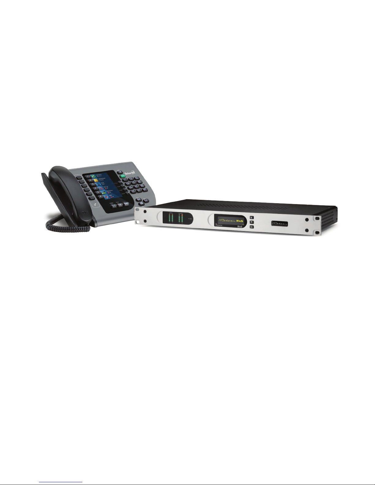
TELOS Hx6
Six-line Broadcast Phone System
USER’S MANUAL
Manual Version 1.0.2, August 2014
part#: 1490-00089-001

Hx6 Manual
© 2014 TLS Corporation. Published by Telos Systems/TLS Corporation. All rights reserved.
Trademarks
Telos Systems, the Telos logo and Hx6 are trademarks of TLS Corporation. All other
trademarks are the property of their respective holders.
Notice
All versions, claims of compatibility, trademarks, etc. of hardware and software products not made by Telos
mentioned in this manual or accompanying material are informational only. Telos Systems makes no endorsement
of any particular product for any purpose, nor claims any responsibility for operation or accuracy. We reserve the
right to make improvements or changes in the products described in this manual which may affect the product
specifications, or to revise the manual without notice.
Warranty
This product is covered by a five year limited warranty, the full text of which is included in this manual.
Updates
The operation of the Hx6 is determined largely by software. We routinely release new versions to add features and
fix bugs. Check the Telos web site for the latest. We encourage you to sign-up for the email notification service
offered on the site.
Feedback
We welcome feedback on any aspect of the Hx6, or this manual. In the past, many good ideas from users have made
their way into software revisions or new products. Please contact us with your comments.
Service
You must contact Telos before returning any equipment for factory service. We will need the serial number, located
on the back of the unit. Telos Systems will issue a Return Authorization number which must be written on the
exterior of your shipping container. Please do not include cables or accessories unless specifically requested by the
technical support engineer at Telos. Be sure to adequately insure your shipment for its replacement value. Packages
without proper authorization may be refused. US customers please contact Telos technical support at +1-216-622-0247.
All other customers should contact your local representative to make arrangements for service.
We support you...
By Phone / Fax:
You may reach our 24/7 Support Team anytime around the clock by calling +1-216-622-0247.
For billing questions or other non-emergency technical questions, call +1-216-241-7225 between 9:30 AM to 6:00
PM USA Eastern Time, Monday through Friday.
Our fax is +1-216-241-4103.
By E-Mail:
Technical support is available at Support@Telos-Systems.com.
All other inquiries at Inquiry@Telos-Systems.com.
Via World Wide Web:
The Telos Web site has a variety of information which may be useful for product selection and support.
The URL is www.Telos-Systems.com
10 9 8 7 6 5 4 3 2 1
Telos Systems USA
This symbol, wherever it appears, alerts you to the presence
of uninsulated, dangerous voltage inside the enclosure –
voltage which may be sufficient to constitute a risk of shock.
This symbol, wherever it appears, alerts you to important
operating and maintenance instructions. Read the manual.
Telos Systems
1241 Superior Avenue E
Cleveland, OH 44114 USA
+1-216-241-7225 (phone)
+1-216-241-4103 (fax)
+1-216-622-0247 (24/7 Technical Support)
Support@Telos-Systems.com
Inquiry@Telos-Systems.com
Notices and Cautions
CAUTION:
THE INSTALLATION AND SERVICE INSTRUCTIONS IN THIS MANUAL ARE FOR USE BY QUALIFIED
PERSONNEL ONLY. TO AVOID ELECTRIC SHOCK, DO NOT PERFORM ANY SERVICING OTHER THAN
THAT CONTAINED IN THE OPERATING INSTRUCTIONS UNLESS YOU ARE QUALIFIED TO DO SO. REFER
ALL SERVICING TO QUALIFIED PERSONNEL.
WARNING:
TO REDUCE THE RISK OF ELECTRICAL SHOCK, DO NOT EXPOSE THIS PRODUCT TO RAIN OR MOISTURE.
USA CLASS A COMPUTING DEVICE INFORMATION TO USER. WARNING:
This equipment generates, uses, and can radiate radio-frequency energy. If it is not installed and used as directed by
this manual, it may cause interference to radio communication. This equipment complies with the limits for a Class
A computing device, as specified by FCC Rules, Part 15, Subpart J, which are designed to provide reasonable protection against such interference when this type of equipment is operated in a commercial environment. Operation
of this equipment in a residential area is likely to cause interference. If it does, the user will be required to eliminate
the interference at the user’s expense. NOTE: Objectionable interference to TV or radio reception can occur if
other devices are connected to this device without the use of shielded interconnect cables. FCC rules require the use
of shielded cables.
CANADA WARNING:
“This digital apparatus does not exceed the Class A limits for radio noise emissions set out in the Radio Interference
Regulations of the Canadian Department of Communications.”“Le present appareil numerique n’emet pas de
bruits radioelectriques depassant les limites applicables aux appareils numeriques (de Class A) prescrites dans le
reglement sur le brouillage radioelectrique edicte par le ministere des Communications du Canada.”

iv |
Table of Contents
We support you... . . . . . . . . . . . . . . . . . . . . . . . . . . . . ii
A Letter from our Vice President . . . . . . . . . . . . . . . . . . . . . . vii
1 Introduction 1
1.1 The Hx6 . . . . . . . . . . . . . . . . . . . . . . . . . . . . . . . 1
1.2 Features. . . . . . . . . . . . . . . . . . . . . . . . . . . . . . . 1
1.3 Integrated Service Digital Networks (ISDN) . . . . . . . . . . . . . . . 2
2 Installation 5
2.1 Getting started . . . . . . . . . . . . . . . . . . . . . . . . . . . 5
2.2 TELCO . . . . . . . . . . . . . . . . . . . . . . . . . . . . . . . . 5
2.2.1 Plain old telephone service – POTS . . . . . . . . . . . . . . . . 6
2.2.2 Integrated Service Digital Networks – ISDN . . . . . . . . . . . . 6
2.2.3 Integration with a PBX . . . . . . . . . . . . . . . . . . . . . 8
2.3 Audio . . . . . . . . . . . . . . . . . . . . . . . . . . . . . . . . 9
2.3.1 Analog Audio . . . . . . . . . . . . . . . . . . . . . . . . . 9
2.3.2 AES/EBU Digital Audio . . . . . . . . . . . . . . . . . . . . . 9
2.3.3 Livewire Audio . . . . . . . . . . . . . . . . . . . . . . . . . 10
2.4 Basic Web Interface Conguration . . . . . . . . . . . . . . . . . . . 11
2.5 Client Conguration . . . . . . . . . . . . . . . . . . . . . . . . .13
2.5.1 Vset6 . . . . . . . . . . . . . . . . . . . . . . . . . . . . . 13
2.5.2 XScreen . . . . . . . . . . . . . . . . . . . . . . . . . . . . 15
2.5.3 Axia iQ surface . . . . . . . . . . . . . . . . . . . . . . . . . 16
2.5.4 Axia Element surface . . . . . . . . . . . . . . . . . . . . . . 16
3 User Operation 17
4 Detailed Conguration & Reference 23
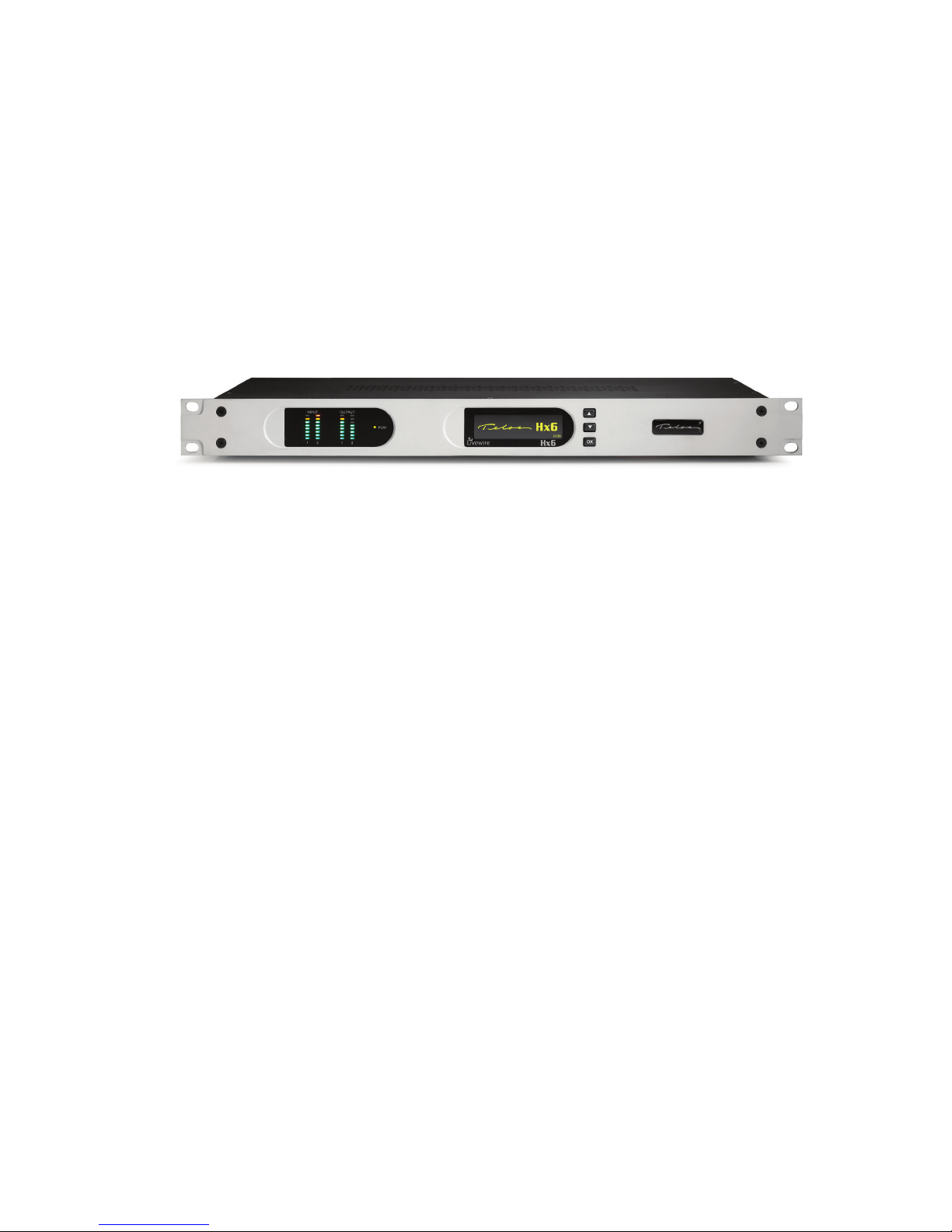
4.1 Front Panel . . . . . . . . . . . . . . . . . . . . . . . . . . . . .23
4.1.1 Audio Menu . . . . . . . . . . . . . . . . . . . . . . . . . . 24
4.1.2 Telco Menu. . . . . . . . . . . . . . . . . . . . . . . . . . . 25
4.1.3 System Menu . . . . . . . . . . . . . . . . . . . . . . . . .26

HX6 MANUAL | v
4.2 Web User Interface . . . . . . . . . . . . . . . . . . . . . . . . . . 26
4.2.1 Status . . . . . . . . . . . . . . . . . . . . . . . . . . . . . 27
4.2.2 Telco . . . . . . . . . . . . . . . . . . . . . . . . . . . . .28
4.2.3 Audio . . . . . . . . . . . . . . . . . . . . . . . . . . . . . 33
4.2.4 Setup Wizard . . . . . . . . . . . . . . . . . . . . . . . . . . 37
4.2.5 Phonebook . . . . . . . . . . . . . . . . . . . . . . . . . .39
4.2.6 Livewire Audio . . . . . . . . . . . . . . . . . . . . . . . . . 39
4.2.7 Livewire GPIO . . . . . . . . . . . . . . . . . . . . . . . . .40
4.2.8 Livewire QoS . . . . . . . . . . . . . . . . . . . . . . . . . . 41
4.2.9 System . . . . . . . . . . . . . . . . . . . . . . . . . . . .42
4.2.10 Backup . . . . . . . . . . . . . . . . . . . . . . . . . . . . 44
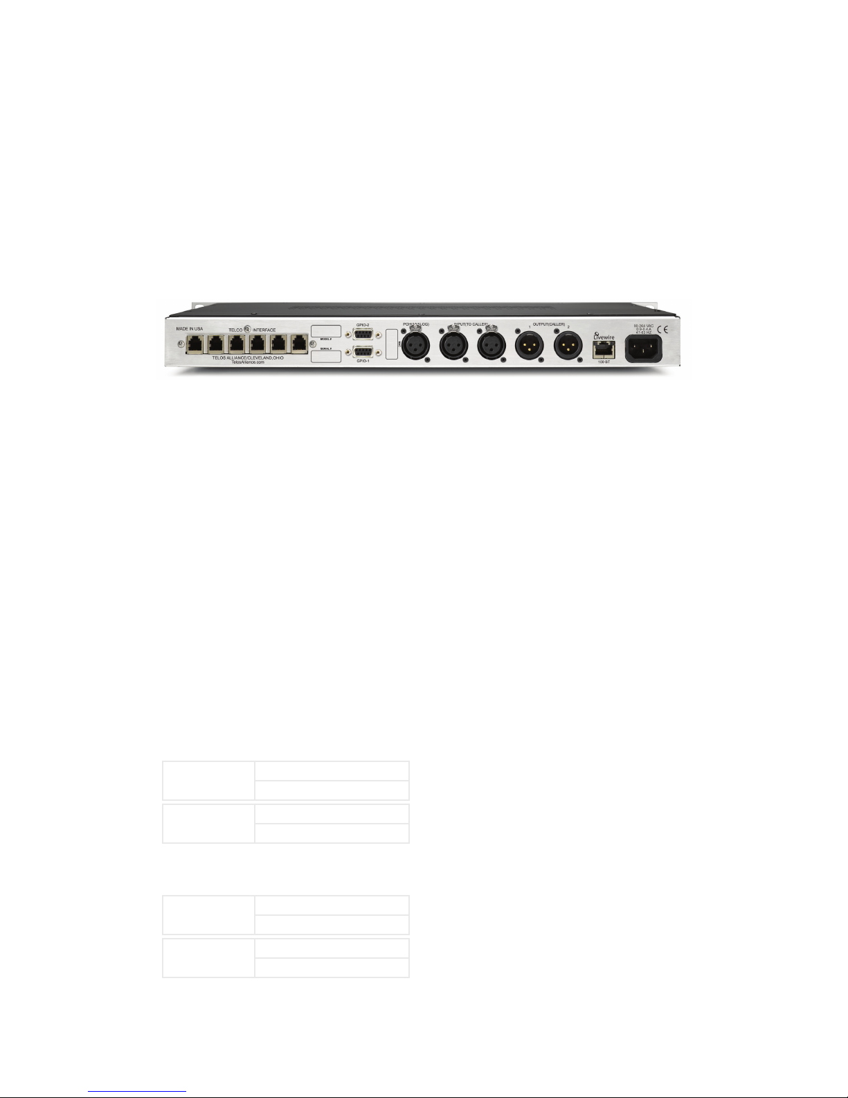
4.3 Back Panel connection . . . . . . . . . . . . . . . . . . . . . . . . 44
4.3.1 Telco interfaces . . . . . . . . . . . . . . . . . . . . . . . . . 44
4.3.2 GPIO interfaces . . . . . . . . . . . . . . . . . . . . . . . . . 45
4.3.3 XLR audio interfaces . . . . . . . . . . . . . . . . . . . . . .46
4.3.4 Network connection . . . . . . . . . . . . . . . . . . . . . .46
4.3.5 AC Power . . . . . . . . . . . . . . . . . . . . . . . . . . .46
5 Technical Data & Troubleshooting 47
5.1 Overview . . . . . . . . . . . . . . . . . . . . . . . . . . . . . . 47
5.2 System Software & Firmware . . . . . . . . . . . . . . . . . . . . . 47
5.3 General Troubleshooting . . . . . . . . . . . . . . . . . . . . . . . 47
5.4 Troubleshooting ISDN Problems . . . . . . . . . . . . . . . . . . . . 49
5.5 Replaceable Modules and Hardware Servicing . . . . . . . . . . . . .52
5.6 ISDN Cause Phrases/Values . . . . . . . . . . . . . . . . . . . . . . 53
5.7 Livewire Audio Troubleshooting . . . . . . . . . . . . . . . . . . . . 60
6 Specications 63
7 Warranty 67


A LETTER FROM OUR VICE PRESIDENT | vii
A Letter from our Vice President
The most compelling audio content and programming
originates with the human voice. Pundits, perpetrators,
experts, celebrities, newsmakers, victims, moderators,
and listeners - they all have opinions. Many want to be
heard. And listeners want to hear them.
It’s for this reason that voice quality over the challenging and changing Public Switched Telephone Network
is an engineering passion for us. Telos’ founder, the late
Steve Church, introduced Digital Signal Processing to
broadcasters for the rst time with the revolutionary
Telos 10 phone hybrid. Since that invention, Steve and
our engineering/development teams have brought
multi-line talkshow systems, ISDN capabilities, and
even large-scale T1- and PRI-based talkshow systems
for multiple studios.
Now that Voice Over IP is becoming commonplace,
broadcasters benet again from a Telos innovation the Telos VX talkshow system. VX connects directly to
VoIP over SIP connections and uses Livewire AoIP to
bring those clear caller voices right into your audio
console or production workow. VX’s IP connectivity is
allowing broadcasters to upgrade to “HD Voice” quality
for on-the-spot reports and priority listener calls.
audio quality. The Telos Z/IP ONE is designed to work
well over the Public Internet, and includes Agile Connection Technology, enabling fast responsiveness to
changing and challenging bandwidth conditions. The
Z/IP ONE is perfect for remote talent, with low-latency
and simplied, two-button connections. Z/IP ONE also
aords super-reliable operation for STL and other program links; and works over any IP link: IP radios, ber,
Internet, or private WAN.
On the pages that follow, you’ll see tools, equipment,
and systems designed to connect your listeners with
compelling audio content. They’ll connect your talent
with listeners, experts, and events with hardly a second
thought to the amazing technology inside.
Thank you for your own dedication, ideas, and comments. Please tell me how you’re creating compelling
content with Telos, and how we can help you do that
even better!
My best,
IP connections are quickly becoming the go-to standard for broadcast remotes, studio-transmitter links,
and audio content distribution. Whether for main or
backup service, permanent or short-term use, Telos
codecs are built for professional use and jaw-dropping
Kirk Harnack
Vice President and Executive Director
Telos Systems


| 1
1
Introduction
1.1 The Hx6
Congratulations on your purchase of Hx6, the latest in multi-line talkshow systems from
Telos. Hx6 combines a six line selector and two third-generation Telos hybrids with Digital
Dynamic EQ. Hx6 also comes with the new AEC – Advanced Echo Cancellation – from
Fraunhofer Labs, revolutionary technology that eliminates open-mic feedback. The two
hybrids are designed to be used within a single studio for airing simultaneous callers and
achieving optimal audio quality.
Hx6 may be controlled by an attached Telos VSet6 phoneset, or by a producer’s PC with
the included Broadcast Bionics Xscreen Lite call screening software. A network interface
connector (RJ45 Jack) is located on the back plane for direct connection to a controller or a
suitable network switch for support of multiple controllers.
The Hx6 may be ordered with either POTS or ISDN (Integrated Service Digital Network)
interface. This provides support for the connection of six lines for the two integrated hybrids.
Audio input and output is accomplished through XLR connectors on the back panel.
♦ Two XLR-Male connectors for audio from Hybrid-1 and Hybrid-2.
♦ Three XLR-Female connectors for audio input to Hybrid-1, to Hybrid-2, and for POH
(Program on Hold).
The Hx6 also supports Livewire audio for connection to a Livewire audio routing system
through the network interface.
The Hx6 has two female D-subminiature 9 pin connectors for GPIO (General Purpose
Input Output).
1.2 Features
Back in the 1980s, Telos pioneered the application of Digital Signal Processing to broadcast
telephone hybrids - a huge step forward from the hot-rodded AT&T speakerphones that
stations had been using. In the decades since, we’ve significantly advanced the art of broadcast
telephony. Your Hx6 system represents the highest state of that art. It includes:
♦ The most advanced digital hybrids yet devised for POTS and ISDN phone lines.New
symmetrical wide-range AGC and noise gate by Omnia, with adjustable gain settings.
♦ Studio adaptation and pitch shifter to prevent feedback in situations where open
speakers are required.

2 | Section 1
♦ An adjustable caller override that improves performance and allows you to individualize
the degree to which the announcer ducks the caller audio.
♦ Telos-exclusive Digital Dynamic EQ (DDEQ) to keep audio spectrally consistent from
call to call.
♦ Separate Send level and Receive level meters for each hybrid.
♦ Worldwide disconnect signal detection (loop drop, dial tone, or reorder tone).
♦ A Livewire Ethernet AoIP interface for one-click connection to Axia studio networks.
♦ Conference linking for high-quality conferencing between callers with no external
equipment needed.
♦ Caller ID support on both ISDN and POTS lines.
♦ Support for up to twelve controllers.
♦ VX control protocol for compatibility with Telos VSet phones and call screening
software which supports the VX protocol.
1.3 Integrated Service Digital Networks (ISDN)
The Hx6 works with either traditional analog Telco lines or with ISDN (Integrated Services
Digital Network). We recommend ISDN service for telephone connections whenever possible.
There is no comparable technology for getting audio to and from the public telephone network.
Even compared to VoIP, ISDN is superior, with its lower delay and higher quality of service.
We provide plenty of advice right here in this manual and live support by people with years of
ISDN experience. (Thousands of Telos ISDN interfaces and Zephyrs are deployed around the
world!) Currently, the dial-up telephone network is nearly entirely digital. Only the “last mile”
copper connections from the telephone Central Office exchange to the customer’s site remain
with the archaic analog scheme. ISDN offers us a way to link the studio directly into the Telco
digital infrastructure without the usual impairments of analog connections.
While the application of digital signal processing to the problem of separating announcer
and caller audio – pioneered by Telos and used in all of our telephone interfaces – has made
a dramatic improvement over analog-only hybrids, using digital phone lines for on-air calls
further improves performance for several reasons:
1. Exceptional send-to-receive isolation. Traditional analog phone lines multiplex both
speech directions in order to use a single pair of wires for a conversation. This causes
what’s referred to as ‘leakage’ – when the announcer’s audio is present on the hybrid
output, creating an annoying ‘hollow’ or ‘tinny’ sound. Telos digital adaptive hybrids
reduce this problem. But ISDN offers independent and separated signal paths, so our
hybrids only have to operate on the far-end analog line, if any. The result is much lower
leakage.
2. Higher send levels. We don’t have to be concerned about regulations designed to prevent
crosstalk on analog lines, so we can increase send-to-caller levels.
3. Lower distortion. The analog-digital conversion chips used in telephone central offices
are poor compared to the converters used in professional audio equipment. Fidelity
is not an important consideration when telephone equipment designers choose parts
for this function. In a professional interface for studio applications, we can afford to
design-in much better converters. Noise-shaping functions permit a larger word-length
converter to provide significantly better distortion and signal-to-noise performance.

INTRODUCTION | 3
4. Lower noise. Because they are digital, ISDN lines are not susceptible to induced noise.
Analog lines are exposed to a variety of noise and impulse trouble-causers as they snake
across town on poles and through your building. Hum is the main problem, given most
lines. Digital lines convey the bits precisely and accurately from the network to your
studio equipment without any perturbation – so the audio remains clean. Even when the
caller is using an analog phone line, the digital connection on the studio side makes for
noticeably lower noise and better overall quality.
5. Higher gain and reduced feedback during multi-line conferencing. When conferencing
is required on analog circuits, hybrids are needed to separate the two audio paths in
order to add gain in each direction. When the gain around the loop exceeds unity, the
unpleasant result is feedback. With digital telephone lines, the hybrid function is more
effective – and more reliably so across a variety of calls. That means more gain can be
inserted between calls before feedback becomes a problem.
6. Digital call setup and supervision. Analog lines use a strange mix of signaling to convey
call status. Loop-current drop signals that a caller has disconnected and blasts of 90 Volts
at 20 Hz mean someone wants you to answer. ISDN uses a modern digital approach to
controlling calls and conveying status information about them. ISDN call set-up times
are often only a few 10s of milliseconds, enhancing production of a fast-paced show.
Perhaps more importantly, when a caller disconnects while waiting on hold, the ISDN
channel communicates this status change instantly. This contrasts with the usual 11-second delay on most analog lines. One of the most common complaints of talk hosts is that
they go to a line where they expect a caller to be waiting, only to be met with a blaring,
annoying dial tone. The chance of this happening with an ISDN line is nearly zero.
ISDN lines come in two varieties: Basic Rate Interface (called BRI, SØ, or ISDN 2 in various
parts of the world) and Primary Rate Interface (PRI, S2 or ISDN 30). BRI lines are the kind we
normally see in broadcast stations, as these are what are used with MPEG codecs such as the
Telos Zephyr and Zephyr Xstream. BRIs have a capability of one or two active 64 kbps channels.
Since the Telos Hx6 is used with BRI lines, we will only consider that type here.
An ISDN line from the central office is a single copper pair identical to a normal (unloaded)
analog line. When it arrives at the subscriber, it is called the U-interface. It is a two-wire connection, usually via an RJ-11 style modular jack.
The S-interface is at the user side of the Network Termination Type 1 (NT1) device. The NT1
is sometimes generically called a NCTE (Network Channel Terminating Equipment) or, in
some countries an NTBA. It is a four-wire connection, via an 8-pin RJ-45 style modular jack.
(Sometimes the S-interface is called S/T. There is a subtle distinction between the two, but it is
not relevant for our purposes here, and the two may be considered to be the same.) In the USA
& Canada NT1 functionality is usually included in the terminal equipment, and indeed the Hx6
in these countries supports the U-interface. In other parts of the world, the telephone company
provides the NT1. Only one NT1 may be connected to a U-interface. However, as many as eight
terminals may be paralleled onto the S bus.
In the USA & Canada a direct connection to the “bare copper” 2-wire U interface is required.
Therefore, the USA & Canada interface module includes an integral NT1 and has RJ-11 style
jacks. In the rest of the world, the telephone company provides the NT1, and the 4-wire ISDN
S-interface will be used with an 8 pin RJ-45 style jack.
In either case each ISDN interface has three connectors. Since each ISDN connection has two
channels, this means each interface module handles 6 ‘dialtones’ or ‘lines’.

4 | Section 1
Data and Voice
ISDN lines may be used for voice signals encoded in standard fashion to allow inter-working
with analog telephones, or may be used to transmit digital data streams. The latter mode is used
for such applications as high-speed Internet access. It is also the mode used with MPEG codecs,
in which case the ISDN line may be carrying voice signals, but is doing so in a format that is
not compatible with the analog part of the telephone network. The distinction is made in the
automatically conveyed Setup message that begins each call.
Normally, the Telos Hx6 uses only the voice mode, so data capability is not necessary. Often
voice costs extra, whereas this is rarely true for data. Of course, you may use a line with both
capabilities. Just be sure the BRI circuit supports the Circuit Switched Voice (CSV) capability
as well as data.
Hunt Groups
The most common configuration for on-air phone system is to have the different phone
numbers linked in a “Hunt Group,” also called “Rollover Lines,” or “Incoming Service Grouping
(ISG).” A hunt group allows you to give out a single number to the audience and each call will
“hunt” to an unused line. Sometimes one or two numbers will be reserved for a “hot line” or
“warm line” in which case those numbers would not be part of the hunt group.
In some cases ISDN lines configured to hunt may deliver all calls to a single DN (phone number).
In this case, you must enter this same DN for each of the DNs on each of the hunting channels.
| 5
2
Installation and Configuration
2.1 Getting Started
The Hx6 mounts in a 1RU high space in a standard 19” rack. There are ventilation holes to the side and top.
Do not restrict the ventilation holes. Find a suitable location that will provide air movement and access to
the front and rear of the Hx6.
Connect the Telco circuits (section 2.2)
Connect the Audio input and output (section 2.3)
Connect power, and once the Telos Hx6 flash screen appears, configure the IP address of the Hx6. Press any
of the three keys to access the configuration options.
Press the down arrow key (▼) to highlight System, press (OK)
Press the (▼) to highlight Networking, press (OK)
Press the (▼) to highlight IP address, press (OK)
Use the (▼) to delete and move the curser back. Once you press (▲), you begin to enter a value at curser
position, starting with 0. Use the (▼) and (▼) to select the desired value, then press (OK). Once the
value is complete, press (OK) once more.
The majority of possible configuration will occur with a PC’s web interface. Use a direct connection between
a PC and the Hx6 with the use of a cross over cable or a normal patch cable to your LAN (local area network). Connect the required cable to the Network port. The PC should have an IP address that is within the
same subnet as the Hx6. (section 2.4)
Configure clients to function with the Hx6. (section 2.5)
2.2 TELCO
The Hx6 has one slot for either a POTS or ISDN Telco interface module, supporting up to six lines. There are
three subsections to the Telco installation. They are:
♦ 2.2.1 Plain old telephone service – POTS
♦ 2.2.2 Integrated Service Digital Networks – ISDN
♦ 2.2.3 Integration with a PBX (private telephone system)

6 | Section 2
2.2.1 Plain old telephone service – POTS (Analog lines)
The Hx6 uses a plug-in interface module to attach to POTS (regular, analog loop start, telephone lines). The
country setting is accessed from the front display. The default country is USA.
From the Status screen, press any of the three keys to access the configuration options.
Press the down arrow key (▼) to highlight Telecom, press (OK)
Press (▼) to highlight POTS, press (OK)
Press (▼) to highlight Country, press (OK)
Use the (▼) and (▲) to select your country, press (OK).
If you do not see your country listed you should use CTR21 or USA. The module has six modular jacks.
The type of jack will be a six position four pin RJ-11 style. The connection is to the center two pins of this
jack. Note: Unlike our older products, the Hx6 does not have the loop through provision for POTS lines.
The POTS lines used with the Hx6 should be dedicated. The yellow and black leads (pins 2 and 5) of the
modular connectors should be disconnected and insulated.
IMPORTANT
When we say POTS lines, we mean just that – plain old analog loop start telephone lines. A rule
of thumb – if a line works with an analog modem or fax machine, it will work with the Hx6.
Analog Ground Start lines can be used for incoming calls only. However you will need to set
Loop Check in the Telco menu to No for these lines to be recognized properly.
Be careful not to connect the Hx6 to PBX ports intended for proprietary telephones. These
sometimes have voltages that could damage the Hx6.
2.2.2 Integrated Service Digital Networks - ISDN
The Hx6 uses a plug-in module to attach to ISDN. The ISDN module has three modular jacks. The type of
jack will be either a six position RJ-11 style or an eight position RJ-45 style depending upon whether it is the
version for USA & Canada or the rest of the world.
The correspondence between the interface slot to the system line number for is from left to right when viewing the Hx6 from the rear. Therefore, the leftmost jack would be lines one and two. All ISDN BRI circuits
must use the same ISDN protocol setting.
ISDN in USA & Canada: Using the U Interface
Connect the ISDN line from the telephone central office directly to the RJ-11 style U-interface modular jack
on the rear panel. Each module has three jacks and each jack has an associated LED.
IMPORTANT
Remember that the U interface connects to a long telephone line and can convey lightning
surges into the Hx6. Surge protectors intended for analog lines work to protect U-interfaces.
We recommend that you install one for each line.

INSTALLATION AND CONFIGURATION | 7
U-interface Status LEDs
The small green LED on the ISDN interface card near each U jack indicate the status of the corresponding ISDN circuit. Rapid flashing (about five times per second) indicates a loss of the ISDN at the lowest
(physical) level. If the Hx6 can contact the central office or an active U repeater, the LED will blink slowly
– about once per second. The LED will come on solid when handshaking is completed and all is OK. If these
LEDs do not light continuously once you have connected your ISDN circuits, you may wish to skip ahead to
Section 5.4 for help with troubleshooting the problem.
Hx6 U-interface (RJ-11)
PIN DESCRIPTION
1 N/C
2 N/C
3 LINE R
4 LINE T
5 N/C
6 N/C
Note that the polarity of the line connections doesn’t matter.
ISDN Worldwide (outside the USA & Canada): The S/T Interface
The S-interface version of the Hx6 connects to the NT1 at one of its terminal jacks. The NT1 is sometimes
generically called a NCTE (Network Channel Terminating Equipment) or, in some countries an NTBA.
Hx6 S-Interface (RJ-45)
PIN DESCRIPTION
1 N/C
2 N/C
3 TRANSMIT TO NETWORK +
4 RECEIVE FROM NETWORK +
5 RECEIVE FROM NETWORK -
6 TRANSMIT TO NETWORK -
7 N/C
8 N/C
ISDN S-interface cable
Use only an 8-conductor RJ-45 style cable. Unshielded twisted pair Category 3 or better cable should be used.
ISDN S-Interface Cable (RJ-45)
PIN COLOR DESCRIPTION
1 WHITE/GREEN PS3 POWER +/GROUND (OPTIONAL)
2 GREEN PS3 POWER – (OPTIONAL)
3 WHITE/ORANGE TRANSMIT TO NETWORK +
4 BLUE RECEIVE FROM NETWORK +
5 WHITE/BLUE RECEIVE FROM NETWORK -
6 ORANGE TRANSMIT TO NETWORK -
7 WHITE/BROWN PS2 POWER - (OPTIONAL) **
8 BROWN PS2 POWER +/GROUND (OPTIONAL) **
TIA 568A Category 5 cable colors shown. Both ends are wired identically - not crossover.
** The Hx6 does not use these power connections

8 | Section 2
When fully wired, this cable has four twisted pairs ‘straight through’ just as with cables used for Ethernet.
Both ends are wired identically. The outside pairs are not required and may be omitted.
2.2.3 Integration with a PBX
The Hx6 will usually be used independently of any other phone system in your facility. But it is possible to
have one or more of the lines come off another phone system. Depending upon the PBX and your preferences, this can be either ISDN BRI or POTS.
Consider having at least one line directly from the Telco to keep your Hx6 up and running even if the PBX or
its Telco connection goes down.
Using ISDN through PBX
Telos equipment has been used satisfactorily using BRI off the following PBX Switches:
USA and Canada
Nortel Meridian Option 11, 2 wire (U interface). Protocol ID = 6. [user report]
Lucent/Avaya Definity, 2 wire (U interface) [user report]
Avaya IP Office (must use Q.931 mu setting on Telos) [user report]
Outside of the USA
Siemens HiCom series, 4 wire (S interface) [user report]
ETS300 Euro-ISDN is available from many PBX systems outside the USA and compatibility is generally good.
Unless your PBX is listed above, its support of US/Canada National ISDN-1 is not certain. We recommend
you arrange a test for compatibility before committing to the purchase of the PBX ISDN module.
Contact Telos support for the latest information, or to report your experiences with other switches.
Using POTS through PBX
Most PBX or VoIP telephone systems can provide analog ports for analog equipment such as modems and
fax machines. You will need such ports to connect a POTS Hx6 to a PBX.
A few years ago, we advised that hybrid performance was best when equipment was connected directly
to the lines from the Telco. Today, this is not always true. If the PBX is connected to the Telco using digital
lines (such as T1, E1, PRI, S2M, etc), performance through a digital PBX will generally be better than direct
connections to copper analog circuits. This is particularly so if you are located a significant distance from
the Telco central office.
The biggest variable when connecting to a PBX analog port is the quality of the analog port. We have found
that many PBX manufacturers offer more than one analog port option. The better port can usually be
distinguished by its higher cost, and the fact that it may offer 48 volts rather than 24 volts. The Hx6 will
work with either voltage; however experience has shown that the 48-volt version usually has better quality
transformers and other components, resulting in better hybrid performance.
The other thing to investigate is whether the PBX offers ‘Loop Current Wink’ or ‘CPC’ (Calling Party
Control) on the analog ports. Without this supervision, the Hx6 will not detect that a caller on hold has
hung up, and your talent will get a recording “please hang up and dial again…” or dial tone when attempting
to air such calls.
INSTALLATION AND CONFIGURATION | 9
2.3 Audio
The Hx6 has three female XLR and two male XLR connectors at the rear. The XLR ports support either
analog or AES/EBU digital (available option). The Hx6 also supports Livewire audio through the network
connection. When Livewire inputs are used, the Analog /AES inputs are switched off. Should the Livewire
inputs fail, Analog/AES inputs are switched on.
2.3.1 Analog Audio
Output 1 is associated with Hybrid 1 audio. Output 2 is Hybrid 2 audio. Connect the output ports to your
mixer or device you intend to use the Hx6 with. The XLR outs are standard active balance outs:
♦ Pin 1 – Ground
♦ Pin 2 – Positive (High)
♦ Pin 3 – Negative (Low)
Input 1 is the audio feeding Hybrid 1 and Input 2 is audio feeding Hybrid 2. The Hx6 inputs must be fed
send-to-caller audio that is free of the caller’s audio, a ‘mix-minus’. A mix-minus is a mix of all audio except
the caller audio. The term mix-minus may also be referred to as ‘M-1’ or ‘clean feed’.
Modern day broadcast consoles should provide an output that fulfill this need. If not, then you will need to
build a mix of sources to be fed to the Hx6 with a utility bus.
2.3.2 AES/EBU digital connections
The Hx6 can be ordered with AES audio i/o. This requires additional hardware to be added at the factory.
When this option is in place, The XLRs described in the Analog section are used for the AES/EBU digital
connections. A single AES/EBU digital stream is two channels of audio. Output 1 has Hybrid 1 audio on
Channel-1 (Left channel) and Hybrid 2 audio on Channel-2 (Right channel). Output 2 has Hybrid 2 audio
on Channel-1 and Hybrid 1 audio on Channel-2.
Output 1 (XLR1)
Output 2 (XLR2)
Inputs have two options, 2-channel or AES POH. In 2-channel mode, left side of the AES input stream will
be used to feed the caller on the Hybrid.
Input 1 (XLR1)
Ch1 (Left) Hybrid 1
Ch2 (Right) Hybrid 2
Ch1 (Left) Hybrid 2
Ch2 (Right) Hybrid 1
Ch1 (Left) Hybrid 1
Input 2 (XLR2)
Ch 1 (Left) Hybrid 2
10 | Section 2
In AES POH mode, left side of AES input 1 is To Hybrid 1 while right side is To Hybrid 2. The second AES
Input is the POH input.
Input 1 (XLR1)
Input 2 (XLR2)
Which mode used is set in the web interface.
Ch1 (Left) To Hybrid 1
Ch2 (Right) To Hybrid 2
POH
2.3.3 Livewire audio connections
The Hx6 supports Livewire audio I/O through the network connection. To use the Livewire I/O, the Hx6
should be connected to an Axia approved network switch that supports QoS (Quality of Service) settings
as well as multicast control protocols. To enabled the Livewire audio, connect to the Hx6 web interface
and select the Livewire Configuration link. Login will be requested; the default Username is user ; leave the
password field blank.
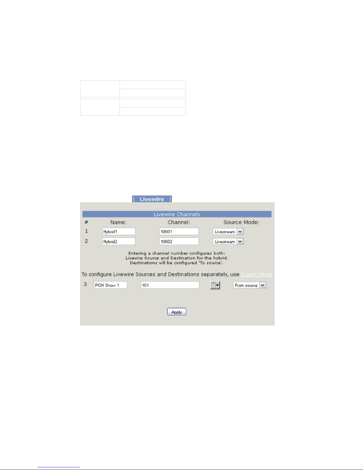
Provide unique Livewire channels for the two hybrids and select the Livestream mode. These will be the
Livewire audio sources for Hybrid 1 and Hybrid 2. The send audio to the callers will be automatically
configured for you. If you want specific control of the send audio, select the Expert Mode. This is covered in
Section 4.2.5.
The POH input is configured below. You can directly type the Livewire channel of the hold audio or select
the browse button to the right of the channel text box and select a source from the network in a pop window.
Don’t forget to press the Apply button when you are done with your Livewire configuration.
INSTALLATION AND CONFIGURATION | 11
2.4 Basic web interface Conguration
Some basic settings need to be entered into the web interface before you can operate your Hx6. You can
connect a PC directly to the Hx6's Ethernet port using a crossover cable, or connect the Hx6 and your PC to
your studio LAN. Once done, open your Web browser and enter the IP address you previously assigned to
your Hx6.
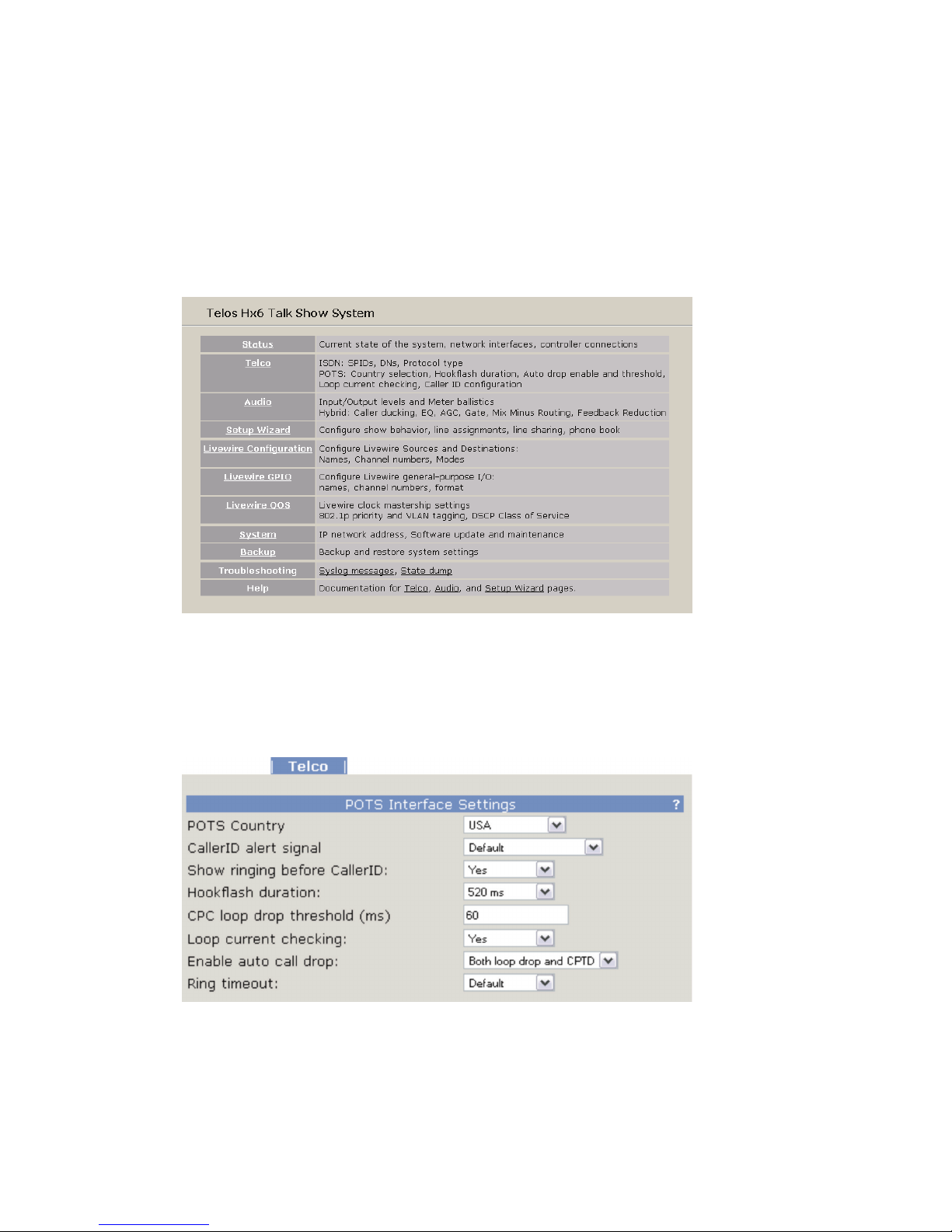
You'll be greeted with the Home screen, shown above. Select the Telco page to configure the needed POTS
interface or ISDN interface settings. When first entering into any of the HTML pages, a login request will appear.
Username is user and the password should be left blank.
POTS Interface
For now, verify that the correct Country setting is selected in the Telco menu. For reference on the other
settings, refer to the detailed configuration section. You can also select the “?” at the corner to open a pop up
help screen which will provide information on the various options available.
12 | Section 2
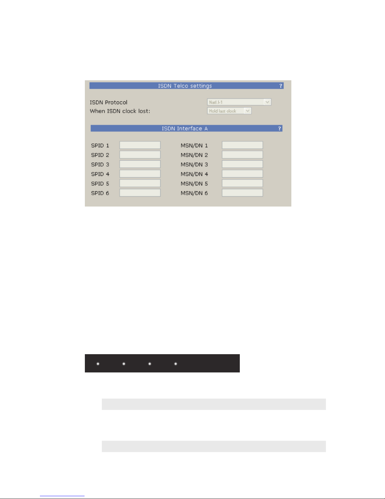
ISDN Interface
If using ISDN, select the required ISDN protocol. For the USA and Canada, this will usually be Natl.I-1. For
Europe and much of the rest of the world, it will be ETS300.
For Natl.I-1, enter the SPIDs for each voice channel given to you by the telephone company. Leave this blank
for other protocols.
Enter the DN (Directory Number) or MSN for each voice channel. The DNs, sometimes called Listed
Directory Numbers or LDNs, are your (usually 7-digit) phone number as listed in the telephone directory.
They normally do not include the area code.
In some cases, you may need to enter 10 digits for your DNs. If you have difficulties with incoming calls, try
this:
Click “Apply”, then “Reboot Now” to activate the ISDN circuits.
Is the ISDN working?
Successful initialization of a line will be indicated by the idle line state on the front display of the Hx6. This
state is shown with a single dot for each active line in the center row of the front display.
The same indicator is also available on the Status page of the web interface.
4 active lines shown initialized
TIPS
Incorrectly entered SPIDs are the most common problem users in the USA & Canada have
placing ISDN calls. Compare the SPIDs you have entered with the SPIDs provided to you on by
the phone company to be certain that you have entered them correctly. Do not add anything
to your SPIDs. Note that there are no hyphens, dashes (-), or spaces in SPIDs so the system will
not allow you to enter any non-numeric characters. If your installer has included them in the
SPID, ignore them.

INSTALLATION AND CONFIGURATION | 13
For a list of known working USA SPIDs by telephone company, see Appendix A.
If you have PTP (AT&T Point-to-Point) or ETS300 (Euro-ISDN) ISDN protocol, you should not
enter anything in the SPID elds.
If you experience problems only with incoming calls, check your DNs.
2.5 Client Conguration
The Hx6 supports the VX control protocol allowing for control clients to connect through a TCP connection
(a network connection). The Hx6 supports up to 12 simultaneous clients which may be a combination of
any items listed below.
Available clients are:
♦ VSet6 (2.4.1)
♦ XScreen Lite (2.4.2)
♦ Axia iQ surface (2.4.3)
♦ Axia Element surface (2.4.4)
2.5.1 Vset6 phone
Connect the VSet6 to your network or directly to the Hx6. Note that the VSet6 is powered by Power-overEthernet (PoE). This requires that you have a PoE enabled switch or that you use the PoE injector which is
included with the VSet6. The injector will have two RJ45 ports, one is for data and the other is data+power.
Make sure you plug the data+power port to the VSet6.
After the VSet has booted, you should see the “Not connected.” notification on the screen.
Press the MENU button.
Press the 6 key (“Next…”)
Press and hold the 2 key (“Setup) for 5 seconds
14 | Section 2
Press the 3 key (“VSet IP Address”) to edit the IP address.
Use the keypad to enter the desired IP address for the VSet. Using the # as a backspace
and the * as a “dot” (.).
You can use the softkeys to cancel the edit by moving UP or DOWN, complete the edit by pressing the
ENTER soft key, or delete a character by pressing the X.
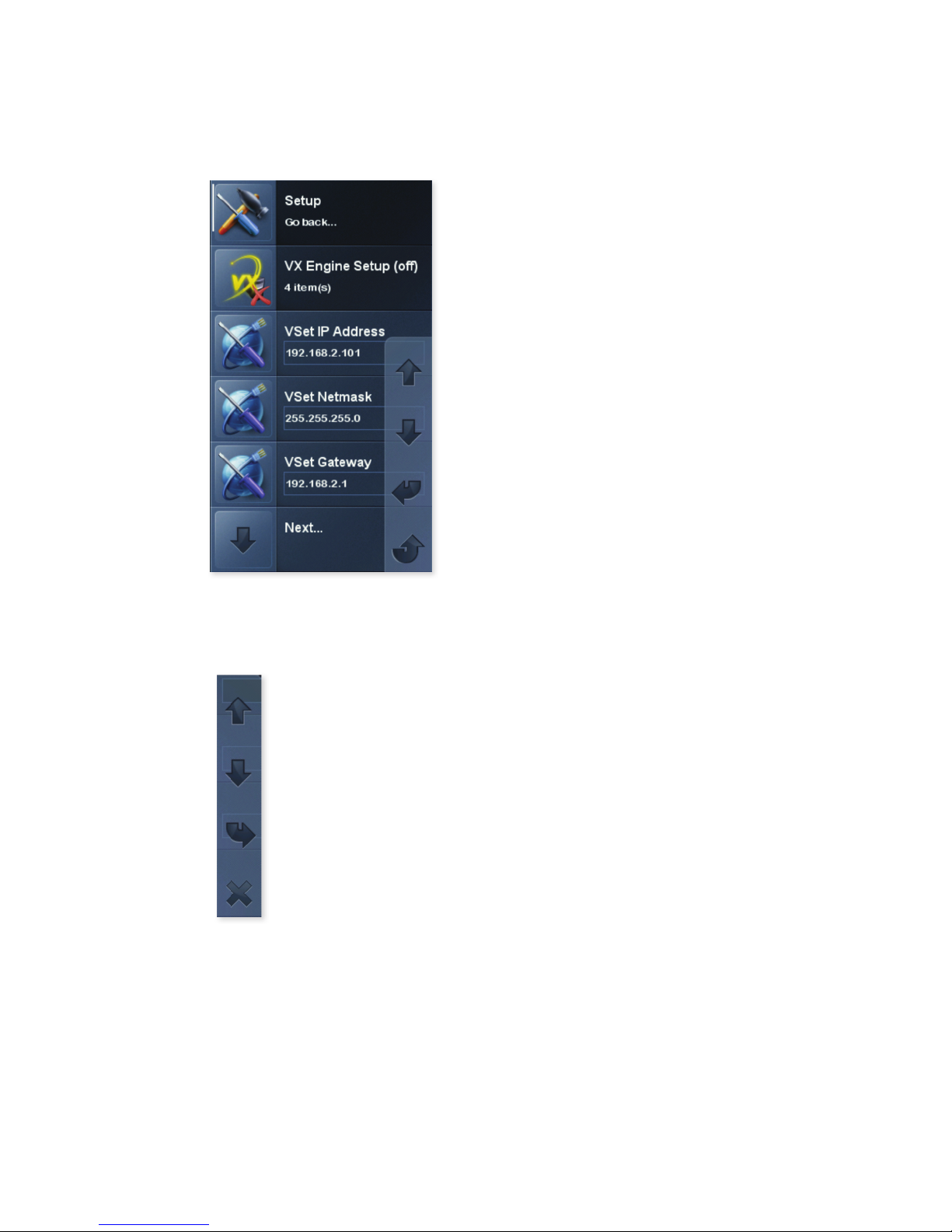
With an IP value assigned to the VSet6, press the 1 key to exit setup and follow by configuring connection to
the Hx6. Press and hold for 5 second the 3 key (“Engine Setup”).
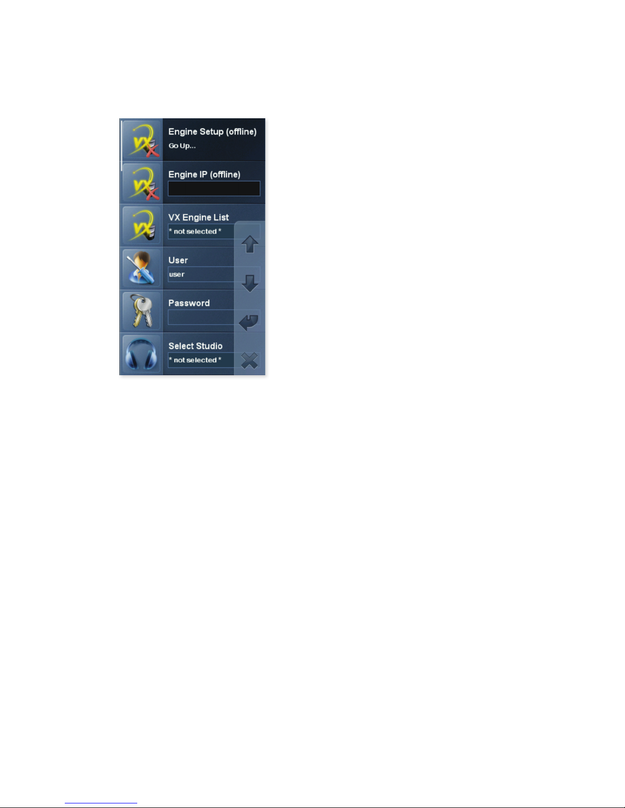
INSTALLATION AND CONFIGURATION | 15
Using the keypad, enter in the IP address of the Hx6. When complete make sure to press the ENTER softkey.
Press the 6 key (“Select Studio”) followed by the 2 key (“Hybrid 1&2”). Once the above steps are complete, the line status should appear on the screen.
The last step is to press the menu key to check on the mode the VSet is running in. Verify the mode is in
“Talent” mode. If the mode shows “Producer”, press the 3 key to toggle it to “Talent”.
The VSet6 has a few setup items you need to go through to connect to the Hx6 because not only is it used
with the Hx6 but can also be used with other Telos products such as the VX.
2.5.2 XScreen Lite
Before installing XScreen Lite, you must think about which machine will be your Master and which will be
Buddys. You need a single Master machine. All other machines must be installed as Buddys and these will
connect to the relevant Master in order to share information for the Hx6. The Master machine runs the
database that stores past call information and the Buddys get access to that information from the Master.
For this reason, the Master machine needs to always be running in order to allow the Buddys to connect to it.
Running the main Control Room / Studio machine as the Master is the usual arrangement.
Once XScreen, version 2.3.00.108 or higher, is installed on the Master machine, a license will need to be
generated. It is strongly recommended that the machine is connected to the internet in order to make this
process as straightforward as possible.
You will need to select Hx6 from the available Telos devices and enter in the IP address of the Hx6. With the
correct parameters entered and a license, XScreen will run.
Refer to: http://wiki.bionics.co.uk/XScreen.MainPage.ashx for the online manual of the XScreen application.
 Loading...