

Telos Hx1, Hx2 User Manual
TELOS Hx1/Hx2
Digital Hybrid Telephone Interface
USER’S MANUAL
Manual Version 1.4b for software version 1.4 or later
11 October, 2010

Telos Hx1 and Hx2 Manual
© 2010 TLS Corporation. Published by Telos Systems/TLS Corporation. All rights reserved.
Trademarks
Telos Systems, the Telos logo and Hx1 and Hx2 are trademarks of TLS Corporation. All other
trademarks are the property of their respective holders.
Notice
All versions, claims of compatibility, trademarks, etc. of hardware and software products not made
by Telos mentioned in this manual or accompanying material are informational only. Telos Systems
makes no endorsement of any particular product for any purpose, nor claims any responsibility for operation or accuracy. We reserve the right to make improvements or changes in the products described
in this manual which may aect the product specications, or to revise the manual without notice.
Warranty
is product is covered by a one year limited warranty, the full text of which is included in this manual.
Updates
e operation of the Hx1 and Hx2 is determined largely by software. We routinely release new
versions to add features and x bugs. Check the Telos web site for the latest. We encourage you to
sign-up for the email notication service oered on the site.
Feedback
We welcome feedback on any aspect of the Telos Hx1 or Hx2, or this manual. In the past, many good
ideas from users have made their way into software revisions or new products. Please contact us with
your comments.
Service
You must contact Telos before returning any equipment for factory service. We will need the serial
number, located on the back of the unit. Telos Systems will issue a Return Authorization number
which must be written on the exterior of your shipping container. Please do not include cables or accessories unless specically requested by the technical support engineer at Telos. Be sure to adequately
insure your shipment for its replacement value. Packages without proper authorization may be refused.
US customers please contact Telos technical support at +1-216-622-0247. All other customers should
contact your local representative to make arrangements for service.
We support you...
By Phone / Fax:
You may reach our 24/7 Support Team anytime around the clock by calling +1-216-622-0247.
For billing questions or other non-emergency technical questions, call +1-216-241-7225 between 9:30
AM to 6:00 PM USA Eastern Time, Monday through Friday.
Our fax is +1-216-241-4103.
By E-Mail:
Technical support is available at Support@Telos-Systems.com.
All other inquiries at Inquiry@Telos-Systems.com.
Via World Wide Web:
e Telos Web site has a variety of information which may be useful for product selection and support.
e URL is www.Telos-Systems.com
10 9 8 7 6 5 4 3 2 1
Telos Systems USA
This symbol, wherever it appears, alerts you to the presence
of uninsulated, dangerous voltage inside the enclosure –
voltage which may be sufficient to constitute a risk of shock.
This symbol, wherever it appears, alerts you to important
operating and maintenance instructions. Read the manual.
Telos Systems
1241 Superior Avenue E
Cleveland, OH 44114 USA
+1-216-241-7225 (phone)
+1-216-241-4103 (fax)
+1-216-622-0247 (24/7 Technical Support)
Support@Telos-Systems.com
Inquiry@Telos-Systems.com
Notices and Cautions
CAUTION:
THE INSTALLATION AND SERVICE INSTRUCTIONS IN THIS MANUAL ARE FOR
USE BY QUALIFIED PERSONNEL ONLY. TO AVOID ELECTRIC SHOCK, DO NOT
PERFORM ANY SERVICING OTHER THAN THAT CONTAINED IN THE OPERATING
INSTRUCTIONS UNLESS YOU ARE QUALIFIED TO DO SO. REFER ALL SERVICING
TO QUALIFIED PERSONNEL.
WARNING:
TO REDUCE THE RISK OF ELECTRICAL SHOCK, DO NOT EXPOSE THIS PRODUCT
TO RAIN OR MOISTURE.
USA CLASS A COMPUTING DEVICE INFORMATION TO USER. WARNING:
is equipment generates, uses, and can radiate radio-frequency energy. If it is not installed and used
as directed by this manual, it may cause interference to radio communication. is equipment complies
with the limits for a Class A computing device, as specied by FCC Rules, Part 15, Subpart J, which
are designed to provide reasonable protection against such interference when this type of equipment
is operated in a commercial environment. Operation of this equipment in a residential area is likely
to cause interference. If it does, the user will be required to eliminate the interference at the user’s
expense. NOTE: Objectionable interference to TV or radio reception can occur if other devices are
connected to this device without the use of shielded interconnect cables. FCC rules require the use of
shielded cables.
CANADA WARNING:
“is digital apparatus does not exceed the Class A limits for radio noise emissions set out in the
Radio Interference Regulations of the Canadian Department of Communications.”“Le present
appareil numerique n’emet pas de bruits radioelectriques depassant les limites applicables aux appareils
numeriques (de Class A) prescrites dans le reglement sur le brouillage radioelectrique edicte par le
ministere des Communications du Canada.”

iv |
Table of Contents
We support you... . . . . . . . . . . . . . . . . . . . . . . . . . . . . .i
A Letter from our President . . . . . . . . . . . . . . . . . . . . . . . . vii
1 Introduction 1
The Hx1 Hybrid . . . . . . . . . . . . . . . . . . . . . . . . . . . . . 1
Purpose . . . . . . . . . . . . . . . . . . . . . . . . . . . . . . . . 1
Features . . . . . . . . . . . . . . . . . . . . . . . . . . . . . . . . 2
The Hx2 Hybrid . . . . . . . . . . . . . . . . . . . . . . . . . . . . . 3
2 Installation 5
Connecting your telco lines . . . . . . . . . . . . . . . . . . . . . . . . 5
Studio Audio Connections . . . . . . . . . . . . . . . . . . . . . . . . 6
Hx2 Internal Mix Minus . . . . . . . . . . . . . . . . . . . . . . . . . 9
Input Audio Connection . . . . . . . . . . . . . . . . . . . . . . . . . 10
Output Audio Connection . . . . . . . . . . . . . . . . . . . . . . . . 11
Remote Control . . . . . . . . . . . . . . . . . . . . . . . . . . . . . 12
Connecting your Hx to other systems and non-standard lines . . . . . . . . 13
Quick Basic Test . . . . . . . . . . . . . . . . . . . . . . . . . . . . . 14
Power Input and Grounding Safety . . . . . . . . . . . . . . . . . . . . 15
3 Operation 17
Front Panel Buttons . . . . . . . . . . . . . . . . . . . . . . . . . . . 17
Line Status Display . . . . . . . . . . . . . . . . . . . . . . . . . . . 17
Metering . . . . . . . . . . . . . . . . . . . . . . . . . . . . . . . . 18
Basic Operation . . . . . . . . . . . . . . . . . . . . . . . . . . . . . 19
4 Conguration Settings 21
Rear Panel DIP Switch Control. . . . . . . . . . . . . . . . . . . . . . . 24
Country Specic Settings . . . . . . . . . . . . . . . . . . . . . . . . . 27
Factory Default Conguration Settings. . . . . . . . . . . . . . . . . . . 32

TELOS HX1/HX2 MANUAL | V
5 AES I/O Option 33
Installation Instructions . . . . . . . . . . . . . . . . . . . . . . . . . 33
AES Channel Assignments . . . . . . . . . . . . . . . . . . . . . . . . 35
Restoring an AES equipped unit to Analog Operation . . . . . . . . . . . . 35
6 Troubleshooting 37
On-Board Diagnostics . . . . . . . . . . . . . . . . . . . . . . . . . . 37
Software Version . . . . . . . . . . . . . . . . . . . . . . . . . . . . 37
DIP Switch Status . . . . . . . . . . . . . . . . . . . . . . . . . . . . 37
T1 Test – 400 hz tone generation . . . . . . . . . . . . . . . . . . . . . 38
T2 Test – Studio Loopback . . . . . . . . . . . . . . . . . . . . . . . . 38
T3 Test – Feed Through Test . . . . . . . . . . . . . . . . . . . . . . . . 39
Hardware Repairs . . . . . . . . . . . . . . . . . . . . . . . . . . . . 39
7 Specications 41
8 Warranty and Application Caution 43
A1 Telephone Terminology Guide A1
A2 Quick Reference Guide: Rear Panel Switches A19
A3 Quick Reference Guide: Internal Switches & Remote Connector pin usage A21

VI | A LETTER FROM OUR PRESIDENT

A LETTER FROM OUR PRESIDENT | VII
A Letter from our President
“What if?” A singularly great question, because it
opens the door to so many other questions and
ideas. Those who ask it are sometimes called dreamers,
as if that were somehow bad, but history has often
proven dreamers to be the avatars of new and exciting things.
“What if?” was the query asked by Steve Church that
led to the start of Telos Systems. In 1984, Steve –
then a young broadcast engineer and part-time talk
show host – wondered whether emerging Digital
Signal Processing (DSP) technology might be useful
to clean up the terrible caller audio then the norm
at radio stations. The result of asking it was the Telos
10, the world’s rst digital telephone hybrid, a
product that changed the face of radio forever.
Looking back at Telos history, “What if?” is found
at the root of many more technologies broadcasters
have since made ubiquitous. “MP3 bit rates are
perfectly matched to the bandwidth of ISDN; what if
we combined them?” “What if we built a box that let
radio stations stream audio on the Internet?” “What
if we could use Ethernet to treat audio as data and
move it around the radio station in real time?” (By
the way, if you recognized the answers to those
questions as the Zephyr ISDN codec, AudioActive
MPEG encoder and Livewire IP-Audio protocol, give
yourself a cookie.)
A new digital tech called AEC (Advanced Echo Cancellation) is helping to literally eliminate the age-old
problem of feedback in open-speaker environments.
And the prize of using the public Internet for remote
connections as reliable as those of switched circuits
is within broadcasters’ grasp, thanks to ever more
sophisticated coding algorithms.
Pioneering ideas aren’t limited just to technology,
though. We believe that investing in people pays o
big, so we’ve assembled the largest R&D team in the
industry, a talented sta of engineers, scientists and
broadcast professionals. We’re also the rst and only
broadcast equipment maker with a 24/7 support
team ready to oer assistance any time of the day
or night. As they say, radio never sleeps – so neither
do we.
As Telos navigates its third decade in broadcasting’s
choppy waters, the spirit of innovation and ideas
that propelled Steve in the early days is still very
much alive. We’re still in love with radio, still turned
on by new technology, still driven to ask “What if?”
If you’re reading this, you are too — for which we
thank you, from the bottom of our hearts.
Got to go; my phone is ringing. It’s Steve Church,
and I bet he wants to ask me a question…
Today, as technology roars ahead, we’re constantly
seeking new ways to apply it to the problems of everyday broadcasting. Voice over IP (VoIP) is particularly
compelling for its ability to packetize high-quality phone
calls and direct them anywhere in the broadcast plant
using ubiquitous, standard Ethernet as a backbone.
Michael “Catsh” Dosch
President

| 1
1
Introduction
Hx1 Hybrid
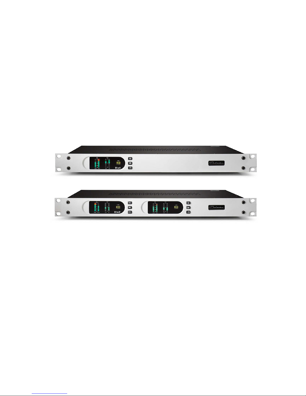
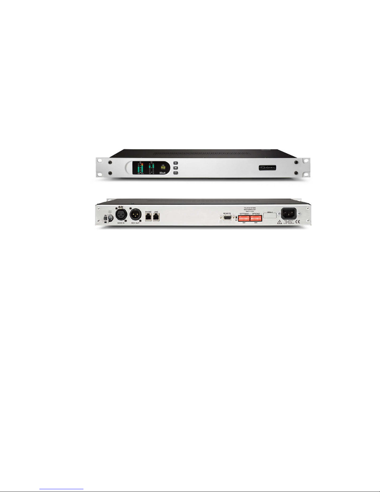
e Telos Hx1 is a single digital hybrid in a 1RU 19 inch rack mount enclosure. It
embodies a state of the art approach to interfacing an analog POTS (Plain Old
Telephone Service) line for broadcast on-air use. e fast, precise digital automaticnulling hybrid allows smooth, natural, conversation without speakerphone-like
up-cutting eects, or the audio distortion and feedback problems often experienced
with lesser hybrid interface devices.
e Hx1 implements a number of features in the digital domain in order to enhance
“real-world” performance. In particular, the hybrid includes a sophisticated automatic
gain control in both the send and receive paths, a carefully implemented override
ducking system, a pitch shifter for feedback reduction, and a digital dynamic EQ that
keeps audio spectrally consistent from call to call.
Purpose
e Telos Hx1 or Hx2 broadcast telephone hybrids are designed to deliver pure caller
audio with as little leakage from the (announcer’s) send audio as possible. Telos uses
state of the art digital techniques to perform the hybrid function – the subtraction
of the send audio from the received caller audio. e fully digital approach assures
consistently good trans-hybrid loss, audio levels and sound quality with varying
telephone line conditions.

2 | Section 1
Features
e Telos Hx1 and Hx2 hybrids include many features that have historically been
“add ons” or options. See the list below.
♦ A high-pass lter reduces hum and low frequency noise. High- frequency
noise above the telephone frequency range is also attenuated.
♦ A smart digital Automatic Gain Control (AGC) smooths output levels. e
gain changes occur naturally, delivering consistent levels without processing
artifacts. A settable noise gate/expander on the receive path reduces phone line
noise during caller pauses.
♦ An adjustable override function allows ducking of the caller while the an-
nouncer is speaking.
♦ Feedback is reduced by a special “pitch shifting” arrangement while echo is
reduced with a basic Acoustic Echo Canceler.
♦ Fixed or adaptive EQ helps to correct deciencies in a callers telephone set or
the network, resulting in a clearer, warmer, more intelligible sound from the
caller.
♦ Front panel metering is provided for input and output levels. EQ gain changes
are displayed in real time.
♦ Auto-Answer capabilities with a selectable ring count allows for unattended
operation.
♦ Worldwide disconnect signal detection allows use of the hybrid in dierent
countries and with various PBXs.
♦ e Hx is equipped with a complete diagnostic system for system set-up and
check-out.
♦ Optional AES3 support is available.
♦ Built-in universal power supply and rack mount design aids in a professional
installation.
♦ e Hx has built-in full remote control capability, including outputs for “line
ringing” and “hybrid in use” indicators.
♦ Telos “Status Symbols” provide clear visual cues to operators.
INTRODUCTION | 3
Hx2 Hybrid
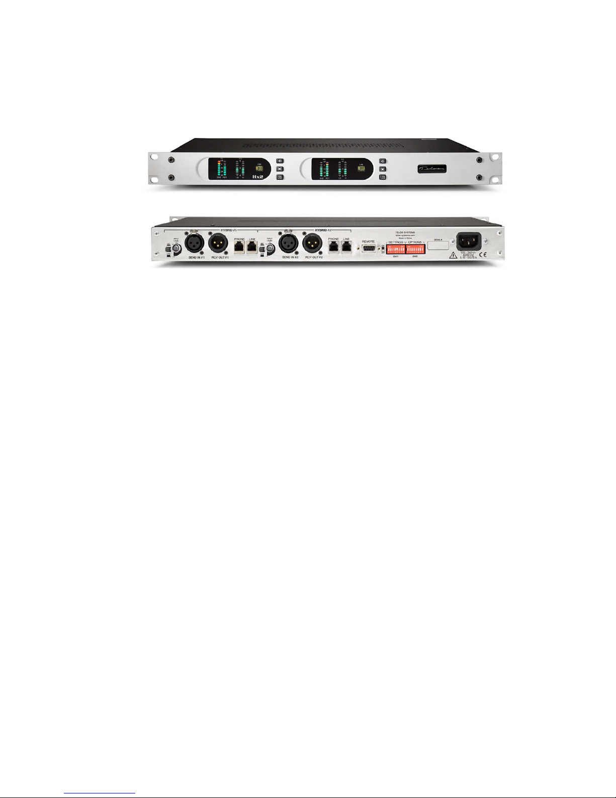
e Telos Hx2 unit consists of two identical digital hybrids in a single 1RU 19 inch
rack-mount enclosure.
e Hx2 can operate as two fully independent hybrids or be congured with an
internal mix-minus to couple the two hybrids, sharing a single mix minus from the
audio console and allowing callers on both hybrids to hear each other and your talent.
e Hx may be controlled remotely via connections available on the unit’s remote
connector (DB-9). Control functions include remote on and o control, and available
status outputs include “line ringing” and “hybrid in use” open-collector indications.
e remote connector allows easy direct connection to 1A2 interfaces, consoles or
other remote control devices.
e unit can be equipped with an optional AES3 module, which plugs into the
motherboard and converts the XLR connections from analog to AES3.


| 5
2
Installation
e Hx1 and 2 mount in a 1RU space in a standard 19” rack. e unit generates very little heat
and needs no special attention for cooling or rack placement. e unit will operate in any environment where the stirred air temperature around the unit is between 0 to 40 degrees Celsius
(32 to 104 degrees Fahrenheit) with a relative humidity of 0 to 98% (non-condensing).
Next installation steps are:
♦ Connect your telco circuits and connect a “looped through” telephone set, if desired.
♦ Connect Audio with analog connections (or AES3 if equipped).
♦ Connect any needed parallel GPIO for remote control operation or to use any of the
available status indications present on the rear panel DB-9 connector.
♦ Power up the Hx and do a quick basic operational test using the factory settings.
is installation section covers all of the above. After completing these steps you’ll be ready to
move on to conguration for your specic situation.
2.1 Connecting your telco lines
e Hx1 & 2 use standard RJ-11 type “modular” telephone connectors. Only the two center
pins that carry the analog line’s “tip and ring” are used. Connect the telephone line using the rear
panel “LINE” jack.
e Hx is designed to work with ordinary “loop start” analog phone lines, though it can operate on PBX extensions and VoIP Analog Terminal Adapters (ATA’s). Hybrid performance and
system behavior on these kinds of lines may vary. If you plan to use your Hx on any of these
types of lines or connect your unit to other legacy Telos systems such as the 1A2 interface or the
Direct Interface Module and others, please see section 2.7.
Lines that carry “Shared Line DSL” can be problematic. It’s suggested that you avoid using the
Hx on lines that carry DSL, but if you must use one, be sure to use a “line splitter” or DSL lter
in series with the “LINE” jack on the Hx. DSL lines have data carriers above the voice band of
the circuit, usually from 25 khz to 1004 khz. DSL lters strip away the high frequency data carriers and pass on the 0-4 khz voice band and signaling. Some lters are better than others and
sometimes better results can be obtained by cascading several lters, each rolling o more of the
high frequency energy. On a line with DSL you might hear more “hiss” and “hash” than with a
normal line.
An analog phone set may be plugged into the “PHONE” jack. e telephone can be used when
the Hx is “o”. You might want to disable the telephone’s ringer if you are in a studio environment. e Hx has a “line ringing” open collector output that you can use to light lamps or
strobes. See Section 2.6: the “remote” connector.
e Hx has an “auto-answer” function that you can enable. See section 4.1.

6 | Section 2
2.2 Studio Audio Connections
Mix-Minus
e Hx must be fed send-to-caller audio that is free of the caller audio, a ‘mix-minus’. A mixminus is a mix of all of your audio sources that will be placed on-air (or recorded) except the
caller audio – thus the mix-minus designation. e European term M-1 (mix minus one) is perhaps a clearer term. A mix-minus is also sometimes referred to as a ‘clean feed’. e important
thing to remember is that the hybrid must not ‘chase its tail’ – the condition when its output
makes its way somehow back to the input.
Hot Tip
Many hybrid installation problems are caused by an inadvertent signal path which creates a
loop from the hybrid’s output back to its own input. Some consoles allow this when certain
control combinations are selected by the user. In some cases, it may be as simple a mistake
as assigning the hybrid to whichever bus is feeding the hybrid. This is the rst place to look
when strange or erratic performance is experienced. The quickest test is to bring up only the
hybrid in question on the board and select a line. Dial tone should not appear on the send
meter of the hybrid in question.
Using a modern broadcast console’s mix-minus capability
Most modern broadcast consoles have provision for multiple mix-minus busses. e best
consoles allow selective feeds to the phone system. is is useful since sometimes you want only
one microphone feeding the phone, but sometimes you want to three or four mics (during the
morning show, for instance), and sometimes you want to play some audio piece that callers need
to hear and react to such as contest sound eects, etc. Some even provide for separate ‘on-air’
and ‘o line’ (recording) telephone modes.
‘Making do’ with an older console
Consoles made before around 1990 rarely had good support for mix-minuses, and almost never
for more than one or two. With one of these oldsters, some clever improvisation is going to
be needed. Here we describe a possible scenario that can be used as a starting point for your
situation. We assume an older console with Program and Audition as the main busses. ere
is another bus of some kind that can be adapted for mix-minus application. We’ll call this the
‘Utility’ bus. All sources, including the hybrid, will be assigned to Program, so the audience can
hear them, as usual. We will also assign most of these sources to Utility as well, just never the
fader with the hybrid’s own audio.

INSTALLATION | 7
Line
Hybrid
Utility Bus
PGM Bus
To Telco
{
PGM Out
To Rec Ch.1
To Rec Ch.2
Inputs
is arrangement is exible, allowing the operator to place any or all sources in Utility for the
caller to hear. In our example we have the fortunate case that the console permits the Utility bus
to be fed pre-fader, letting the announcer easily use the telephone system for o-air conversations.
A recorder can be attached to the Utility and hybrid outputs to record announcer + phone
audio. is is often done as shown here, with each signal to a separate track. A drawback is the
potential for the operator to accidentally put the hybrid in Utility, in which case it is no longer a
mix-minus. To avoid this error, the signal path could be permanently disconnected by removing
the summing resistors, or some such creative operation.
If no bus is available to feed the Hx, you could use an external mixer that bridges the microphone inputs to achieve the same eect.
e Hx2 has multiple hybrids and works best if two faders can be assigned to the telephone
system with two associated mix-minuses, one for each telephone line. is is probably not going
to be easy with an older console. But the Hx2 has an option to work with a single external mixminus by making an internal cross-connection of the hybrids. See Section 2.3 for more on this.
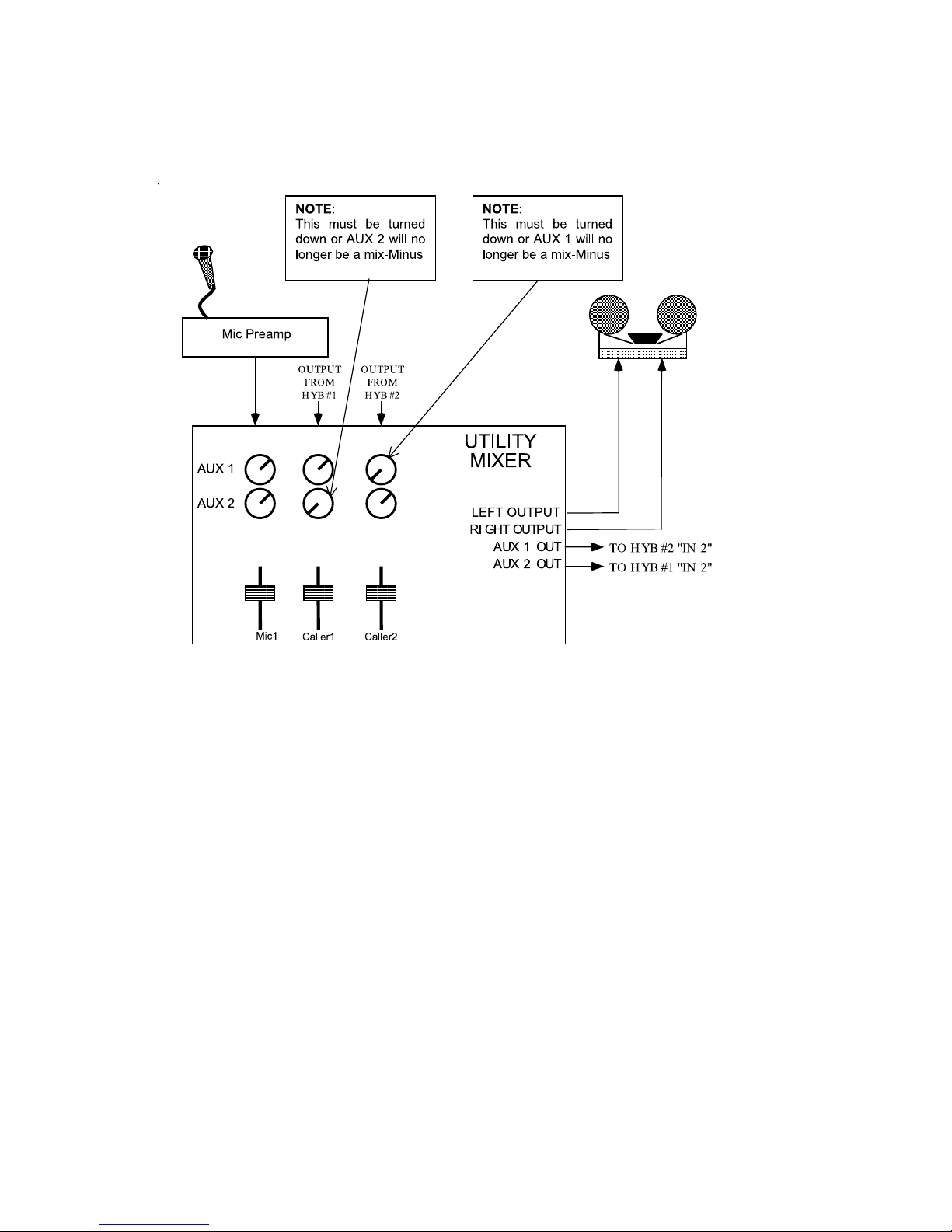
Using a small mixer
A small audio mixer is used to record interviews o the telephone line using a single hybrid.
e mixer’s main bus is fed to the recording device. Both the microphone and the hybrid will be
brought up on the faders so the interview can be recorded.
Most small mixers (such as those made by Mackie) have one or two Aux send busses, so we will
use these to feed the telephone system. We will turn up Aux for the microphone but we will
make sure it is turned fully o for the each channel that has the corresponding caller audio.
8 | Section 2
Using a production-style console
e Production-style consoles often used for TV audio will have multiple Aux send busses that
can be used in a similar way to the small mixer example above. Each hybrid is sent from an Aux
bus and everything the caller needs to hear is mixed into that bus, taking care to keep the hybrid
itself o the bus.
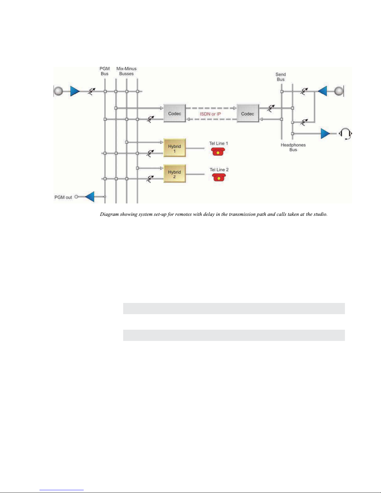
Phones and Remotes
When on remote, to save money and hassle, calls are usually received at the studio, rather than
at the remote site. In this situation, caller audio must be fed to the remote talent so that they
can hear and respond to callers. Moreover, the callers need to hear the talent. In many cases, the
remotes are suciently distant that talent cannot monitor the station for the caller feed. Even
if they could, the profanity delay would be a problem, since the talent needs to hear the callers
pre-delay.
All perceptual codecs (such as the Telos Zephyr or X-Stream) or any IP codec, have too much
delay for talent at remote locations to hear themselves via a round-trip loop. erefore, another
mix-minus is required to feed a codec.
e talent hears callers via the codec return path. As before, you feed this return with mixminus: a mix of everything on the program bus minus the remote audio. As for the second half
of the equation, the callers hear the talent because the remote feed is added to the telephone
mix-minus bus. is is no problem if you have a set-up that permits selective assignment to the
hybrid mix-minus.
INSTALLATION | 9
A problem with this arrangement is a result of a hybrid with too much leakage combined
with the system delay. If the hybrid isn’t doing a good job of preventing the send audio from
leaking to its output, the special remote send mix-minus is corrupted. Remember, if any of the
announcer audio from the remote site is returned via the monitor feed, it will be delayed by the
digital link, causing an echo eect. e Telos Hx really shows its stu in this situation. Because
it has such good trans-hybrid loss, leakage is not at all likely to be a problem. And should there
ever be a problem, you can solve it by increasing the amount of ducking. See Section 4.2.
Note
The Telos Hx has the more common pin-outs used for three pin XLR inputs & outputs. You
can easily remember the correct signals when wiring connectors using the phrase “George
Washington Bridge.” Pin 1 = G = Ground, Pin 2 = W = “+” = White (typical color in mic cable, if
there is no white there will be a red conductor), and Pin 3 = B = “-” = Black.
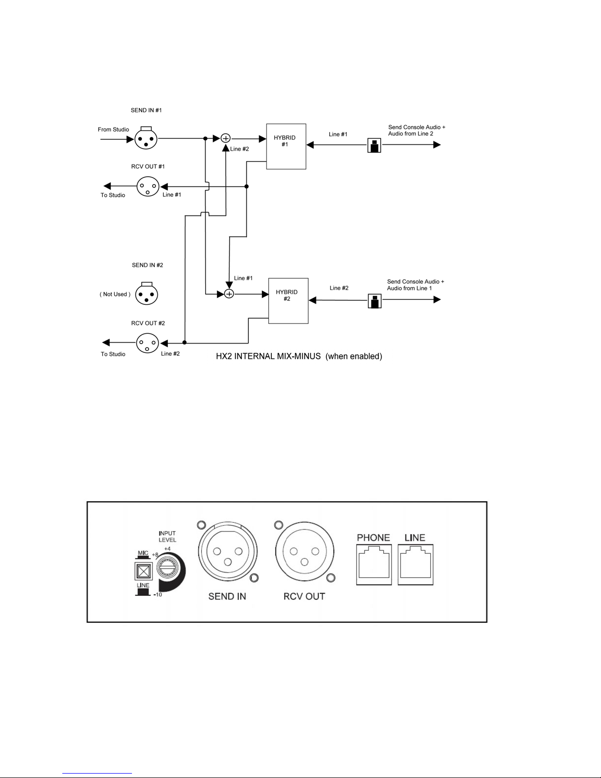
2.3 Hx2 Internal Mix Minus
e two hybrids in the Hx2 unit may be congured so that a single mix-minus feed may be used
for both hybrids, with each hybrid’s output fed into the other’s input internally at unity gain (so
that the callers can hear each other) and sums each with the audio from the consoles mix-minus
output. Only the SEND IN #1 input is used to feed both hybrids.
Both hybrid outputs still function independently. e two hybrid outputs are NOT summed
together, so you should provide a fader for each hybrid. e consoles mix-minus must be
congured so that no hybrid’s output gets sent to its own input.
10 | Section 2
e gure above illustrates which signals are combined together inside the Digital Signal
Processor and routed to each connector when the Hx2 internal mix-minus feature is enabled.
Use this option if you only have a single mix-minus available from your console and you wish to
use both hybrids to conference callers on the air. You’ll still need a fader for each hybrid output.
Bit #6 in the ‘OPTIONS’ DIP switch bank controls the mix-minus feature. e internal mixminus feature is enabled when the switch is ON. e default factory setting is OFF - Disabled.
2.4 Input Audio Connection
e input connection, SEND IN, has the following characteristics:
♦ XLR Pin 1 = Ground,
♦ XLR Pin 2 = High (Active Balanced, RF suppressed)
♦ XLR Pin 3 = Low (Active Balanced, RF suppressed)
♦ Bridging impedance, > 100K Ohm

INSTALLATION | 11
♦ Analog clip point at +24 dBu
♦ Analog-to-Digital converter resolution of 24 bits
♦ Adjustable input level from -10 to +8 dBu
♦ Switchable LINE and MIC level input range
e unit can accommodate a line input level between -10 dbu and +8 dBu, adjustable with
a trim pot on the rear panel. e input level is set to +4 dBu level from the factory. A +4dBu
signal fed into the SEND IN connector should light the Yellow LED bargraph segment on the
Front Panel.
If more input gain is needed, turn the trimmer CLOCKWISE to increase the gain to match the
operating level of the hybrid.
Increasing the send level beyond a normal meter reading does not increase the level into the telco
line due to the hybrid’s AGC and limiting. You will only add distortion and degrade the hybrid’s
performance. ere is a dip switch conguration option that applies an extra 3dB gain after the AGC,
should you need more send level.
Next to the input level pot is a pushbutton switch that selects between line and mic levels.
When the pushbutton switch is in the LINE position (out), the input range of the SEND IN
signal is –10 to +8 dBu. When the switch is in the MIC position (in), the input range of the
SEND IN signal is –70 to –16 dBu.
e inputs are designed to be sourced from balanced lines. Usually shielded cables have the
shield wire connected only on one end (most often the input) to prevent ground loops. Older
equipment with a transformer output stage may need a terminating resistor across pins 2 and 3
to maintain a proper “at” frequency response; consult the manual for your equipment for how
to use it with high impedance inputs.
If you are connecting a device with an unbalanced output to your Hx, connect the shield from
the output of your device to pin 1 (ground) on the Hx input, and the “hot” lead from your
unbalanced output to pin 2 (high) on the Hx. Depending on the device, you might also want to
try connecting pin 3 of the Hx input to ground, or even “oating” the ground and using only the
high and low pins on the Hx. It’s also important that unbalanced lines be kept short to avoid
hum and noise pickup. You’ll probably need to adjust the input gain on the Hx to match the
output of your device. We also suggest that all of your audio equipment be powered from the
same AC power source or circuit to prevent ground loops due to the use of multiple grounds.
For complete information and suggested wiring and grounding techniques for your studio or
recording workstation, please visit the support page at the Telos website:
http://www.telos systems.com/support.
2.5 Output Audio Connection
e output connection, RCV OUT, has the following characteristics:
♦ XLR Pin 1 = Ground,
♦ XLR Pin 2 = High (Active Balanced, RF suppressed)
♦ XLR Pin 3 = Low (Active Balanced, RF suppressed)
♦ Output impedance, < 60 Ohms
♦ Analog clip point at +24 dBu
♦ Digital-to-Analog converter resolution of 24 bits
12 | Section 2
e nominal output level is xed at +4 dBu, with +20 dBu headroom to account for the crest
factor of some audio signals.
If you are connecting the output of your Hx to a device with an unbalanced input, connect the
shield from your device’s unbalanced input to pin 1 (ground) on the Hx, and the “hot” lead from
your device to pin 2. It’s important that unbalanced lines be kept short to avoid hum and noise
pickup. We also suggest that all of your audio equipment be powered from the same AC power
source or circuit to prevent ground loops due to the use of multiple grounds. For complete information on suggested wiring and grounding techniques for your studio or recording workstation,
please visit the support page at the Telos website: http://www.telos-systems.com/support.
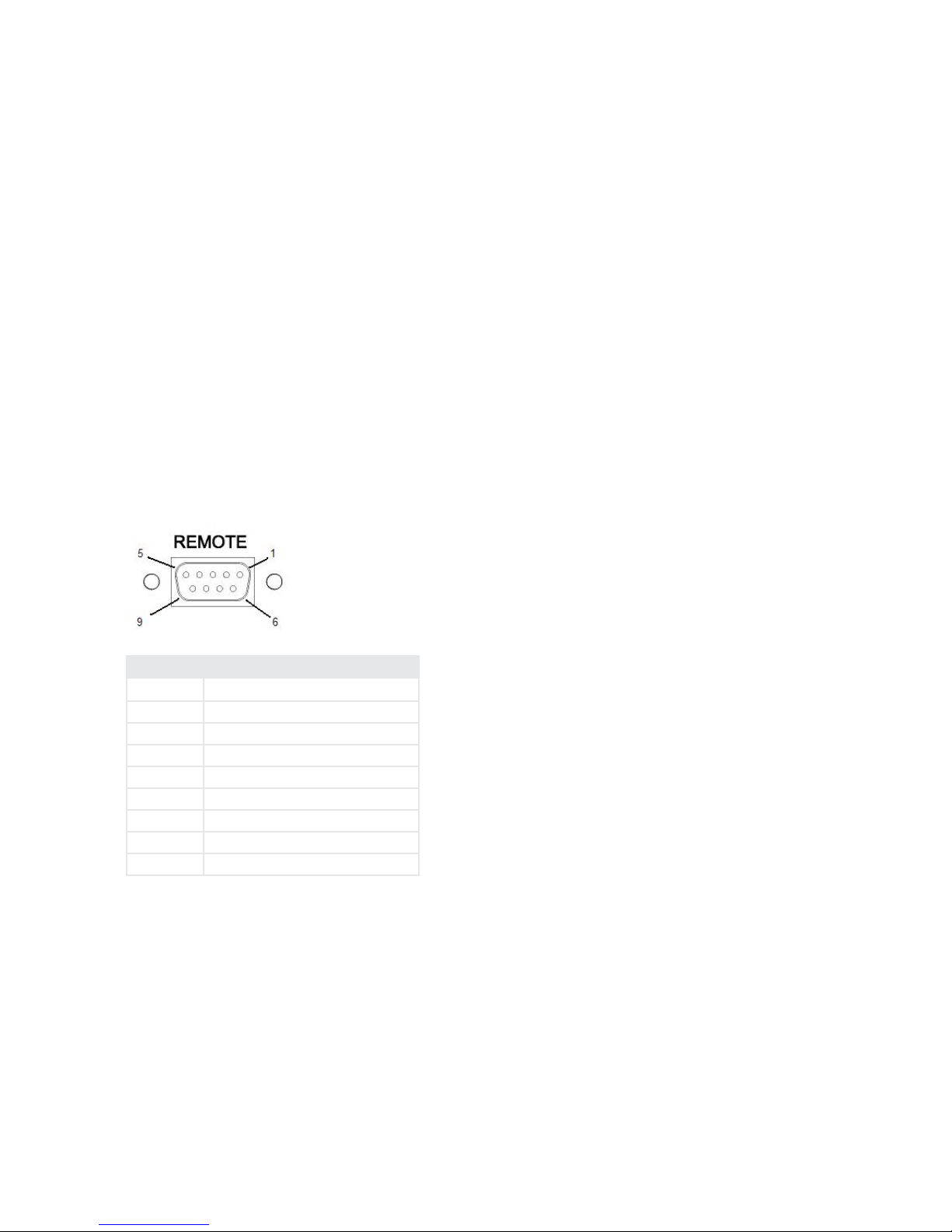
2.6 Remote Control
e female DB9 connector on the Back Panel provides access to control functions. Pin 1 of the
DB9 connector is Ground. Pins 2 through 5 on the top row are for GPIO input signals from
the remote device, while Pins 6 through 9 on the bottom row are GPIO output signals to the
remote device. Two of the GPIO input pins and two of the GPIO output pins are reserved for
each hybrid as follows:
Pin No. Function
1 GPIO Ground
2 GPIO IN Hybrid #1 - Hybrid ON
3 GPIO IN Hybrid #1 - Hybrid OFF
4 GPIO IN Hybrid #2 - Hybrid ON
5 GPIO IN Hybrid #2 - Hybrid OFF
6 GPIO OUT Hybrid #1 - ringing indicator
7 GPIO OUT Hybrid #1 - ON/OFF status indicator
8 GPIO OUT Hybrid #2 - ringing indicator
9 GPIO OUT Hybrid #2 - ON/OFF status indicator
Input Characteristics
♦ e GPIO inputs are designed to be universal. ey accept either a voltage source up
to 24VDC, or a closure to ground, which may be provided by switches, relays, or logic
outputs. In the latter case either ‘totem-pole’ or open-collector will work. e inputs are
active low.
♦ A built-in 1k Ohm pull up resistor is provided.
Output Characteristics
♦ Open-collector to ground.
♦ ese will require a pull-up resistor to drive TTL-style logic inputs. Most equipment has
the pull-up built into the input, but if there is no pull-up, you’ll have to add one, connect-

INSTALLATION | 13
ing it from the output to the +5v source on pin 8. An appropriate value is 2.2K Ohms.
♦ Sink (pull-down) current must be limited to 400mA maximum per output with total
output restricted to 1 amp (200mA each output if all ve will be used).
e GPIO output pins can be used to provide status information to other devices or warning
lamps. Outputs are available to indicate “hybrid in use” and “line ringing”.
2.7 Connecting Your Hx to other systems and non-standard lines
We know that you’re creative and that we couldn’t hope to address every possible situation that
you face, and armed with a little knowledge about how the Hx works internally, you should be
successful with most applications of the Hx.
In short: e Hx will operate on anything that electrically “looks like a POTS telephone line”.
You can connect the Hx to anything that is designed to run a standard Analog telephone set.
It needs loop current of 12-24 volts at 15-25 ma to run its line interface chip. e chip provides
telephone line audio and line signaling status (on hook/o hook/ringing/loop drop, etc) to the
processor to control the unit. If loop current isn’t present, you’ll have no audio and the Hx will
simply hang up. is is correct behavior.
Connect to PBX’s and VoIP Analog Terminal Adapters (ATA’s)
When connecting to VoIP ATA’s or PBX station ports, and even telephone company provided
“pair gain” systems and channel banks, sometimes things can be a little dierent.
Odd voltages, strange feature implementations and other issues can cause problems with audio
performance and produce weird behavior. Fortunately these kinds of interfaces keep getting
better, meaning that the Hx will probably “just work”, with a few possible exceptions.
e most common issue is likely to be what we call disconnect supervision: that is “what the
line does when the caller on the line has hung up”. Disconnect supervision is especially important if you intend to use the auto-answer feature!
When an “on-air” connected call drops, a wide range of things might happen:
♦ Most PBX’s will simply drop the audio from the outside line and perhaps send a fast
busy (or reorder) tone. e Hx will stay o hook until you manually drop it unless you’ve
set the Call Progress Tone Disconnect to disconnect after hearing reorder tone with the
internal dip switches.
♦ Some PBX’s will send a momentary loop current interruption that will cause the Hx to
release from the line (the desired behavior. Congratulations! You’re a winner!) We’ve had
good luck with PBX’s from Avaya (Larger systems). EON/Cortelco, NEC and station
disconnect supervision can be enabled in Mitel digital PBX’s though it is not by default.
Most telephone company central oce lines do support Calling Party Control (CPC) or
loop current interruption based disconnect.
♦ Most ATA’s used by VoIP providers will simply play you reorder (fast busy) tone. Most
are capable of sending the CPC loop current interruption signal, though many have this
feature disabled by default. It can usually be turned on through the web interface on the
unit. e best ones that we’ve seen are units made by Cisco/Linksys and Sipura.
♦ Some Foreign Exchange or ‘choke’ lines will not pass the CPC signal and the line will go
silent or to dial tone, a reorder, or even a recorded message. is is mainly a function of
circuit design and the selection of central oce equipment by the telephone company.

14 | Section 2
Connect to a Telos 1A2 Interface
Our earlier products, like our classic 1A2 interface didn’t support disconnect supervision
for callers “on air”. When using the Hx with a 1A2 interface, all features will work normally
though a caller selected to be “on air” who hangs up will cause the Hx to release the line (or “go
on-hook”). Audio is muted because the Hx has disconnected the line. e lamp on the switch
console and any key phones will remain lit until the line is “dropped” by the user.
You can easily build a control cable to go between the 1A2 interface and the Hx that connects
the on, o and ground signals. en plug your analog line into the “main” (hybrid #1) or “conf ”
(hybrid #2) jack on the 1A2 interface, as appropriate.
1A2 Interface DB-9 PIN Hx Hybrid DB-9 PIN
5 (#1 hybrid o) 3
9 (#1 hybrid on) 2
6 (Ground) 1
4 (#2 hybrid o) 5
3 (#2 hybrid on) 4
Connect to a Telos Direct Interface Module
Using the Hx, or any hybrid supporting disconnect supervision with the Direct Interface
Module (DIM) requires an external source of loop current. e DIM provides only a “dry”
transformer audio feed which worked well with the simpler hybrids of the time. Visit the Telos
website or contact support for several options that will allow you to use the Hx with the DIM.
Connect to other systems? Contact Telos Support
Telos collects and shares what we learn about “real world” telephony with our customers. Our
customers come up with creative ways to use our products and often create elegant solutions for
unusual problems. We’d appreciate hearing about your successes and challenges to share with
other colleagues and friends. We’re also interested in your experiences with service providers and
telecom systems and equipment vendors.
2.8 Quick Basic Test
It’s all connected, Now it’s time to check for signs of life!
First, Power the unit up and watch it complete its self test.
If the phone line is connected properly, a “dot” should be present on the display, if a minus “-” is
displayed the Hx does not detect the line voltage on the idle POTS line. Check your wiring!
If your Hx is directly connected to a phone line, press the [ON] key and dial tone should be
present on the Hx’s output and RCV bargraph.
If you have your Hx connected to a 1A2 interface, press a line key on the switch console. e
Hx should come on and dial tone should be heard on it’s output and seen on the RCV bargraph.
Pressing the ‘drop’ key should release it, and the ‘hold’ key should put the line on hold. e
display will show a minus “-” to indicate that a line is not detected. is is because the 1A2
interface only routes a line to the Hx when one is selected by the user, and is present.
Verify correct mix minus operation at this point by noting that the RCV bargraph shows the
dial tone at at a nominal level, and that the SND bargraph shows only the microphone or audio
INSTALLATION | 15
present on the device feeding the Hx SEND IN. e goal of a proper mix minus is to prevent
the hybrid from ‘hearing itself ’.
2.9 Power Input and Grounding Safety
e AC input connects mains power to the unit with a standard IEC power cord. e power
supply has a universal AC input, accepting a range from 100 to 240 VAC, 50-60 Hz, at 0.075 –
0.15 Amps.
IMPORTANT SAFETY INFORMATION
Surge Protection
Precautions should be taken to prevent damage caused by power surges.
WARNING
e Hx1 and Hx2 use a universal-input power supply, which has an internal fuse. Hazardous
voltages may still be present on some of the primary parts even when the fuse has blown.
e power cord is the primary disconnect mechanism. Mains power should be near the equipment and easily accessible. e unit should not be positioned such that access to the power cord
is impaired. If the unit is incorporated into a rack, an easily accessible safety disconnect device
should be included in the rack design.
Grounding
is equipment is designed to be operated from a power source which includes a third grounding connection in addition to the power leads. Do not defeat this safety feature. In addition to
creating a potentially hazardous situation, defeating this safety ground will prevent the internal
line noise lter from functioning.
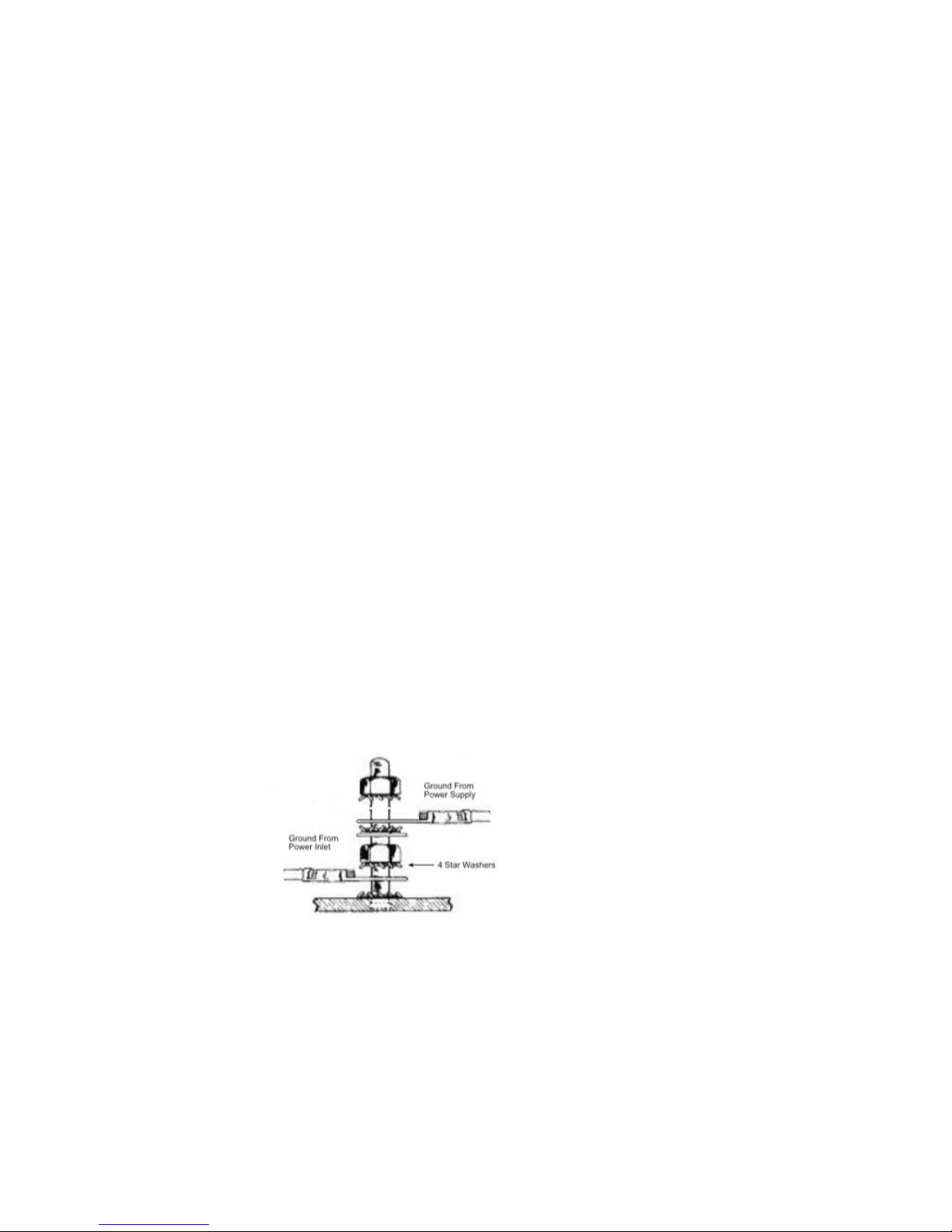
Should you replace the power supply module in the future, be sure to re-connect the safety
ground wires as shown in the illustration below.
Inside the chassis near the power inlet is a ground stud. e ground wire from the power inlet
is attached to the ground stud with a star washer on either side of the wire terminal. (See above
gure). A nut is used to independently tighten the inlet ground wire to the chassis. Next, the
ground wire from the power supply is fastened to the ground stud with a star washer on either
side of the wire terminal. An additional nut is fastened to the top of the ground stud.
 Loading...