

Page 1

Telit TRIZIUM Product Description
80264ST10007a Rev. 4– 09/09/04
T
T
Prr
ellii
T
T
P
e
R
R
o
o
I
I
d
d
t
t
Z
Z
u
u
I
U
I
U
ctt
c
M
M
D
e
D
e
s
s
crrii
c
pttii
p
o
o
n
n
DAI Telecom S.p.a. 2003 - 2004
Reproduction forbidden without DAI Telecom written authorization – All Right reserved – Right of modification reserved page 1 of 202
Page 2

Telit TRIZIUM Product Description
80264ST10007a Rev. 4– 09/09/04
Contents
1 OVERVIEW.................................................................................................................. 9
2 GENERAL PRODUCT DESCRIPTION ..................................................................... 11
2.1 Dimensions.......................................................................................................................................................11
2.2 Weight..............................................................................................................................................................12
2.3 Environmental requirements.........................................................................................................................12
2.3.1 Temperature range ....................................................................................................................................12
2.3.2 Vibration Test (non functional).................................................................................................................12
2.4 Operating Frequency......................................................................................................................................13
2.5 Transmitter output power..............................................................................................................................13
2.6 Reference sensitivity .......................................................................................................................................13
2.7 Antenna............................................................................................................................................................13
2.7.1 Antenna connector ....................................................................................................................................14
2.8 Supply voltage.................................................................................................................................................14
2.9 Power consumption.........................................................................................................................................14
2.10 Embodied Battery charger.............................................................................................................................14
2.11 User Interface..................................................................................................................................................14
2.11.1 Speech Coding..........................................................................................................................................14
2.11.2 Sim Reader................................................................................................................................................15
2.11.3 SMS ..........................................................................................................................................................15
2.11.4 Real Time Clock and Alarm .....................................................................................................................15
2.11.5 Data/fax transmission................................................................................................................................15
2.11.6 Local security management.......................................................................................................................15
2.11.7 Call control................................................................................................................................................15
2.11.8 Phonebook.................................................................................................................................................15
2.11.9 Characters management............................................................................................................................15
2.11.10 SIM related functions............................................................................................................................15
2.11.11 Call status indication.............................................................................................................................15
2.11.12 Indication of network service availability.............................................................................................16
2.11.13 Automatic answer (Voice, Data or FAX)..............................................................................................16
2.11.14 Supplementary services (SS).................................................................................................................16
2.11.15 Acoustic signaling.................................................................................................................................16
2.11.16 DTMF tones..........................................................................................................................................16
2.11.17 Buzzer output ........................................................................................................................................17
2.12 Logic level specifications ................................................................................................................................17
2.12.1 Reset signal...............................................................................................................................................18
Reproduction forbidden without DAI Telecom written authorization – All Right reserved – Right of modification reserved page 2 of 202
Page 3

Telit TRIZIUM Product Description
80264ST10007a Rev. 4– 09/09/04
2.13 RTC Bypass out...............................................................................................................................................19
2.14 Vout power output..........................................................................................................................................19
2.15 Audio levels specifications..............................................................................................................................20
2.16 Interfaces on TRIZIUM .................................................................................................................................21
2.17 Mounting the TRIZIUM on your Board.......................................................................................................23
2.17.1 General......................................................................................................................................................23
2.17.2 Module finishing & dimensions................................................................................................................23
2.17.3 Recommended foot print for application ..................................................................................................24
2.17.4 Stencil .......................................................................................................................................................24
2.17.5 Solder reflow.............................................................................................................................................25
2.17.6 Packing system..........................................................................................................................................26
2.17.7 Moisture sensibility...................................................................................................................................28
3 EVALUATION KIT..................................................................................................... 29
3.1 Evaluation Kit description .............................................................................................................................30
3.1.1 Power Supply............................................................................................................................................30
3.1.2 Serial interface ..........................................................................................................................................30
3.1.3 Audio ........................................................................................................................................................31
3.1.4 GPIO and Leds..........................................................................................................................................31
4 SERVICE AND FIRMWARE UPDATE...................................................................... 32
4.1 Step-by-Step upgrade procedure...................................................................................................................32
5 AT COMMAND.......................................................................................................... 33
5.1 Definitions........................................................................................................................................................33
5.2 AT Command Syntax .....................................................................................................................................33
5.2.1 Command lines .........................................................................................................................................33
5.2.2 Information responses and result codes ....................................................................................................35
5.2.3 Command Response Timeout ...................................................................................................................35
5.2.4 Command issuing timing ..........................................................................................................................37
5.2.5 Factory Profile and parameters stored in the profile .................................................................................37
5.3 Hayes Compliant AT Commands..................................................................................................................38
5.3.1 Generic Modem Control ...........................................................................................................................38
5.3.1.1 &F - restore factory configuration ........................................................................................................38
5.3.1.2 Z - soft reset ..........................................................................................................................................38
5.3.1.3 +FCLASS - select active service class..................................................................................................39
5.3.1.4 &Y - designate a default reset profile ...................................................................................................39
5.3.1.5 &W - store current configuration..........................................................................................................39
5.3.1.6 &Z - store telephone number in the Telit TRIZIUM module internal phonebook......................................40
5.3.1.7 &N - display internal phonebook stored numbers.................................................................................41
5.3.1.8 +GMI - request manufacturer identification .........................................................................................41
5.3.1.9 +GMM - request model identification ..................................................................................................41
5.3.1.10 +GMR - request revision identification.............................................................................................41
5.3.1.11 +GCAP - request capabilities list......................................................................................................41
5.3.1.12 +GSN - request serial number...........................................................................................................42
Reproduction forbidden without DAI Telecom written authorization – All Right reserved – Right of modification reserved page 3 of 202
Page 4

Telit TRIZIUM Product Description
80264ST10007a Rev. 4– 09/09/04
5.3.1.13 &V - display current configuration & profile....................................................................................43
5.3.1.14 &V0 - display current configuration & profile..................................................................................43
5.3.1.15 &V1 - display S registers values.......................................................................................................43
5.3.1.16 &V2 - display last connection statistics ............................................................................................45
5.3.1.17 \V - single line connect message.......................................................................................................45
5.3.1.18 %L - report line signal level..............................................................................................................46
5.3.1.19 %Q - report line quality.....................................................................................................................46
5.3.2 DTE - modem interface control ................................................................................................................47
5.3.2.1 E - command echo.................................................................................................................................47
5.3.2.2 Q - quiet resut codes..............................................................................................................................47
5.3.2.3 V- result code form...............................................................................................................................48
5.3.2.4 X - extended result codes......................................................................................................................48
5.3.2.5 I - Request identifier and software checksum.......................................................................................49
5.3.2.6 &C - data carrier detect (DCD) control.................................................................................................49
5.3.2.7 &D - data terminal ready (DTR) control...............................................................................................50
5.3.2.8 &K - flow control..................................................................................................................................50
5.3.2.9 &S - data set ready (DSR) control ........................................................................................................50
5.3.2.10 \R - ring (RI) control.........................................................................................................................52
5.3.2.11 +IPR - fixed DTE interface rate........................................................................................................52
5.3.2.12 +IFC - DTE - DTA flow control.......................................................................................................52
5.3.2.13 +ILRR - DTE - modem rate reporting ..............................................................................................54
5.3.2.14 +ICF - DTE - modem character format.............................................................................................55
5.3.3 Call Control...............................................................................................................................................56
5.3.3.1 D - dial ..................................................................................................................................................56
5.3.3.2 T - set tone dial......................................................................................................................................58
5.3.3.3 P - set pulse dial....................................................................................................................................58
5.3.3.4 A - answer.............................................................................................................................................58
5.3.3.5 A/ - Last command automatic repetition...............................................................................................58
5.3.3.6 H - disconnect .......................................................................................................................................59
5.3.3.7 O - return to On Line Mode ..................................................................................................................60
5.3.3.8 &G - guard tone ....................................................................................................................................60
5.3.3.9 &P - pulse dial make/break ratio...........................................................................................................61
5.3.4 Modulation control....................................................................................................................................61
5.3.4.1 +MS - modulation control .....................................................................................................................61
5.3.4.2 %E - enable/disable line quality monitor and auto retrain or fallback / fallforward .............................62
5.3.5 Compression control .................................................................................................................................63
5.3.5.1 +DS - set data compression...................................................................................................................63
5.3.5.2 +DR - data compression reporting........................................................................................................63
5.3.6 Break control.............................................................................................................................................64
5.3.6.1 \B - transmit break to remote.................................................................................................................64
5.3.6.2 \K - break handling................................................................................................................................64
5.3.7 S parameters..............................................................................................................................................65
5.3.7.1 S0 - number of rings to auto answer .....................................................................................................65
5.3.7.2 S1 - ring counter....................................................................................................................................65
5.3.7.3 S2 - escape character.............................................................................................................................66
5.3.7.4 S3 - carriage return character................................................................................................................66
5.3.7.5 S4 - line feed character..........................................................................................................................67
5.3.7.6 S5 - backspace character.......................................................................................................................67
5.3.7.7 S7 - wait time for carrier, silence or dial tone.......................................................................................68
5.3.7.8 S10 - lost carrier to hang up delay.........................................................................................................68
5.3.7.9 S12 - escape prompt delay....................................................................................................................69
5.3.7.10 S25 - delay to DTR off......................................................................................................................69
5.3.7.11 S30 - disconnect inactivity timer.......................................................................................................70
5.3.7.12 S38 - delay before forced hang up ....................................................................................................70
5.4 ETSI GSM 07.07 AT Commands ..................................................................................................................71
5.4.1 General......................................................................................................................................................71
Reproduction forbidden without DAI Telecom written authorization – All Right reserved – Right of modification reserved page 4 of 202
Page 5

Telit TRIZIUM Product Description
80264ST10007a Rev. 4– 09/09/04
5.4.1.1 +CGMI - request manufacturer identification.......................................................................................71
5.4.1.2 +CGMM - request model identification ................................................................................................71
5.4.1.3 +CGMR - request revision identification ..............................................................................................71
5.4.1.4 +CGSN - request product serial number identification .........................................................................71
5.4.1.5 +CSCS - select TE character set ...........................................................................................................71
5.4.1.6 +CIMI - request international mobile subscriber identity (IMSI).........................................................73
5.4.2 Call control................................................................................................................................................74
5.4.2.1 +CBST - select bearer service type.......................................................................................................74
5.4.2.2 +CRLP - radio link protocol .................................................................................................................75
5.4.2.3 +CR - service reporting control............................................................................................................76
5.4.2.4 +CEER - extended error report.............................................................................................................77
5.4.2.5 +CRC - cellular result codes.................................................................................................................78
5.4.3 Network service handling .........................................................................................................................79
5.4.3.1 +CNUM - subscriber number................................................................................................................79
5.4.3.2 +CREG - network registration report....................................................................................................80
5.4.3.3 +COPS - operator selection...................................................................................................................82
5.4.3.4 +CLCK - facility lock/ unlock ..............................................................................................................83
5.4.3.5 +CPWD - change facility password......................................................................................................83
5.4.3.6 +CLIP - calling line identification presentation....................................................................................85
5.4.3.7 +CLIR - calling line identification restriction.......................................................................................86
5.4.3.8 +CCFC - call forwarding number and conditions.................................................................................87
5.4.3.9 +CCWA - call waiting ..........................................................................................................................89
5.4.3.10 +CHLD - call holding services..........................................................................................................89
5.4.3.11 +CUSD - unstructured supplementary service data ..........................................................................91
5.4.3.12 +CAOC - advice of charge................................................................................................................92
5.4.3.13 +CLCC - list current calls ................................................................................................................93
5.4.3.14 +CSSN – SS Notification..................................................................................................................93
5.4.3.15 +CCUG – Closed User Group supplementary service control............................................................95
5.4.4 Mobile Equipment control ........................................................................................................................96
5.4.4.1 +CPAS - phone activity status .............................................................................................................96
5.4.4.2 +CFUN Set phone functionality (Power Saving Management)............................................................96
5.4.4.3 +CPIN - enter PIN.................................................................................................................................98
5.4.4.4 +CSQ- signal quality.............................................................................................................................99
5.4.4.5 +CPBS - select phonebook memory storage.......................................................................................100
5.4.4.6 +CPBR - read phonebook entries........................................................................................................101
5.4.4.7 +CPBF - find phonebook entries.........................................................................................................102
5.4.4.8 +CPBW - write phonebook entry........................................................................................................103
5.4.4.9 +CCLK - Clock Management.............................................................................................................104
5.4.4.10 +CALA - Alarm Management ........................................................................................................105
5.4.4.11 +CALM - alert sound mode............................................................................................................107
5.4.4.12 +CRSL - ringer sound level ............................................................................................................107
5.4.4.13 +CLVL - loudspeaker volume level................................................................................................107
5.4.4.14 +CMUT - microphone mute control ...............................................................................................108
5.4.4.15 +CACM - accumulated call meter ..................................................................................................109
5.4.4.16 +CAMM - accumulated call meter maximum.................................................................................109
5.4.4.17 +CPUC - price per unit and currency table.....................................................................................109
5.4.5 Mobile equipment errors.........................................................................................................................111
5.4.5.1 +CMEE - report mobile equipment error............................................................................................111
5.4.5.2 +CME ERROR: - ME error result code..............................................................................................112
5.4.6 Voice Control (TIA IS-101)....................................................................................................................113
5.4.6.1 +VTS: - DTMF tones transmission.....................................................................................................113
5.4.7 Commands For GPRS.............................................................................................................................114
5.4.7.1 +CGACT - PDP context activate or deactivate...................................................................................114
5.4.7.2 +CGATT - GPRS attach or detach......................................................................................................115
5.4.7.3 +CGDATA - Enter data state..............................................................................................................116
5.4.7.4 +CGDCONT - define PDP context.....................................................................................................117
5.4.7.5 +CGPADDR - show PDP address ......................................................................................................117
Reproduction forbidden without DAI Telecom written authorization – All Right reserved – Right of modification reserved page 5 of 202
Page 6

Telit TRIZIUM Product Description
80264ST10007a Rev. 4– 09/09/04
5.4.7.6 +CGREG - GPRS network registration status ....................................................................................119
5.4.7.7 +CGQMIN - quality of service profile (minimum acceptable)...........................................................119
5.4.7.8 +CGQREQ - quality of service profile (requested).............................................................................121
5.4.8 Commands For Battery Charger .............................................................................................................122
5.4.8.1 +CBC - Battery Charge.......................................................................................................................122
5.5 ETSI GSM 07.05 AT Commands for SMS and CB services.....................................................................123
5.5.1 General configuration .............................................................................................................................123
5.5.1.1 +CSMS - select message service.........................................................................................................123
5.5.1.2 +CPMS - preferred message storage...................................................................................................124
5.5.1.3 +CMGF - message format...................................................................................................................125
5.5.1.4 +CSMP – Set parameters in text mode ...............................................................................................125
5.5.1.5 +CSDH – Show parameters in text mode ...........................................................................................125
5.5.1.6 +CSAS – Save setting text mode ........................................................................................................126
5.5.1.7 +CRES – Restore text mode settings ..................................................................................................126
5.5.1.8 +CSCB – Select Cell Broadcast Message types..................................................................................127
5.5.1.9 +CMS ERROR - message service failure result code.........................................................................128
5.5.2 Message configuration ............................................................................................................................129
5.5.2.1 +CSCA - service center address..........................................................................................................129
5.5.3 Message receiving and reading ...............................................................................................................130
5.5.3.1 +CNMI - new message indications to Terminal Equipment...............................................................130
5.5.3.2 +CMGL - list messages.......................................................................................................................133
5.5.3.3 +CMGR - read message......................................................................................................................135
5.5.4 Message sending and writing..................................................................................................................137
5.5.4.1 +CMGS - send message......................................................................................................................137
5.5.4.2 +CMSS - send message from storage .................................................................................................137
5.5.4.3 +CMGW - write message to memory................................................................................................139
5.5.4.4 +CMGD - delete message...................................................................................................................139
5.6 Custom AT Commands................................................................................................................................141
5.6.1 General configuration .............................................................................................................................141
5.6.1.1 #CGMI - request manufacturer identification.....................................................................................141
5.6.1.2 #CGMM - request model identification..............................................................................................141
5.6.1.3 #CGMR - request revision identification............................................................................................141
5.6.1.4 #CGSN - request product serial number identification.......................................................................141
5.6.1.5 #CIMI - request international mobile subscriber identity (IMSI) .......................................................142
5.6.1.6 #CAP - Change Audio Path ................................................................................................................142
5.6.1.7 #SRS - Select ringer sound .................................................................................................................143
5.6.1.8 #SRP –Select Ringer Path...................................................................................................................144
5.6.1.9 #STM - Signalling Tones Mode..........................................................................................................145
5.6.1.10 #PCT – display PIN Counter...........................................................................................................145
5.6.1.11 #SHDN – Software Shut Down ......................................................................................................146
5.6.1.12 #WAKE – Wake from Alarm mode................................................................................................147
5.6.1.13 #QTEMP –Query Temperature overflow........................................................................................148
5.6.1.14 #SGPO –Set General Purpose Output.............................................................................................149
5.6.1.15 #GGPI – Read General Purpose Input ............................................................................................150
5.6.1.16 #GPIO –General Purpose Input/Output pin control........................................................................151
5.6.1.17 #ADC – Read Analog/Digital Converter input ...............................................................................153
5.6.1.18 #MONI – Monitor Cells..................................................................................................................154
5.6.1.19 #QSS – Query SIM Status...............................................................................................................154
5.6.1.20 #ACAL – Set Automatic Call .........................................................................................................156
5.6.1.21 #SMOV – SMS Overflow...............................................................................................................157
5.6.1.22 #SHFEC – Set Handsfree echo canceller........................................................................................157
5.6.1.23 #HFMICG – Handsfree Microphone Gain......................................................................................158
5.6.1.24 #HSMICG – Handset Microphone Gain.........................................................................................158
5.6.1.25 #SHFSD – Set Handsfree side tone.................................................................................................158
5.6.1.26 #/ – Repeat last command ...............................................................................................................159
Reproduction forbidden without DAI Telecom written authorization – All Right reserved – Right of modification reserved page 6 of 202
Page 7

Telit TRIZIUM Product Description
80264ST10007a Rev. 4– 09/09/04
5.6.1.27 #BND – Select Band (DCS 1800 or PCS 1900) ............................................................................160
5.7 FAX Class 1 Commands...............................................................................................................................161
5.7.1 General configuration .............................................................................................................................161
5.7.1.1 +FCLASS - select active service class................................................................................................161
5.7.1.2 +FMI – Report manufacturer ID.........................................................................................................162
5.7.1.3 +FMM? – Report model ID ................................................................................................................162
5.7.1.4 +FMR – Report revision ID................................................................................................................163
5.7.2 Transmission/Reception control..............................................................................................................163
5.7.2.1 +FTS – Stop Transmission and pause.................................................................................................163
5.7.2.2 +FRS – Wait for receive silence .........................................................................................................164
5.7.2.3 +FTM – Transmit data modulation.....................................................................................................164
5.7.2.4 +FRM – Receive data modulation ......................................................................................................164
5.7.2.5 +FTH – Transmit data with HDLC framing .......................................................................................165
5.7.2.6 +FRH – Receive data with HDLC framing.........................................................................................166
5.7.3 Serial port control ...................................................................................................................................166
5.7.3.1 +FLO – Select flow control specified by type ....................................................................................166
5.7.3.2 +FPR – Select serial port rate..............................................................................................................166
5.7.3.3 +FDD – Double escape character replacement control.......................................................................167
5.8 Easy GPRS Extension...................................................................................................................................168
5.8.1 Overview .................................................................................................................................................168
5.8.2 Easy GPRS definition .............................................................................................................................168
5.8.2.1 Configuring the GPRS access.............................................................................................................169
5.8.2.2 Configuring the embedded TCP/IP stack............................................................................................169
5.8.2.3 Defining the Internet peer to be contacted ..........................................................................................169
5.8.2.4 Open the connection with the internet host.........................................................................................169
5.8.2.5 Close the Socket and deactivate the context .......................................................................................169
5.8.3 Known limitations...................................................................................................................................169
5.8.4 Easy GPRS custom AT command Definition.........................................................................................170
5.8.4.1 #USERID – Authentication User ID control.......................................................................................170
5.8.4.2 #PASSW – Authentication Password control.....................................................................................171
5.8.4.3 #PKTSZ –Packet Size control.............................................................................................................172
5.8.4.4 #DSTO – Data Sending Timeout control............................................................................................173
5.8.4.5 #SKTTO – Socket inactivity timeout control......................................................................................174
5.8.4.6 #SKTSET – Socket definition control ................................................................................................175
5.8.4.7 #SKTOP – Socket Open command.....................................................................................................176
5.8.4.8 #QDNS – Query DNS.........................................................................................................................176
5.8.4.9 #SKTSAV – Socket Parameters Save Command ...............................................................................176
5.8.4.10 #SKTRST – Socket Parameters Reset Command...........................................................................178
5.9 Easy Camera Extension................................................................................................................................179
5.9.1 Camera management...............................................................................................................................179
5.9.1.1 #CAMON – Camera ON....................................................................................................................179
5.9.1.2 #CAMOFF – Camera OFF.................................................................................................................179
5.9.1.3 #TPHOTO – Camera Take Photo.......................................................................................................180
5.9.1.4 #RPHOTO – Camera Read Photo.......................................................................................................180
5.9.1.5 #OBJL – Object List ...........................................................................................................................181
5.9.1.6 #OBJR – Object Read.........................................................................................................................181
5.9.1.7 #CAMQUA – Camera Select Quality of Photo ..................................................................................182
5.9.1.8 #CMODE – Camera Select Operating MODE....................................................................................183
5.9.2 Email management ..................................................................................................................................184
5.9.2.1 #ESMTP – Email SMTP server..........................................................................................................184
5.9.2.2 #EADDR – Email sender address.......................................................................................................185
5.9.2.3 #EUSER – Email authentication USER NAME.................................................................................186
5.9.2.4 #EPASSW – Email authentication PASSWORD ...............................................................................187
5.9.2.5 #SEMAIL - Send Email......................................................................................................................188
Reproduction forbidden without DAI Telecom written authorization – All Right reserved – Right of modification reserved page 7 of 202
Page 8

Telit TRIZIUM Product Description
80264ST10007a Rev. 4– 09/09/04
5.10 Easy Scan Extension .....................................................................................................................................189
5.10.1 Easy Scan custom AT commands...........................................................................................................189
5.10.1.1 *CSURV - Network Survey of the complete 900/1800/1900 Network ..........................................189
5.10.1.2 *CSURVC - Network Survey in computer friendly format............................................................191
5.10.1.3 *CSURVU - Network Survey of user defined 900/1800/1900 channels ........................................192
5.10.1.4 *CSURVUC - Network Survey in computer friendly format.........................................................193
5.11 Jammed Detect & Report Extension...........................................................................................................194
5.11.1 Overview.................................................................................................................................................194
5.11.2 Jammed Detect & Report custom AT commands...................................................................................194
5.11.2.1 #JDR - Jammed Detect & Report ....................................................................................................194
6 CONFORMITY ASSESSMENT ISSUES................................................................ 196
6.1 TRIZIUM: Conformity Assessment............................................................................................................197
6.2 TRIZIUM: FCC Equipment Authorization...............................................................................................198
7 TRIZIUM TECHNICAL SUPPORT........................................................................... 199
8 LIST OF ACRONYMS ............................................................................................. 200
9 DOCUMENT CHANGE LOG................................................................................... 202
Reproduction forbidden without DAI Telecom written authorization – All Right reserved – Right of modification reserved page 8 of 202
Page 9

1 Overview
Telit TRIZIUM Product Description
80264ST10007a Rev. 4– 09/09/04
Aim of this document is the description of features, functions and interfaces of the Telit TRIZIUM
modules.
The Telit TRIZIUM modules are small, lightweight and low power consumption devices that allow
digital communication services wherever a GSM 900, DCS 1800, PCS1900 network is present.
Based on the long experience of the Telit GM862 module family; TRIZIUM modules are the low cost
connector-less best solution for medium to high quantity project. Moreover, customer with
experience in Telit GM862 module family can take advantage of that thank to the SW high backward
compatibility.
The Telit TRIZIUM module includes features like GPRS, Voice, Circuit Switch Data transfer, Fax,
Phonebook and SMS support, ‘Easy GPRS’ embedded TCP/IP stack and ‘EASY CAMERA’,
battery charging capabilities
It is specifically designed and developed by Telit for OEM usage and dedicated to portable data,
voice and telematics applications needing the added triband and GPRS Class 10 improved speed
features and the battery charger such as:
q Fast Worldwide GPRS Telemetry and Telecontrol (SCADA applications)
q Worldwide Smart GPRS Security systems
q Worldwide Smart GPRS Vending machines
q Fast Worldwide GPRS POS terminals
q Worldwide PDAs
q Worldwide Phones and Payphones
q Worldwide Smart Automotive and Fleet Management applications
q Battery powered applications needing a battery charger
The Telit TRIZIUM modules will evolve in future in order to face the competitive
telecommunication market requirements supporting the new incoming standards:
q Bluetooth support
q GPS embedded functionality
In order to meet the competitive OEM and vertical market stringent requirements, Telit supports its
customers with a dedicated TRIZIUM
q an Evaluation Kit to help you develop you application;
q a dedicated Website (www.TRIZIUM.com) with all updated information available;
Module Support Policy with:
Reproduction forbidden without DAI Telecom written authorization – All Right reserved – Right of modification reserved page 9 of 202
Page 10

Telit TRIZIUM Product Description
80264ST10007a Rev. 4– 09/09/04
q
q a high level specialist technical support to assist you in your development;
q free SW releases upgrade download (via the Website) every time a new functionality will be
added to the Telit modules SW.
For more updated information concerning product Roadmap and availability, technical
characteristics, commercial and other issues please check the Telit TRIZIUM modules dedicated
Website www.TRIZIUM.com or mail to:
ts-trizium@telit.net, for any Technical information or support you may need
ci-trizium@telit.net, for any Commercial, sales or marketing related info
af-trizium@telit.net , for After Sales issues
NOTE: Some of the performances of the Telit TRIZIUM modules depend on SW version
installed on the module itself. In particular on Chapter 5, dedicated to the supported AT
commands, the minimum SW version required to support each specific AT command is
reported.
The Telit TRIZIUM modules SW group is continuously working in order to add new features
and improve the overall performances. From time to time that a new SW version is released, it
will be freely distributed by the Telit TRIZIUM module dedicated Website
The Telit TRIZIUM modules are easily upgradeable by the developer using the Telit TRIZIUM
module Flash Programmer.
For more info about this topic (and not only !) please check Telit TRIZIUM modules dedicated
Website www.TRIZIUM.com. and www.telit.net
Reproduction forbidden without DAI Telecom written authorization – All Right reserved – Right of modification reserved page 10 of 202
Page 11

Telit TRIZIUM Product Description
80264ST10007a Rev. 4– 09/09/04
2 General Product Description
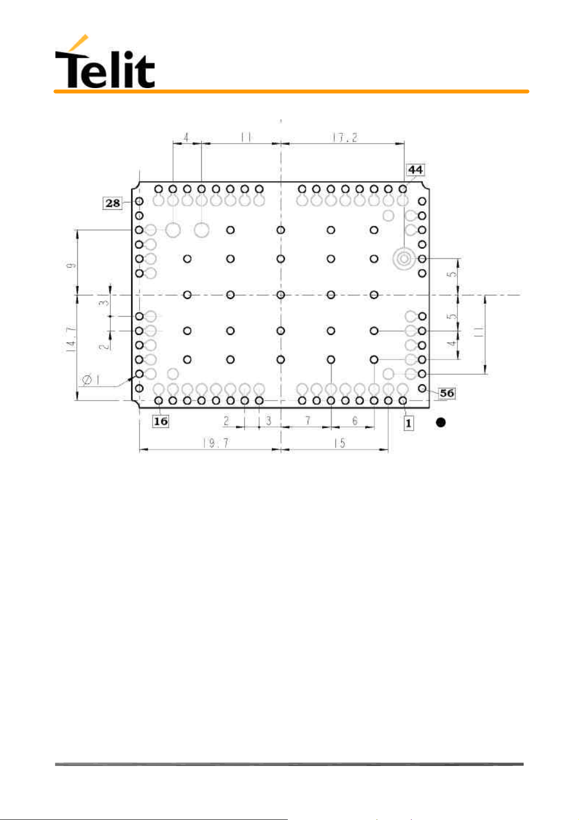
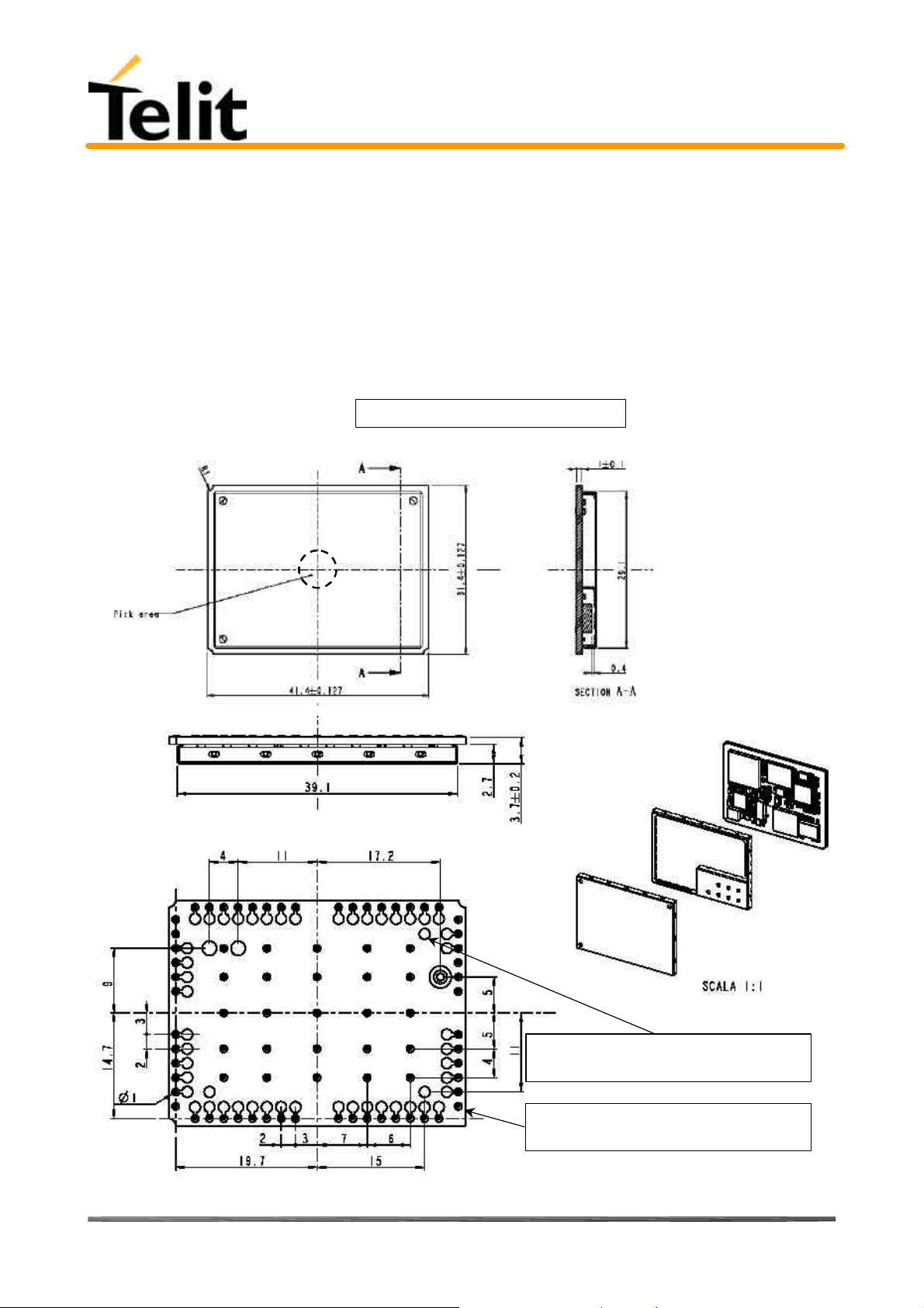
2.1 Dimensions
The Telit TRIZIUM module overall dimension are:
• Lenght: 41,4 mm
• Width: 31,4 mm
• Thickness: 3,6 mm
The layout of Telit TRIZIUM module is shown in the following figure:
Reproduction forbidden without DAI Telecom written authorization – All Right reserved – Right of modification reserved page 11 of 202
Page 12
Telit TRIZIUM Product Description
80264ST10007a Rev. 4– 09/09/04
Bottom View
2.2 Weight
The Telit TRIZIUM module weight is 9 gr.
2.3 Environmental requirements
The Telit TRIZIUM module is compliant with the applicable ETSI reference documentation GSM 05.05 Release1999
ETSI EN300910 V8.4.1
2.3.1 Temperature range
• Temperature in normal functional conditions –10°C ÷ +55°C
• Temperature in extreme functional conditions* –25°C ÷ +75°C
• Temperature in storage conditions –30°C ÷ +85°C
*these temperature can affect the sensitivity and performance of the module
2.3.2 Vibration Test (non functional)
• 10 ÷12Hz ASD = 1.92m 2 /s 3
• 12 ÷ 150Hz –3dB/oct
Reproduction forbidden without DAI Telecom written authorization – All Right reserved – Right of modification reserved page 12 of 202
Page 13

Telit TRIZIUM Product Description
80264ST10007a Rev. 4– 09/09/04
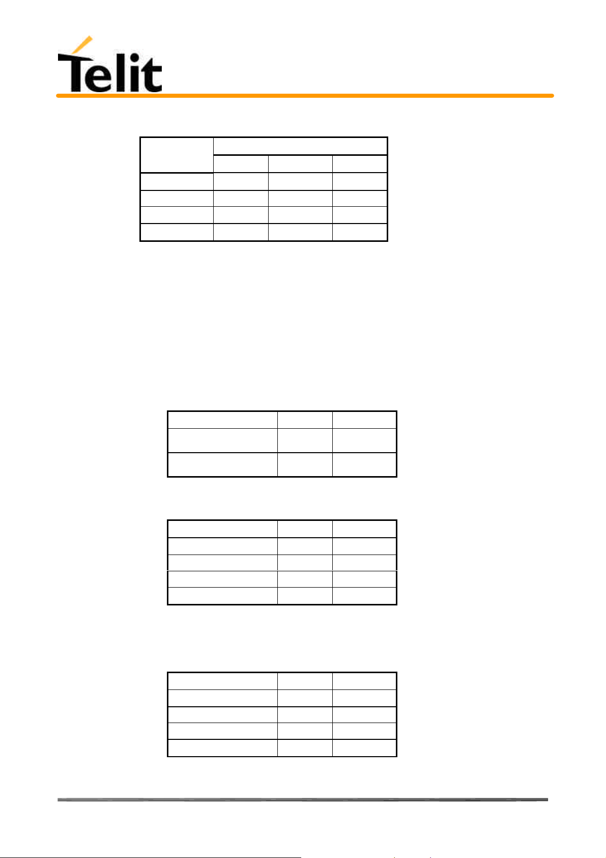
2.4 Operating Frequency
The operating frequencies in GSM, DCS, PCS modes are conform to the GSM specifications.
Mode Freq. TX (MHz) Freq. RX (MHz) Channels (ARFC) TX - RX offset
E-GSM-900 890.0 - 914.8 935.0 - 959.8 0 – 124 45 MHz
880.2 - 889.8 925.2 - 934.8 975 - 1023
DCS-1800 1710.2 - 1784.8 1805.2 - 1879.8 512 – 885 95 MHz
PCS-1900 1850.2 - 1909.8 1930.2 - 1989.8 512 - 810 80 MHz
2.5 Transmitter output power
GSM–900
The Telit TRIZIUM transceiver module in GSM–900 operating mode are of class 4 in accordance with the specification
which determine the nominal 2W peak RF power (+33dBm) on 50 Ohm.
DCS–1800
The Telit TRIZIUM transceiver module in DCS–1800 operating mode are of class 1 in accordance with the specifications
which determine the nominal 1W peak RF power (+30dBm) on 50 Ohm.
PCS–1900
The Telit TRIZIUM transceiver module in PCS–1900 operating mode are of class 1 in accordance with the specifications
which determine the nominal 1W peak RF power (+30dBm) on 50 Ohm.
2.6 Reference sensitivity
GSM–900
The sensitivity of the Telit TRIZIUM transceiver module according to the specifications for the class 4 GSM–900
portable terminals is better than –102dBm in all the operational conditions.
DCS–1800
The sensitivity of the Telit TRIZIUM transceiver module according to the specifications for the class 1 portable terminals
GSM 1800 is better than –102dBm in normal operating conditions.
PCS–1900
The sensitivity of the Telit TRIZIUM transceiver module according to the specifications for the class 1 portable terminals
PCS 1900 is better than –102dBm in normal operating conditions.
2.7 Antenna
The antenna that the customer chooses to use, depending on his application, should fulfil the
following requirements:
Frequency range
Bandwith
Gain
Impedance
Input power
VSWR absolute max
VSWR recommended
Standard Dual Band frequency range,
Standard Tri Band frequency range
80 MHz in GSM & 170 MHz in DCS & 140 MHz
PCS band
> 0 dBi; < 3 dBi
50 ohm
> 2 W peak power
<= 10:1
<= 2:1
Reproduction forbidden without DAI Telecom written authorization – All Right reserved – Right of modification reserved page 13 of 202
Page 14

Telit TRIZIUM Product Description
80264ST10007a Rev. 4– 09/09/04
2.7.1 Antenna connector
N/A
2.8 Supply voltage
The external power supply must be connected to VBATT signal (see paragraph 2.16,) and must fulfil the following
requirements:
• Nominal operating voltage 3.8 V
• Operating voltage range 3.4 V - 4.2 V
Note: Operating voltage range must never be exceeded, care must be taken in order to fulfill min/max voltage
requirements.
2.9 Power consumption
The typical current consumption of the Telit TRIZIUM module are:
• Power off current (typical) < 30 µA;
• Stand–by current < 19 mA
• Operating current in voice ch. 170 mA
• Operating current in voice ch. < 270 mA
• Operating current in GPRS class 10 < 500 mA
(< 4 mA
rms
@ typical network conditions
rms
1.9 A
rms
@ typical network conditions
rms
using command AT+CFUN )
rms
@ worst network conditions
peak
2.10 Embodied Battery charger
The battery charger is suited for 3.7V Li-Ion rechargeable battery (suggested capacity 500-1000mAH). The Charger
needs only a CURRENT LIMITED power source input and charges the battery directly through VBATT connector
pins.
• Battery charger input pin CHARGE
• Battery pins VBATT, GND
• Battery charger input voltage min 5.0 V
• Battery charger input voltage typ 5.5 V
• Battery charger input voltage max 7.0 V
• Battery charger input current max 400mA
• Battery type Li-Ion rechargeable
NOTE: If embodied battery charger is used, then a LOW ESR capacitor of at least 100µF must be mounted in parallel
to VBATT TRIZIUM pins.
NOTE: when power is supplied to the CHARGE pin, a battery must always be connected to the VBATT pins of the
TRIZIUM.
2.11 User Interface
The user interface is managed by AT commands specified on the GSM 07.07 and 07.05 specification and listed in the
chapter 5, AT Command.
2.11.1 Speech Coding
The Telit TRIZIUM modules vocoder supports the following rates:
• Half Rate.
• Full rate,
• Enhanced Full Rate
Reproduction forbidden without DAI Telecom written authorization – All Right reserved – Right of modification reserved page 14 of 202
Page 15

Telit TRIZIUM Product Description
80264ST10007a Rev. 4– 09/09/04
2.11.2 Sim Reader
The Telit TRIZIUM modules support phase 2 GSM11.14 - SIM 3V volts ONLY with and external SIM connector. For 5V
SIM operation an external level translator can be added.
2.11.3 SMS
The Telit TRIZIUM module supports the following SMS types:
Mobile Terminated (MT) class 0 – 2 with signaling of new incoming SMS, SIM full, SMS read
Mobile Originated class 0 – 3 with writing, memorize in SIM and sending
Cell Broadcast compatible with CB DRX with signaling of new incoming SMS.
2.11.4 Real Time Clock and Alarm
The Telit TRIZIUM module supports the Real Time Clock and Alarm functions through AT commands, furthermore an
alarm output pin (GPIO6) can be configured to indicate the alarm with a hardware line output.
Furthermore the Voltage Output of the RTC power supply is provided so that a backup capacitor can be added to
increase the RTC autonomy.
2.11.5 Data/fax transmission
The Telit TRIZIUM module supports:
• Packed Data transfer GPRS Class B, Multislot Class 10
• Data transmission according to the GSM 07.07, 07.05
• CSD up to 14.4 Kbps
• Fax service, Class 1 Group 3
• Fax service, Class 2 Group 3 (future SW release)
2.11.6 Local security management
With lock of Subscriber Identity module (SIM), and security code request at power–up.
2.11.7 Call control
Call cost control function.
2.11.8 Phonebook
Function available to store the telephone numbers in SIM memory.
Capability depends on SIM version/memory
2.11.9 Characters management
Availability of lowercase, uppercase and IRA characters. (international reference alphabet)
In SMS PDU mode all character set are supported.
2.11.10 SIM related functions
Activation/deactivation of the numbers stored in phone book FDN, ADN and PINs. Extension at the PIN2 for the PUK2
insertion capability for lock condition.
2.11.11 Call status indication
By AT commands.
Reproduction forbidden without DAI Telecom written authorization – All Right reserved – Right of modification reserved page 15 of 202
Page 16

Telit TRIZIUM Product Description
80264ST10007a Rev. 4– 09/09/04
2.11.12 Indication of network service availability
By AT commands and LED indication on dedicated output.
The STAT_LED is an Open Collector output where it is possible to directly connect a LED to show information on the
network service availability and Call status.
STAT_LED indications
LED status Device Status
permanently off device off
fast blinking
(period 1s, Ton 0,5s)
slow blinking
(period 3s, Ton 0,3s)
Permanently on a call is active
Net search / Not
registered / turning off
Registered full service
2.11.13 Automatic answer (Voice, Data or FAX)
After n (depends of settings) rings automatically answers with beep (see S0 param).
2.11.14 Supplementary services (SS)
• Call Barring,
• Call Forwarding,
• Calling Line Identification Presentation (CLIP),
• Calling Line Identification Restriction (CLIR),
• Call Waiting, other party call Waiting Indication,
• Call Hold, other party Hold / Retrieved Indication,
• Closed User Group supplementary service (CUG),
• Advice of Charge,
• Unstructured SS Mobile Originated (MO)
2.11.15 Acoustic signaling
The acoustic signalling of Telit TRIZIUM module on the selected acoustic device are the following:
• Call waiting;
• Ringing tone;
• SMS received tone;
• Busy tone;
• Power on/off tone;
• Off Hook dial tone;
• Congestion tone;
• Connected tone;
• Call dropped;
• No service tone;
• Alarm tone.
2.11.16 DTMF tones
DTMF tones managed by specific AT commands.
These tones are generated with AT commands only during voice calls.
Reproduction forbidden without DAI Telecom written authorization – All Right reserved – Right of modification reserved page 16 of 202
Page 17
Telit TRIZIUM Product Description
80264ST10007a Rev. 4– 09/09/04
The minimum duration of a DTMF tone is 100 ms.
Group high
Group low
697 Hz 1 2 3
770 Hz 4 5 6
852 Hz 7 8 9
941 Hz * 0 #
1209 Hz 1336 Hz 1477 Hz
2.11.17 Buzzer output
The General Purpose I/O pin GPIO7 can be configured to output the BUZZER output signal, with only an external
Mosfet/transistor and a diode a Buzzer can be directly driven.
The ringing tone and the other signaling tones can be redirected to this Buzzer output with a specific AT command.
2.12 Logic level specifications
Where not specifically stated, all the interface circuits work at 2.8V CMOS logic levels.
The following table shows the logic level specifications used in the Telit TRIZIUM module interface circuits:
Absolute Maximum Ratings -Not Functional
Parameter Min Max
Input level on any digital
pin when on
Input voltage on analog
pins when on
Operating Range - Interface levels (2.8V CMOS)
Level Min Max
Input high level 2.1V 3.3V
Input low level 0V 0.5V
Output high level 2.2V 3.0V
Output low level 0V 0.35V
-0.3V +3.75V
-0.3V +3.0 V
For 2,0V signals:
Operating Range - Interface levels (2.0V CMOS)
Level Min Max
Input high level 1.6V 3.3V
Input low level 0V 0.4V
Output high level 1,65V 2.2V
Output low level 0V 0.35V
Reproduction forbidden without DAI Telecom written authorization – All Right reserved – Right of modification reserved page 17 of 202
Page 18

Telit TRIZIUM Product Description
80264ST10007a Rev. 4– 09/09/04
2.12.1 Reset signal
Signal Function I/O Pin
RESET Phone reset I/O 23 (connector SO301)
RESET is used to reset the Telit TRIZIUM module. Whenever this signal is pulled low, the TRIZIUM
is reset. When the device is reset it stops any operation and after the release of the reset it shuts
down, without doing any detach operation from the network where it is registered to. This behavior
is not a proper shut down because any GSM device is requested to issue a detach request on turn
off. For this reason the Reset signal must not be used to normally shutting down the device, but
only as an emergency exit in the rare case the device remains stucked waiting for some network
response.
The RESET is internally controlled on start-up to achieve always a proper power-on reset sequence,
so there's no need to control this pin on start-up. It may only be used to reset a device already on
that is not responding to any command.
NOTE: do not use this signal to power off the Telit TRIZIUM module. Use the ON/OFF signal
(Pin 17 of SO301) to perform this function or the AT#SHDN command.
Reset Signal Operating levels:
Signal Min Max
RESET Input high 2.2V* 3.3V
RESET Input low 0V 0.2V
* this signal is internally pulled up so the pin can be left floating if not used.
If unused, this signal may be left unconnected. If used, then it must always be connected with an open collector
transistor, to permit to the internal circuitry the power on reset and undervoltage lockout functions.
Reproduction forbidden without DAI Telecom written authorization – All Right reserved – Right of modification reserved page 18 of 202
Page 19
Telit TRIZIUM Product Description
80264ST10007a Rev. 4– 09/09/04
2.13 RTC Bypass out
The PIN VRTC brings out the Real Time Clock supply which is separate from the rest of the digital part, allowing to
have only RTC going on when all the other parts of the device are off.
To this power output a backup capacitor can be added in order to increase the RTC autonomy during power off of the
battery. NO Devices must be powered from this pin.
2.14 Vout power output
A regulated power supply output is provided in order to supply small devices from module.
This output is active when the module is ON and goes off when module is shut down.
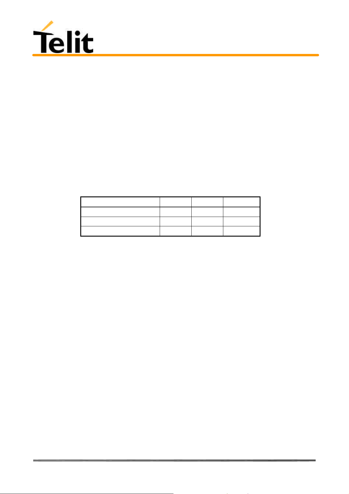
The operating range characteristics of the supply are:
Operating Range - Vout power supply
Min Typ Max
Output voltage 2.75V 2.85V 2.95V
Output current 100mA
Output bypass capacitor 2.2µF
Reproduction forbidden without DAI Telecom written authorization – All Right reserved – Right of modification reserved page 19 of 202
Page 20
Telit TRIZIUM Product Description
80264ST10007a Rev. 4– 09/09/04
2.15 Audio levels specifications
The audio of the Telit TRIZIUM module is organized into two main paths:
- internal path (called also MT)
- external path (called also HF)
These two paths are meant respectively for handset and headset/handsfree use.
The Telit TRIZIUM module has a built in echo canceller and a noise suppressor, tuned separately for the two audio paths;
for the internal path the echo canceller parameters are suited to cancel the echo generated by a handset, while for the
external audio path they are suited for a handsfree use.
For more information on the audio refer to the Hardware User Guide.
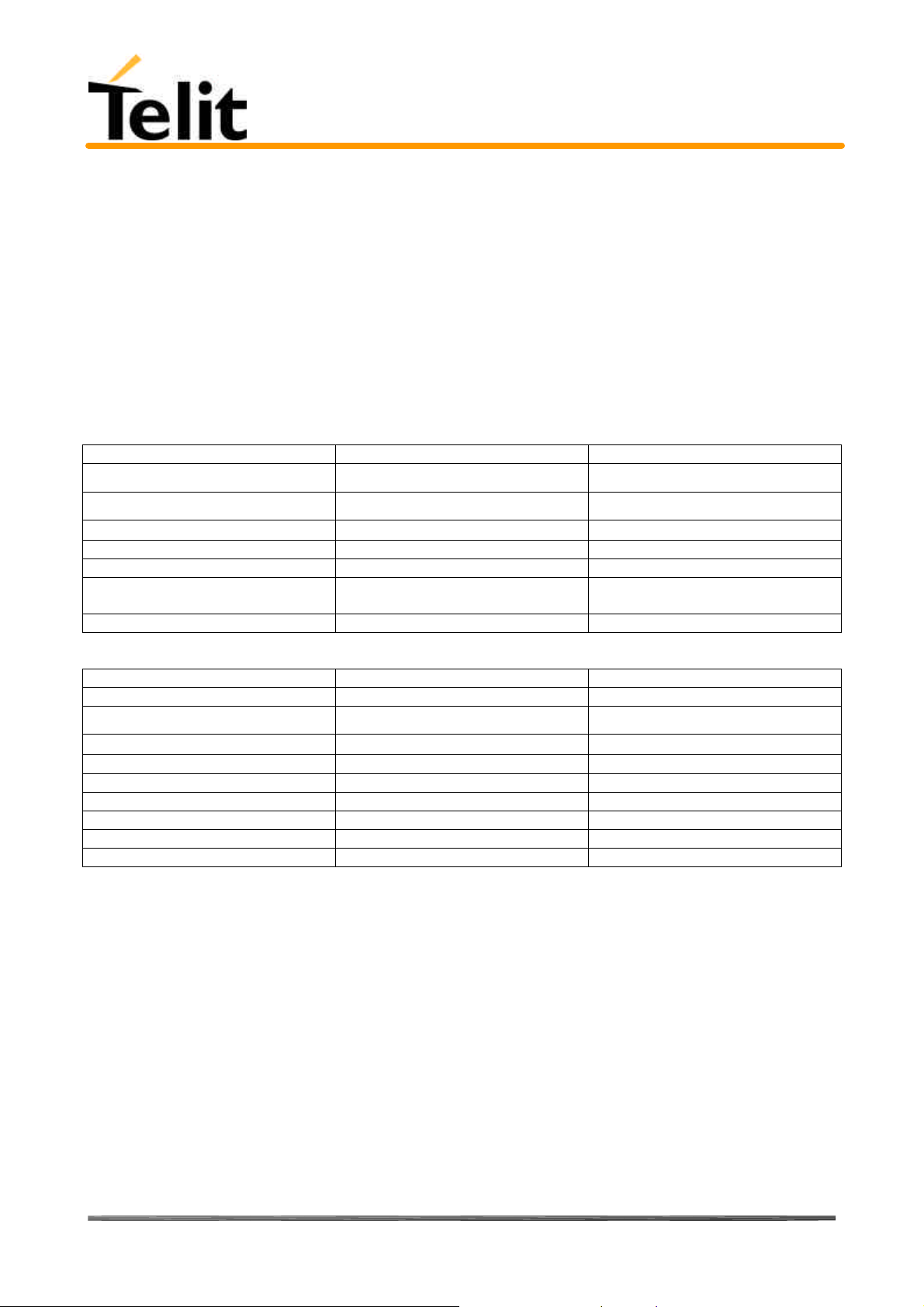
The following table reports all the audio level specifications.
Microphone characteristics
Internal audio mic. input External audio mic. input
Line coupling
Line type
Differential input resistance
Line nominal sensitivity 50mV
Max input voltage 360mV
Microphone nominal sensitivity -
Analog Gain suggested
Echo canceller type handset Car kit hands free
AC ( 100nF cond.) AC ( 100nF cond.)
Balanced Balanced
25kΩ 25kΩ
3mV
22mV
rms
rms
Vrms/Pa
/ +10dB
-45dB
rms
rms
/ +24dB -45dB
Vrms/Pa
Speaker characteristics
Internal audio ear. output External audio ear. output
Line coupling DC DC
Line type
Speaker impedance
Minimun load impedance
Bridged Bridged
≥ 16Ω ± 5% @ 1kHz ≥ 16Ω ± 5% @ 1kHz
15Ω 15Ω
Signal bandwidth 150-8000 Hz @ -3dB 150-8000 Hz @ -3dB
Maximum output 1700mV
rms
850mV
rms
Maximum power output 30mW 7.5mW
Volume level steps (SW) -2dB -2dB
Number of volume steps (SW) 10 10
Reproduction forbidden without DAI Telecom written authorization – All Right reserved – Right of modification reserved page 20 of 202
Page 21

Telit TRIZIUM Product Description
80264ST10007a Rev. 4– 09/09/04
2.16 Interfaces on TRIZIUM
TRIZIUM PIN-OUT
Pin Signal I/O Function Internal
Pull up
1 PD5
GPIO13
2 PD4
GPIO12
3 PD3
GPIO11
4 PD2
GPIO10
5 PD1
GPIO9
6 PD0
GPIO8
7 MON1_CAM I/O Camera clock (4) CMOS 2.8V
8 GND - Ground Power
9 EAR_MT- AO Handset earphone signal output, phase - Audio
10 EAR_MT+ AO Handset earphone signal output, phase + Audio
11 EAR_HF+ AO Handsfree ear output, phase + Audio
12 EAR_HF- AO Handsfree ear output, phase - Audio
13 MIC_MT+ AI Handset microphone signal input; phase+, nominal level
14 MIC_MT- AI Handset microphone signal input; phase-, nominal level
15 MIC_HF+ AI Handsfree microphone input; phase +, nominal level
16 MIC_HF- AI Handsfree microphone input; phase -, nominal level
17 GND - Ground Power
18 SIMCLK O External SIM signal – Clock 3V ONLY
19 SIMRST O External SIM signal – Reset 3V ONLY
20 SIMIO I/O External SIM signal - Data I/O 3V ONLY
21 CCIN I/O External SIM signal - Presence (active low)
22 SIMVCC - External SIM signal – Power (3) 3V ONLY
23 ADC AI Analog/Digital converter input A/D
24 VBATT - Main power supply Power
25 TX_TRACE TX Data for debug monitor (1) CMOS 2.8V
26 RX_TRACE RX Data for debug monitor (1) CMOS 2.8V
27 VRTC AO VRTC Backup capacitor Power
28 GND - Ground Power
29 STAT_LED O Status indicator led CMOS 2.8V
I/O Port D5 / GPIO13 (4) CMOS 2.8V
I/O Port D4 / GPIO12 (4) CMOS 2.8V
I/O Port D3 / GPIO11 (4) CMOS 2.8V
I/O Port D2 / GPIO10 (4) CMOS 2.8V
I/O Port D1 / GPIO9 (4) CMOS 2.8V
I/O Port D0 / GPIO8 (4) CMOS 2.8V
50mVrms
50mVrms
3mVrms
3mVrms
47KΩ
Type
Audio
Audio
Audio
Audio
CMOS 2.8V
Reproduction forbidden without DAI Telecom written authorization – All Right reserved – Right of modification reserved page 21 of 202
Page 22

Telit TRIZIUM Product Description
80264ST10007a Rev. 4– 09/09/04
30 AXE I Handsfree switching
31 VOUT - Power output for external accessories (camera) 32 IICSDA GPIO4 I/O Camera IIC interface / GPIO4 Configurable general
purpose I/O pin (4)
33 IICSCL GPIO2 I/O Camera IIC interface / GPIO2 Configurable general
purpose I/O pin (4)
34 GPIO1 I/O GPIO1 Configurable general purpose I/O pin CMOS 2.8V
35 CHARGE AI Charger input Power
36 GND - Ground Power
37 C103/TXD I Serial data input (TXD) from DTE CMOS 2.8V
38 C104/RXD O Serial data output to DTE CMOS 2.8V
39 C108/DTR I Input for Data terminal ready signal (DTR) from DTE (4) CMOS 2.8V
40 C105/RTS I Input for Request to send signal (RTS) from DTE CMOS 2.8V
41 C106/CTS O Output for Clear to send signal (CTS) to DTE CMOS 2.8V
42 C109/DCD O Output for Data carrier detect signal (DCD) to DTE CMOS 2.8V
43 C107/DSR O Output for Data set ready signal (DSR) to DTE CMOS 2.8V
44 C125/RING O Output for Ring indicator signal (RI) to DTE CMOS 2.8V
45 GND
46 ON/OFF I Input command for switching power ON or OFF (toggle
47 RESET I Reset input
48 GND - Ground Power
49 ANTENNA O Antenna output - 50 ohm RF
50 GND - Ground Power
51 OE_CAM
GPIO7
52 CAM_SYNC I/O Camera Sync (4) CMOS 2.8V
53 CAM_DRDY
GPIO5
54 PD7
GPIO6
55 PD6
GPIO3
56 GND - Ground Power
(1) For the exclusive use of the Technical Support Service
(2) An earphone with a 150 ohm impedance can be directly connected to EAR+ and EAR–
(3) On this pin a maximum of 47nF bypass capacitor is allowed.
(4) When activating the Easy camera these pins will not be available for other use
Ground Power
-
command). The pulse to be sent to the TRIZIUM must be
equal or greater than 1 second.
I/O Output Enable Camera / GPIO7 (4) CMOS 2.8V
I/O Camera DRDY / GPIO5 (4) CMOS 2.8V
I/O Port D7 / GPIO6 (4) CMOS 2.8V
I/O Port D6 / GPIO3 (4) CMOS 2.8V
100KΩ
47KΩ
2KΩ
CMOS 2.8V
CMOS 2.8V
CMOS 2.8V
Pull up to VBATT
see par.2.12.1
Reproduction forbidden without DAI Telecom written authorization – All Right reserved – Right of modification reserved page 22 of 202
Page 23
Telit TRIZIUM Product Description
80264ST10007a Rev. 4– 09/09/04
2.17 Mounting the TRIZIUM on your Board
2.17.1 General
Trizium module has been designed in order to be compliant with a standard smt process, with the
following details.
2.17.2 Module finishing & dimensions
All quotes are in mm, general tolerance ± 0.1
Surface finishing Ni/Au for all test pads
(in white on the drawing).
Surface finishing Sn63/Pb37 for all solder pads
(in black on the drawing).
Reproduction forbidden without DAI Telecom written authorization – All Right reserved – Right of modification reserved page 23 of 202
Page 24
Telit TRIZIUM Product Description
80264ST10007a Rev. 4– 09/09/04
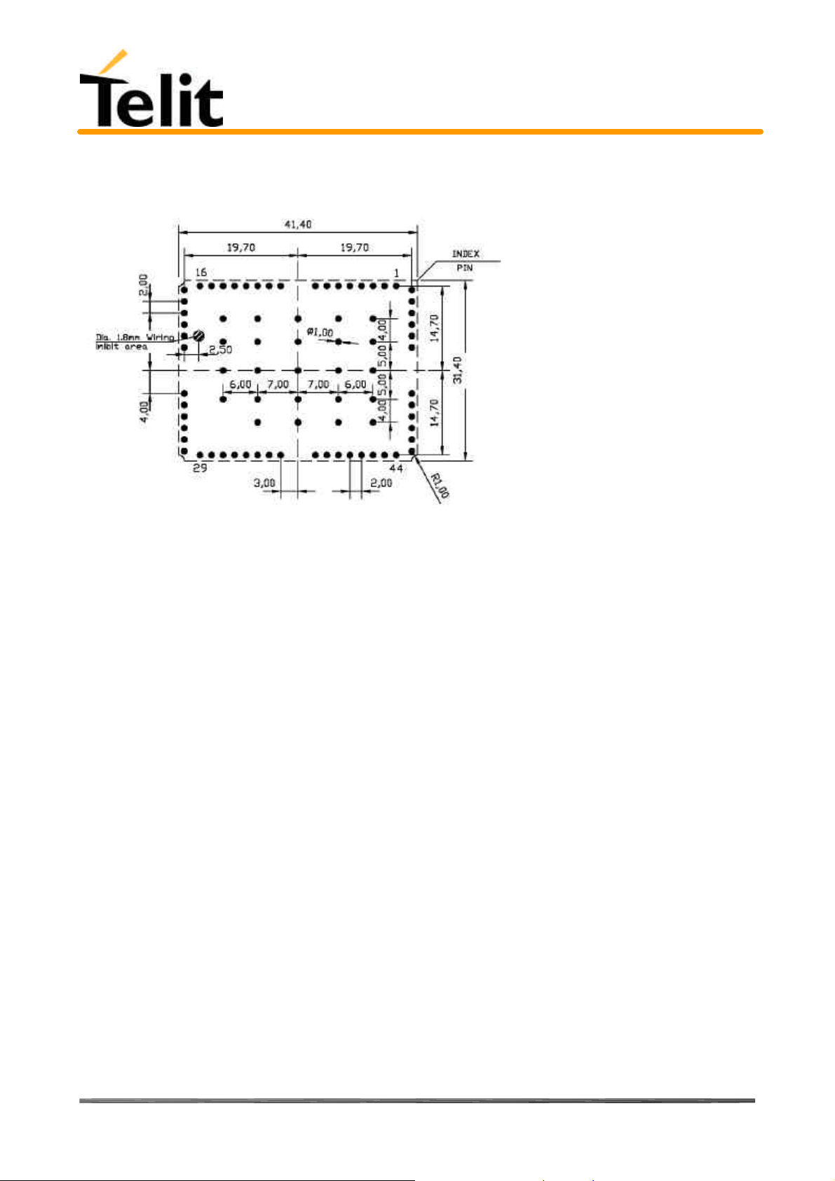
2.17.3 Recommended foot print for application
2.17.4 Stencil
Stencil’s apertures layout can be the same of the recommended footprint (1:1), we suggest a
thickness of stencil foil = 120µm.
Reproduction forbidden without DAI Telecom written authorization – All Right reserved – Right of modification reserved page 24 of 202
Page 25
Telit TRIZIUM Product Description
Temperature (ºC)
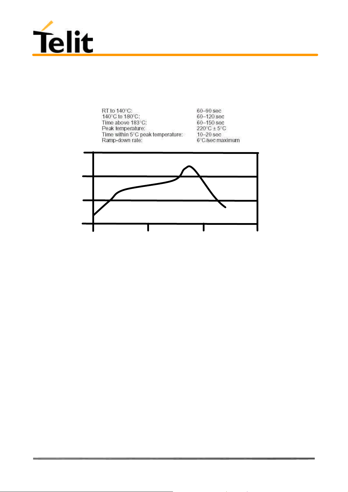
2.17.5 Solder reflow
The following is the recommended solder reflow profile
300
200
100
80264ST10007a Rev. 4– 09/09/04
0
0
100 200 300
Time (sec)
NOTE : This is an ideal profile, and actual conditions obtained in any specific reflow oven will
vary. This profile is based on convection or RF plus forced convection heating.
NOTICE: Trizium module can accept only one reflow process
Reproduction forbidden without DAI Telecom written authorization – All Right reserved – Right of modification reserved page 25 of 202
Page 26

Telit TRIZIUM Product Description
170 ± 0,3
6.1
80264ST10007a Rev. 4– 09/09/04
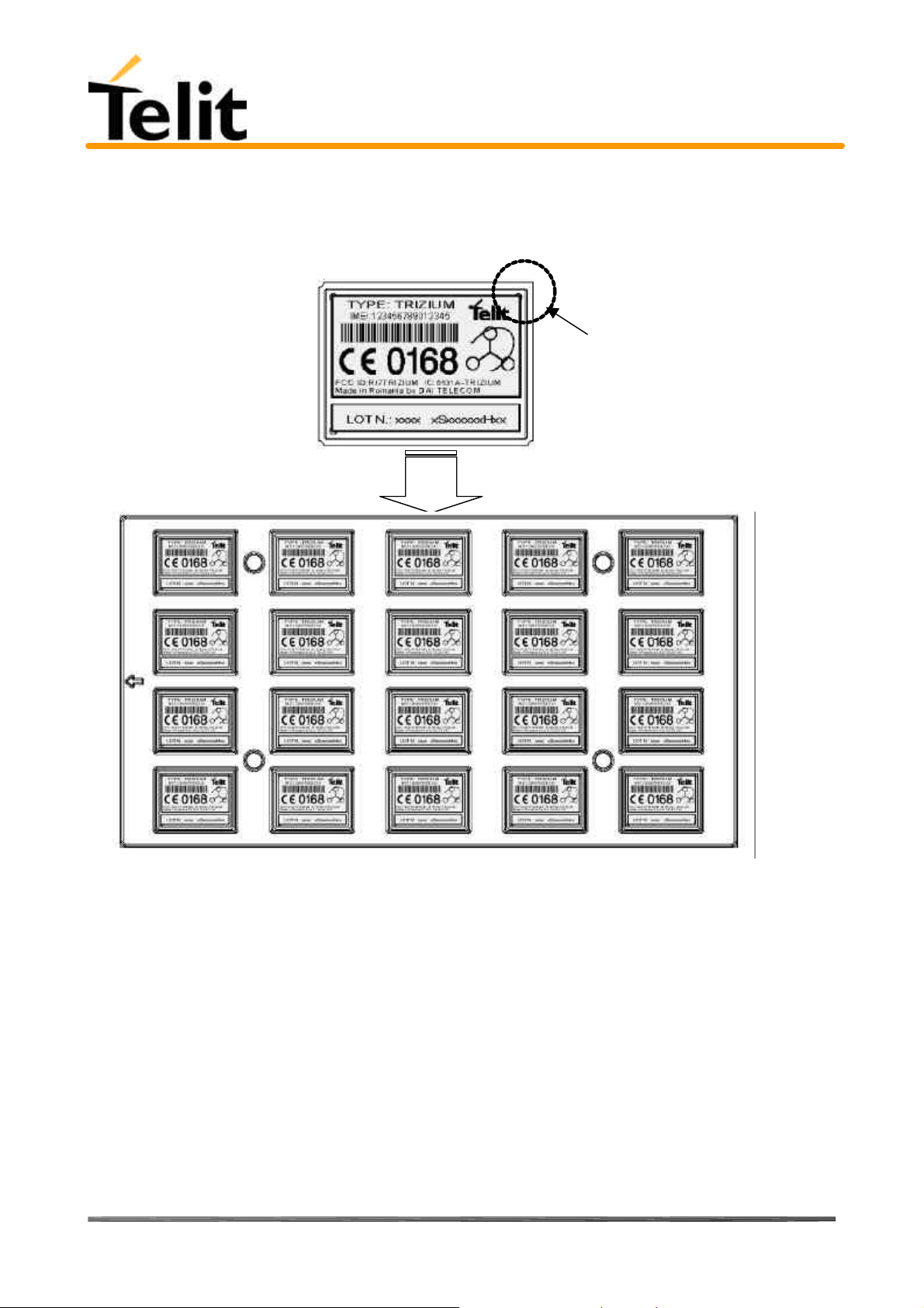
2.17.6 Packing system
According to smt processes for pick & place mouvement requirements, Trizium modules are
packaged on trays, each tray contains 20 pieces. Tray dimensions are::
Section A-A
All quotes are in mm, general tolerance ± 0.1
Reproduction forbidden without DAI Telecom written authorization – All Right reserved – Right of modification reserved page 26 of 202
Page 27
Telit TRIZIUM Product Description
Note that trays can withstand a maximum temperature of 65° C.
Modules orientation on tray:
80264ST10007a Rev. 4– 09/09/04
Ref. No rounded corner on
module’s printed circuit
board indicates pin 1 corner
Reproduction forbidden without DAI Telecom written authorization – All Right reserved – Right of modification reserved page 27 of 202
Page 28

Telit TRIZIUM Product Description
80264ST10007a Rev. 4– 09/09/04
2.17.7 Moisture sensibility
The level of moisture sensibility of Trizium module is “3”, in according with standard IPC/JEDEC J-STD-020, take
care all the relatives requirements for using this kind of components.
Reproduction forbidden without DAI Telecom written authorization – All Right reserved – Right of modification reserved page 28 of 202
Page 29
Telit TRIZIUM Product Description
80264ST10007a Rev. 4– 09/09/04
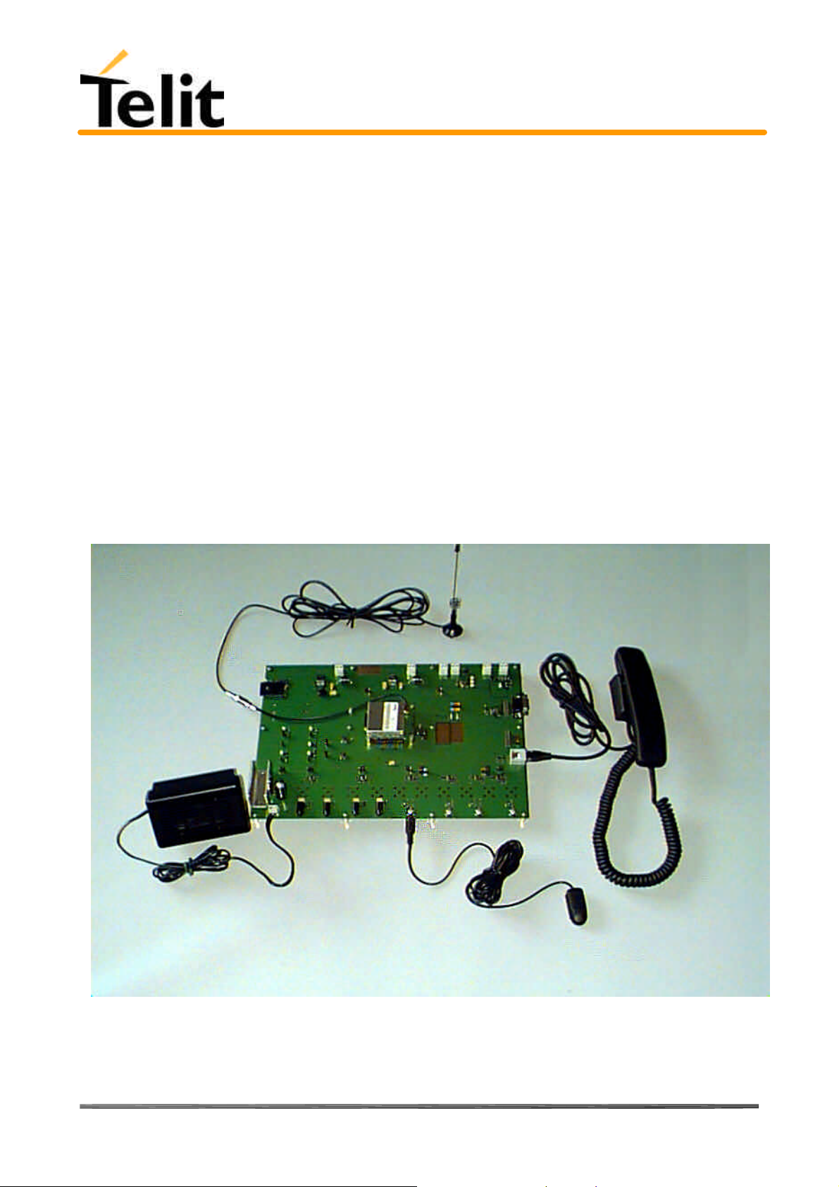
3 Evaluation Kit
In order to assist you in the development of your Telit TRIZIUM module based application, Telit can supply an Evaluation
Kit (same as used for the GM862 family, with a dedicated adaptor) with appropriate power supply, SIM card housing,
RS 232 serial port level translator, direct UART connection, Handset, Headset and Hands-free (car kit) audio, antenna.
The EVK provides a fully functional solution for a complete data/phone application.
The standard serial RS232 9 pin connector placed on the Evaluation Kit allows the connection of the
EVK system with a PC or other DTE.
The development of the applications utilizing the Telit TRIZIUM module must present a proper design
of all the interfaces towards and from the module (e.g. power supply, audio paths, level translators),
otherwise a decrease in the performances will be introduced or, in the worst case, a wrong design
can even lead to an operating failure of the module.
In order to assist the hardware designer in his project phase, the EVK board presents a series of
different solutions, which will cover the most common design requirements on the market, and
which can be easily integrated in the OEM design as building blocks or can be taken as starting
points to develop a specific one.
TRIZIUM Evaluation Kit (adaptor not shown)
Reproduction forbidden without DAI Telecom written authorization – All Right reserved – Right of modification reserved page 29 of 202
Page 30
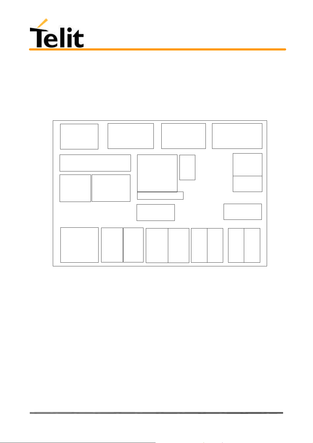
Telit TRIZIUM Product Description
ADAPTOR
ANTENNA COAX
AUDIO/BF
ANCE
D
ANCE
D
ENDED
80264ST10007a Rev. 4– 09/09/04
3.1 Evaluation Kit description
For a detailed description of the Telit Evaluation Kit refer to the documentation provided with the Telit TRIZIUM
Hardware User Guide.
The Telit Evaluation Kit can be divided into different blocks depending on the function they implement.
A schematic showing the EVK board and its blocks is shown:
SIM HOUSING
FREE SPACE
ON/OFF
GPIO & LEDS
HIGH POWER
EXT. EAR
& RESET
BUTTONS
BRIDGED
3.1.1 Power Supply
+12V
POWER SUPPLY
REGULATORS
EXT
EAR
EXT
EAR
SINGLE
ENDED
TRIZIUM
FILTERS
HANDSET
EAR
BRIDGED
+5V
POWER SUPPLY
REGULATORS
GPIO
EVK
HANDSET
EAR
SINGLE
EXT
MIC
BALAN
CED
BATTERY SUPPLY
& CHARGE CONTROL
TRANSLATOR
+3V UART
HANDSET
CONNECTOR
EXT
MIC
UNBAL
HAND
SET
MIC
BALAN
CED
RS232
LEVEL
HAND
SET
MIC
UNBAL
In the Board there are three different power sources, that embrace a wide range of applications, from the automotive
+12V input to the stand alone battery powered device.
The power sources nominal input voltages are:
• +12V input (typically automotive)
• +5V input (typically embedded systems)
• +3.8V input (Li-Ion Battery)
Each one of these power sources can supply both the Telit TRIZIUM module and the whole circuitry embodied in the
Evaluation Kit.
Only one of these power sources can be used at a time and it is selectable with two jumpers.
For the battery power supply a Li-Ion battery charger circuit is provided.
3.1.2 Serial interface
The communications between your application and the Telit TRIZIUM module must be done through a serial interface
which can be a standard CMOS UART or a RS232 port.
All levels of the RS232 port are conform to RS232 and V.24 standard and a PC serial port can be directly connected to
this connector.
Reproduction forbidden without DAI Telecom written authorization – All Right reserved – Right of modification reserved page 30 of 202
Page 31

Telit TRIZIUM Product Description
80264ST10007a Rev. 4– 09/09/04
Both these interfaces are supported.
3.1.3 Audio
The Evaluation Kit board provides two software/hardware selectable audio paths, the internal and the external one. All
the handset, headset and hands free-car kit functions are supported.
Furthermore for each audio path two solution are presented: single ended and balanced.
3.1.4 GPIO and Leds
All the General Purpose Input Output ports of the Telit TRIZIUM module are supported in a dedicated connector and
several leds are added as a debug aid.
Reproduction forbidden without DAI Telecom written authorization – All Right reserved – Right of modification reserved page 31 of 202
Page 32

Telit TRIZIUM Product Description
80264ST10007a Rev. 4– 09/09/04
4 Service and firmware update
The serial cable used for the communication with a PC can be also used to update the Telit TRIZIUM module firmware.
The RS232 connector DB type 9 pin 90° is used to connect the Telit Evaluation Kit. to any DTE .
All levels are conformed to RS232 and V.24 standard and a PC serial port can be directly connected to this connector.
The firmware update can be done with a specific software tool provided by Telit that runs on windows based PCs.
4.1 Step-by-Step upgrade procedure
I. Download the specific software for upgrading (Flash programmer TFI_TRIZIUM.zip).from the site
www.TRIZIUM.com, or request it at this e-mail address ts-trizium@telit.net
II. Unzip the file TFI_TRIZIUM.zip. A new folder TRIZIUM/ will be created
III. Mount the Telit TRIZIUM module in the Evaluation Kit (using the dedicated adaptor)and supply power
IV. Run the file TFI_TRIZIUM.exe.
V. Press the Start Procedure button and within 5 seconds press the ON/OFF button on the
board. Keep pressed the ON/OFF button for 5 seconds and then leave it.
First the program will erasure the content of flash memory
Then the program will write on the flash memory
Wait for the end of programming green message COK
Your Telit TRIZIUM module is now programmed with the new firmware.
Reproduction forbidden without DAI Telecom written authorization – All Right reserved – Right of modification reserved page 32 of 202
Page 33

Telit TRIZIUM Product Description
80264ST10007a Rev. 4– 09/09/04
5 AT Command
The Telit TRIZIUM module can be driven via the serial interface using the standard AT commands1. The Telit TRIZIUM
module is compliant with:
1. Hayes standard AT command set, in order to maintain the compatibility with existing SW programs.
2. ETSI GSM 07.07 specific AT command and GPRS specific commands.
3. ETSI GSM 07.05 specific AT commands for SMS (Short Message Service) and CBS (Cell Broadcast Service)
4. FAX Class 1 compatible commands
Moreover the Telit TRIZIUM module supports also Telit proprietary AT commands for special purposes.
In the following the dedicated description of how to use the AT commands with the Telit TRIZIUM module.
5.1 Definitions
The following syntactical definitions apply:
<CR> Carriage return character, is the command line and result code terminator character, which value, in decimal
ASCII between 0 and 255,is specified within parameter S3.
The default value is 13.
<LF> Linefeed character, is the character recognised as line feed character. Its value, in decimal ASCII between 0
and 255, is specified within parameter S4. The default value is 10.
The line feed character is output after carriage return character if verbose result codes are used (V1 option used )
otherwise, if numeric format result codes are used (V0 option used) it will not appear in the result codes.
<...> Name enclosed in angle brackets is a syntactical element. They do not appear in the command line.
[...] Optional subparameter of a command or an optional part of TA information response is enclosed in square
brackets. Brackets themselves do not appear in the command line. When subparameter is not given in AT commands
which have a read command, new value equals to its previous value. In AT commands which do not store the values of
any of their subparameters, and so have not a read command, which are called action type commands, action should be
done on the basis of the recommended default setting of the subparameter.
5.2 AT Command Syntax
GSM commands use syntax rules of extended commands.
Every extended command has a test command (trailing =?) to test the existence of the command and to give
information about the type of its subparameters. There are two types of extended command:
- Parameter type commands which also have a read command (trailing ?) to check the current values of
subparameters.
- Action type commands do not store the values of any of their possible subparameters, and therefore do not have a
read command.
5.2.1 Command lines
The basic structure of the command lines are:
• ATCMD1<CR> where AT is the command line prefix, CMD1 is a basic command (i.e. it have not + prefix) and
CR is the command line terminator character
• ATCMD2=10<CR> where 10 is a subparameter
• AT+CMD1;+CMD2=, ,10<CR> These are two examples of extended commands (which have a + prefix). They are
delimited with semicolon. In the second command the subparameter is omitted
• +CMD1?<CR> This is a read command for checking current subparameter values
1
The AT is an ATTENTION command and is used as a prefix to other parameters in a string. The AT command
combined with other parameters can be set up in the communications package or typed in manually as a command line
instruction.
Reproduction forbidden without DAI Telecom written authorization – All Right reserved – Right of modification reserved page 33 of 202
Page 34

Telit TRIZIUM Product Description
80264ST10007a Rev. 4– 09/09/04
• +CMD1=?<CR> This is a test command for checking possible subparameter values
These commands might be performed in a single command line as shown below:
ATCMD1 CMD2=10+CMD1;+CMD2=, ,10;+CMD1?;+CMD1=?<CR>
anyway it is always preferable to separate into different command lines the basic commands (i.e. without + prefix) and
the extended commands (the ones with + prefix); furthermore it is suggested to avoid placing several action commands
in the same command line, because if one of them fails, then an error message is received but it is not possible to argue
which one of them has failed the execution.
If command V1 is enabled (verbose responses codes) and all commands in a command line has been performed
successfully, result code <CR><LF>OK<CR><LF> is sent from the TA to the TE, if subparameter values of a
command are not accepted by the TA or command itself is invalid, or command cannot be performed for some reason,
result code <CR><LF>ERROR<CR><LF> is sent and no subsequent commands in the command line are processed.
If command V0 is enabled (numeric responses codes), and all commands in a command line has been performed
successfully, result code 0<CR> is sent from the TA to the TE, if sub-parameter values of a command are not accepted
by the TA or command itself is invalid, or command cannot be performed for some reason, result code 4<CR> and no
subsequent commands in the command line are processed.
In case of errors depending on ME operation, ERROR (or 4) response may be replaced by +CME ERROR: <err> or
+CMS ERROR: <err>.
Reproduction forbidden without DAI Telecom written authorization – All Right reserved – Right of modification reserved page 34 of 202
Page 35

Telit TRIZIUM Product Description
80264ST10007a Rev. 4– 09/09/04
5.2.2 Information responses and result codes
The TA response, in case of verbose response format enabled, for the previous examples command line could be as
shown below:
information response to +CMD1? <CR><LF>+CMD1:2,1,10<CR><LF>
information response to +CMD1=? <CR><LF>+CMD1(0-2),(0,1),(0-15)<CR><LF>
final result code <CR><LF>OK<CR><LF>
Moreover there are other two types of result codes:
• result codes that inform about progress of TA operation (e.g. connection establishment CONNECT)
• result codes that indicate occurrence of an event not directly associated with issuance of a command from TE (e.g.
ring indication RING).
Here the basic result codes according to ITU-T V25Ter recommendation
Result Codes
Numeric form Verbose form
0 OK
1 CONNECT
2 RING
3 NO CARRIER
4 ERROR
6 NO DIALTONE
7 BUSY
8 NO ANSWER
5.2.3 Command Response Timeout
Every command issued to the Telit TRIZIUM module returns a result response if response codes are enabled (default). The
time needed to process the given command and return the response varies from command to command and may depend
also from the network on which the command may interact. As a result every command is provided with a proper
timeout time, if this time elapses without any result from the operation, then an ERROR response can be reported as if
the operation was not successful and the operation is anyway terminated.
The timeout time is quite short for commands that imply only internal set up commands, but may be very long for
command that interact with the network (or even a set of Networks).
The default timeout is 100 ms for all the commands that have no interaction with the network or upper software layers.
In the table below are listed all the commands whose timeout differs from the default 100 ms and their effective timeout
is reported:
Command Timeout (Seconds)
+CBST 0.2
+CR 0.2
+CRC 0.2
+CRLP 0.2
+CSCS 0.2
+CEER 5
+CGMI 5
+CGMM 5
+CGMR 5
+CGSN 20
+CIMI 20
+CNUM 20
+CREG 5
+COPS 180
Reproduction forbidden without DAI Telecom written authorization – All Right reserved – Right of modification reserved page 35 of 202
Page 36

Telit TRIZIUM Product Description
80264ST10007a Rev. 4– 09/09/04
+CLCK 180
+CPWD 180
+CLIP 180
+CLIR 180
+CCFC 180
+CCWA 20
+CHLD 20
+CUSD 180
+CAOC 20
+CSSN 20
+CLCC 20
+CPAS 5
+CPIN 20
+CSQ 5
+CPBS 5
+CPBR 20
+CPBF 20
+CPBW 20
+CALM 5
+CRSL 5
+CLVL 5
+CMUT 5
+CACM 20
+CAMM 20
+CPUC 20
+CMEE 5
+VTS 20
+GMI 5
+GMM 5
+GMR 5
+GSN 20
I3 5
I4 5
I5 5
+CSMS 5
+CPMS 5
+CMGF 5
+CSCA 20
+CSMP 5
+CSDH 5
+CSAS 5
+CRES 5
+CNMI 5
+CMGS 180 / 5 for prompt">"
+CMSS 180
+CMGW 5 / 5 for prompt">"
+CMGD 5
+CMGR 5
+CMGL 5
#CAP 10
Reproduction forbidden without DAI Telecom written authorization – All Right reserved – Right of modification reserved page 36 of 202
Page 37

Telit TRIZIUM Product Description
80264ST10007a Rev. 4– 09/09/04
#SRS 10
#SRP 10
#STM 10
#PCT 10
#SHDN 10
#QTEMP 10
#SGPO 10
#GGPI 10
#MONI 10
+CGACT 180
+CGATT 180
+CGDATA 20
+CGDCONT 20
+CGPADDR 20
+CGQMIN 20
+CGQREQ 20
5.2.4 Command issuing timing
The chain Command -> Response shall always be respected and a new command must not be issued before the
TRIZIUM has terminated all the sending of its response result code (whatever it may be).
This applies especially to applications that "sense" the OK text and therefore may send the next command before the
complete code <CR><LF>OK<CR><LF> is sent by the TRIZIUM.
It is advisable anyway to wait for at least 20ms between the end of the reception of the response and the issue of the
next AT command.
If the response codes are disabled and therefore the module does not report any response to the command, then at least
the 20ms pause time shall be respected.
During command mode, due to hardware limitations, under severe CPU load the serial port can loose some characters if
placed in autobauding at high speeds. Therefore if you encounter this problem fix the baud rate with AT+IPR
command.
5.2.5 Factory Profile and parameters stored in the profile
The TRIZIUM stores several command configurations in the internal non volatile memory (see command &W),
allowing to remember this status even after power off.
The parameters that are stored in the profile and their are:
GSM DATA MODE : +CBST: 0,0,1
AUTOBAUD : +IPR: 0
COMMAND ECHO : E1
RESULT MESSAGES : Q1
VERBOSE MESSAGES : V1
EXTENDED MESSAGES : X1
FLOW CONTROL OPTIONS : &K3
CTS (C106) OPTIONS : &B2
DSR (C107) OPTIONS : &S3
DTR (C108) OPTIONS : &D0
DCD (C109) OPTIONS : &C1
RI (C125) OPTIONS : \R1
C108/1 OPERATION : &D4
POWER SAVING : +CFUN: 1
DEFAULT PROFILE : &Y0
S REGISTERS: S0=0;S1=0;S2=43;S3=13;S4=10;S5=8;S7=60;S12=50;S25=5;S38=20
Reproduction forbidden without DAI Telecom written authorization – All Right reserved – Right of modification reserved page 37 of 202
Page 38

Telit TRIZIUM Product Description
80264ST10007a Rev. 4– 09/09/04
5.3 Hayes Compliant AT Commands
5.3.1 Generic Modem Control
5.3.1.1 &F - restore factory configuration
&F – restore factory configuration
Execute command
AT&F
Read command
Write command
Test command
Example
Reference V25ter.
SW release Version A
Calls the factory configuration, resetting the default profile.
5.3.1.2 Z - soft reset
Z – soft reset
Execute command
ATZ <n>
Read command
Write command
Test command
Example
Reference V25ter.
SW release Version A
Send a software reset to device, loading on the configuration the specified default profile.
Parameter: <n > = 0…1 - profile
Note: Must be the last command on the line.
Reproduction forbidden without DAI Telecom written authorization – All Right reserved – Right of modification reserved page 38 of 202
Page 39

Telit TRIZIUM Product Description
5.3.1.3 +FCLASS - select active service class
+FCLASS - select active service class
Execute command
Read command
AT+FCLASS?
Write command
AT+FCLASS= <n>
Test command
AT+FCLASS=?
Example
Reference GSM 07.07
SW release Version A
Returns the current configuration value of the parameter <n>.
Set the TRIZIUM in specified connection mode (data, fax, voice), hence all the calls done
after, will be data or voice.
Parameter:
<n>: 0 = data
<n>: 1 = fax class 1
<n>: 8 = voice
Returns all supported values of the parameters <n>.
80264ST10007a Rev. 4– 09/09/04
5.3.1.4 &Y - designate a default reset profile
&Y – designate a default reset profile
Execute command
AT&Y <n>
Read command
Write command
Test command
Example
Reference
SW release Version A
The TRIZIUM is able to store 2 complete configurations (see command &W). The
command &Y defines which one of the 2 profiles will be the default profile to be loaded on
startup.
Parameter: <n> = 0…1 - profile
Note: Differently from ATZ<n> command which simply loads the desired profile , with the
command AT&Y the chosen profile becomes the one which will be loaded on every startup.
5.3.1.5 &W - store current configuration
&W – store current configuration
Execute command
AT&W <n>
Read command
Write command
Test command
Example
Reference
SW release Version A
Stores on profile n the complete configuration of the device.
Parameter: <n> = 0…1 - profile
Reproduction forbidden without DAI Telecom written authorization – All Right reserved – Right of modification reserved page 39 of 202
Page 40

Telit TRIZIUM Product Description
80264ST10007a Rev. 4– 09/09/04
5.3.1.6 &Z - store telephone number in the Telit TRIZIUM module internal
phonebook
&Z – store telephone number in the TRIZIUM internal phonebook
Execute command
AT&Z <n> = <nr>
Read command
Write command
Test command
Example
Reference
SW release Version A
The TRIZIUM has a built in non volatile memory in which telephone numbers of a
maximum 24 digits can be stored. The command AT&Z <n> = <nr> stores in the record n
the telephone number nr. The records cannot be overwritten, they must be cleared before
rewriting.
Parameter:
<n>: phonebook record <nr>: telephone number
Note1: To delete the record <n> the command AT&Z<n>= must be issued.
Note2: The records in the TRIZIUM memory can be viewed with the
command AT&N, while the telephone number stored in the record n can be
dialled by giving the command ATDS=<n>.
Reproduction forbidden without DAI Telecom written authorization – All Right reserved – Right of modification reserved page 40 of 202
Page 41

Telit TRIZIUM Product Description
80264ST10007a Rev. 4– 09/09/04
5.3.1.7 &N - display internal phonebook stored numbers
&N – display internal phonebook stored numbers
Execute command
AT&N <n>
Read command
Write command
Test command
Example
Reference
SW release Version A
5.3.1.8 +GMI - request manufacturer identification
+GMI – request manufacturer identification
Execute command
AT+GMI
Read command
Write command
Test command
Example
Reference V.25ter
SW release Version A
Returns the telephone number stored in the internal memory at the record number <n>.
Parameter: <n> - phonebook record
Note: if parameter <n> is omitted then all the internal records are shown.
Returns the manufacturer identification.
5.3.1.9 +GMM - request model identification
+GMM – request model identification
Execute command
AT+GMM
Read command
Write command
Test command
Example
Reference V.25ter
SW release Version A
Returns the model identification.
5.3.1.10 +GMR - request revision identification
+GMR – request revision identification
Execute command
AT+GMR
Read command
Write command
Test command
Example
Reference V.25ter
SW release Version A
Returns the software revision identification.
5.3.1.11 +GCAP - request capabilities list
+GCAP – request capabilities list
Execute command
AT+GCAP
Returns the equipment supported command set list.
Reproduction forbidden without DAI Telecom written authorization – All Right reserved – Right of modification reserved page 41 of 202
Page 42

Telit TRIZIUM Product Description
Read command
Write command
Test command
Example
Reference V.25ter
SW release Version A
5.3.1.12 +GSN - request serial number
+GSN – request serial number
Execute command
AT+GSN
Read command
Write command
Test command
Example
Reference V.25ter
SW release Version A
Returns the device board serial number.
Note: The number returned is not the IMSI, it is only the board number
80264ST10007a Rev. 4– 09/09/04
Reproduction forbidden without DAI Telecom written authorization – All Right reserved – Right of modification reserved page 42 of 202
Page 43

Telit TRIZIUM Product Description
80264ST10007a Rev. 4– 09/09/04
5.3.1.13 &V - display current configuration & profile
&V – display current configuration & profile
Execute command
AT&V
Read command
Write command
Test command
Example AT&V
Reference V25ter
SW release Version A
Returns all the configuration parameters settings.
DTE SPEED : 19200
DTE FORMAT : 8N1
CELLULAR PHONE : GSM TELIT: Operative
GSM DATA MODE : \N4=Not Trasparent
AUTOBAUD : +IPR0=YES
COMMAND ECHO : E1=YES
RESULT MESSAGES : Q0=YES
VERBOSE MESSAGES : V1=YES
EXTENDED MESSAGES : X1=YES
ECM TYPE MESSAGES : \V0=NO
LINE SPEED : F8=9600
CONSTANT DTE SPEED : \J0=YES
FLOW CONTROL OPTIONS : &K3=HW bidirect.
ERROR CORRECTION MODE : \N4=RLP
CTS (C106) OPTIONS : &B2=OFF while disc.
DSR (C107) OPTIONS : &S3=PHONE ready->ON
DTR (C108) OPTIONS : &D0=ignored
DCD (C109) OPTIONS : &C1=follows carrier
RI (C125) OPTIONS : \R1=OFF dur. off-hk
C108/1 OPERATION : &D4=NO
POWER SAVING ON DTR : +CFUN:1=NO
CALL ABORT : YES
DEFAULT PROFILE : &Y0=user profile 1
OK
5.3.1.14 &V0 - display current configuration & profile
&V0 – display current configuration & profile
Execute command
AT&V0
Read command
Write command
Test command
Example
Reference
SW release Version A
Returns all the configuration parameters settings.
Note: this command is the same as &V, it is included only for backwards
compatibility.
5.3.1.15 &V1 - display S registers values
&V1 – display S registers values
Execute command
AT&V1
Reproduction forbidden without DAI Telecom written authorization – All Right reserved – Right of modification reserved page 43 of 202
Returns the value of the S registers in decimal and hexadecimal value in the format:
Page 44

REG DEC HEX
<reg> <dec> <hex>
where
<reg> - S register number (0 .. 52)
<dec> - current value in decimal notation
<hex> - current value in hexadecimal notation
Read command
Write command
Test command
Example
Reference
SW release Version A
Telit TRIZIUM Product Description
80264ST10007a Rev. 4– 09/09/04
Reproduction forbidden without DAI Telecom written authorization – All Right reserved – Right of modification reserved page 44 of 202
Page 45

Telit TRIZIUM Product Description
5.3.1.16 &V2 - display last connection statistics
&V2 – display last connection statistics
Execute command
AT&V2
Read command
Write command
Test command
Example
Reference
SW release Version A
5.3.1.17 \V - single line connect message
\V – Single line connect message
Execute command
AT\V <n>
Read command
Write command
Test command
Example
Reference
SW release Version A
Returns the last connection statistics & connection failure reason.
Set single line connect message.
Parameter:
<n> = 0 - off
<n> = 1 on
80264ST10007a Rev. 4– 09/09/04
Reproduction forbidden without DAI Telecom written authorization – All Right reserved – Right of modification reserved page 45 of 202
Page 46

Telit TRIZIUM Product Description
5.3.1.18 %L - report line signal level
%L – report line signal level
Execute command
AT%L
Read command
Write command
Test command
Example
Reference
SW release Version A
5.3.1.19 %Q - report line quality
%Q – report line quality
Execute command
AT%Q
Read command
Write command
Test command
Example
Reference
SW release Version A
Reports the line signal level.
Note: Since on mobile phone there's no line connection, command is included only for
compatibility and returns only OK.
To check signal strength (level) use the +CSQ command.
Reports the line quality indicator.
Note: Since on mobile phone there's no line connection, command is included only for
compatibility and returns only OK.
To check signal quality use the +CSQ command.
80264ST10007a Rev. 4– 09/09/04
Reproduction forbidden without DAI Telecom written authorization – All Right reserved – Right of modification reserved page 46 of 202
Page 47

Telit TRIZIUM Product Description
5.3.2 DTE - modem interface control
5.3.2.1 E - command echo
E – command echo
Execute command
Read command
Write command
ATE <n>
Test command
Example
Reference V25ter
SW release Version A
Controls the command echo response of the device, enabling or disabling the echo.
Parameter:
<n> = 0 - disables command echo, hence after this command the only characters received
by DTE are the responses to commands sent to device.
<n> = 1 - enables command echo (default) , hence command sent to the device are echoed
back to the DTE before the response is given.
80264ST10007a Rev. 4– 09/09/04
5.3.2.2 Q - quiet resut codes
Q – quiet result codes
Execute command
Read command
Write command
ATQ <n>
Test command
Example
Reference V25ter
SW release Version A
Enables or disables the result codes.
Parameter:
<n> = 0 - enables result codes
<n> = 1 - disables result codes
Note: After disabling result codes with ATQ1, the device does not return a response to
commands (usually OK), but command are executed anyway.
Reproduction forbidden without DAI Telecom written authorization – All Right reserved – Right of modification reserved page 47 of 202
Page 48

Telit TRIZIUM Product Description
80264ST10007a Rev. 4– 09/09/04
5.3.2.3 V- result code form
V – result code form
Execute command
Read command
Write command
ATV <n>
Test command
Example
Reference V25ter
SW release Version A
5.3.2.4 X - extended result codes
X – extended result codes
Execute command
Read command
Write command
ATX <n>
Test command
Note For complete control on CONNECT response message see also +DR command.
Reference V25ter
SW release Version A
Sets the result code format.
Parameter:
<n> = 0 set the short format (terse) return codes are numbers 0-9.
<n> = 1 set the long form (verbose) return codes.
Note: Line feed is not issued before a short format result code.
Selects the result code messages subset used by the modem to inform the DTE of the result
of the commands.
Parameter:
<n> = 0 - send only OK, CONNECT, RING, NO CARRIER, ERROR, NO ANSWER
results. Busy tones reporting is disabled.
<n> = 1,2,3,4 - reports all messages (default).
Reproduction forbidden without DAI Telecom written authorization – All Right reserved – Right of modification reserved page 48 of 202
Page 49

Telit TRIZIUM Product Description
5.3.2.5 I - Request identifier and software checksum
I – request identifier and software checksum
Execute command
Read command
Write command
ATI <n>
Test command
Example
Reference V25ter
SW release
Returns the identifier and a software checksum.
Parameter:
<n> = 0 numerical identifier.
<n> = 1 TRIZIUM checksum
<n> = 2 checksum check result
<n> = 3 manufacturer, software product code
<n> = 4 product name
<n> = 5 DOB version
Version A
80264ST10007a Rev. 4– 09/09/04
5.3.2.6 &C - data carrier detect (DCD) control
&C – Data carrier detect (DCD) control
Execute command
Read command
Write command
AT&C <n>
Test command
Example
Reference V25ter
SW release Version A
Controls the RS232 DCD output behaviour.
Parameter:
<n> = 0 DCD remains high always.
<n> = 1 DCD follows the Carrier detect status: if carrier is detected DCD is high,
otherwise DCD is low. (default)
Reproduction forbidden without DAI Telecom written authorization – All Right reserved – Right of modification reserved page 49 of 202
Page 50

Telit TRIZIUM Product Description
5.3.2.7 &D - data terminal ready (DTR) control
&D – data terminal ready (DTR) control
Execute command
Read command
Write command
AT&D <n>
Test command
Example
Reference V25ter
SW release Version A
Controls the TRIZIUM behaviour to the RS232 DTR transitions.
Parameter:
<n> = 0 DTR transitions are ignored.
<n> = 1 when the TRIZIUM is connected, the high to low transition of DTR pin sets the
device in command mode, the current connection is NOT closed.
<n> = 2 when the TRIZIUM is connected , the high to low transition of DTR pin sets the
device in command mode and the current connection is closed.
Note: if AT&D2 command is issued, the device does not answer to incoming calls if DTR is
low, even if ATA command is given.
80264ST10007a Rev. 4– 09/09/04
5.3.2.8 &K - flow control
&K – flow control
Execute command
Read command
Write command
AT&K <n>
Test command
Example
Reference
SW release Version A
Controls the RS232 flow control behaviour.
Parameter.
<n> = 0 - disabled
<n> = 1 - only CTS active, Hardware mono-directional
<n> = 2 - XON/XOFF software mono direction
<n> = 3 - RTS/CTS active, Hardware bi-directional (default)
<n> = 4 - XON/XOFF, Software bi-directional with filtering
<n> = 5 - XON/XOFF, Software bi-directional without filtering (Pass Through)
<n> = 6 - RTS/CTS active, Hardware bi-directional & software XON/XOFF (bidirectional) with filtering
5.3.2.9 &S - data set ready (DSR) control
&S – data set ready (DSR) control
Execute command
Read command
Write command
AT&S <n>
Test command
Reproduction forbidden without DAI Telecom written authorization – All Right reserved – Right of modification reserved page 50 of 202
Controls the RS232 DSR pin behaviour:
n = 0 - always ON
n = 1 - follows the GSM traffic channel indication.
n = 2 - ON when connected
n = 3 - ON when device is ready to receive commands
Note: if option 1 is selected then DSR is tied up when the device receives from the network
the GSM traffic channel indication.
Page 51

Example
Reference V25ter
SW release Version A
Telit TRIZIUM Product Description
80264ST10007a Rev. 4– 09/09/04
Reproduction forbidden without DAI Telecom written authorization – All Right reserved – Right of modification reserved page 51 of 202
Page 52

Telit TRIZIUM Product Description
5.3.2.10 \R - ring (RI) control
\R – ring (RI) control
Execute command
Read command
Write command
AT\R <n>
Test command
Example
Reference
SW release Version A
5.3.2.11 +IPR - fixed DTE interface rate
+IPR – fixed DTE interface rate
Execute command
controls the RING output pin behaviour.
Parameter:
<n> = 0 - RING on during ringing and further connection
<n> = 1 – RING on during ringing
<n> = 2 - RING follows the ring signal
Note: to check the ring option status use the &V command.
80264ST10007a Rev. 4– 09/09/04
Read command
AT+IPR?
Write command
AT+IPR = <rate>
Test command
AT+IPR=?
Example
Reference V25ter
SW release Version A
Returns the current value of +IPR parameter.
Specifies the DTE speed at which the device accepts commands during command
mode operation, it may be used to fix the DTE-DCE interface speed.
Parameter:
<rate> = 0/300/1200/2400/4800/9600/19200/38400/57600/115200
If <rate> is unspecified or set to 0, then automatic speed detection is enabled and also
character format (see +ICF) is set to auto-detect.
If <rate> is specified and not 0, DTE-DCE speed is fixed at that speed, hence no
speed auto-detection (autobauding) is enabled.
Returns the supported serial port speed list.
5.3.2.12 +IFC - DTE - DTA flow control
+IFC – DTE-DTA flow control
Execute command
Read command
AT+IFC?
Write command
AT+IFC = <by_te>, <by_ta>
Returns active flow control settings.
Response
Selects the flow control behavior of the serial port in both directions: from DTE
to DTA (<by_ta> option) and from DTA to DTE (<by_te>)
Parameter:
<by_te> - flow control option for the data received by DTE,
<by_ta> - flow control option for the data sent by DTA
<by_te> = 0 - flow control None
<by_te> = 1 - XON/XOFF filtered
Reproduction forbidden without DAI Telecom written authorization – All Right reserved – Right of modification reserved page 52 of 202
Page 53

<by_te> = 2 - C105 (RTS)
<by_te> = 3 - XON/XOFF not filtered
<by_ta> = 0 - flow control None
<by_ta> = 1 - XON/XOFF
<by_ta> = 2 - C106 (CTS)
Note: This command is equivalent to &K command.
Test command
AT+IFC=?
Example
Reference V25ter
SW release Version A
Response
Returns all supported values of the parameters <by_te> and <by_ta>.
Telit TRIZIUM Product Description
80264ST10007a Rev. 4– 09/09/04
Reproduction forbidden without DAI Telecom written authorization – All Right reserved – Right of modification reserved page 53 of 202
Page 54

Telit TRIZIUM Product Description
5.3.2.13 +ILRR - DTE - modem rate reporting
+ILRR – DTE-modem rate reporting
Execute command
Read command
AT+ILRR?
Write command
AT+ILRR = <n>
Test command
AT+ILRR=?
Example
Reference V25ter
SW release Version A
Returns active setting of port speed rate reporting information.
Controls whether or not the +ILRR:<rate> information text is transmitted from
the TRIZIUM to the DTE.
Parameter:
<n> = 0 - local port speed rate reporting disabled
<n> = 1 - local port speed rate reporting enabled
Note: this information if enabled is sent upon connection.
Returns all supported values of the parameter <n>
80264ST10007a Rev. 4– 09/09/04
Reproduction forbidden without DAI Telecom written authorization – All Right reserved – Right of modification reserved page 54 of 202
Page 55

Telit TRIZIUM Product Description
5.3.2.14 +ICF - DTE - modem character format
+ICF – DTE-modem character format
Execute command
Read command
AT+ICF?
Write command
AT+ICF = <format>[,<parity>]
Test command
AT+ICF=?
Example
Reference V25ter
SW release Version A
Returns current value of the character format.
Defines the asynchronous character format to be used when autobauding is
disabled.
Parameter:
<format> = 0..5, < parity> = 0/1
AT+ICF = 0 - auto detect
AT+ICF = 1 - 8N2
AT+ICF = 2,0 - 8O1
AT+ICF = 2,1 - 8E1
AT+ICF = 3 - 8N1
AT+ICF = 5,0 - 7O1
AT+ICF = 5,1 - 7E1
Note: the character format is defined as: number of bit per char, parity bit
and stop bit; where parity can be None, Odd and Even. E.g. 8E1 means 8 bit
per char with the even parity bit and 1 stop bit.
Returns all supported values of the parameters <format> and <parity>
80264ST10007a Rev. 4– 09/09/04
Reproduction forbidden without DAI Telecom written authorization – All Right reserved – Right of modification reserved page 55 of 202
Page 56

5.3.3 Call Control
5.3.3.1 D - dial
D – dial
Execute command
ATD <number>
ATD <number> ;
ATD <n> [;]
ATD> <n> [;]
ATDL
ATDS=<nr>
ATD<n> I [;]
Starts a call to the phone number given as parameter.
Parameter: <number> - phone number to be dialled
Note: The call is a data call or voice call depending on +FCLASS setting. If AT+FCLASS=8
command was issued before calling then the call will be done as a voice call, instead if
AT+FCLASS=0 command was issued the call will be a data one. The default value of
+FCLASS is 0 hence calls are by default data ones.
The numbers accepted are 0-9 and *,#,”A”, ”B”, ”C”, ”D”,”+”.
For backwards compatibility with landline modems modifiers “T”, ”P”, ”R”, ”,”, ”W”, “!”,
“@” are accepted but have no effect.
Issues a VOICE call to the number given regardless of the current value of the parameter
+FCLASS, which remains unaffected.
Parameter: <number> - phone number to be dialled.
Issues a call (VOICE if ";" modifier is added to the end of the command) to the number
stored in the TRIZIUM internal phonebook position number <n>.
Parameter: <n> - internal phonebook position to be called
Issues a call (VOICE if ";" modifier is added to the end of the command) to the number
stored in the SIM phonebook in the record number <n>.
Parameter: <n> - SIM phonebook position to be called
Issues a call to the last number dialled.
Issues a call to the internally stored number at the position <nr>. ( See
commands &N and &Z)
Issues a call [voice if ; is added] overwriting the CLIR setting in order to hide the CLI to the
called party for the current call only.
Telit TRIZIUM Product Description
80264ST10007a Rev. 4– 09/09/04
ATD<n> i [;]
ATD<n> G[;]
ATD<n>g[;]
ATD*<gprs_sc>[*<ad
dr>]
[*[<L2P>][*[<cid>]]]]
#
Issues a call [voice if ; is added] overwriting the CLIR setting in order to show
the CLI to the called party for the current call only.
Issues a call [voice if ; is added] checking the CUG supplementary service for
the current call. Refer to +CCUG command.
This command is specific of GPRS functionality and causes the MT to
perform whatever actions are necessary to establish communication between
the TE and the external PDN.
Parameters:
<GPRS_SC> - (GPRS Service Code) a digit string (value 99) which identifies
a request to use the GPRS
<addr> - string that identifies the called party in the address space applicable
to the PDP.
<L2P>: a string which indicates the layer 2 protocol to be used (see
+CGDATA command). For communications software that does not support
arbitrary characters in the dial string, the following numeric equivalents shall
be used:
1 - PPP
Reproduction forbidden without DAI Telecom written authorization – All Right reserved – Right of modification reserved page 56 of 202
Page 57

D – dial
Other values are reserved and will result in an ERROR response to the set
command.
<cid>: a digit string which specifies a particular PDP context definition (see
+CGDCONT command).
Read command
Write command
Test command
Example
Reference V25ter.
SW release
Version A
Telit TRIZIUM Product Description
80264ST10007a Rev. 4– 09/09/04
Reproduction forbidden without DAI Telecom written authorization – All Right reserved – Right of modification reserved page 57 of 202
Page 58

5.3.3.2 T - set tone dial
T – set tone dial
Execute command
ATT
Read command
Write command
Test command
Example
Reference V25ter.
SW release Version A
It has no effect is included only for backward compatibility with landline modems.
5.3.3.3 P - set pulse dial
P – set pulse dial
Execute command
ATP
Read command
Write command
Test command
It has no effect is included only for backward compatibility with landline modems.
Telit TRIZIUM Product Description
80264ST10007a Rev. 4– 09/09/04
Example
Reference V25ter.
SW release Version A
5.3.3.4 A - answer
A – answer
Execute command
ATA
Read command
Write command
Test command
Example
Reference V25ter.
SW release Version A
It is used to answer to an incoming call if automatic answer is disabled.
Note: This command MUST be the last in the command line and must be followed
immediately by a <CR> character.
5.3.3.5 A/ - Last command automatic repetition
A/ – last command automatic repetition
Execute command
A/
Read command
Write command
Test command
It is used to execute again the last received command.
This command works only at fixed IPR.
Note: This command has been substituted with AT#/ command.
Refer to #/ command reference.
Example
Reference
Reproduction forbidden without DAI Telecom written authorization – All Right reserved – Right of modification reserved page 58 of 202
Page 59

SW release Version A
5.3.3.6 H - disconnect
H - disconnect
Execute command
ATH
Read command
Write command
Test command
Example
Reference V25ter.
SW release Version A
It is used to close the current conversation (voice, data or fax).
Note: When a data conversation is active the device is in on-line mode commands are not
sensed, instead characters are sent to the other interlocutor. To issue this command you
must be in command mode operation, hence escape sequence (see register S2) may be
required before issuing this command, otherwise if &D1 option is active, DTR pin should
be tied low to return in the command mode.
When a voice call is active, no escape sequence is needed.
Telit TRIZIUM Product Description
80264ST10007a Rev. 4– 09/09/04
Reproduction forbidden without DAI Telecom written authorization – All Right reserved – Right of modification reserved page 59 of 202
Page 60

5.3.3.7 O - return to On Line Mode
O – return to on line mode
Execute command
ATO
Read command
Write command
Test command
Example
Reference V25ter.
SW release Version A
It is used return to On-line mode from command mode. If there's no connection active
returns ERROR.
Note: After the issue of this command, if the device is in conversation, to send other
commands to the device you must return to command mode by issuing the escape sequence
or lowering DTR if &D1 option is active.
5.3.3.8 &G - guard tone
&G – guard tone
Execute command
AT&G
Read command
Write command
Test command
It is has no effect is included only for backward compatibility with landline modems.
Telit TRIZIUM Product Description
80264ST10007a Rev. 4– 09/09/04
Example
Reference
SW release Version A
Reproduction forbidden without DAI Telecom written authorization – All Right reserved – Right of modification reserved page 60 of 202
Page 61

Telit TRIZIUM Product Description
5.3.3.9 &P - pulse dial make/break ratio
&P – pulse dial make/break ratio
Execute command
AT&P
Read command
Write command
Test command
Example
Reference
SW release Version A
It is has no effect is included only for backward compatibility with landline modems..
5.3.4 Modulation control
5.3.4.1 +MS - modulation control
+MS – modulation control
Execute command
Read command
Write command
AT+MS = <modulation>, <automode>,
<min_speed>, <max_speed>
Test command
This command has no effect is included only for backward
compatibility with landline modems.
Parameter:
<modulation> =V21 / V22 / V22B / V23C / V32 / V34
<automode> = 0/1
<min_speed> = 0
<max_speed> = 300-14400
Note: to change modulation requested use +CBST command.
80264ST10007a Rev. 4– 09/09/04
Example
Reference
SW release Version A
Reproduction forbidden without DAI Telecom written authorization – All Right reserved – Right of modification reserved page 61 of 202
Page 62

Telit TRIZIUM Product Description
80264ST10007a Rev. 4– 09/09/04
5.3.4.2 %E - enable/disable line quality monitor and auto retrain or fallback /
fallforward
%E – enable/disable line quality monitor and auto retrain or fallback/fallforward
Execute command
AT%E
Read command
Write command
Test command
Example
Reference
SW release Version A
It has no effect is included only for backward compatibility with
landline modems.
Reproduction forbidden without DAI Telecom written authorization – All Right reserved – Right of modification reserved page 62 of 202
Page 63

5.3.5 Compression control
5.3.5.1 +DS - set data compression
+DS – set data compression
Execute command
Read command
AT+DS?
Write command
AT+DS = <n>
Test command
AT+DS=?
Example
Reference V25ter
SW release Version A
Returns current value of the data compression parameter.
Sets the V42 compression parameter.
Parameter:
<n> = 0 - no compression
n> = 1 - compression enabled
Note: The only value supported is 0 - no compression
Returns all supported values of the parameter n
Telit TRIZIUM Product Description
80264ST10007a Rev. 4– 09/09/04
5.3.5.2 +DR - data compression reporting
+DR – data compression reporting
Execute command
Read command
Write command
AT+DR = <n>
Test command
Example
Reference V25ter
SW release Version A
Controls the data compression reporting upon connection.
Parameter:
<n> = 0 no data compression reporting is displayed at the connection
<n> = 1 a data compression report message is sent by the device upon connection
Reproduction forbidden without DAI Telecom written authorization – All Right reserved – Right of modification reserved page 63 of 202
Page 64

5.3.6 Break control
5.3.6.1 \B - transmit break to remote
\B – transmit break to remote
Execute command
Read command
Write command
AT\B
Test command
Example
Reference
SW release Version A
5.3.6.2 \K - break handling
\K – break handling
Execute command
Read command
Write command
AT\K<n>
Test command
Example
Reference
SW release Version A
It has no effect is included only for backward compatibility with landline
modems
Response
It has no effect is included only for backward compatibility with landline
modems
<n> = 1.. 5
Telit TRIZIUM Product Description
80264ST10007a Rev. 4– 09/09/04
Reproduction forbidden without DAI Telecom written authorization – All Right reserved – Right of modification reserved page 64 of 202
Page 65

Telit TRIZIUM Product Description
5.3.7 S parameters
5.3.7.1 S0 - number of rings to auto answer
S0 – number of rings to auto answer
Execute command
Read command
ATS0?
Write command
ATS0 = <n>
Test command
Example
Reference V25ter
SW release Version A
Returns the current value of S0 parameter.
Sets the number of rings required before device automatically answers an
incoming call.
Parameter:
<n> = 0-255
<n> = 0 auto answer disabled
80264ST10007a Rev. 4– 09/09/04
5.3.7.2 S1 - ring counter
S1 – ring counter
Execute command
Read command
ATS1?
Write command
Test command
Example
Reference
SW release Version A
S1 is incremented each time the device detects the ring signal of an incoming
call. S1is cleared if no ring occur over an eight seconds interval.
This command returns the value of this parameter.
Reproduction forbidden without DAI Telecom written authorization – All Right reserved – Right of modification reserved page 65 of 202
Page 66

5.3.7.3 S2 - escape character
S2 – escape character
Execute command
Read command
Write command
ATS2 = <char>
Test command
Example
Reference
SW release Version A
S2 holds the decimal value of the ASCII character used as escape character.
This command sets this character equal to <char>.
Parameter: <char> - escape character 0-255
Note: The escape sequence consists of three escape characters preceded by n
ms of idle and followed by m ms of idle.
5.3.7.4 S3 - carriage return character
S3 – carriage return character
Execute command
Read command
Write command
ATS3 = <char>
Test command
Example
Reference V25ter
SW release Version A
Sets the command line and result code terminator character in decimal
ASCII.
Parameter: <char> - carriage return character 0-127
Note: Default 13 (Carriage Return)
Telit TRIZIUM Product Description
80264ST10007a Rev. 4– 09/09/04
Reproduction forbidden without DAI Telecom written authorization – All Right reserved – Right of modification reserved page 66 of 202
Page 67

5.3.7.5 S4 - line feed character
S4 – line feed character
Execute command
Read command
Write command
ATS4 = <char>
Test command
Example
Reference V25ter
SW release Version A
Sets the character recognized as line feed character.
Parameter: <char> - line feed character 0-127
Note: Default 10 (Line Feed). The line feed character is output after carriage
return character if verbose result codes are used ( V1 option used ).
5.3.7.6 S5 - backspace character
S5 – backspace character
Execute command
Read command
Write command
ATS5 = <char>
Test command
Example
Reference V25ter
SW release Version A
Sets the decimal ASCII character that is recognized as backspace character.
Parameter: <char> - backspace character 1-127
Note: Default 8 ( backspace )
Telit TRIZIUM Product Description
80264ST10007a Rev. 4– 09/09/04
Reproduction forbidden without DAI Telecom written authorization – All Right reserved – Right of modification reserved page 67 of 202
Page 68

Telit TRIZIUM Product Description
5.3.7.7 S7 - wait time for carrier, silence or dial tone
S7 – wait time for carrier, silence or dial tone
Execute command
Read command
Write command
ATS7 = <sec>
Test command
Example
Reference V25ter
SW release Version A
5.3.7.8 S10 - lost carrier to hang up delay
S10 – lost carrier to hang up delay
Execute command
Read command
Write command
ATS10 = <time>
Test command
Example
Reference V25ter
SW release Version A
S7 sets the length of time in seconds that the device will wait for carrier before
hanging up the call. The timer is started when the device finishes dialing
(originate), or 2 seconds after going off-hook.
Parameter: <sec> - 1-255
Note: Default is 60 seconds
S10 defines the maximum time allowed to a carrier loss before disconnecting.
Parameter: <time> - tenth of seconds 1-255
Note: default is 50 (5 seconds).
80264ST10007a Rev. 4– 09/09/04
Reproduction forbidden without DAI Telecom written authorization – All Right reserved – Right of modification reserved page 68 of 202
Page 69

5.3.7.9 S12 - escape prompt delay
S12 – escape prompt delay
Execute command
Read command
Write command
ATS12 = <time>
Test command
Example
Reference
SW release Version A
Defines the guard time of silence before and after the escape sequence in order
to accept it as a valid one.
Parameter: <time> - 20-255 fiftieth of seconds
Note: default is 50 (1 second )
5.3.7.10 S25 - delay to DTR off
S25 –delay to DTR off
Execute command
Read command
Write command
ATS25 = <time>
Test command
Example
Reference
SW release Version A
Defines how long the DTR must be off to consider the high to low transition
as a valid one.
Parameter: <time> - 1-255 hundredth of seconds
Note: default is 5 ( 5 hundredth of second)
Telit TRIZIUM Product Description
80264ST10007a Rev. 4– 09/09/04
Reproduction forbidden without DAI Telecom written authorization – All Right reserved – Right of modification reserved page 69 of 202
Page 70

Telit TRIZIUM Product Description
5.3.7.11 S30 - disconnect inactivity timer
S30 –disconnect inactivity timer
Execute command
Read command
Write command
ATS30 = <min>
Test command
Example
Reference
SW release Version A
5.3.7.12 S38 - delay before forced hang up
S38 –delay before forced hang up
Execute command
Read command
Write command
ATS38 = <sec>
Test command
Example
Reference
SW release Version A
Defines the inactivity timeout timer value in minutes. The Device disconnects
if no characters are exchanged for a time period of at least S30 minutes.
Parameter:
<min> - 0-127 minutes
<min> = 0 - means inactivity timer disabled, hence no disconnect on
inactivity feature is enabled.
Note: Default is 0
Defines the time in seconds that the device waits after a hang up command for
transmit buffer to be emptied. 255 value means that disconnecting is done only
after complete buffer upload.
Parameter: <sec> - 0-255 s
Note: Default is 20 s
80264ST10007a Rev. 4– 09/09/04
Reproduction forbidden without DAI Telecom written authorization – All Right reserved – Right of modification reserved page 70 of 202
Page 71

Telit TRIZIUM Product Description
80264ST10007a Rev. 4– 09/09/04
5.4 ETSI GSM 07.07 AT Commands
5.4.1 General
5.4.1.1 +CGMI - request manufacturer identification
+CGMI – request manufacturer identification
Execute command
AT+CGMI
Read command
Write command
Test command
Example
Reference GSM 07.07
SW release Version A
5.4.1.2 +CGMM - request model identification
+CGMM – request model identification
Execute command
AT+CGMM
Read command
Write command
Test command
Example
Reference GSM 07.07
SW release Version A
Returns the device manufacturer identification code.
Returns the device model identification code.
5.4.1.3 +CGMR - request revision identification
+CGMR – request revision identification
Execute command
AT+CGMR
Read command
Write command
Test command
Example
Reference GSM 07.07
SW release Version A
Returns device software revision number.
5.4.1.4 +CGSN - request product serial number identification
+CGSN – request product serial number identification
Execute command
AT+CGSN
Read command
Write command
Test command
Example
Reference GSM 07.07
SW release Version A
Returns the product serial number, identified as the IMEI of the mobile.
5.4.1.5 +CSCS - select TE character set
+CSCS – select TE character set
Reproduction forbidden without DAI Telecom written authorization – All Right reserved – Right of modification reserved page 71 of 202
Page 72

Execute command
Read command
AT+CSCS?
Write command
AT+CSCS <chset>
Test command
AT+CSCS=?
Example
Reference GSM 07.07
SW release Version A
Returns the current value of the active character set.
Sets the current character set used by the device.
Parameter: <chset> = "IRA" - char set
Note: The only character set supported yet is the
ITU–T.50 ( IRA)
Returns the supported values of the parameter chset. Yet only IRA is
supported.
Telit TRIZIUM Product Description
80264ST10007a Rev. 4– 09/09/04
Reproduction forbidden without DAI Telecom written authorization – All Right reserved – Right of modification reserved page 72 of 202
Page 73

Telit TRIZIUM Product Description
80264ST10007a Rev. 4– 09/09/04
5.4.1.6 +CIMI - request international mobile subscriber identity (IMSI)
+CIMI – request international mobile subscriber identify (IMSI)
Execute command
AT+CIMI
Read command
Write command
Test command
Example
Reference GSM 07.07
SW release Version A
Returns the value of the Internal Mobile Subscriber Identity stored in the
SIM.
Note: A SIM card must be present in the SIM card housing, else the command
returns ERROR.
Reproduction forbidden without DAI Telecom written authorization – All Right reserved – Right of modification reserved page 73 of 202
Page 74

Telit TRIZIUM Product Description
5.4.2 Call control
5.4.2.1 +CBST - select bearer service type
+CBST – select bearer service type
Execute command
Read command
AT+CBST?
Write command
AT+CBST = <speed>,
<name>, <ce>
Test command
AT+CBST=?
Example
Reference GSM 07.07
SW release Version A
Returns current value of the parameters <speed>,<name> and <ce>
Selects the bearer service <name> with data rate <speed>, and the connection element
<ce> to be used when data calls are originated. Values may also be used during mobile
terminated data call setup, especially in case of single numbering scheme calls (refer
+CSNS).
Parameters:
The default values of the subparameters are manufacturer specific since they depend on
the purpose of the device and data services provided by it. Not all combinations of these
subparameters are supported. The supported values are:
<speed>
0 – autobauding (automatic selection of the speed)
1 - 300 bps (V.21)
2 - 1200 bps (V.22)
3 - 1200/75 bps (V.23)
4 - 2400 bps (V.22bis)
6 - 4800 bps (V.32)
7 - 9600 bps (V.32)
14 - 14400 bps (V.34)
65 - 300 bps (V.110)
66 - 1200 bps (V.110)
68 - 2400 bps (V.110 or X.31 flag stuffing)
70 - 4800 bps (V.110 or X.31 flag stuffing)
71 - 9600 bps (V.110 or X.31 flag stuffing)
75 - 14400 bps (V110 or X.31 flag stuffing)
<name>
0 - data circuit asynchronous
<ce>
0 – transparent
1 - non transparent
Default is +CBST = 7,0,1
Returns the supported range of values of the parameters.
80264ST10007a Rev. 4– 09/09/04
Reproduction forbidden without DAI Telecom written authorization – All Right reserved – Right of modification reserved page 74 of 202
Page 75

5.4.2.2 +CRLP - radio link protocol
+CRLP – radio link protocol
Execute command
Read command
AT+CRLP?
Write command
AT+CRLP = <iws>, <mws>,
<T1>, <N2>, <ver>
Test command
AT+CRLP=?
Example
Reference GSM 07.07
SW release Version A
Returns the current value of the RLP protocol parameters.
Radio link protocol (RLP) parameters used when non-transparent data calls are
originated may be altered with this command.
Parameters:
<iws> = 1...61 - IWF window Dimension
<mws> = 1...61 - MS window Dimension
<T1> = 39…255 – acknowledge timer (10 ms units).
<N2> = 1…255 – retransmission attempts
<ver> = 0 - protocol Version
The default values are: 61,61,78,6,0
Returns supported range of values of the RLP protocol parameters.
Telit TRIZIUM Product Description
80264ST10007a Rev. 4– 09/09/04
Reproduction forbidden without DAI Telecom written authorization – All Right reserved – Right of modification reserved page 75 of 202
Page 76

5.4.2.3 +CR - service reporting control
+CR – service reporting control
Execute command
Read command
AT+CR?
Write command
AT+CR = <mode>
Test command
AT+CR=?
Example
Reference GSM 07.07
SW release Version A
Returns current intermediate report setting
Controls whether or not intermediate result code +CR: <serv> is returned from the TA
to the TE. If enabled, the intermediate result code is transmitted at the point during
connect negotiation at which the TA has determined which speed and quality of service
will be used, before any error control or data compression reports are transmitted, and
before the intermediate result code CONNECT is transmitted.
Parameter: <mode>
<mode> = 0 - disables intermediate result code report
<mode> = 1 - enables intermediate result code report
This command replaces V.25ter [14] command Modulation Reporting Control +MR,
which is not appropriate for use with a GSM terminal.
The result code parameter <serv> has the meaning:
ASYNC - asynchronous transparent
SYNC - synchronous transparent
REL ASYNC - asynchronous non-transparent
REL SYNC - synchronous non-transparent.
Returns the supported range of values of the parameter <mode>.
Telit TRIZIUM Product Description
80264ST10007a Rev. 4– 09/09/04
Reproduction forbidden without DAI Telecom written authorization – All Right reserved – Right of modification reserved page 76 of 202
Page 77

5.4.2.4 +CEER - extended error report
+CEER – extended error report
Execute command
AT+CEER
Read command
Write command
Test command
Example
Reference GSM 07.07
SW release Version A
Reports a information text regarding some error condition that may occur:
- the failure in the last unsuccessful call setup (originating or answering)
- the last call release
- the last unsuccessful GPRS attach or unsuccessful PDP context activation,
- the last GPRS detach or PDP context deactivation.
Note: if none of this condition has occurred since power up then No Error condition is
reported
Telit TRIZIUM Product Description
80264ST10007a Rev. 4– 09/09/04
Reproduction forbidden without DAI Telecom written authorization – All Right reserved – Right of modification reserved page 77 of 202
Page 78

5.4.2.5 +CRC - cellular result codes
+CRC – cellular result codes
Execute command
Read command
AT+CRC?
Write command
AT+CRC = <mode>
Test command
AT+CRC=?
Example
Reference GSM 07.07
SW release
Returns current value of the parameter <mode>.
Controls whether or not the extended format of incoming call indication is used. When
enabled, an incoming call is indicated to the TE with unsolicited result code
+CRING:<type> instead of the normal RING.
Parameter:
<mode> = 0 - disables extended format reporting
<mode> = 1 - enables extended format reporting
Note: On +CRING indication <type> parameter is the call type:
<type> - call type:
ASYNC asynchronous transparent data
SYNC - synchronous transparent data
REL ASYNC - asynchronous non-transparent data
REL SYNC - synchronous non-transparent data
FAX - facsimile (TS 62)
VOICE - normal voice (TS 11)
Returns supported values of the parameter <mode>.
Version A
Telit TRIZIUM Product Description
80264ST10007a Rev. 4– 09/09/04
Reproduction forbidden without DAI Telecom written authorization – All Right reserved – Right of modification reserved page 78 of 202
Page 79

5.4.3 Network service handling
5.4.3.1 +CNUM - subscriber number
+CNUM – subscriber number
Execute command
AT+CNUM
Read command
Write command
Test command
Example
Reference GSM 07.07
SW release Version A
Returns the subscriber number i.e. the phone number of the device that is stored in the SIM
card.
Note: the returned number format is:
+CNUM: [<alpha>] , <number> , <type>
<alpha> - optional alphanumeric string associated to <number>
<number> - string containing the phone number in the format <type>
<type> - type of number:
<type> = 145 - international numbering scheme (contains the character "+")
<type> = 129 - national numbering scheme
Telit TRIZIUM Product Description
80264ST10007a Rev. 4– 09/09/04
Reproduction forbidden without DAI Telecom written authorization – All Right reserved – Right of modification reserved page 79 of 202
Page 80

Telit TRIZIUM Product Description
5.4.3.2 +CREG - network registration report
+CREG – network registration report
Execute command
Read command
Write command
AT+CREG = <mode>
Enables/disables network registration reports depending on the parameter mode.
Parameter:
<mode>
0 – disable network registration unsolicited result code
1 - enable network registration unsolicited result code
2 - enable network registration unsolicited result code with network
Cell identification data
If mode=1, network registration result code reports:
+CREG: <stat>
<stat> = 0 - not registered, ME is not currently searching a new operator to register
to
<stat> = 1 – registered, home network
<stat> = 2 - not registered, but ME is currently searching a new operator to register to
<stat> = 3 - registration denied
<stat> = 4 -unknown
<stat> = 5 - registered, roaming
If mode=2, network registration result code reports:
+CREG: <stat>[,<Lac>,<Ci>]
where:
<Lac> is the Local Area Code for the currently registered on cell
<Ci> is the Cell Id for the currently registered on cell
Note: <Lac> and <Ci> are reported only if mode=2 and the mobile is registered on
some network cell.
80264ST10007a Rev. 4– 09/09/04
Test command
AT+CREG?
Example
Reports the <mode> and <stat> parameter values in the format:
+CREG: <mode>,<stat>[,<Lac>,<Ci>]
Note: <Lac> and <Ci> are reported only if mode=2 and the mobile is registered on
some network cell.
AT
OK
at+creg?
+CREG: 0,2 (the TRIZIUM is in network searching state)
OK
at+creg?
+CREG: 0,2
OK
at+creg?
+CREG: 0,2
OK
Reproduction forbidden without DAI Telecom written authorization – All Right reserved – Right of modification reserved page 80 of 202
Page 81

+CREG – network registration report
at+creg?
+CREG: 0,2
OK
at+creg?
+CREG: 0,1 (the TRIZIUM is registered )
OK
at+creg?
+CREG: 0,1
OK
Reference GSM 07.07
SW release Version A
Telit TRIZIUM Product Description
80264ST10007a Rev. 4– 09/09/04
Reproduction forbidden without DAI Telecom written authorization – All Right reserved – Right of modification reserved page 81 of 202
Page 82

5.4.3.3 +COPS - operator selection
+COPS – operator selection
Execute command
Read command
AT+COPS?
Write command
AT+COPS =
[<mode>[,<format>[,<oper>]]]
Test command
AT+COPS=?
Example
Reference GSM 07.07
SW release Version A
Returns current value of <mode>,<format> and <oper>
Forces an attempt to register the GSM network operator, <mode> parameter
defines whether the operator selection is done automatically or it is forced with
<oper> parameter.
Parameters:
<mode> = 0 - automatic choice (the parameter <oper> will be ignored)
<mode> = 1 - manual choice
<mode> = 3 - set only <format> parameter (the parameter <oper> will be
ignored)
<format> = 0 - alphanumeric max length 16 digits
<format> = 1 – alphanumeric short form
<format> = 2 - Numeric 5 digits [country code (3) + network code
(2)]
<oper>: network operator in the <format> parameter defined format.
Note: if manual choice selection operator is not available no other operators will
be chosen for registration.
Returns the list of network operators in the format:
+COPS: ( <stat> ,<oper (in format=0)>,””,<oper (in format=2)> )
where the new parameter stat defines the status of the operator:
<stat> = 0 – unknown
<stat> = 1 – available
<stat> = 2 – current
<stat> = 3 – forbidden
Note: since with this command a network scan is done, this command may
require some seconds before the output is given.
Telit TRIZIUM Product Description
80264ST10007a Rev. 4– 09/09/04
Reproduction forbidden without DAI Telecom written authorization – All Right reserved – Right of modification reserved page 82 of 202
Page 83

5.4.3.4 +CLCK - facility lock/ unlock
"SC" - SIM (PIN request) (device asks SIM password at power-up and when this lock
"FD" - SIM fixed dialling memory feature (if PIN2 authentication has not been done
+CLCK – facility lock/unlock
Execute command
AT+CLCK =
<fac>, <mode>[,<passwd>
[,<class>]]
Read command
AT+CLCK=<fac>,2
It is used to lock or unlock a ME o a network facility.
Parameters: <fac>:
command issued)
"AO"- BAOC (Barr All Outgoing Calls)
"OI" - BOIC (Barr Outgoing International Calls)
"OX"- BOIC-exHC (Barr Outgoing International Calls except to Home Country)
"AI" - BAIC (Barr All Incoming Calls)
"IR" - BIC-Roam (Barr Incoming Calls when Roaming outside the home country)
"AB" - All Barring services (applicable only for <mode>=0)
"AG" - All outGoing barring services (applicable only for <mode>=0)
"AC" - All inComing barring services (applicable only for <mode>=0)
during the current session, PIN2 is required as <passwd>)
"PN" - network Personalisation
"PU" - network subset Personalisation
<mode>: defines the operation to be done on the facility
<mode> = 0 - unlock facility
<mode> = 1 - lock facility
<mode> = 2 - query status ( see below )
<passwd>: shall be the same as password specified for the facility from the DTE user
interface or with command Change Password +CPWD
<class>: represents the class of information of the facility ( sum of bits )
<class> = 1- voice (telephony)
<class> = 2 - data (refers to all bearer services)
<class> = 4 - fax (facsimile services) ()
query the status of the facility <fac>; returns
+CLCK:<status>
where <status> defines the current status of the
facility:
0 - not active ( locked )
1 - active ( unlocked )
Note: For some facility the status is requested to the network, hence if no network is
available the command returns the ERROR message.
Telit TRIZIUM Product Description
80264ST10007a Rev. 4– 09/09/04
Write command
Test command
AT+CLCK=?
Example
Reference GSM 07.07
SW release Version A
Reports all the facility supported by the device.
5.4.3.5 +CPWD - change facility password
+CPWD – change facility password
Execute command
AT+CPWD = <fac>,
<oldpwd>, <newpwd>
Read command
Write command
Test command
Reproduction forbidden without DAI Telecom written authorization – All Right reserved – Right of modification reserved page 83 of 202
Changes the password for the facility lock function of the facility fac.
Parameter: <fac>, <oldpwd>, <newpwd>
Note: parameter <oldpwd> is the old password while <newpwd> is the new one.
Page 84

Example
Reference GSM 07.07
SW release Version A
Telit TRIZIUM Product Description
80264ST10007a Rev. 4– 09/09/04
Reproduction forbidden without DAI Telecom written authorization – All Right reserved – Right of modification reserved page 84 of 202
Page 85

Telit TRIZIUM Product Description
80264ST10007a Rev. 4– 09/09/04
5.4.3.6 +CLIP - calling line identification presentation
+CLIP – calling line identification presentation
Execute command
Read command
AT+CLIP?
Write command
AT+CLIP = <n>
Test command
AT+CLIP=?
Example
Reference GSM 07.07
SW release Version A
Returns the status of the supplementary service CLI in the format:
+CLIP: <n>, <m>
where:
<n> = 0 - CLI presentation disabled
<n> = 1 - CLI presentation enabled
<m>: status if the CLIP service on the GSM network
<m> = 0 - CLIP not provisioned
<m> = 1 - CLIP provisioned
<m> = 2 - unknown (e.g. no network is present )
Note: This command issues a status request to the network, hence it
may take a few seconds to give the answer due to the time needed to
exchange data with it.
Enables or disables the calling line identification supplementary service presentation
depending on the value of the parameter <n>.
Parameters: <n>
<n> = 0 - disables CLI indication
<n> = 1 - enables CLI indication
If enabled the device reports after each RING the response:
+CLIP:<number>,<type>
where:
<number>: calling line number
<type> - type of number:
<type> = 145 - international numbering scheme (contains the character "+")
<type> = 129 - national numbering scheme
Note: The command changes only the report behaviour of the device, it does not
change CLI supplementary service setting on the network.
Returns the supported values of the parameter <n>
Reproduction forbidden without DAI Telecom written authorization – All Right reserved – Right of modification reserved page 85 of 202
Page 86

Telit TRIZIUM Product Description
5.4.3.7 +CLIR - calling line identification restriction
+CLIR – calling line identification restriction
Execute command
Read command
AT+CLIR?
Write command
AT+CLIR = <n>,<m>
Reports the network & the device CLIR setting in the format:
+CLIR:<n>,<m>
where
<n> is the facility status on the Mobile
0 – CLIR facility according to CLIR service network status
1 – CLIR facility active (CLI not sent)
2 – CLIR facility not active (CLI sent)
<m> is the facility status on the Network
0 - CLIR service not provisioned
1 - CLIR service provisioned permanently
2 - unknown (e.g. no network present, etc.)
3 - CLI temporary mode presentation restricted
4 - CLI temporary mode presentation allowed
Refers to CLIR – service that allows a calling subscriber to enable or disable the presentation
of the CLI to the called party when originating a call according to the parameters <n> and
<m> given
Parameters: <n>, <m>
<n> is the facility status on the Mobile
0 – CLIR facility according to CLIR service network status
1 – CLIR facility active (CLI not sent)
2 – CLIR facility not active (CLI sent)
<m> is the facility status on the Network
0 - CLIR service not provisioned
1 - CLIR service provisioned permanently
3 - CLI temporary mode presentation restricted
4 - CLI temporary mode presentation allowed
80264ST10007a Rev. 4– 09/09/04
Note: This command set the default behaviour of the device in outgoing calls and of the
network. The two settings should not be conflicting.
Test command
AT+CLIR=?
Example
Reference GSM 07.07
SW release Version A
Reproduction forbidden without DAI Telecom written authorization – All Right reserved – Right of modification reserved page 86 of 202
Reports the supported values of the parameter <n>.
Page 87

Telit TRIZIUM Product Description
80264ST10007a Rev. 4– 09/09/04
5.4.3.8 +CCFC - call forwarding number and conditions
+CCFC – call forwarding number and condition
Execute command
AT+CCFC =
<reason>,
<cmd>[,<number>[,<type>[,
<class>][,,,<time>]]]
Controls the call forwarding supplementary service. Registration, erasure, activation,
deactivation, and status query are supported.
Parameters:
<reason> = 0 – unconditional
<reason> = 1 - mobile busy
<reason> = 2 - no reply
<reason> = 3 - not reachable
<reason> = 4 - all calls (not with query command)
<reason> = 5 - all conditional calls (not with query command)
<cmd> = 0 – disable
<cmd> = 1 - enable
<cmd> = 2 - query status (see below for further explanations)
<cmd> = 3 – registration
<cmd> = 4 – erasure
<number>: phone number of forwarding address in format specified by <type>
parameter
<type>: type of address byte in integer format :
145 - international numbering scheme (contains the character "+")
129 - national numbering scheme
<class>: is a sum of integers each representing a class of information which the
command refers; default 7 ( voice + data + fax )
<class> = 1 - voice (telephony)
<class> = 2 - data
<class> = 4 - fax (facsimile services, from SW release C)
<time>: is the time in seconds after which the call is diverted if "no reply" reason is
chosen. Valid only for "no reply" reason.
Read command
AT+CCFC =
<reason>,2,[number>[,
<type>[,dopo
<time>s]]]
Reproduction forbidden without DAI Telecom written authorization – All Right reserved – Right of modification reserved page 87 of 202
Queries the network for forwarding service settings on a specific reason. The result is
in the form:
+CCFC:<status>,<class>[,<number>[,<type>[,dopo <time>s]]]
where:
<status> = 0 - service not active
<status> = 1 - service active (calls will be forwarded)
<time>: - 1...30 when "no reply" option for reason is enabled or queried, this gives the
time in seconds to wait before call is forwarded, default value is 20.
The other parameters are as seen before.
Page 88

+CCFC – call forwarding number and condition
Note: When querying the status of a network service (<cmd>=2) the
response line for 'not active' case (<status>=0) should be returned only if
service is not active for any <class>.
Write command
Test command
AT+CCFC=?
Example
Reference GSM 07.07
SW release Version A
Reports supported values for the parameter <reason>.
Telit TRIZIUM Product Description
80264ST10007a Rev. 4– 09/09/04
Reproduction forbidden without DAI Telecom written authorization – All Right reserved – Right of modification reserved page 88 of 202
Page 89

5.4.3.9 +CCWA - call waiting
+CCWA – call waiting
Execute command
AT+CCWA =
[<n>[,<cmd>[,<class>]]]
Read command
AT+CCWA?
Write command
Controls the call waiting indication supplementary service. Activation, deactivation,
and status query are supported.
Parameters:
<n>: enables/disables call waiting indication reporting:
<n> = 0 – disable
<n> = 1 - enable
<cmd> enables/disables or queries the service at network level:
<cmd> = 0 - disable
<cmd> = 1 – enable
<cmd> = 2 - query status
<class>: is a sum of integers each representing a class of information which the
command refers; default 7 ( voice + data + fax )
<class> = 1 - voice (telephony)
<class> = 2 - data
<class> = 4 - fax (facsimile services)
The response to the query command is in the form:
+CCWA=<status>,<class>
Where
<status> represents the status of the service:
<status> = 0 - inactive
<status> = 1 - active
<class> is the class of calls the service status refers to.
Note: if parameter <cmd> is omitted then network is not interrogated.
Note2: In the query command the class parameter must not be issued.
Note3: The difference between call waiting report disabling (AT+CCWA = 0,1,7)
and call waiting service disabling (AT+CCWA = 0,0,7) is that in the first case the
call waiting indication is sent to the device by network but this last one does not
report it to the DTE; instead in the second case the call waiting indication is not
generated by the network. Hence the device results busy to the third party in the 2
case while in the 1st case a ringing indication is sent to the third party.
Note4: The command AT+CCWA=1,0 is a non sense and must not be issued.
Reports the current value of the parameter <n>.
Telit TRIZIUM Product Description
80264ST10007a Rev. 4– 09/09/04
nd
Test command
AT+CCWA=?
Example
Reference
SW release
Reports the supported values for the parameter <n>.
GSM 07.07
Version A
5.4.3.10 +CHLD - call holding services
+CHLD – call holding services
Execute command
AT+CHLD = <n>
Reproduction forbidden without DAI Telecom written authorization – All Right reserved – Right of modification reserved page 89 of 202
Controls the network call hold service. With this service it is possible to disconnect
temporarily a call and keep it suspended while it is retained by the network,
contemporary it is possible to connect another party or make a multiparty
connection.
The action of the command depends on the value of the parameter
Page 90

Parameter:
<n> = 0 Releases all pending calls
<n> = 1 Releases all active calls (if present), and accepts or reconnects the pending
or waiting call
<n> = 2 Suspends (into pending status) the active call and accepts or reconnects
the waiting or pending call.
<n> = 3 NOT SUPPORTED
Note: ONLY for VOICE calls
Read command
Write command
Test command
Example
Reference GSM 07.07
SW release Version A
Telit TRIZIUM Product Description
80264ST10007a Rev. 4– 09/09/04
Reproduction forbidden without DAI Telecom written authorization – All Right reserved – Right of modification reserved page 90 of 202
Page 91

Telit TRIZIUM Product Description
80264ST10007a Rev. 4– 09/09/04
5.4.3.11 +CUSD - unstructured supplementary service data
+CUSD – unstructured supplementary service data
Execute command
AT+CUSD = <n>,[<str>]
Enables /disables the unstructured service data reporting.
Parameters:
<n>: is used to disable/enable the presentation of an unsolicited result code:
+CUSD: <m>[,<str>,<dcs>] to the TE.
<n>:
<n> = 0 - disable the result code presentation in the DTA
<n> = 1 - enable the result code presentation in the DTA
<dcs> indicates which alphabet is used (Data Coding Scheme),refer to command
Select TE Character Set +CSCS
<str> - USSD-string (when <str> parameter is not given, network is not
interrogated):
- if TE character set other than "HEX": ME/TA converts GSM alphabet into current
TE character set according to rules of GSM 07.05
- if TE character set is "HEX": ME/TA converts each 7-bit character of GSM
alphabet into two IRA character long hexadecimal number (e.g. character ? (GSM
23) is presented as 17 (IRA 49 and 55))
-if<dcs> indicates that 8-bit data coding scheme is used: ME/TA converts each 8-bit
octet into two IRA character long hexadecimal number (e.g. octet with integer value
42 is presented to TE as two characters 2A (IRA 50 and 65))
<m>:
<m> = 0 - no further user action required, hence network initiated USSD-Notify, or
no further information needed after mobile initiated operation.
<m> = 1 - further user action required, hence network initiated USSD-Request, or
further information needed after mobile initiated operation
<m> = 2 - USSD terminated by the network
<m> = 3 - other local client has responded
<m> = 4 - operation not supported
<m> = 5 - network time out
Note: only mobile initiated operations are supported.
Warning: In case of successful mobile initiated operation, DTA waits the USSD
response from the network and sends it to the DTE before the final result code. This
will block the AT command interface for the period of the operation.
Read command
AT+CUSD?
Reports the current value of the parameter <n>
Write command
Test command
AT+CUSD=?
Example
Reference GSM 07.07
SW release Version A
Reproduction forbidden without DAI Telecom written authorization – All Right reserved – Right of modification reserved page 91 of 202
Reports the supported values for the parameter <n>:
<n> = 0 - result code presentation in the TA disabled
<n> = 1 - result code presentation in the TA enabled
Page 92

5.4.3.12 +CAOC - advice of charge
+CAOC – advice of charge
Execute command
AT+CAOC = <mode>
Read command
AT+CAOC?
Write command
Test command
AT+CAOC=?
Example
Reference GSM 07.07
SW release Version A
Controls the advise of charge service; the command also includes the possibility to
enable an unsolicited event reporting of the CCM information.
If unsolicited reporting is enabled DTE sends the result code
+CCCM: <acm>
when the CCM value changes, but not more than every 10 seconds.
<acm> - accumulated call meter value hexadecimal representation (3 byte)
Parameter:
<mode> = 0 - ACM (Accumulated Call Meter) read request
<mode> = 1 - disables unsolicited ACM reporting
<mode> = 2 - enables unsolicited ACM reporting
Note: +CAOC command uses the ACM of the device internal memory, not the
ACM stored in the SIM. The difference is that the internal memory ACM is reset at
power up, while the SIM ACM is reset only on user request. Advice of Charge
values stored in the SIM (ACM, ACMmax, PUCT) can be accessed with commands
+CACM, +CAMM and +CPUC.
Reports the value of ACM in the format: +CAOC: xxxxxx.
Reports the supported values for <mode> parameter.
Telit TRIZIUM Product Description
80264ST10007a Rev. 4– 09/09/04
Reproduction forbidden without DAI Telecom written authorization – All Right reserved – Right of modification reserved page 92 of 202
Page 93

5.4.3.13 +CLCC - list current calls
+CLCC – list current calls
Execute command
AT+CLCC
Read command
Reports the list of current calls active and their characteristics by sending the report
+CLCC:<id>,<dir>,<stat>,<mode>,<mpty>[,<number>,<type>]
for each active call,
where:
<id> - call identification number
<dir> - call direction
0 - mobile originated call
1 - mobile terminated call
<stat> - state of the call
0 - active
1 - held
2 - dialing (MO call)
3 - alerting (MO call)
4 - incoming (MT call)
5 - waiting (MT call)
<mode> - call type
0 – voice
1 – data
2 – fax
9 - unknown
<mpty> - multiparty call flag
0 - call is not one of multiparty (conference) call parties
1 - NOT SUPPORTED
<number>: phone number in format specified by <type>
<type>: type of phone number byte in integer format
145 - international numbering scheme (contains the character "+")
129 - national numbering scheme
Note: If no call is active then only OK message is sent. This command is useful in
conjunction with command +CHLD to know the various call status for call holding.
Telit TRIZIUM Product Description
80264ST10007a Rev. 4– 09/09/04
Write command
Test command
Example
Reference GSM 07.07
SW release Version A
5.4.3.14 +CSSN – SS Notification
+CSSN – SS notification
Execute command
Read command
Write command
AT+CSSN = <n>, <m>
Reproduction forbidden without DAI Telecom written authorization – All Right reserved – Right of modification reserved page 93 of 202
Enable/disable the supplementary service related network initiated notifications,
during the origin of outgoing calls (+CSSI) and incoming calls (+CSSU)
Parameters:
<n>: sets the +CSSI result code presentation status
0 disable
1 enable
<m>: sets the +CSSU result code presentation status
0 disable
1 enable
Page 94

Test command
Example
Reference GSM 07.07
SW release Version A
Telit TRIZIUM Product Description
80264ST10007a Rev. 4– 09/09/04
Reproduction forbidden without DAI Telecom written authorization – All Right reserved – Right of modification reserved page 94 of 202
Page 95

Telit TRIZIUM Product Description
80264ST10007a Rev. 4– 09/09/04
5.4.3.15 +CCUG – Closed User Group supplementary service control
+CCUG – Closed User Group supplementary service control
Execute command
Read command
AT+CCUG?
Write command
AT+CCUG=<n>[,
<index>[,<info>]]
Test command
AT+CCUG=?
Example
Reference GSM 07.07
SW release Version A
Reports the current value of the parameters in the format:
+CCUG: <n>,<index>,<info>
Enable/disable the CUG supplementary service
Parameters:
<n>
0 - disables the temporary CUG settings for all the successive calls
1 - enables the temporary CUG settings for all the successive calls
<index>
0...9 - CUG index
10 - no index (preferential CUG taken from subscriber data)
<info>
0 - no information
1 - suppress Outgoing Access (OA)
2 - suppress preferential CUG
3 - suppress OA and preferential CUG
Reports the supported range of values for the parameters <n>,<index>, <info>
Reproduction forbidden without DAI Telecom written authorization – All Right reserved – Right of modification reserved page 95 of 202
Page 96

Telit TRIZIUM Product Description
5.4.4 Mobile Equipment control
5.4.4.1 +CPAS - phone activity status
+CPAS – phone activity status
Execute command
AT+CPAS
Read command
AT+CPAS?
Write command
Test command
AT+CPAS=?
Example ATD03282131321;
reports the device status in the form
+CPAS: <pas>
where
<pas> - phone activity status
0 - ready (Device allows commands from TA/TE)
1 - unavailable (Device does not allow commands from TA/TE)
2 - unknown (Device is not guaranteed to respond to instructions)
3 - ringing (Device is ready for commands from TA/TE, but the ringer is active)
4 - call in progress (Device is ready for commands from TA/TE, but a call is in
progress)
same as Execute command.
Reports the supported range of values of <pas>.
OK
AT+CPAS?
+CPAS: 3 (the called phone is ringing)
OK
AT+CPAS?
+CPAS: 3
80264ST10007a Rev. 4– 09/09/04
OK
AT+CPAS?
+CPAS: 4 (the called phone has answered to your call)
OK
ATH
OK
Reference GSM 07.07
SW release
Version A
5.4.4.2 +CFUN Set phone functionality (Power Saving Management)
+CFUN – power saving management
Execute command
Read command
AT+CFUN?
reports the power saving status in the form:
+CFUN: <fun>
where
<fun> - power saving status
1 - power saving disabled
5 - power saving enabled
Reproduction forbidden without DAI Telecom written authorization – All Right reserved – Right of modification reserved page 96 of 202
Page 97

Note: The phone functionality remains always FULL.
Write command
AT+CFUN=<fun>
Enables/disables the power saving function.
If enabled it reduces the power consumption during the idle time, thus allowing a
longer standby time with a given battery capacity.
Parameters:
<fun>: is the power saving function mode
1 - Mobile full functionality with power saving disabled (default)
5 - Mobile full functionality with power saving enabled
Note: To place the telephone in power saving mode, set the <fun> parameter at value
= 5 and the line DTR (RS232) must be set to OFF. Once in power saving, the CTS
line switch to the OFF status to signal that the telephone is really in power saving
condition.
During the power saving condition, before sending any AT command on the serial
line, the DTR must be enabled and it must be waited for the CTS (RS232) line to go
in ON status.
Until the DTR line is ON, the telephone will not return back in the power saving
condition.
Note2: The power saving function does not affect the network behavior
of the TRIZIUM, even during the power save condition the module
remains registered on the network and reachable for incoming calls or
SMS. If a call incomes during the power save, then the module will
wake up and proceed normally with the unsolicited incoming call code
Test command
Example
Reference GSM 07.07
SW release
Version A
Telit TRIZIUM Product Description
80264ST10007a Rev. 4– 09/09/04
Reproduction forbidden without DAI Telecom written authorization – All Right reserved – Right of modification reserved page 97 of 202
Page 98

5.4.4.3 +CPIN - enter PIN
+CPIN – enter PIN
Execute command
Read command
AT+CPIN?
Reports the PIN/PUK/PUK2 request status of the device in the form:
+CPIN:<code>
where <code> is the PIN/PUK/PUK2 request status code:
READY - device is not pending for any password
SIM PIN - device is waiting SIM PIN to be given
SIM PUK - device is waiting SIM PUK to be given
SIM PIN2 - device is waiting SIM PIN2 to be given; this <code> is returned
only when the last executed command resulted in PIN2 authentication failure (i.e.
+CME ERROR: 17)
SIM PUK2 - device is waiting SIM PUK2 to be given; this <code> is returned
only when the last executed command resulted in PUK2 authentication failure (i.e.
+CME ERROR: 18)
PH-NET PIN - device is waiting network personalization password to
be given
PH-NETSUB PIN - device is waiting network subset personalization
password to be given
Telit TRIZIUM Product Description
80264ST10007a Rev. 4– 09/09/04
Note: Pin pending status at startup depends on PIN facility setting, to change or query
the default power up setting use the AT+CLCK=SC,<mode>, <pin> command.
Write command AT+CPIN =
<pin>[,<newpin>]
Sends to the device a password (SIM PIN, SIM PUK, PH-SIM PIN, etc.) which
may be required to further operate the device.
If the PIN required is SIM PUK or SIM PUK2, the <newpin> is required. This
second pin, <newpin>,will replace the old pin in the SIM.
The command may be used to change the SIM PIN by sending it with
both parameters <pin> and <newpin> when if PIN request is pending;
if no PIN request is pending the command will return an error code and
to change the PIN the command +CPWD must be used instead.
Parameters: <pin>, <newpin>
Note: the only commands which are accepted when device is pending SIM PIN, SIM
PUK, or PH-SIM are: +CGMI, +CGMM, +CGMR, +CGSN, D112; (emergency call),
+CPAS, +CPIN.
To check the status of the PIN request use the command AT+CPIN?
Test command
Example AT+CMEE=1
OK
AT+CPIN?
+CME ERROR: 10 (error because you have to insert the SIM)
AT+CPIN?
+CPIN: READY (this response is after you have inserted the SIM)
OK
Reference GSM 07.07
SW release
Reproduction forbidden without DAI Telecom written authorization – All Right reserved – Right of modification reserved page 98 of 202
Version A
Page 99

5.4.4.4 +CSQ- signal quality
+CSQ – signal quality
Execute command
AT+CSQ
Read command
Reports received signal quality indicators in the form
+CSQ:<rssi>,<ber>
where
<rssi> - received signal strength indication
0 - 113 dBm or less
1 - 111 dBm
2...30 - 109dBm ... -53 dBm / 2 dBm per step
31 - 51 dBm or greater
99 - not known or not detectable
<ber> - bit error rate %
0 - less than 0.2 %
1 - 0.2% a 0.4%
2 - 0.4% a 0.8%
3 - 0.8% a 1.6%
4 - 1.6% a 3.2%
5 - 3.2% a 6.4%
6 - 6.4% a 12.8%
7 - more than 12.8%
99 - not known or not detectable
Note: this command should be used instead of the AT%Q and AT%L commands,
since GSM relevant parameters are the radio link ones and no line is present, hence
%Q %L and have no meaning.
Telit TRIZIUM Product Description
80264ST10007a Rev. 4– 09/09/04
Write command
Test command AT+CSQ=?
Returns the supported range of values of the parameters <rssi>and
<ber>.
Example
Reference GSM 07.07
SW release
Version A
Reproduction forbidden without DAI Telecom written authorization – All Right reserved – Right of modification reserved page 99 of 202
Page 100

Telit TRIZIUM Product Description
5.4.4.5 +CPBS - select phonebook memory storage
+CPBS – select phonebook memory storage
Execute command
Read command
Write command
AT+CPBS = <storage>
Test command
Example
Reference GSM 07.07
SW release
Selects phonebook memory storage <storage>, which will be used by other
phonebook commands.
Parameter: <storage>
"SM" - SIM phonebook
"FD" - SIM fixed dialling-phonebook (only phase 2/2+ SIM)
"LD" - SIM last-dialling-phonebook (+CPBW and +CPBF are not applicable for
this storage)
"MC" - device missed (unanswered received) calls list (+CPBW and +CPBF are
not applicable for this storage)
"RC" - ME received calls list (+CPBW and +CPBF are not applicable for this
storage)
Version A
80264ST10007a Rev. 4– 09/09/04
Reproduction forbidden without DAI Telecom written authorization – All Right reserved – Right of modification reserved page 100 of 202
 Loading...