

Telit Communications S p A GG864 User product description

SWS_Gateway Product Description
Rev. 1 – 2012/05/02

Contents
1 Overview ....................................................................................................................................... 5
1.1 Reference .................................................................................................................................................5
1.2 General System Architecture ................................................................................................................5
2 Configuration 1 (BG864-2.4) ....................................................................................................... 6
2.1 Main Building Blocks .............................................................................................................................6
2.2 Main Building Blocks features ..............................................................................................................7
2.3 Physical Characteristics .........................................................................................................................9
2.3.1 Dimensions .......................................................................................................................................................... 9
2.3.2 Environmental Characteristics ............................................................................................................................. 9
2.4 Interface Description ..............................................................................................................................9
2.4.1 Overview .............................................................................................................................................................. 9
2.4.2 Supply Voltage .................................................................................................................................................. 10
2.4.3 Battery source .................................................................................................................................................... 10
2.4.4 Switching the BG864-2.4 ON and OFF ............................................................................................................. 11
2.4.4.1 Switching ON Procedure ........................................................................................................................... 11
2.4.4.2 Switching OFF .......................................................................................................................................... 11
2.4.5 Antenna .............................................................................................................................................................. 12
2.4.5.1 Bluetooth Antenna specifications .............................................................................................................. 12
2.4.5.2 Short Range Antenna Specifications ......................................................................................................... 12
2.4.6 Serial Port .......................................................................................................................................................... 12
2.4.6.1 RS232 standard interface connector .......................................................................................................... 13
2.4.7 Mini USB type connector .................................................................................................................................. 13
2.4.8 LEDindicators .................................................................................................................................................... 14
2.4.8.1 Bluetooth LED indicator ........................................................................................................................... 14
2.4.9 Push Button ........................................................................................................................................................ 15
3 Configuration 2 (GG864-2.4) ..................................................................................................... 16
3.1 Main Building Blocks ...........................................................................................................................16
3.2 Main Building Blocks features ............................................................................................................17
3.3 Physical Characteristics .......................................................................................................................18
3.3.1 Dimensions ........................................................................................................................................................ 18
3.4 Interface Description ............................................................................................................................19
3.4.1 Power connector ................................................................................................................................................ 19
3.4.2 Supply Voltage .................................................................................................................................................. 19
3.4.3 Battery source .................................................................................................................................................... 19
3.4.4 Switching the GG864-2.4 ON and OFF ............................................................................................................. 19
3.4.4.1 Switching ON ............................................................................................................................................ 19
3.4.4.2 Switching OFF .......................................................................................................................................... 20
3.4.5 Antenna .............................................................................................................................................................. 20
3.4.5.1 Antenna Output ......................................................................................................................................... 20
3.4.5.2 Antenna Connectors .................................................................................................................................. 20
3.4.5.3 GSM Antenna Requirements .................................................................................................................... 20
3.4.5.4 Short Range Antenna Requirements ......................................................................................................... 21
3.4.6 Serial Port .......................................................................................................................................................... 21
Reproduction forbidden without Telit Communications S.p.A. written authorization - All Rights Reserved page 2 of 75

3.4.6.1 RS232 standard interface connector .......................................................................................................... 21
3.4.7 Mini USB type connector .................................................................................................................................. 22
3.4.8 LED indicators ................................................................................................................................................... 22
3.4.8.1 GSM LED indicator .................................................................................................................................. 23
3.4.8.2 ARM LED indicator .................................................................................................................................. 23
3.4.8.3 Short Range LED indicator ....................................................................................................................... 23
3.4.9 Push Buttons ...................................................................................................................................................... 24
4 SW Specification ........................................................................................................................ 25
4.1.1 SW architecture .................................................................................................................................................. 25
4.1.1.1 SWS Gateway Application (Configuration 1 –no GSM) .......................................................................... 26
4.1.1.2 SWS Gateway Application (Configuration 2 – GSM) .............................................................................. 27
4.2 Host/gateway serial protocol ................................................................................................................29
4.2.1.1 Data-mode ................................................................................................................................................. 29
4.2.1.2 Command-mode ........................................................................................................................................ 30
4.3 Control Interface ..................................................................................................................................30
4.3.1 Stuff algorithm ................................................................................................................................................... 30
4.3.2 Message protocol ............................................................................................................................................... 31
4.3.3 Command and Response messages .................................................................................................................... 32
4.3.4 Commands/response description ........................................................................................................................ 35
4.3.4.1 Set Date/Time ........................................................................................................................................... 35
4.3.4.2 Get Date/Time ........................................................................................................................................... 35
4.3.4.3 Get Serial Number..................................................................................................................................... 36
4.3.4.4 Set GW SR parameters .............................................................................................................................. 36
4.3.4.5 Set DXT SR parameters ............................................................................................................................ 37
4.3.4.6 Set Gateway mode..................................................................................................................................... 38
4.3.4.7 Set GSM parameters ................................................................................................................................. 39
4.3.4.8 Set BT parameters ..................................................................................................................................... 40
4.3.4.9 Get Battery level ....................................................................................................................................... 40
4.3.4.10 Get HW/SW version ................................................................................................................................. 41
4.3.4.11 Get GSM parameters ................................................................................................................................. 41
4.3.4.12 Get GW SR parameters ............................................................................................................................. 42
4.3.4.13 Get DXT SR parameters ........................................................................................................................... 42
4.3.4.14 Scan for DXT ............................................................................................................................................ 43
4.3.4.15 Set Auto DXT Data ................................................................................................................................... 44
4.3.4.16 Get Status .................................................................................................................................................. 45
4.3.4.17 Set data mode ............................................................................................................................................ 46
4.3.4.18 SET Escape sequence from data mode ..................................................................................................... 46
4.3.4.19 Get DXT Data ........................................................................................................................................... 47
4.3.4.20 Add DXT list ............................................................................................................................................. 49
4.3.4.21 Get DXT list .............................................................................................................................................. 49
4.3.4.22 Remove DXT list ...................................................................................................................................... 50
4.3.4.23 Disable SIM PIN ....................................................................................................................................... 50
4.3.4.24 Turn Off SR .............................................................................................................................................. 51
4.3.4.25 Reboot ....................................................................................................................................................... 51
4.3.4.26 Standby ..................................................................................................................................................... 52
4.3.4.27 Deep Sleep ................................................................................................................................................ 52
4.3.4.28 Turn off ..................................................................................................................................................... 52
4.3.4.29 Reset .......................................................................................................................................................... 53
4.3.4.30 Get Auto DXT Data .................................................................................................................................. 53
4.3.4.31 Get Log File .............................................................................................................................................. 54
4.3.4.32 Get BT parameters .................................................................................................................................... 55
4.3.4.33 Scan for BT devices .................................................................................................................................. 56
Reproduction forbidden without Telit Communications S.p.A. written authorization - All Rights Reserved page 3 of 75

4.3.4.34 Add BT host .............................................................................................................................................. 56
4.3.4.35 Reset BT host ............................................................................................................................................ 57
4.3.4.36 Set GPRS host parameters ........................................................................................................................ 57
4.3.4.37 Set FTP parameters ................................................................................................................................... 58
4.3.4.38 Set Wakeup parameters ............................................................................................................................. 58
4.3.4.39 Get GPRS host parameters ........................................................................................................................ 59
4.3.4.40 Get FTP parameters................................................................................................................................... 60
4.3.4.41 Get Wakeup parameters ............................................................................................................................ 60
4.3.4.42 Flash SR .................................................................................................................................................... 61
4.3.4.43 Get Battery voltage ................................................................................................................................... 61
4.4 AT command console (C2) ...................................................................................................................62
5 Appendix: configuration 1 (BT) ................................................................................................. 63
5.1 BT pairing using Windows Mobile .....................................................................................................64
6 Appendix: configuration 2 (GSM) - controlled and autonomous modes .................................... 67
6.1 Controlled mode ...................................................................................................................................67
6.2 Autonomous mode ................................................................................................................................69
7 Conformity Assessment Issues ................................................................................................... 71
7.1 Configuration 1(BG864-2.4) ................................................................................................................71
7.1.1 FCC/IC Regulatory notices ................................................................................................................................ 71
7.1.1.1 Modification statement .............................................................................................................................. 71
7.1.1.2 Interference statement ............................................................................................................................... 71
7.1.1.3 Wireless notice .......................................................................................................................................... 72
7.1.1.4 FCC Class B digital device notice ............................................................................................................. 72
7.2 Configuration 2 (GG864-2.4) ...............................................................................................................72
7.2.1 FCC/IC Regulatory notices ................................................................................................................................ 73
7.2.1.1 Modification statement .............................................................................................................................. 73
7.2.1.2 Interference statement ............................................................................................................................... 73
7.2.1.3 Wireless notice .......................................................................................................................................... 73
7.2.1.4 FCC Class B digital device notice ............................................................................................................. 74
8 Document Change Log .............................................................................................................. 75
Reproduction forbidden without Telit Communications S.p.A. written authorization - All Rights Reserved page 4 of 75
1 Overview
Scope of the document is detail technical specification, HW and SW for the 2 gateways BG864-2.4
and GG864-2.4.
1.1 Reference
[1]
Universal Gateway Specification v2B (Schlumberger Water Services- Divers Long range RF
architecture)
[2] Telit.ppt
[3] ZE60 Software interface specification
[4] cr 280912.pdf (meeting report 28/09/2009)
[5] cr 151209.pdf( meeting report 15/12/2009)
[6] protocol ideas.pdf
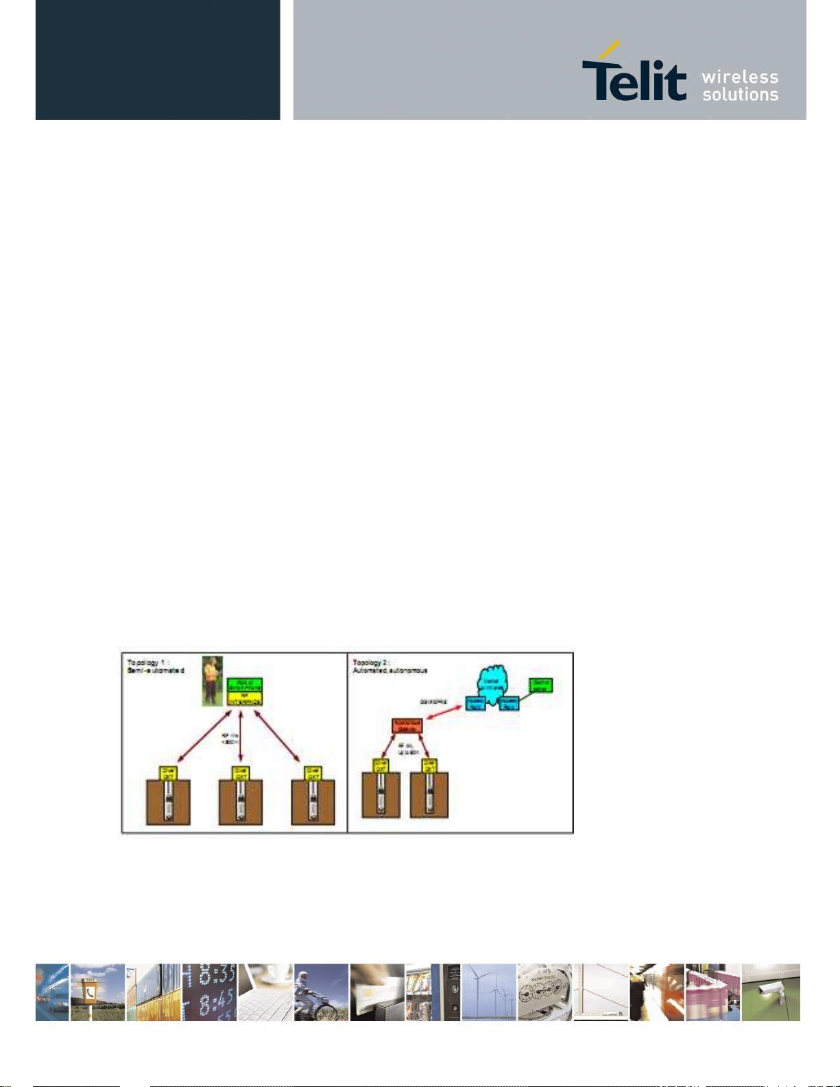
1.2 General System Architecture
The proposed product satisfy the topology scenarios 1 and 2 as specified in [1]
Figure 1 Topology Scenarios
Telit provides the gateway in two different configurations
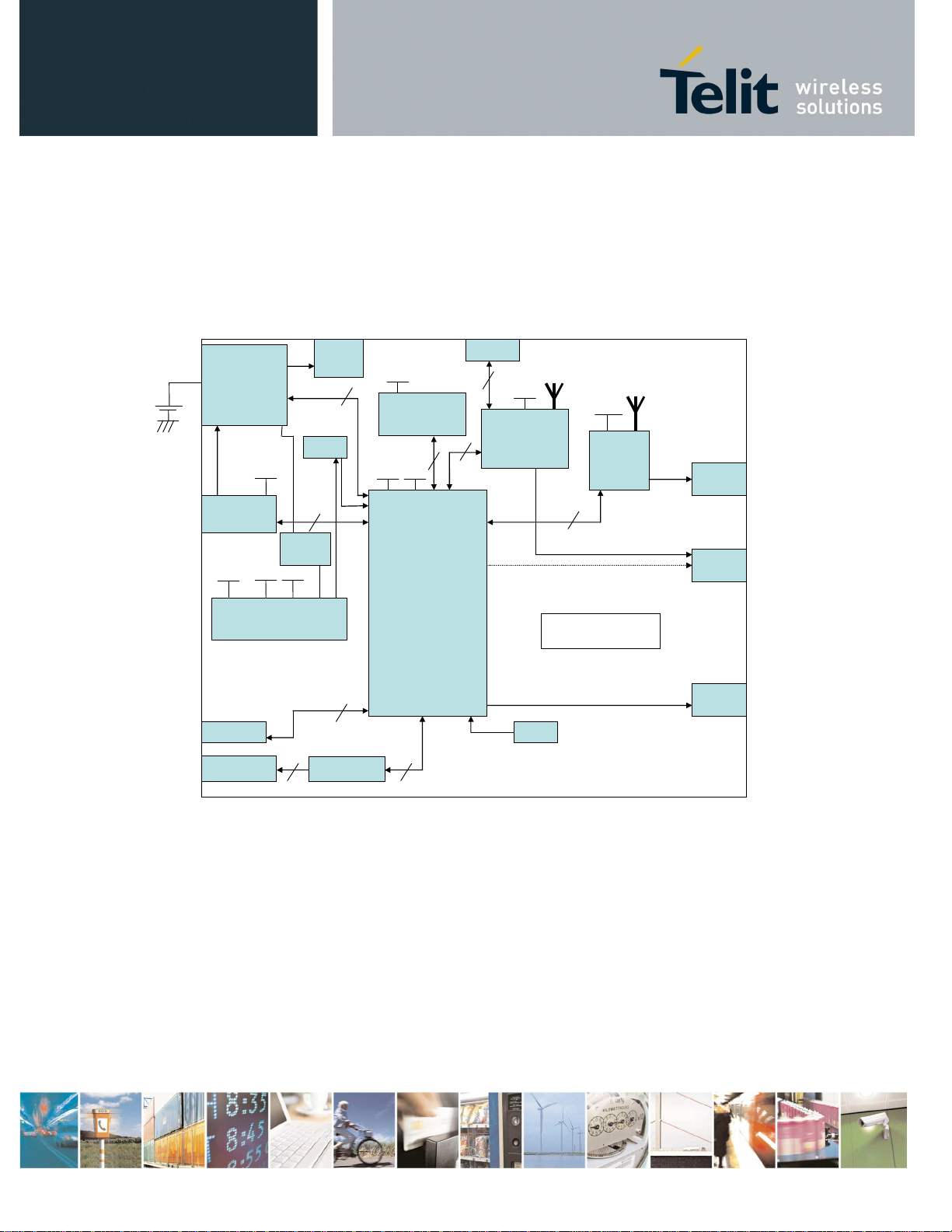
2 Configuration 1 (BG864-2.4)
SPI BT
CONNECT.
UART
#4 GPIO
BT Int.
Antenna
SPI
3.1V
3.1V
BT
ZE60
UART
#6 GPIO
Li-Ion
Batt.
+
Battery
Charger
+
Battery
Monitor
Mini-USB
Type B
3.8V
5.0V
3.1V
#5 GPIO
RTC
USB
device
ON/OFF
button
1.8V
LED 3
1.8V
MEMORY
AP DATA
3.1V
1.8V
ZB Int.
Antenna
LED 2
LED 1
Power
ARM9
Supply
JTAG
JTAG
UART
RS232
TRANSC.
Figure 2 Configuration 1 Block Diagram
2.1 Main Building Blocks
•
ARM9 ATMEL AT91SAM9260
•
Memories (Flash and RAM)
•
ZE60 (w/o internal antenna)
•
BT chip CSR BC63B239A04-IQD-E4
•
External connectors for:
o
Mini-USB device
o
RS232
Config. 1
RESET
button
LED 4
Reproduction forbidden without Telit Communications S.p.A. written authorization - All Rights Reserved page 6 of 75
o
Switch-slide Power-Supply
•
Internal antennas for:
o
BT
o
ZE60
•
Rechargeable Li-Ion battery
o
continuos charging application will be allowedthe battery charging will be stopped
when battery is completely charged.
•
Status Leds for:
o
BT
o
ZE60
o
Charger
o
ARM
•
Box
•
Power supply: external 4.5÷5.5V from mini-USB connector or 3.4÷4.2V from Li-Ion battery
•
Reset button
•
Operational Temperature: [-20°C +60°C]
•
Storage Temperature: [-40°C- +85°C]
2.2 Main Building Blocks features
•
ARM9 ATMEL AT91SAM9260
Based on the ARM926EJ-S™ ARM® Thumb® Processor
o
8-KByte Data Cache, 8-KByte Instruction Cache, Write Buffer
o
200 MIPS at 180 MHz
o
Memory Management Unit
o
EmbeddedICE™, Debug Communication Channel Support
o
External Bus Interface (EBI)
o
USB 2.0 Full Speed (12 Mbits per second) Device Port
o
USB 2.0 Full Speed (12 Mbits per second) Host Single Port in the 208-lead PQFP
o
Ethernet MAC 10/100 Base T
o
Fully-featured System Controller, including
o
Reset Controller, Shutdown Controller
o
Four 32-bit Battery Backup Registers for a Total of 16 Bytes
o
Clock Generator and Power Management Controller
o
Advanced Interrupt Controller and Debug Unit
o
Periodic Interval Timer, Watchdog Timer and Real-time Timer
o
Reset Controller (RSTC)
o
Clock Generator (CKGR)
o
Selectable 32,768 Hz Low-power Oscillator or Internal Low Power RC Oscillator on
o
Battery Backup Power Supply, Providing a Permanent Slow Clock
o
Power Management Controller (PMC)
•
Memories (Flash and RAM)
o
COMBO NAND SDRAM 128 MB FLASH/64 MB RAM
o
Memory will be shared for:
o
Code
o
Data
Reproduction forbidden without Telit Communications S.p.A. written authorization - All Rights Reserved page 7 of 75

o
Logging files (no dedicated memory will be provide for logging applications)
•
ZE60
o
Frequency band: 2400 - 2483.5 MHz
o
Power Supply:+2.4V-+3.6V
o
Output Power: 19dBm ± 1 dB on the whole band (selectable by software for compliance)
o
Consumption typ@3.6V :
o
Transmission :125mA
o
Reception : 35mA
o
Stand-by (32.768 khz On) : 2µA
o
Sleep (wake up on interruption): 1µA
o
Channel spacing: 5 MHz
o
Channel number : 16 , Channel 11 (2405MHz) → Channel 26 (2480MHz)
o
Technology : DSSS
o
Modulation: O-QPSK with half sine pulse shaping
o
Radio bit rate: 250 kbps
o
Sensitivity for PER(1%): -98dBm typ
o
Serial link:
o
Full Duplex, from 1200 to 115200 bps
o
7 or 8 bits, with or without parity, 1 or 2 stop bits
o
Protocol Type: RS-232, TTL level
o
Temperature: - 40+ 85°C
o
Relative humidity @ 25°C: 20-75%
o
Size: Rectangular 26 x 15 mm
o
Height: 3 mm
o
Weight: 1,7 g
o
PCB thickness: 0.8 mm
o
Components: All SMD components, on one side of the PCB.
o
Mounting: SMD, Half moons on the 4 external sides
o
Number of I/O pins: 30
•
Bluetooth
o
Fully qualified Bluetooth® v2.1 + EDR Specification
o
Piconet and scatternet support
o
Minimum external components
o
Low-power 1.5V operation, 1.8V to 3.6V I/O
o
Integrated 1.8V and 1.5V regulators
o
UART to 4Mbaud
o
SDIO (Bluetooth Type A)/CSPI interface
o
Deep sleep SDIO operation
o
40-lead 6 x 6 x 0.9mm 0.5mm pitch QFN
o
Support for IEEE 802.11 coexistence
o
Green ( RoHS and no antimony or halogenated
o
flame retardants)
Reproduction forbidden without Telit Communications S.p.A. written authorization - All Rights Reserved page 8 of 75
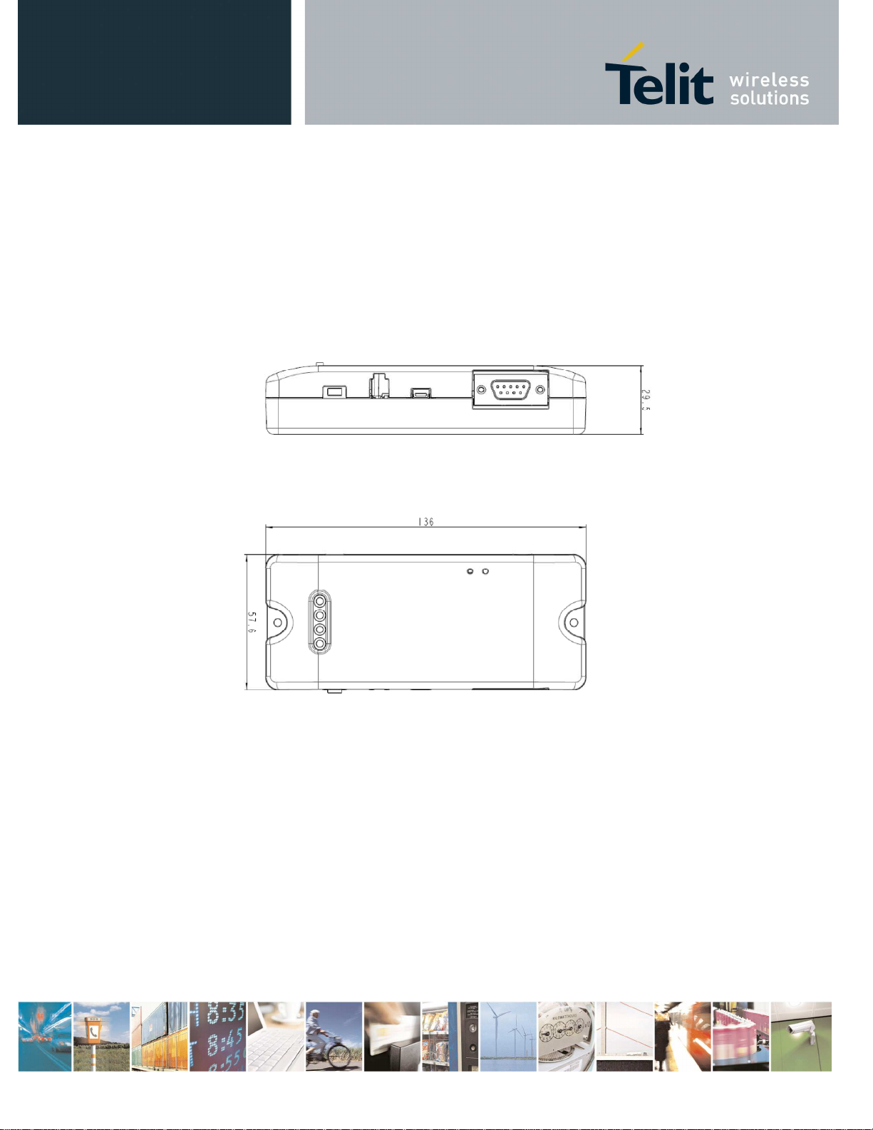
2.3 Physical Characteristics
2.3.1 Dimensions
The Telit BG864-2.4 dimensions are:
•
Length: 136 mm
•
Width: 57.6 mm
•
Thickness: 29.5 mm
Figure 3 - SWS-GW layout and dimensions
2.3.2 Environmental Characteristics
•
Operational Temperature: -20°C +60°C
•
Storage Temperature: -40°C +85°C
2.4 Interface Description
2.4.1 Overview
BG864-2.4 provides the following interface connectors:
•
RS232 serial interface
Reproduction forbidden without Telit Communications S.p.A. written authorization - All Rights Reserved page 9 of 75
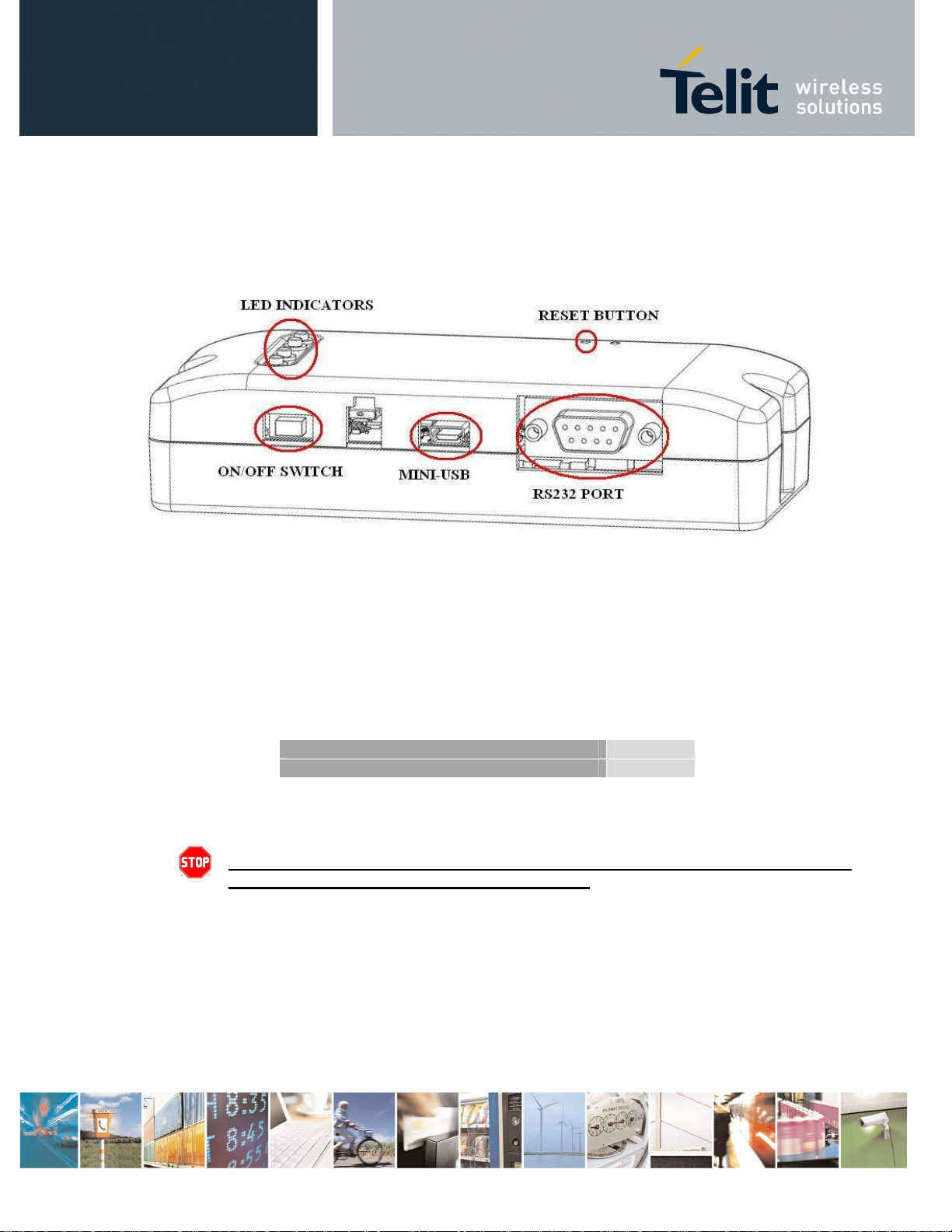
•
Mini-USB interface
•
ON/OFF Switch Slide
Furthermore, there are four led indicators (ARM, Bluetooth, Battery Charger and SR status) and one
push button (RESET).
Figure 4 – Interface overview
2.4.2 Supply Voltage
The BG864-2.4 can be supplied by an internal rechargeable Li-Ion battery or directly by the MINI-USB
port.
Power supply input is described in the following subsection and must fulfil the following requirements:
Li-Ion Batt. Supply Voltage Range 3.4÷4.2V
Mini USB Supply Voltage Range 4.5÷5.5V
Table 1 – Supply Voltage
Danger – Operating voltage range must never be exceeded; care must be taken
in order to fulfill Min/Max voltage requirements.
2.4.3 Battery source
Power is supplied by an internal rechargeable Li-Ion battery.
Battery voltage range is 3.4 ÷ 4.2V.
If the Gateway is connected via the Mini-USB to an external PC (or power supply) then the battery will
be automatically recharged by means of integrated battery charger circuitry.
Reproduction forbidden without Telit Communications S.p.A. written authorization - All Rights Reserved page 10 of 75
The battery capacity should be sized on the customer’s application and battery life requirements.
Warning – Do not charge the Li-Ion battery out of temperature range of
0
÷45°C.
Battery connector must be Molex 87439-0200 or compatible.
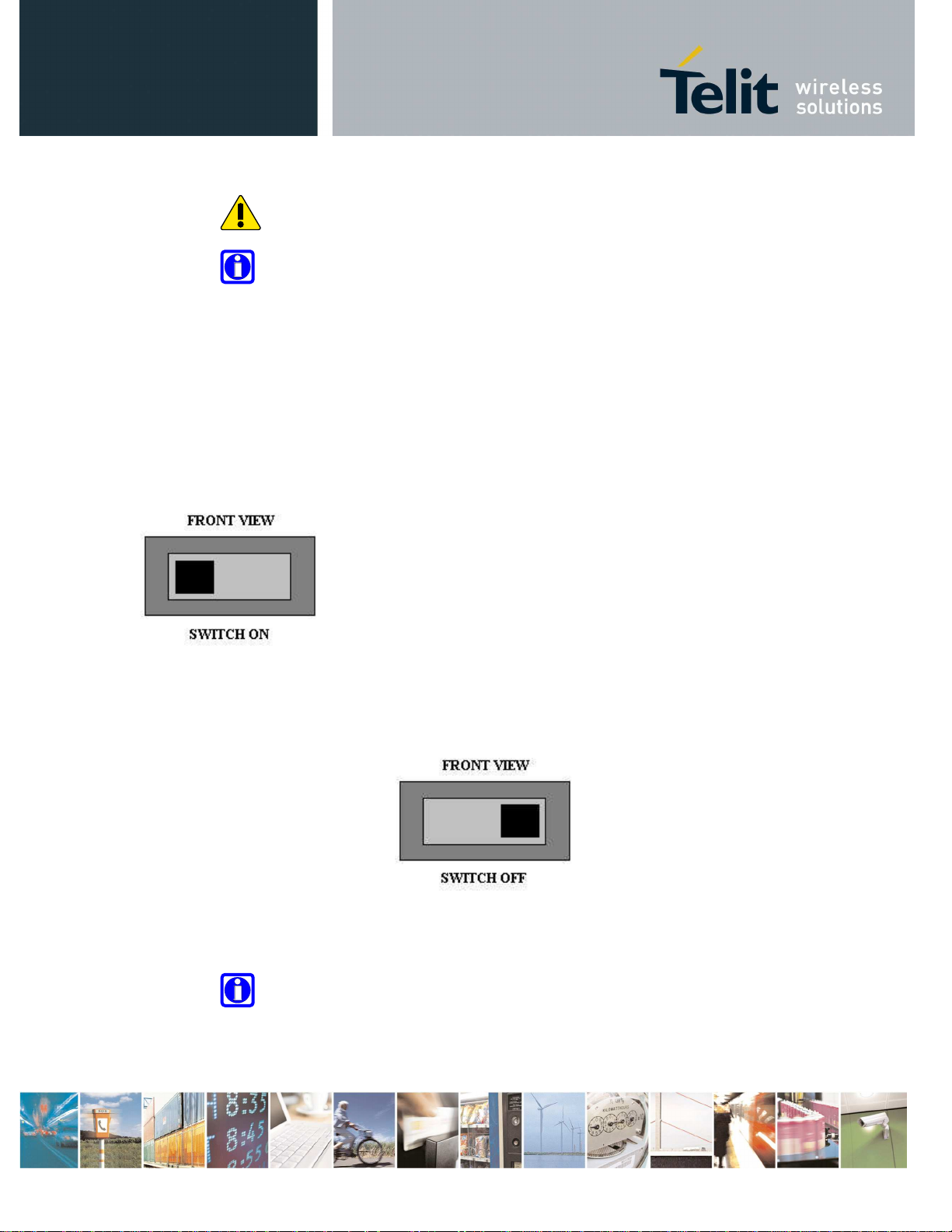
2.4.4 Switching the BG864-2.4 ON and OFF
The switch on/off slide button is used to turn ON or OFF the gateway
2.4.4.1 Switching ON Procedure
The BG864-2.4 switches on when slide switch is moved on the left.
.
BG864-2.4 operating system is operational after about 20 seconds from the power-on.
2.4.4.2 Switching OFF
The BG864-2.4 switches off when slide switch is moved on the right.
The BG864-2.4 can be switched off either by disconnecting the power supply from the MINI-USB port
and the battery or by software command.
It is suitable a software switch-off command before disconnect the power supply.
Note- When the slide switch is in OFF position and the battery is
connected, battery charge continues to function if BG864-2.4 is connect to
an external supply from the MINI-USB port
Reproduction forbidden without Telit Communications S.p.A. written authorization - All Rights Reserved page 11 of 75
Bluetooth
ANTENNA SPECIFICATIONS
Frequency Range
Bandwidth
Peak
Gain
Average Gain
Impedance
Peak Efficiency
Average Efficiency
VSWR
Frequency Range
Bandwidth
Peak
Gain
Average Gain
Impedance
Peak Efficiency
Average Efficiency
VSWR
2.4.5 Antenna
In BG864-2.4 there are two internal antennas, one for Bluetooth and one for the Short Range
technology.
2.4.5.1 Bluetooth Antenna specifications
The Bluetooth antenna for BG864-2.4 has the following specifications:
2.4 GHz
2.4 – 2.5 GHz
2.2 dBi
1.9 dBi
50 ohm
74%
72%
< 2:1
Table 2 – Bluetooth Antenna specifications
2.4.5.2 Short Range Antenna Specifications
The short range antenna for BG864-2.4 has the following specifications:
Short Range ANTENNA SPECIFICATIONS
2.4 GHz
2.4 – 2.5 GHz
2.2 dBi
1.9 dBi
50 ohm
74%
72%
< 2:1
Table 3 – Short Range Antenna specifications
2.4.6 Serial Port
The RS232 standard interface serves to connect a PC, Data Terminal Equipment (DTE) or an
application, wich acts as host controller for the BG864-2.4 with all its functions.
Serial port connects directly the host controller with the UART-Debug of the ARM chip inside BG864-
2.4.
RS232 level translator is present on board.
Reproduction forbidden without Telit Communications S.p.A. written authorization - All Rights Reserved page 12 of 75
PIN Signal
Description
PIN Signal
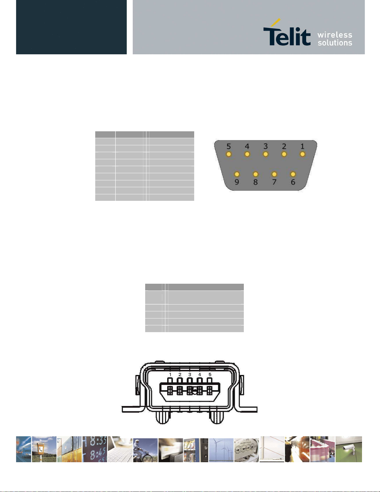
2.4.6.1 RS232 standard interface connector
The connector mounted in the BG864-2.4 is a standard RS232 Sub-D 9pin female with the following
characteristics:
Baud rate from 300 to 115.200 bit/s
Autobauding (300 to 38.400 bit/s)
Pin-out (refers to DTE side):
1 - NC
2 RXD RX Output
3 TXD TX Input
4 - NC
5 GND GROUND
6 - NC
7 - NC
8 - NC
9 - NC
Table 3 – serial port pin-out
To connect to a host controller, a pin-to-pin 9pin cable with D9 type connectors on both sides is
needed (1 male & 1 female). Shielding of this cable is recommended and its length shall not exceed
3 m.
(FRONT VIEW)
2.4.7 Mini USB type connector
Pin-out of Mini-USB connector is shown in the following table:
1
2 DDM
3 DDP
4 5 GND
Table 4 – Mini USB pin-out
Figure 5 - Mini-USB connector front view
USBCNX /
Charger Power Supply
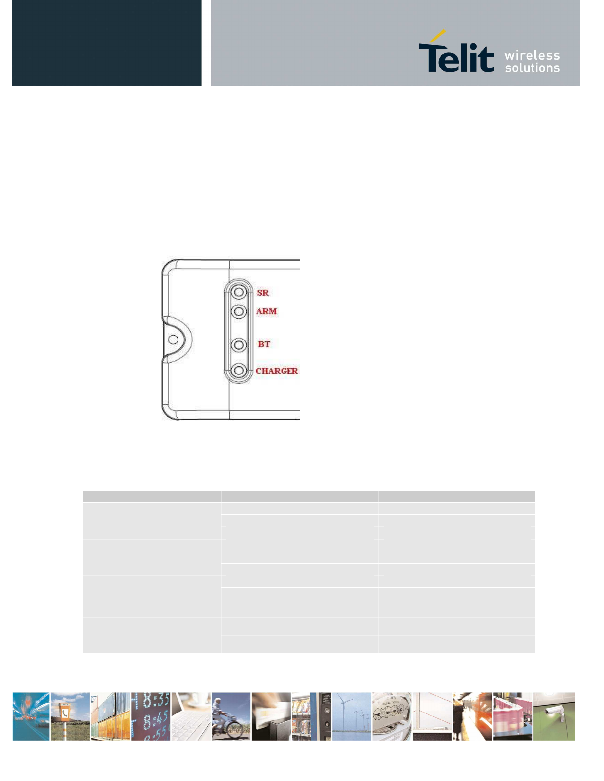
2.4.8 LEDindicators
The BG864-2.4 has four led indicators:
1. Bluetooth status,
2. ARM status,
3. SR status
4. charger status.
Figure 6 - LED indicators
2.4.8.1 Bluetooth LED indicator
The follow table shows information on the status of the four led indicators:
LED ID LED STATUS DEVICE STATUS
Permanently OFF OFF
SR
ARM
BT
BATT. CHARG.
TABLE 5 – LED indicators
Blinking Comm. Session
Permanently ON Wake-up Session
Permanently OFF OFF/Stand-by
Blinking Operating
Permanently ON Boot State
Permanently OFF OFF
Blinking Connected
Permanently ON Network Scan
Permanently ON Battery charging
Permanently OFF Charge Complete
Reproduction forbidden without Telit Communications S.p.A. written authorization - All Rights Reserved page 14 of 75
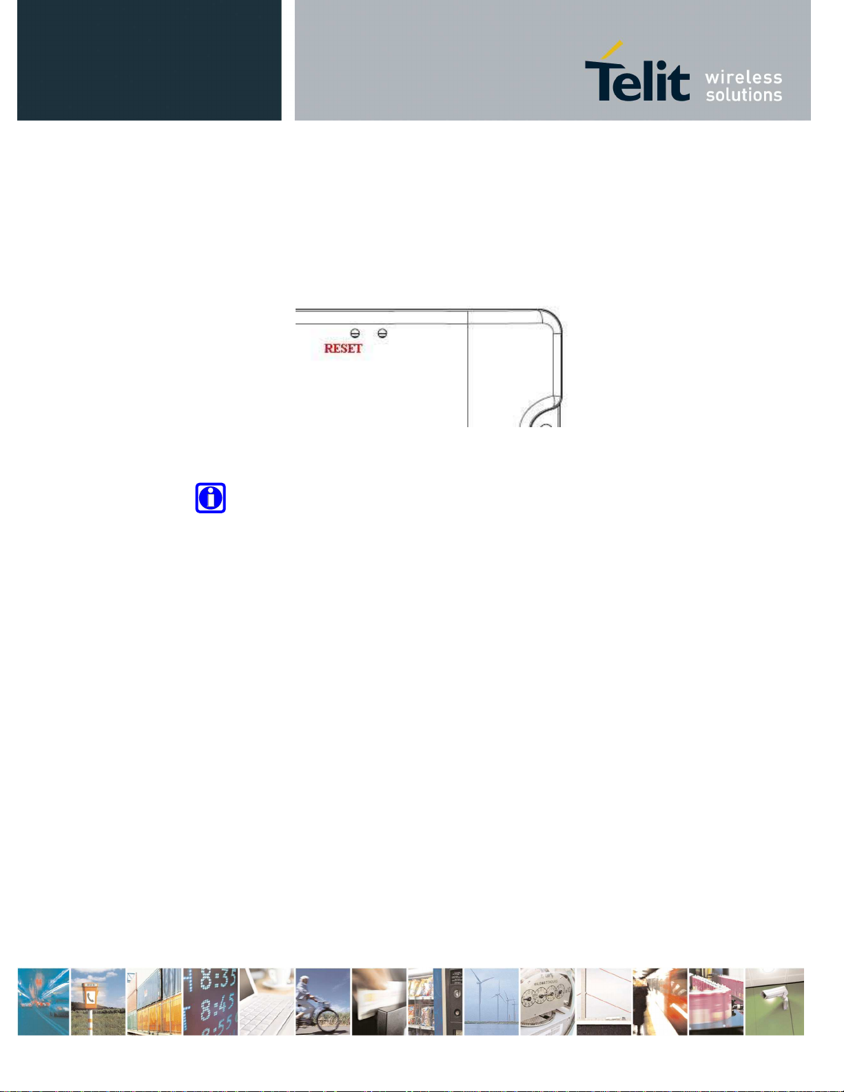
2.4.9 Push Button
In the surface of the BG864-2.4 box there is one hole to allowing with a sharp object to push the
reset button inside.
Reset Button is connected to the reset signal of the ARM processor. Pushing this button force the
reset and make the BOOT of the processor.
Figure 7 - Push Buttons
Note- The second hole near reset button’s hole is unused
Reproduction forbidden without Telit Communications S.p.A. written authorization - All Rights Reserved page 15 of 75
3 Configuration 2 (GG864-2.4)
1.8V
5 - 15V
No-Recharg.
Batt.
+
Mini-USB
Type B
5.0V_B
3.8V
3.1V
PIC
JTAG
RS232
3.1V
1.8V
Power
Supply
RTC
USB
device
#3 GPIO
#3 GPIO
JTAG
TRANSC.
MEMORY
AP DATA
3.1V
1.8V
ARM9
UART
#3 GPIO
UART
USB host
3.8V
GC/UC
RESET
button
WAKEUP
button
5.0V_B
864
3.1V
ZE60
UART
#6 GPIO
RF
Config. 2
RF
LED 2
LED 1
SIM CARD
LED 4
ZB Ext.
Antenna
L.R. Ext.
Antenna
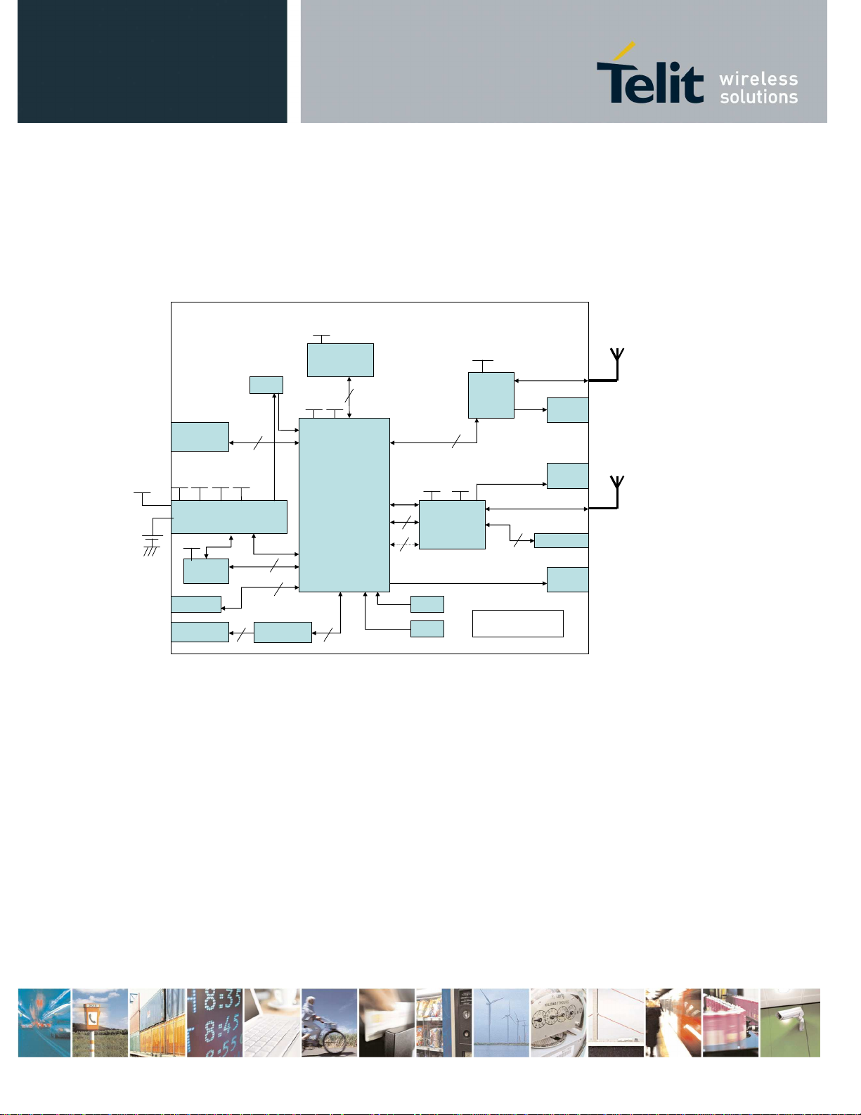
Figure 8 Configuration 2 Block Diagram
3.1 Main Building Blocks
•
ARM9 ATMEL AT91SAM9260
•
Memories (Flash and RAM)
•
ZE60
•
GSM module Unified FF (GC864)
•
SMA connectors for External antennas:
o
GSM
o
ZE60
•
external I/F connectors
o
Power supply
o
RS232
Reproduction forbidden without Telit Communications S.p.A. written authorization - All Rights Reserved page 16 of 75

o
SIM card holder
o
Mini-USB
•
Status leds for:
o
GSM
o
ZE60
o
ARM
•
Box
•
Reset button and Wake-Up button
•
Power supply voltage 5-15V
•
Operational Temperature: [-20°C +70°C]
•
Storage Temperature: [-40°C- +80°C]
3.2 Main Building Blocks features
•
GC864 GSM module
o
Quad-band EGSM 850/900/1800/1900 MHz
o
Control via AT commands according to GSM 07.05, 07.07 and Telit enhancements
o
Serial Port multiplexer GSM 7.10
o
SIMM access profile
o
TCP/IP stack access via AT commands
o
Supply voltage range: 3.22-4.5V DC
o
Dimensions: 30x36.2x3.2 mm
o
Weight: 6.1 grams
o
RoHS compliant
o
Extended temperature range
- -40°C to 85°C (operational)
- -40°C to 85°C (storage)
o
Sensitivity:
- -107 dBm (typ.) @ 850/900 MHz
- -106 dBm (typ.) @ 1800/1900 MHz
o
Power consumption (typ.)
- Power off: <26 uA
- Idle(registered, power saving): 2.6 mA
- Dedicated mode: 200 mA
- GPRS cl.10: 370 mA
o
Output power
- Class 4 [2W] @ 850/900 MHz
- Class 1 [1W] @ 1800/1900 MHz
Reproduction forbidden without Telit Communications S.p.A. written authorization - All Rights Reserved page 17 of 75
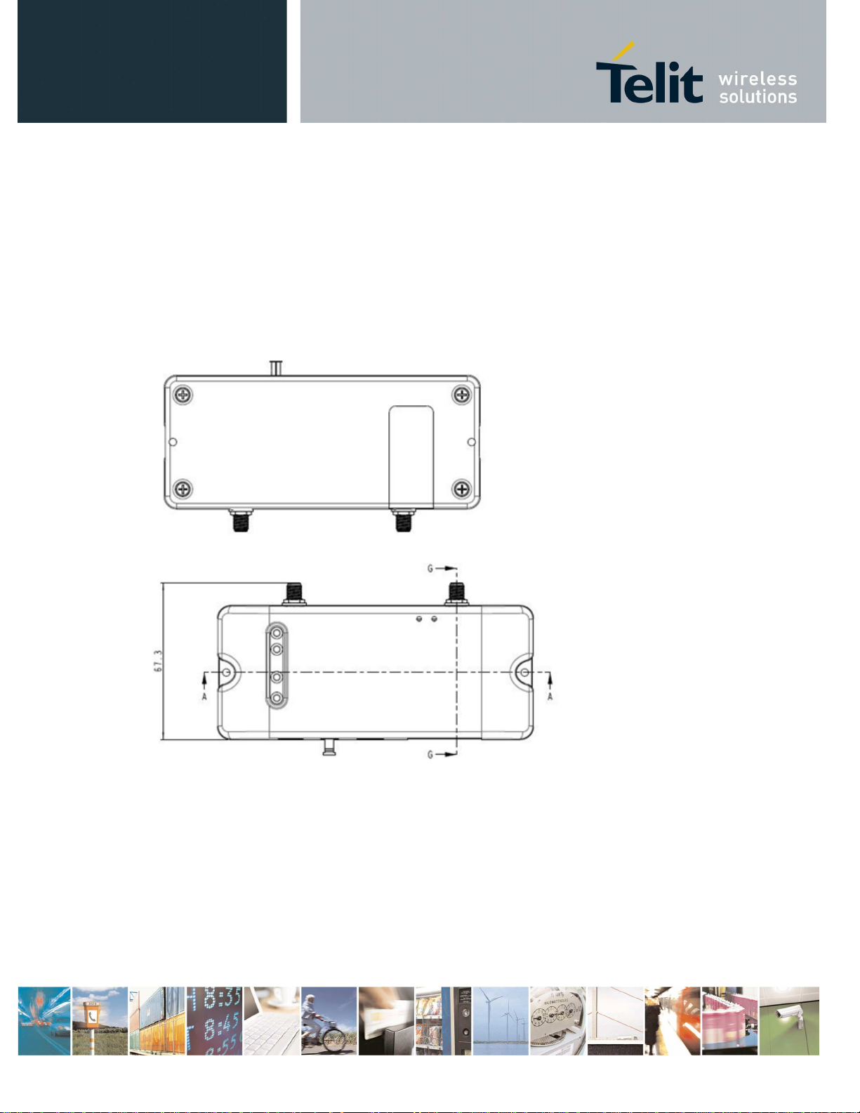
3.3 Physical Characteristics
3.3.1 Dimensions
The Telit GG864-2.4 dimensions are:
•
Housing Length: 136 mm
•
Overall Length: 136 mm
•
Width: 57,6 mm
•
Thickness: 29,5 mm
Figure 9 - SWS-GW layout and dimensions
Reproduction forbidden without Telit Communications S.p.A. written authorization - All Rights Reserved page 18 of 75
Nominal Supply Voltage
Min Supply Voltage
Max supply Voltage
3.4 Interface Description
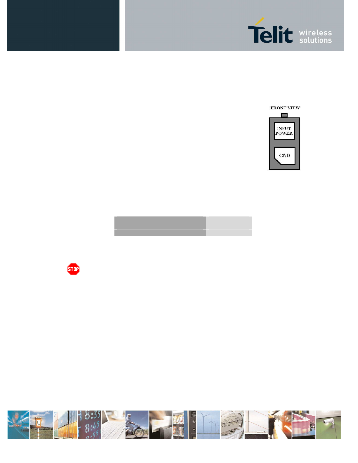
3.4.1 Power connector
The power connector on the left side of the terminal is a Molex 2-pins connector (part no.: 43045-
0210).
Pin description:
•
GND = Ground reference
•
Input Power = 5 - 15 VDC
3.4.2 Supply Voltage
The external power supply must be connected to power supply input as described in the following
subsection and must fulfil the following requirements:
12 volts
5 volts
15 volts
Table 5 – Supply Voltage
Danger – Operating voltage range must never be exceeded; care must be taken
in order to fulfill Min/Max voltage requirements.
3.4.3 Battery source
The external power supply could be sourced by an external no rechargeable battery.
Battery voltage range is 5 – 15V.
The battery capacity should be dimensioned on the customer’s application and battery life
requirements.
3.4.4 Switching the GG864-2.4 ON and OFF
3.4.4.1 Switching ON
The GG864-2.4 switches on automatically each time the power supply is connected the first time or reconnected.
Reproduction forbidden without Telit Communications S.p.A. written authorization - All Rights Reserved page 19 of 75
GSM ANTENNA REQUIREMENTS
Gain
Note- When the power supply cable is disconnected, it is recommended to
wait approximately 5 seconds before applying the power again.
3.4.4.2 Switching OFF
The GG864-2.4 can be switched off either by disconnecting the power supply or by software
command.
It is suitable a software switch-off command before disconnect the power supply cable.
Warning – Please note that hardware power off should be done only after
a proper GSM logoff. Any GSM device is request to issue a “detach”
request at turning off.
3.4.5 Antenna
3.4.5.1 Antenna Output
Warning – BEFORE connecting the GG864-2.4 to a power supply source, suitable
antennas shall be connected and properly installed.
The antenna has to be installed with care to avoid any interference with other electronic devices
and has to guarantee a minimum distance from the body (20 cm). in case this requirement cannot
be satisfied, the system integrator has to assess the final product against the SAR regulation.
For a good efficiency of the antenna and a minimum interference with other electronic systems, a
space of min. 40 cm around the radiating part should be left free of electrically conducting materials.
The less distance and the fewer obstacles between the SWS-GW antenna and the antenna of the
GSM/GPRS network base station, the less power is radiated by the gateway and the better signal
quality is achieved.
3.4.5.2 Antenna Connectors
The GG864-2.4 includes two SMA bulkhead female, class 4 (2W) co-axial connectors for the two
external antennas.
3.4.5.3 GSM Antenna Requirements
The GSM antenna for GG864-2.4 device shall fulfill the following requirements
:
Reproduction forbidden without Telit Communications S.p.A. written authorization - All Rights Reserved page 20 of 75
Frequency Range
Bandwidth
Standard Dual Band GSM/DCS frequency
range or Standard Quad Band GSM/DCS/OCS
frequency range if used for all four bands
70 MHz in GSM850, 80 MHz in GSM &
170MHz in DCS & 140 MHz PCS band
< 3 dBi
Impedance
Input power
VSWR absolute max
VSWR recommended
Short Range ANTENNA REQUIREMENTS
Frequency Range
Bandwidth
Gain
Impedance
VSWR recomme
nded
50 ohm
> 2 W peak power
<= 10:1
<= 2:1
Table 6 – GSM Antenna requirements
3.4.5.4 Short Range Antenna Requirements
The short range antenna for GG864-2.4device shall fulfill the following requirements:
2.4 GHz
2.30 – 2.50 GHz
< 4 dBi
50 ohm
<= 1.5:1
Table 7 – Short Range Antenna requirements
3.4.6 Serial Port
The RS232 standard interface serves to connect a PC, Data Terminal Equipment (DTE) or an
application, witch acts as host controller of the SWS-GW with all its functions.
Serial port connects directly the host controller with the UART-Debug of the ARM chip of SWS-GW.
RS232 level translator is present on board.
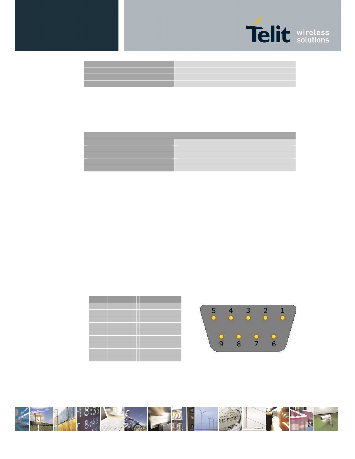
3.4.6.1 RS232 standard interface connector
The connector mounted in the SWS-GW is a standard RS232 Sub-D 9pin female with these
characteristics:
Baud rate from 300 to 115.200 bit/s
Autobauding (300 to 38.400 bit/s)
Pin-out (refers to DTE side):
PIN Signal Description
1 - NC
2 RXD RX Output
3 TXD TX Input
4 - NC
5 GND GROUND
6 - NC
7 - NC
8 - NC
9 - NC
Table 8 – serial port pin-out
To connect to a host controller, a pin-to-pin 9pin cable with D9 type connectors on both sides is
needed (1 male & 1 female). Shielding of this cable is recommended and its length shall not exceed
3 m.
(FRONT VIEW)
PIN Signal
Figure
10 - Mini
-
USB connector front view
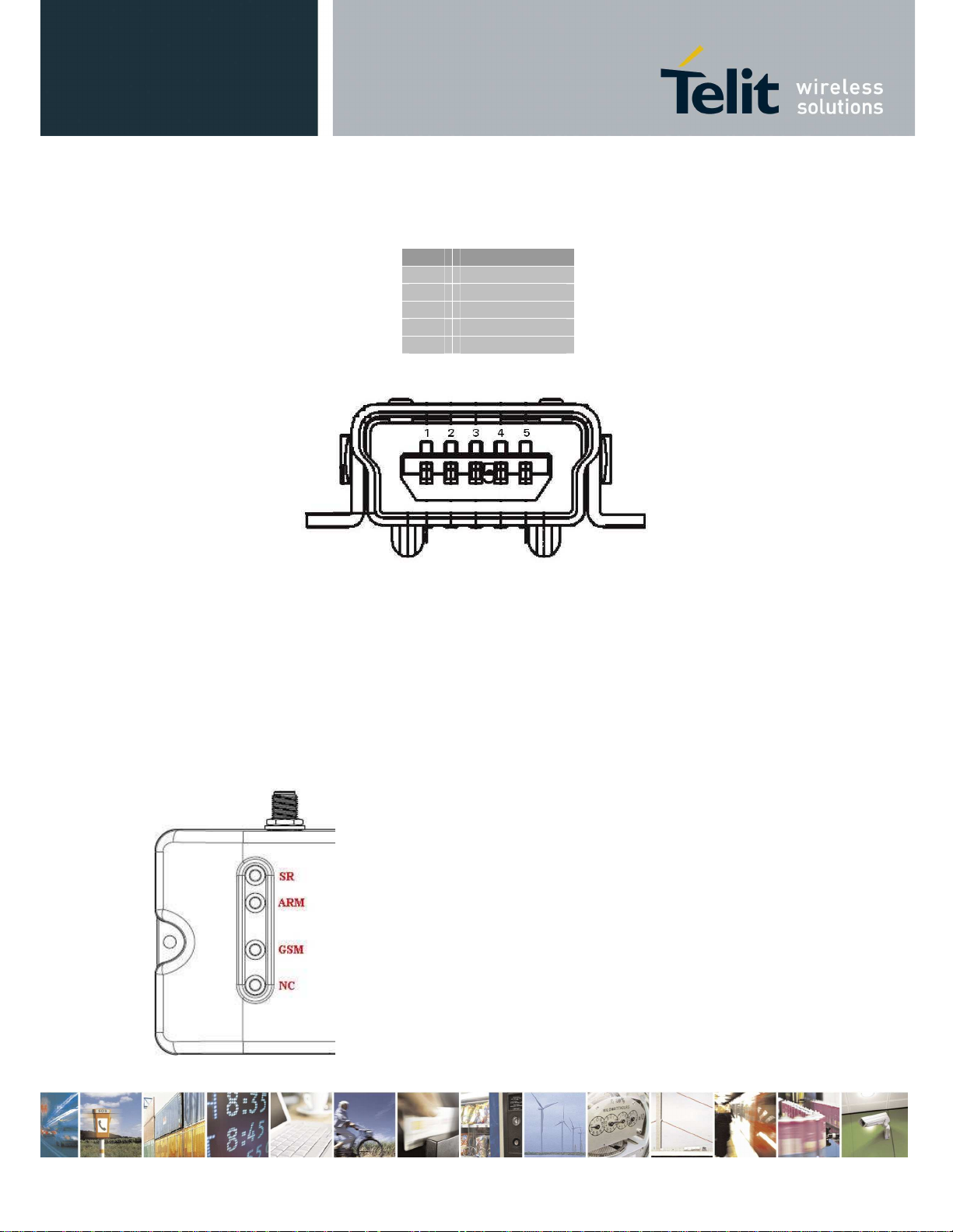
3.4.7 Mini USB type connector
Pin-out of Mini-USB connector is shown in the following table:
1 USBCNX
2 DDM
3 DDP
4 5 GND
Table 9 – Mini USB pin-out
3.4.8 LED indicators
The GG864-2.4 has three led indicators:
1. GSM status
2. ARM status
3. SR status (fourth led indicator is not connected in this configuration).
Figure 11 - LED indicators
LED STATUS
DEVICE STATUS
3.4.8.1 GSM LED indicator
The red LED shows information on the network service availability and call status.
LED STATUS DEVICE STATUS
permanently on a call is active
fast interrupt sequence
(period 0,5s, Ton 1s)
slow interrupt sequence
(period 0,3s, Ton 3s)
permanently off device off
Net search / Not
registered / turning off
Registered full service
TABLE 10 – GSM LED indicator
3.4.8.2 ARM LED indicator
The red LED shows information on the ARM status:
LED STATUS DEVICE STATUS
Permanently OFF
Blinking Operating
Permanently ON Boot State
TABLE 11 – ARM LED indicator
OFF/Stand-by
3.4.8.3 Short Range LED indicator
The red LED shows information on the network service availability and call status.
Permanently OFF
Blinking
Permanently ON Wake-up Session
TABLE 12 – SR LED indicator
Reproduction forbidden without Telit Communications S.p.A. written authorization - All Rights Reserved page 23 of 75
OFF
Comm. Session
 Loading...