

Page 1

Mod.08
Telit Technical Documentation
SE150A4
EVB User Guide
1VV0301694 Rev. 1 – 2021-01-29
18 2017-01 Rev.0
Page 2

SE150A4 Smart Module EVB User Guide
PRODUCTS
PART NUMBER
APPLICABILITY TABLE
SE150A4 SMART EVB MAINBOARD (3990150671)
SE150A4-NA INTERFACE FOR SMART EVB
SE150A4-EU INTERFACE FOR SMART EVB
1VV0301694 Rev. 1 Page 2 of 44 2021-01-29
Page 3

SE150A4 Smart Module EVB User Guide
Contents
APPLICABILITY TABLE 2
CONTENTS 3
1. INTRODUCTION 6
Scope 6
Audience 6
Contact Information, Support 6
Text 6
Related Documents 7
2. GENERAL PRODUCT DESCRIPTION 8
Overview 8
Content of the Kit 8
3. FUNCTIONAL DESCRIPTION 11
Block Diagram 11
Main Connectors and Devices Layout 12
Switch and Jumpers Settings 13
4. POWER SUPPLY 15
Power Supply Source Selection 15
Power consumption monitoring 18
Battery Charging 18
5. PERIPHERALS 19
Display (LCM) 19
Touch Panel 20
Main USB 20
UART 21
USIM Interfaces 22
SD CARD 23
Control buttons 24
POWER Key 24
1VV0301694 Rev. 1 Page 3 of 44 2021-01-29
Page 4

SE150A4 Smart Module EVB User Guide
5.8.1. RESET Key 24
5.8.2. VOLUME Keys 25
5.8.3. Keys Combinations 25
Sensors 26
5.9.1. Accelerometer 26
5.9.2. Proximity 26
Audio 27
5.10.1. Digital Microphone 27
5.10.2. De-Noising Microphone 28
5.10.3. Handset 28
5.10.4. Headset 29
5.10.5. Speaker 30
5.10.6. Vibrator 30
ADC 31
VCOIN 31
GPIO 31
Board to Board Connectors 32
6. SE150A4 SMART MODULE INTERFACE 34
Description 34
Main Connectors and Devices Layout 34
Camera 35
6.3.1. Front Camera 35
6.3.2. Rear Camera 35
RF Connectors 36
USB BOOT 36
7. PRODUCT AND SAFETY INFORMATION 38
Copyrights and Other Notices 38
7.1.1. Copyrights 38
7.1.2. Computer Software Copyrights 38
Usage and Disclosure Restrictions 39
7.2.1. License Agreements 39
7.2.2. Copyrighted Materials 39
7.2.3. High Risk Materials 39
1VV0301694 Rev. 1 Page 4 of 44 2021-01-29
Page 5

SE150A4 Smart Module EVB User Guide
7.2.4. Trademarks 39
7.2.5. Third Party Rights 40
7.2.6. Waiwer of Liability 40
Safety Recommendations 40
8. ACRONYMS 42
9. DOCUMENT HISTORY 43
1VV0301694 Rev. 1 Page 5 of 44 2021-01-29
Page 6

SE150A4 Smart Module EVB User Guide
Danger: This information MUST be followed or catastrophic
1. INTRODUCTION
Scope
This document introduces the EVB for the SE150A4 Smart Module and describes all its
characteristics and functionalities. All the features and solutions detailed in this
document are applicable to all SE150A4 Smart Module variants, where SE150A4 Smart
Module refers to the variants listed in the applicability table.
Audience
The Telit SE150A4 Smart Module EVB is a development board
designed for engineers, programmers and developers who are looking to:
• Develop and test applications based on current and future Telit Smart Module
families via Android
• Debug and/or Improve Android applications based on Telit Smart Modules
Contact Information, Support
For general contact, technical support services, technical questions and report
documentation errors contact Telit Technical Support at:
•
•
•
•
Alternatively, use:
For detailed information about where you can buy the Telit modules or for
recommendations on accessories and components visit
Our aim is to make this guide as helpful as possible. Keep us informed of your comments
and suggestions for improvements.
Telit appreciates feedback from the users of our information.
http://www.telit.com/support
http://www.telit.com
Text
1VV0301694 Rev. 1 Page 6 of 44 2021-01-29
equipment failure or personal injury may occur.
Page 7
SE150A4 Smart Module EVB User Guide
Warning: Alerts the user on important steps about the module
Note/Tip:
Electro-static Discharge:
Module Name
Description
1VV0301698
SE150A4 Smart Module Hardware User Guide
1VV0301695
SE150A4 Smart Module SDK User Guide
integration.
Provides advice and suggestions that may be useful when
integrating the module.
Notifies the user to take proper grounding
Table 1: Symbol Conventions
precautions before handling the product.
All dates are in ISO 8601 format, that is. YYYY-MM-DD.
Related Documents
1VV0301694 Rev. 1 Page 7 of 44 2021-01-29
Page 8
SE150A4 Smart Module EVB User Guide
Item
Quantity
Telit SE150A4 Smart Module EVB Mainboard
1
Power Supply adapter
1
SMA female to UFL cable (length: 120mm)
3
Multi Band RF antenna (with SMA male connector)
3
2. GENERAL PRODUCT DESCRIPTION
Overview
The Telit SE150A4 Smart Module is a multi-mode and multi-band wireless smart
module, which is based on Qualcomm QCM2150 platform. It includes baseband, memory,
RF front end and required circuitry to support rich multimedia features, global locationbased service, wireless connectivity, and air interface standards including GSM, WCDMA,
and LTE.
With higher integration to reduce PCB surface area, time-to-market, and BOM costs,
Telit SE150A4 Smart Module will help drive wireless products adoption in more industry
around the world.
SE150A4 Smart Module is based on Android operating system and it helps customers to
develop handheld devices without host MCU or processors.
The SE150A4 Smart Module EVB is a system permitting the customer to evaluate the
module’s functionalities and to test them with a first set of peripherals such a Display,
Camera and sensors.
The SE150A4 Smart Module EVB is integrated with the following items:
• LCM
• Proximity Sensor and Ambient Light sensor
• Accelerometer (G-Sensor)
• Two Camera (Front / Rear)
• Analog / Digital audio
• Two SIM card holders
• One USB interface for the main Module’s port
• Two UART ports available on an USB hub adapter (for debug purposes)
• 4 buttons (Power Key, Reset, VOL+ and VOL-)
• T-FLASH card interface
• Battery charger
Content of the Kit
The Telit SE150A4 Smart Module EVB kit consists of the following Items:
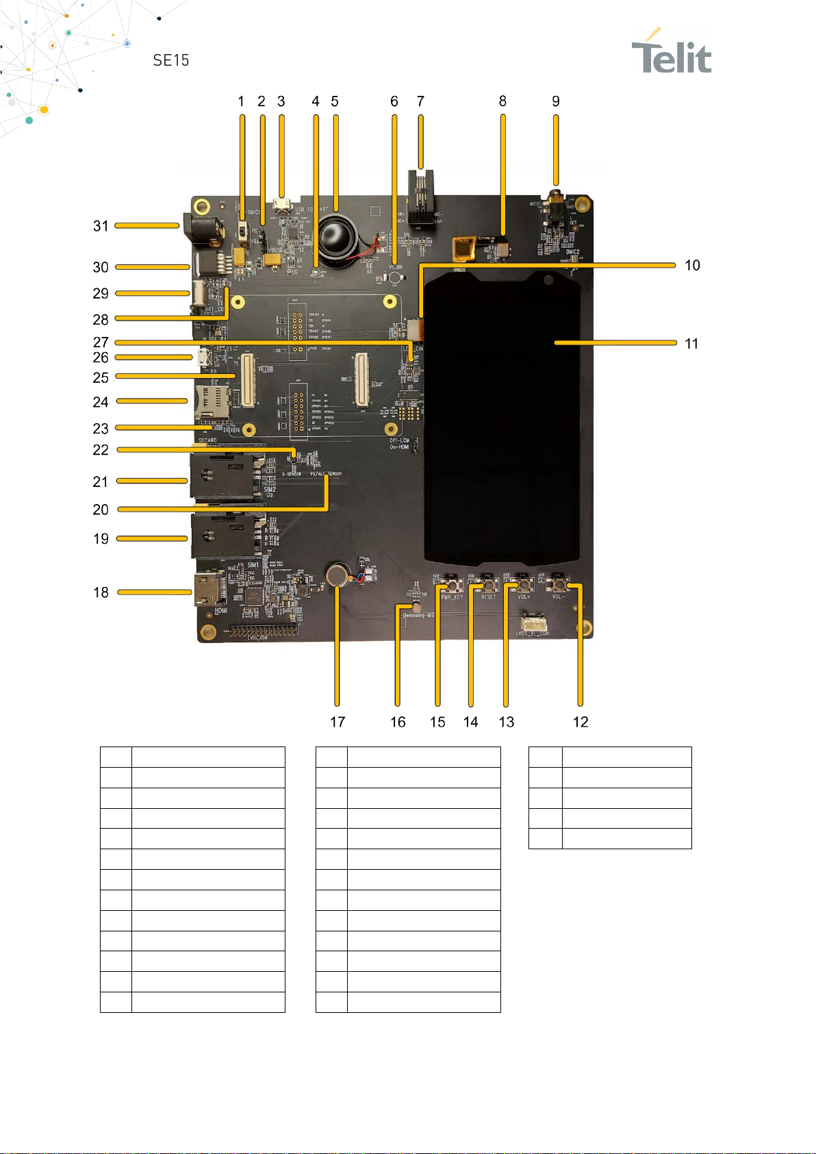
The EVB Mainboard is shown in the following image:
1VV0301694 Rev. 1 Page 8 of 44 2021-01-29
Page 9
SE150A4 Smart Module EVB User Guide
1
14
27
2
15
28
3
16
29
4
17
30
5
18
31
6
19
7
Earpiece and MIC
20
PS/ALS Sensor
8
TP Interface
21
SIM Card slot 2
9
22
10
23
11
24
12
25
13
26
Power Switch
VBUS
UART
Power-On indicator
Speaker
VCOIN
Headphone Jack
LCM Interface
LCM
Volume -
Volume +
Reset button
Power button
Denoising MIC
Vibrator
HDMI Port
SIM Card slot 1
G-Sensor
SD Card test points
SD Card slot
TE Board connector
Micro USB port
Backlight driver
Q102
Battery connector
LDO
DC Jack
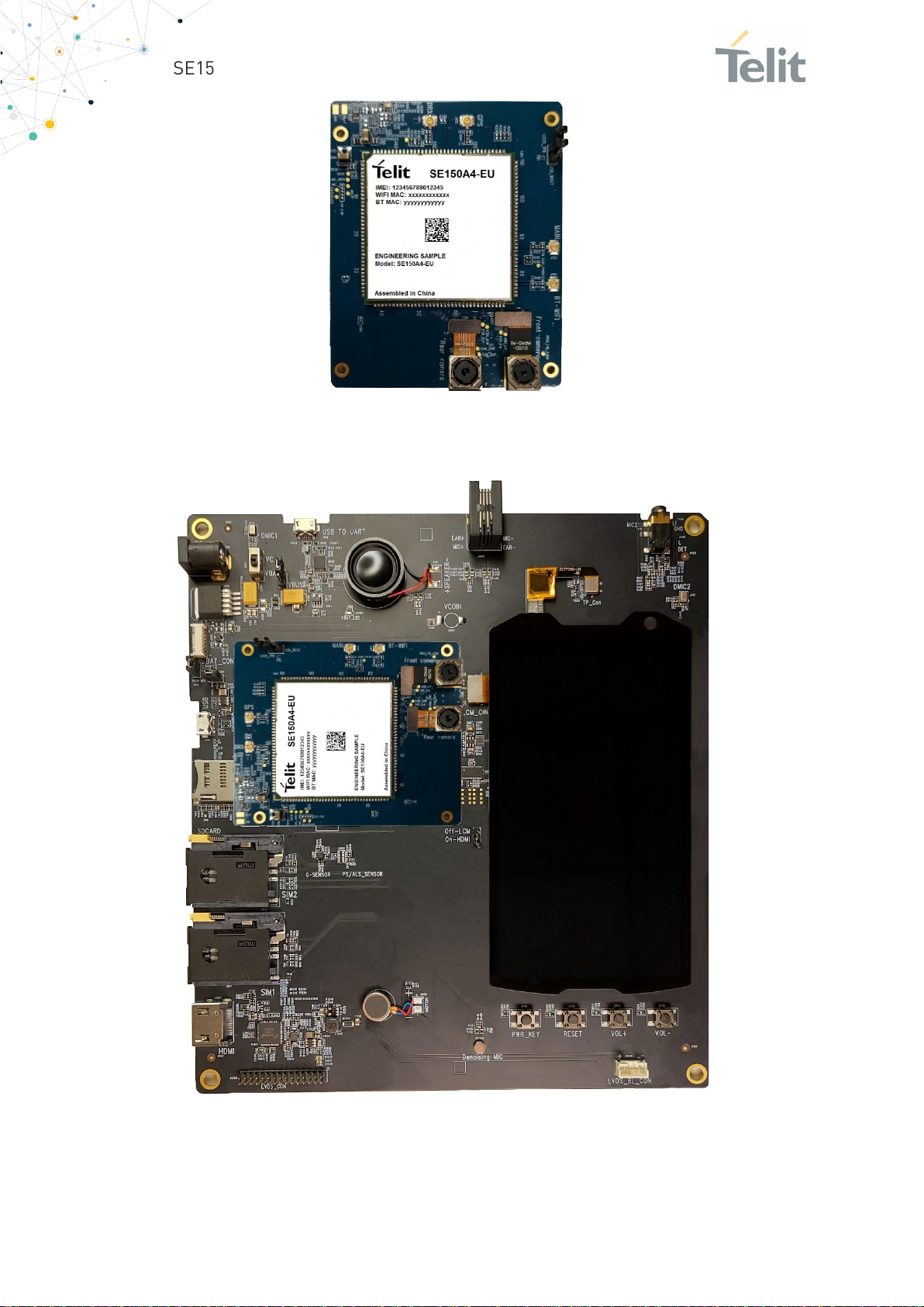
The EVB can host one SE150A4 TE board, which is shown below:
1VV0301694 Rev. 1 Page 9 of 44 2021-01-29
Page 10
SE150A4 Smart Module EVB User Guide
The picture below shows how to install the SE150A4 TE board on to the EVB:
1VV0301694 Rev. 1 Page 10 of 44 2021-01-29
Page 11
SE150A4 Smart Module EVB User Guide
3. FUNCTIONAL DESCRIPTION
Block Diagram
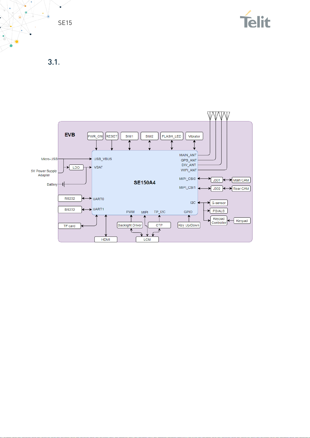
The SE150A4 Smart Module EVB is a motherboard that permits to connect and use the
Telit SE150A4 Smart Module’s Interfaces. It can be split into several functional blocks
depending on the implemented function; the following image is detailn the block
diagram:
1VV0301694 Rev. 1 Page 11 of 44 2021-01-29
Page 12
SE150A4 Smart Module EVB User Guide
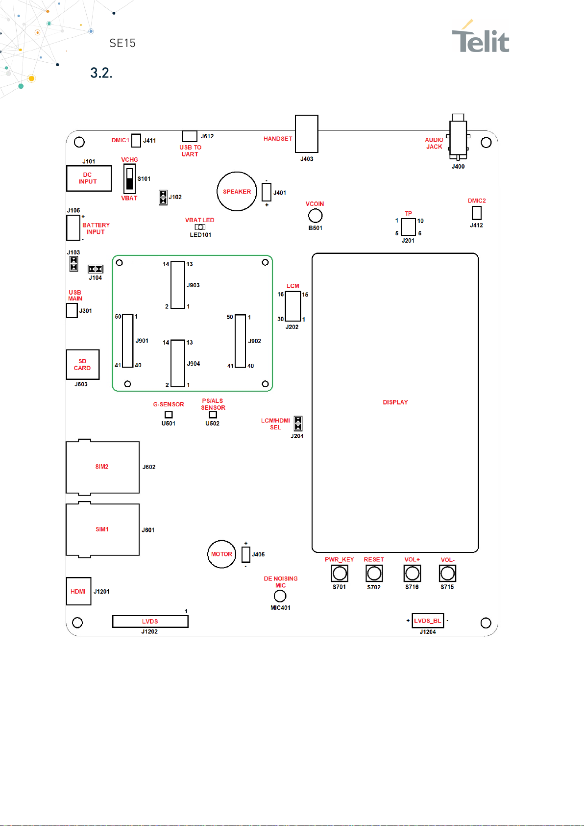
Main Connectors and Devices Layout
The following Image is showing the position of the main connectors/devices on the EVB:
1VV0301694 Rev. 1 Page 12 of 44 2021-01-29
Page 13
SE150A4 Smart Module EVB User Guide
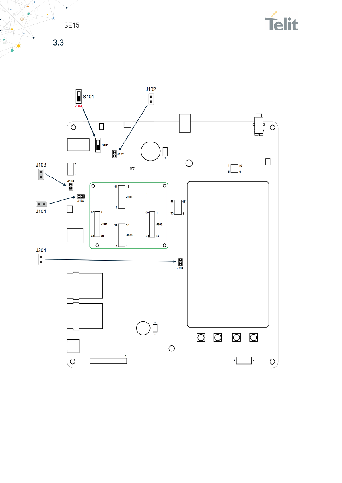
Switch and Jumpers Settings
The following Image is showing the position of the Switches and Jumpers on the EVB and
their factory default settings:
1VV0301694 Rev. 1 Page 13 of 44 2021-01-29
Page 14

SE150A4 Smart Module EVB User Guide
Jumper /
Switch
Default
Setting
Function
Statuses
J102
consumption measurements.
J103
CLOSED when supplying EVB with the DC
Battery (using connector J105)
J104
measurements.
J204
S101
Permits to select if 5V DC supply
VBATT
The Jumpers and Switches functional description is described in the following table:
In series to 5V DC when connected
Open
to VUSB via S101.
Can be used to perform Power
OPEN when S101 is on VBAT position
CLOSED when S101 is on VCHG position
Closed
Closed
Open
VBAT
The jumper when closed is adding a
Pull down resitor of 47Kohm to the
BAT_THERM line.
In series to VBAT provided to the
module. Can be used to perform
Power consumption
Permits to select which display bus
to use (LCM display or HDMI/LVDS)
from DC INPUT is connected to the
VUSB line (Module’s main USB port)
or to the main DCDC adapter for
INPUT connector
OPEN when supplying the EVB with the
CLOSED in most of the uses
OPEN when required to unconnect Module’s
VBAT
OPEN if LCM Display is used
CLOSED if HDMI/LVDS port is used
VBAT if 5VDC is applied to internal DCDC for
VBAT
CHR if HDMI/LVDS port is used
1VV0301694 Rev. 1 Page 14 of 44 2021-01-29
Page 15
SE150A4 Smart Module EVB User Guide
4. POWER SUPPLY
Power Supply Source Selection
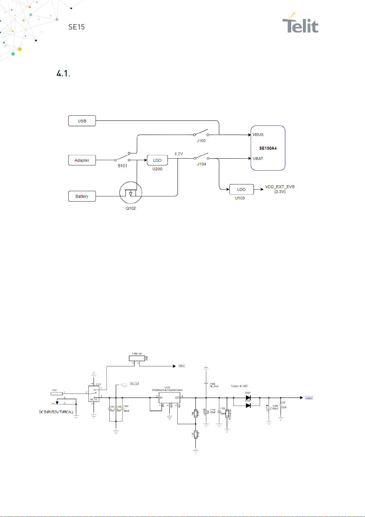
The EVB can be powered from power adapter or battery depending on required use case.
The following block diagram describes the power supply path.
If the 5V power adapter is connected to EVB, switch S101 needs to be moved to VBAT
position, and jumpers J102 and J104 need to be closed to power up the EVB.
If the battery (3.5V ~ 4.4V) is connected to EVB, jumper J104 needs to be closed, to power
up the EVB.
MOSFET Q102 prevents the adapter and the battery from being supplying the power to
EVB at the same time.
There is a Power-on indicator LED101 on EVB. This LED glows in red color when the DC
power supply or battery power supply is normal.
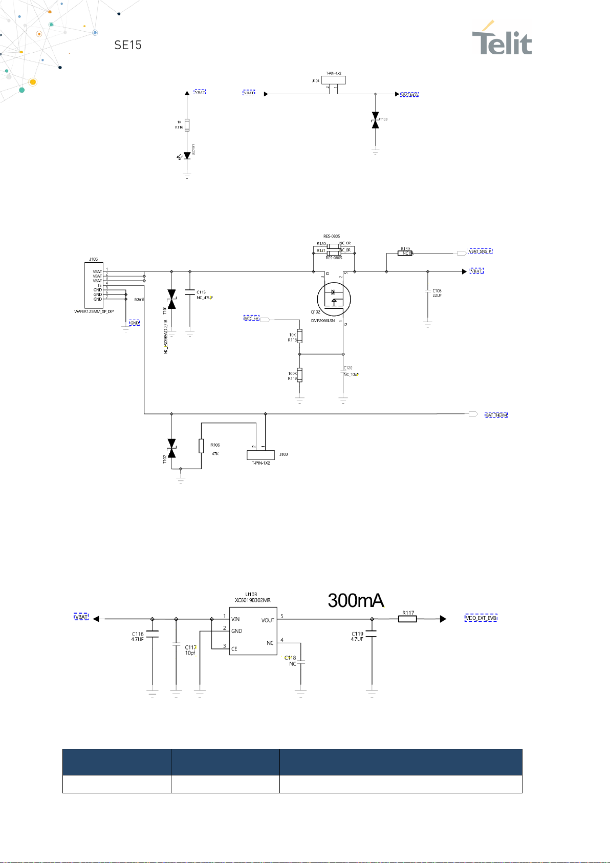
The following circuit shows the DCDC section:
1VV0301694 Rev. 1 Page 15 of 44 2021-01-29
Page 16
SE150A4 Smart Module EVB User Guide
Peripheral
Connector
Description
LCM
J201 LDO6_1P8(125pin), LDO17_2P85(129pin)
The Battery connector and switching circuit:
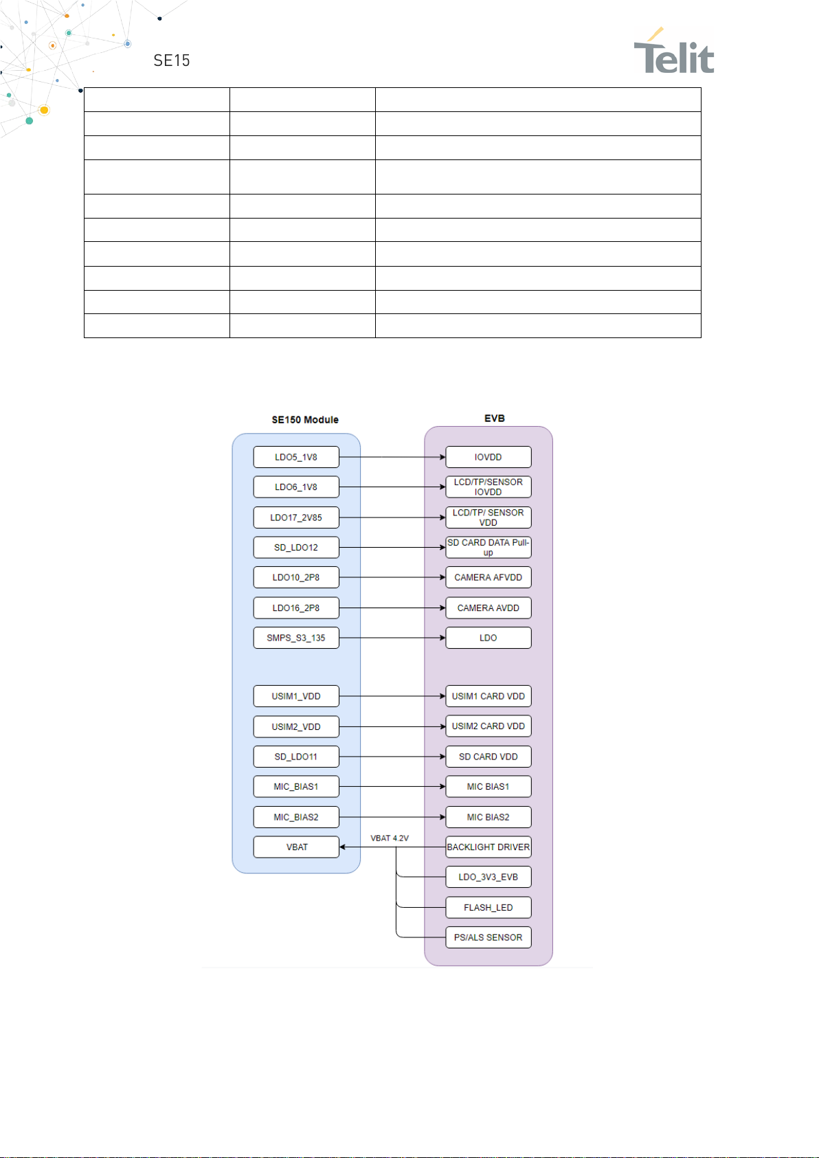
The EVB internally supplies its peripherals with some LDO outputs (1.8V, 2.85 and VSIM)
from the SE150A4 Smart Module and with a 3.3V LDO (VDD_EXT_EVB).
The 3.3V LDO schematic:
The following table is detailing the involved LDOs:
1VV0301694 Rev. 1 Page 16 of 44 2021-01-29
Page 17
SE150A4 Smart Module EVB User Guide
Backlight
U201
VBAT
Capacitive Touch Panel
J202 LDO17_2P85(129pin), LDO6_1P8(125pin)
Flashlight
U301 LED301
VBAT
Camera
J301 J302
LDO6_1P8(125pin) for Camera DVDD
for Camera AVDD
G-sensor
U501
LDO6_1P8(125pin)
ALS/PS Sensor
U701
VBAT, LDO17_2P85(129pin), LDO6_1P8(125pin)
Vibrator
J402 VIB_DRV_N(28pin)
TF Card
J603 LDO11_SDC (38pin)
SIM Card
J601 J602
VREG_L14_UIM1(26pin),
LED
D101
VBAT
The power distribution diagram is shown below:
LDO17_2P85(129pin)
VREG_L15_UIM2(21pin)
1VV0301694 Rev. 1 Page 17 of 44 2021-01-29
Page 18

SE150A4 Smart Module EVB User Guide
Note/Tip: To measure the SE150A4 Smart Module current
Power consumption monitoring
In order to facilitate the user to measure the current consumption of the module, there
are two test points (VBAT and GND) on SE150A4 Smart Module-TE board. Supply power
to VBAT and GND test points on the by removing the jumper J104 in the EVB.
consumption, EVB needs to be powered separately, so that the
LCM will work normally..
Battery Charging
The EVB has a battery connector J103, battery can be charged either from DC adapter or
micro USB port. Battery connection is optional to operate EVB. Battery could be useful
for field trials, drive tests, and demos to avoid unexpected power cuts.
If both adapter and battery are connected, EVB will be powered by adapter and battery
can be charged. Note that jumpers J102 and J104 need to be closed and S101 is moved
to VBAT position. If battery charging function is not required, remove jumper on J102.
If the EVB is powered by adapter, it is necessary to pull down BAT_THERM (module pin
VBATT_THERM, Pin 134) to GND with a 47K resistor, otherwise charging and power
supply will be abnormal.
When battery is used to supply power to EVB, the value of R106 need to be equal to the
internal NTC resistance of the battery at normal temperature, hence R106 = 47KΩ.
1VV0301694 Rev. 1 Page 18 of 44 2021-01-29
Page 19
SE150A4 Smart Module EVB User Guide
Item
Description
Display Type
Amorphous silicon TFT (a-Si TFT)
Display Colors:
16.7M
Resolution:
720*1280
Pixel Pitch:
0.08625(H)*0.08625(V)
LCM Dricver IC:
ILI9881D
Display Mode:
Transmissive /Normally Black
Luminance:
430cd/m2(typ)
Contrast:
900:1
LCM Interface Type:
MIPI DSI video mode
LCM Pin Numbers:
30
Pin Pitch:
0.4Pitch
Inoput Voltage:
VDD:2.8 or 3.3V,IOVCC:1.8V or VDD
Backlight Type and Color:
LED backlight /white
Backlight
If=40mA
5. PERIPHERALS
Display (LCM)
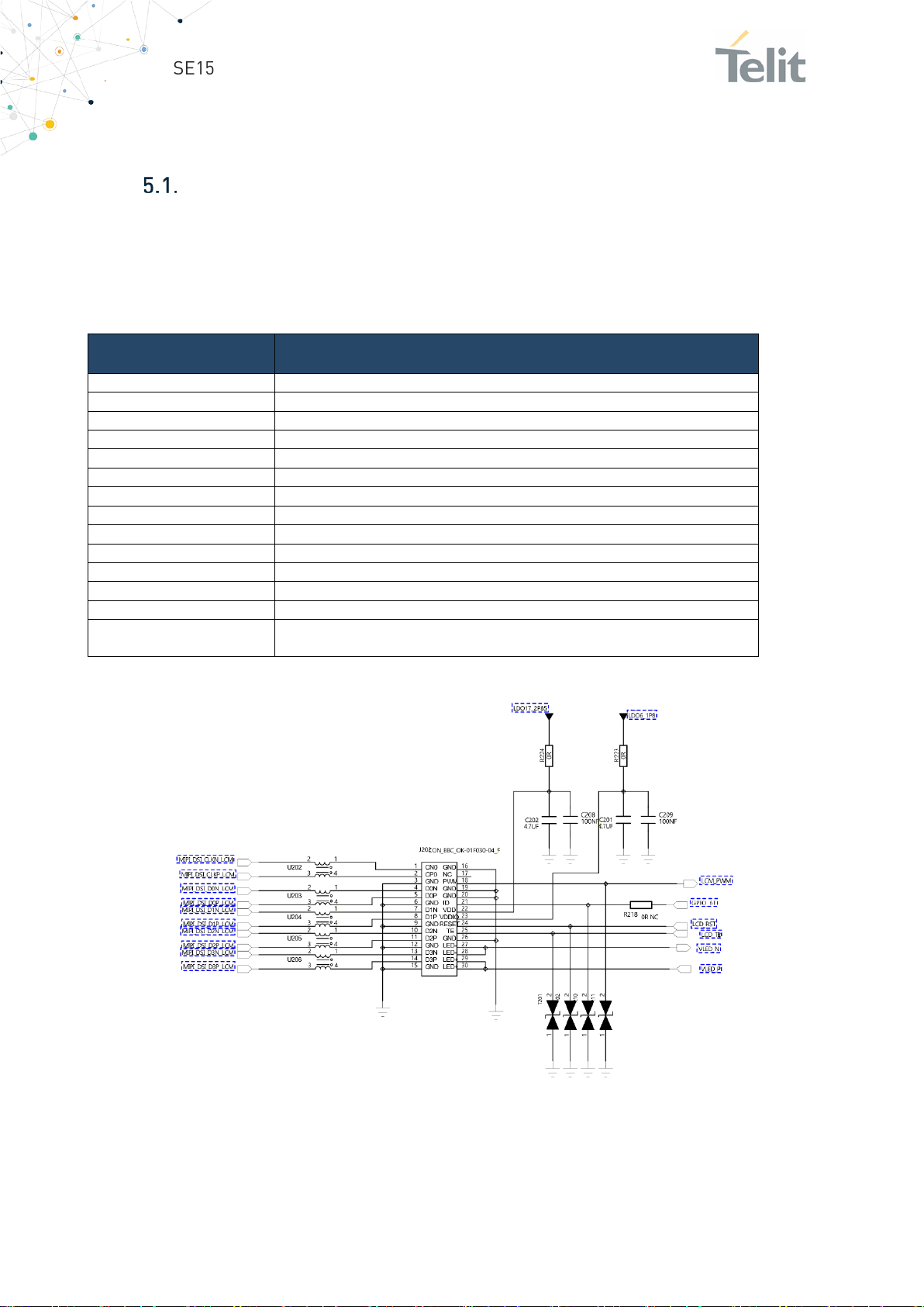
The most important peripheral for a Smart Module is the Display (or also called LCM:
“Liquid Crystal Monitor”) that includes also some additional items like the Capacitive
Touch Panel (CTP) and the backlight driver. Details of the LCM used with this EVB are
below:
The
LCM
is
12 LED, 2 groups in parallel, 6 LEDs in series in each group,Vf=19.2V,
connected to the EVB through the J202 connector:
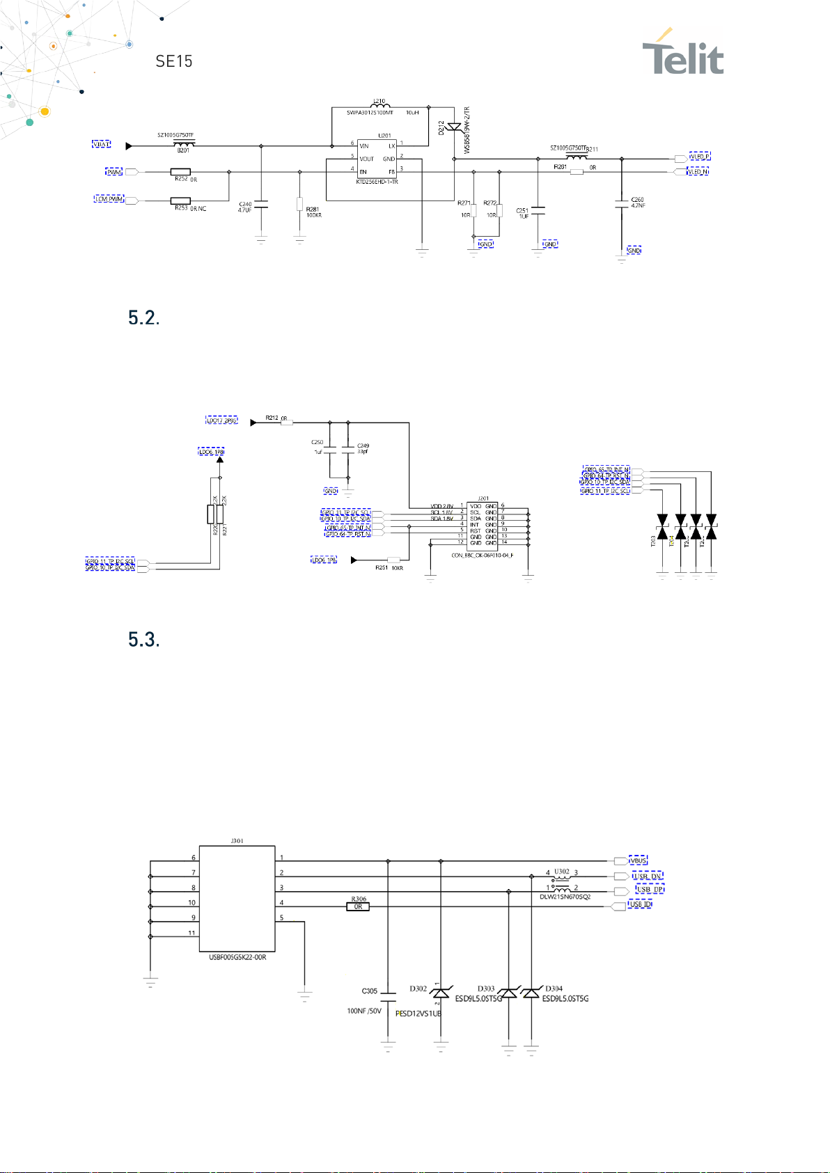
The following schematic is related to the Backlight driver:
1VV0301694 Rev. 1 Page 19 of 44 2021-01-29
Page 20
SE150A4 Smart Module EVB User Guide
Touch Panel
The display is integrated with a Capacitive Touch Panel (CTP) driver GT5688.
This part is connected to the EVB through the J201 connector as shown below.
Main USB
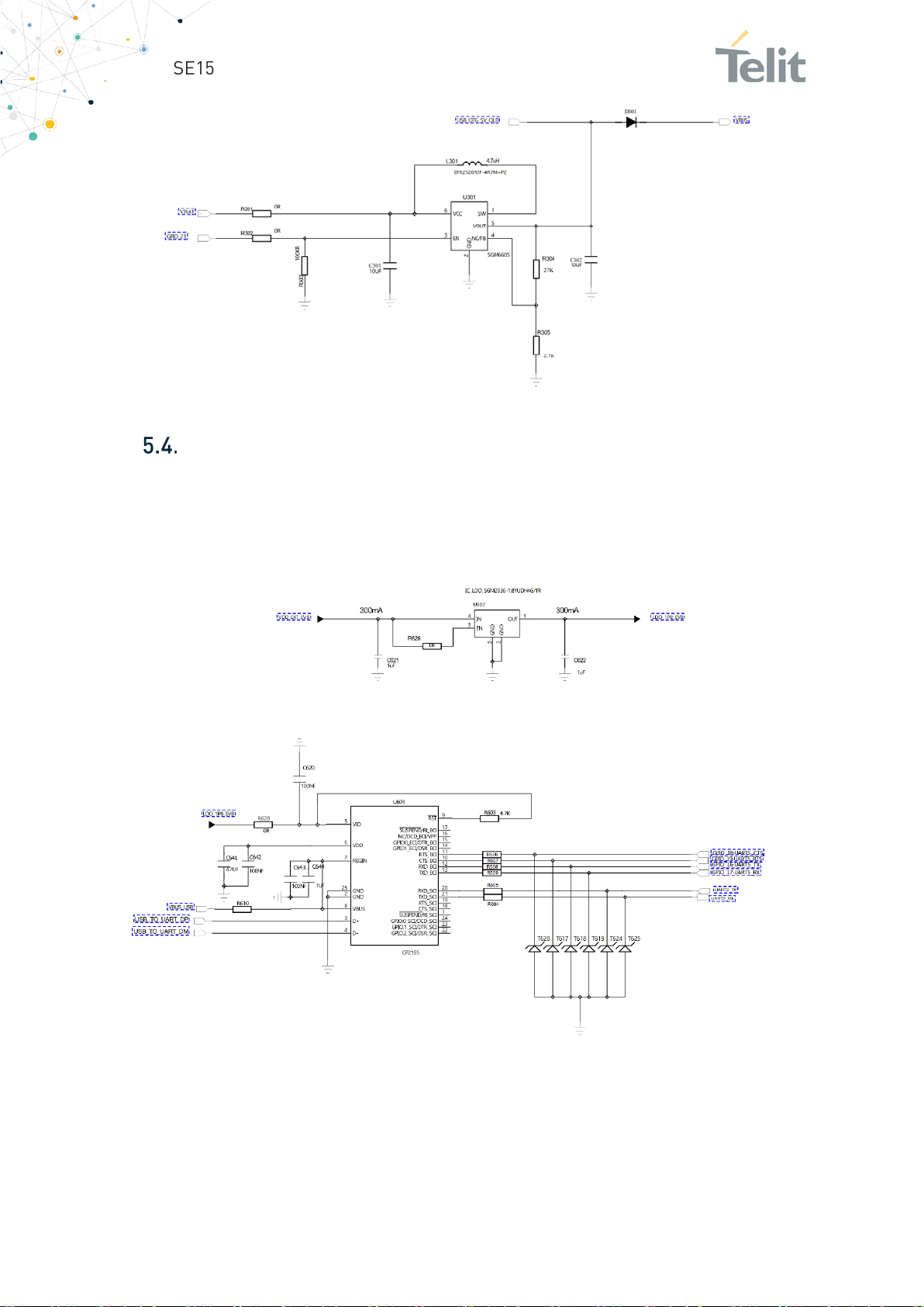
The module is equipped with an USB port used to interface the Modem, to perform
firmware download and for debug/trace purposes.
The SE150A4 Smart Module USB port is connected to Micro USB port on EVB available
on connector J301. Battery can also be charged from this port. It supports BC1.2
charging standard, maximum charging current can reach 1.44A.
Related circuit is below.
The 5V boost circuit for the OTG function is below:
1VV0301694 Rev. 1 Page 20 of 44 2021-01-29
Page 21
SE150A4 Smart Module EVB User Guide
UART
The module has two UART ports; the first UART has flow control (CTS and RTS), second
UART doesn't has flow control for debug or data communication. The two UART ports
are connected to UART to USB converter chip CP2105. When user connects USB cable
to J612, two COM ports can be seen in Device manager.
1VV0301694 Rev. 1 Page 21 of 44 2021-01-29
Page 22
SE150A4 Smart Module EVB User Guide
USIM Interfaces
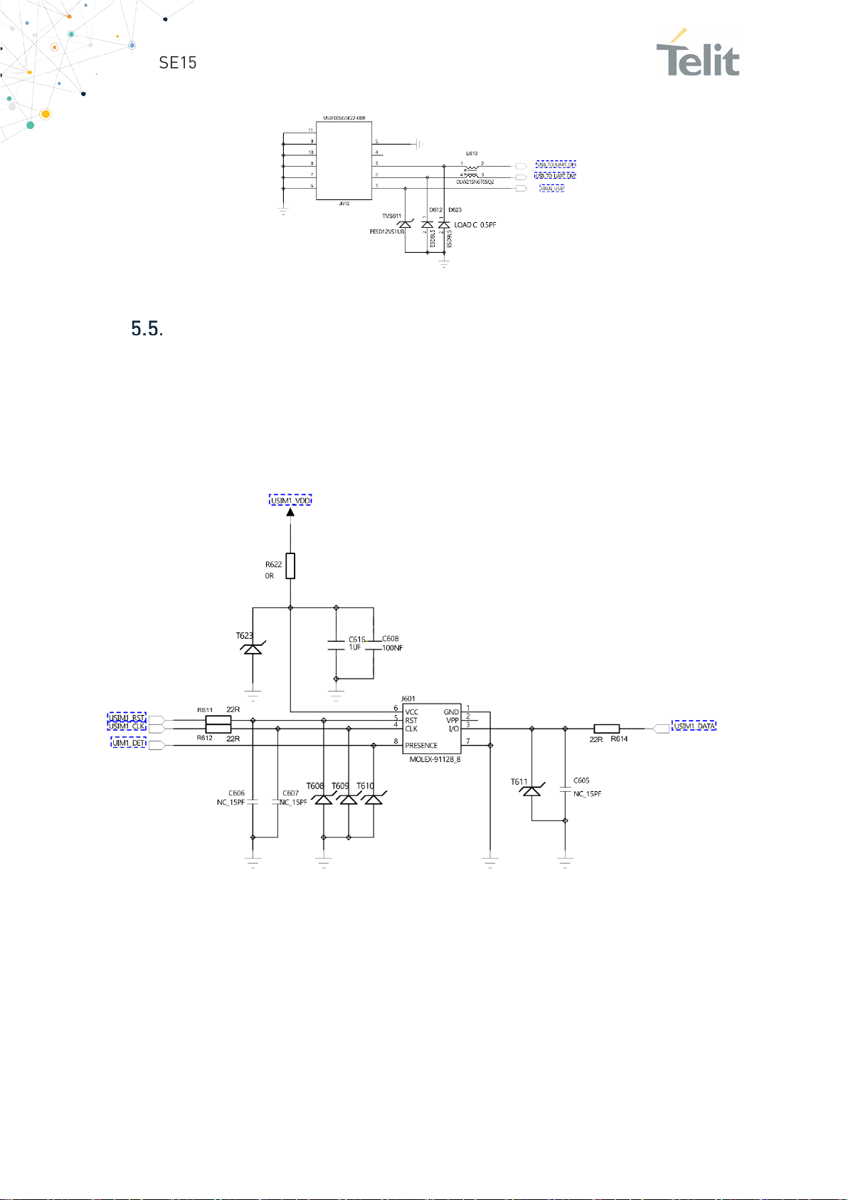
The EVB has two SIM Holders both support SIM presence pin usable for the Hot Swap
function).
USIM1 is available on J601, USIM2 on J602 card slot.
The following schematic is showing the connections:
1VV0301694 Rev. 1 Page 22 of 44 2021-01-29
Page 23
SE150A4 Smart Module EVB User Guide
SD CARD
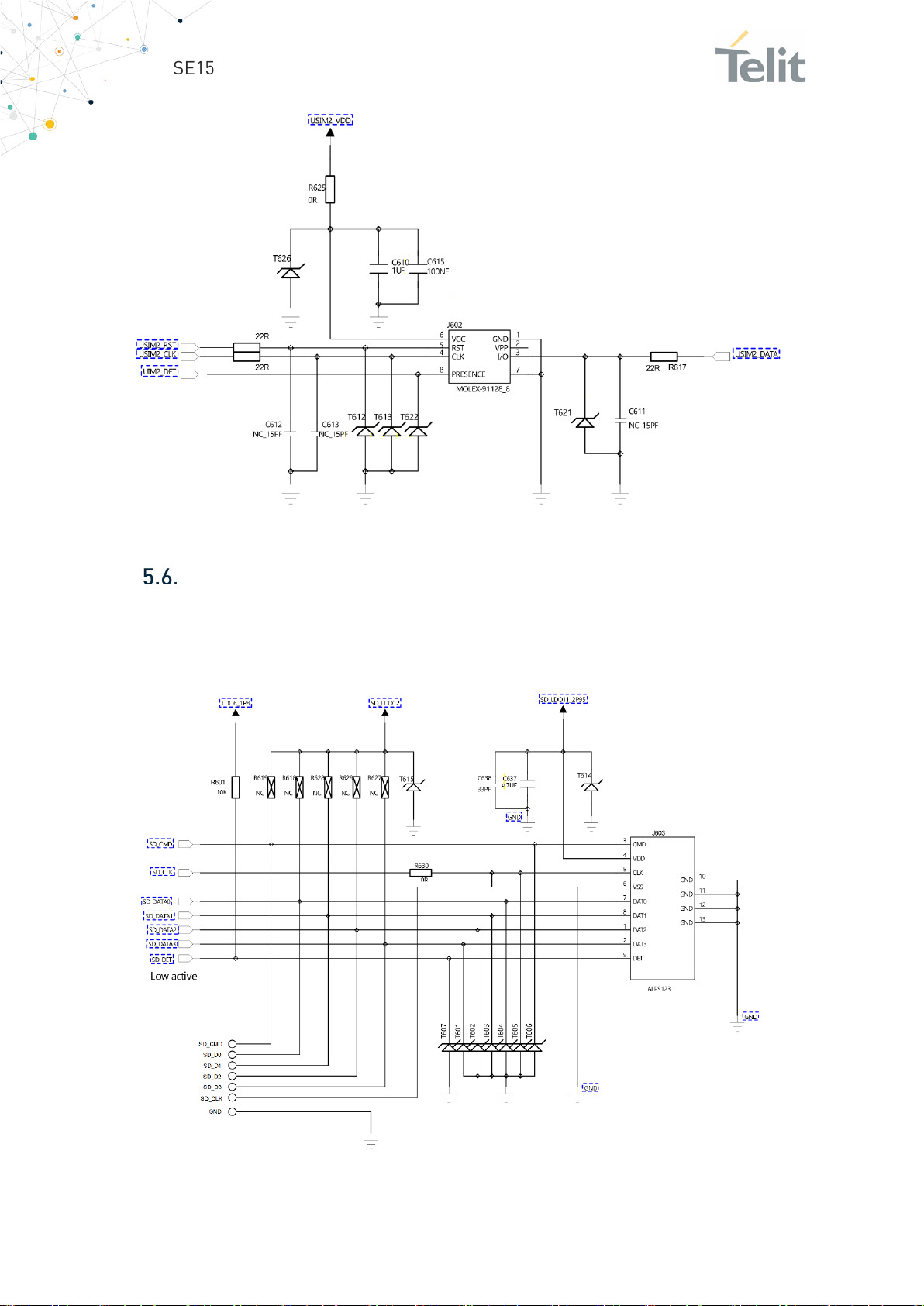
The SE150A4 Smart Module EVB is provided by one Mini SD Card holder (J603) has hot
swap function.
SD card circuit is shown below.
1VV0301694 Rev. 1 Page 23 of 44 2021-01-29
Page 24
SE150A4 Smart Module EVB User Guide
Control buttons
The SE150A4 Smart Module EVB has four buttons .These buttons functions are detailed
in the below sub sections.
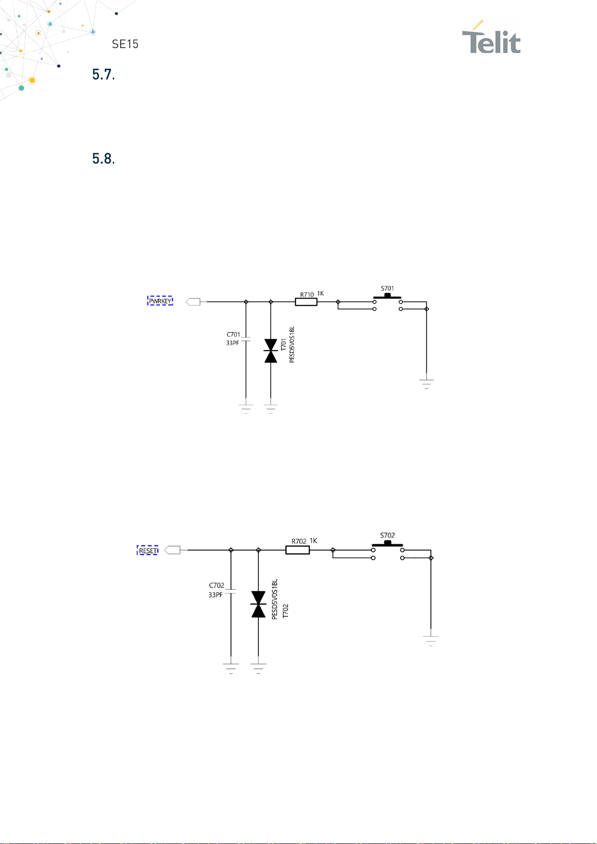
POWER Key
Used to power on and off the SE150A4 Smart Module. When the power supplied to EVB,
press the POWER Key for few seconds until the display shows the boot image (Telit Logo)
and then release it. Please refer the HW Design guide of SE150A4 Smart Module for the
detailed timings.
POWER Key circuit is shown below:
5.8.1. RESET Key
Used to run an unconditional restart of the SE150A4 Smart Module. Please refer the HW
Design guide of SE150A4 Smart Module for the detailed timings.
RESET Key circuit is shown below:
1VV0301694 Rev. 1 Page 24 of 44 2021-01-29
Page 25
SE150A4 Smart Module EVB User Guide
PWRKEY
VOL+
VOL-
Description
Key combination before
Power Up
Y Y Y Enter
Y N Y Enter engineering mode
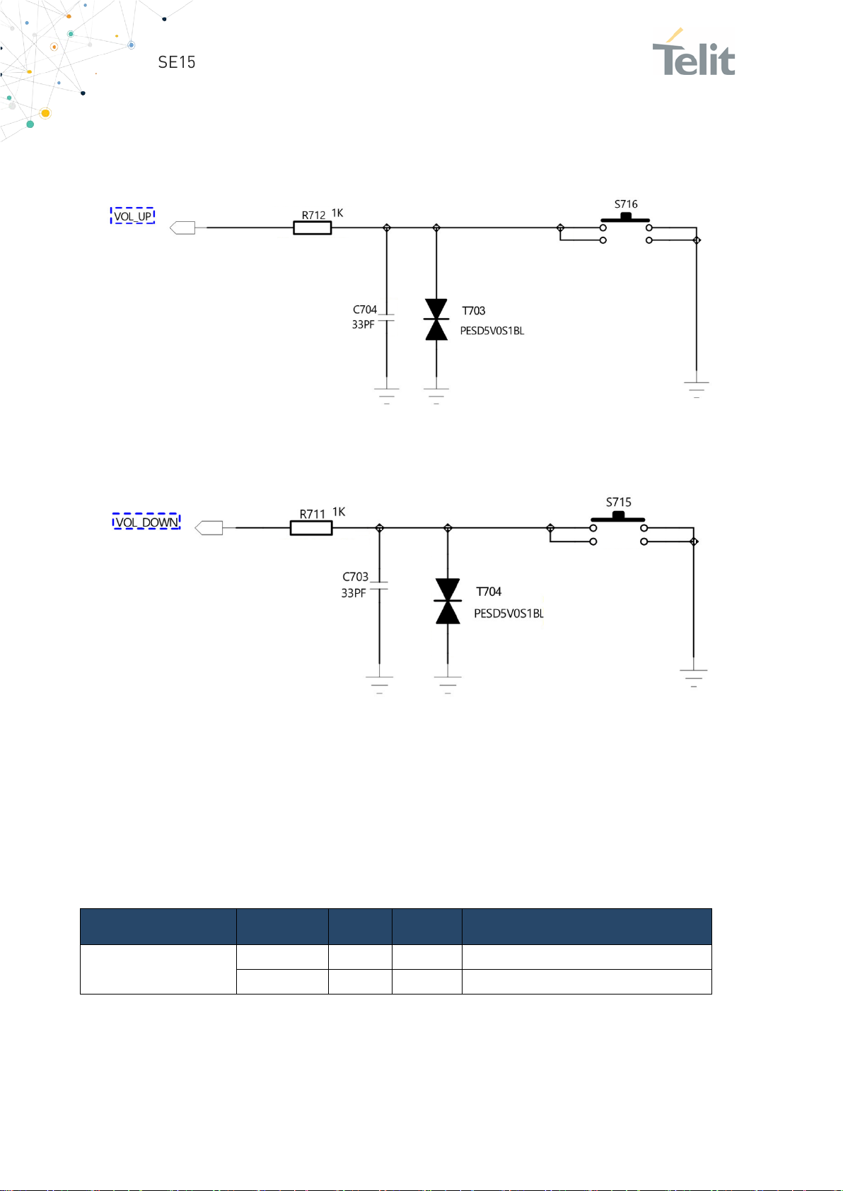
5.8.2. VOLUME Keys
Used to control the Audio Volume of the SE150A4 Smart Module.
VOLUME UP Key circuit is shown below:
And the VOLUME DOWN Key circuit is shown below.
5.8.3. Keys Combinations
The system also supports additional functions when pushing a combination of keys.
Pressing PWRKEY together with VOL + / VOL- allows to set the SE150A4 Smart Module
in USB Force boot or Engineering mode.
Key combination details are shown in the below table:
forced download mode
To start in normal mode, connect the power supply to EVB, press the power button until
the screen displays; then release the button.
1VV0301694 Rev. 1 Page 25 of 44 2021-01-29
Page 26
SE150A4 Smart Module EVB User Guide
Item
Value
Digital resolution
12 bit
Resolution (in ±2g range)
0.98 mg
Measurement ranges (programmable)
±2 g, ±4 g, ±8 g, ±16 g
Zero-g offset (typ., over life-time)
±100 mg
Noise density (typ.)
300 µg/vHz
Bandwidths (programmable)
1600 Hz ... 1.5 Hz
Supply voltage (VDD)
1.62 … 3.6 V
I/0 supply voltage (VDDIO)
1.2 … 3.6 V
FIFO data buffer
1 kB
Control
I2C
I2C Address
0x18
Sensors
The SE150A4 Smart Module EVB has two sensors (Accelerometer and Proximity)
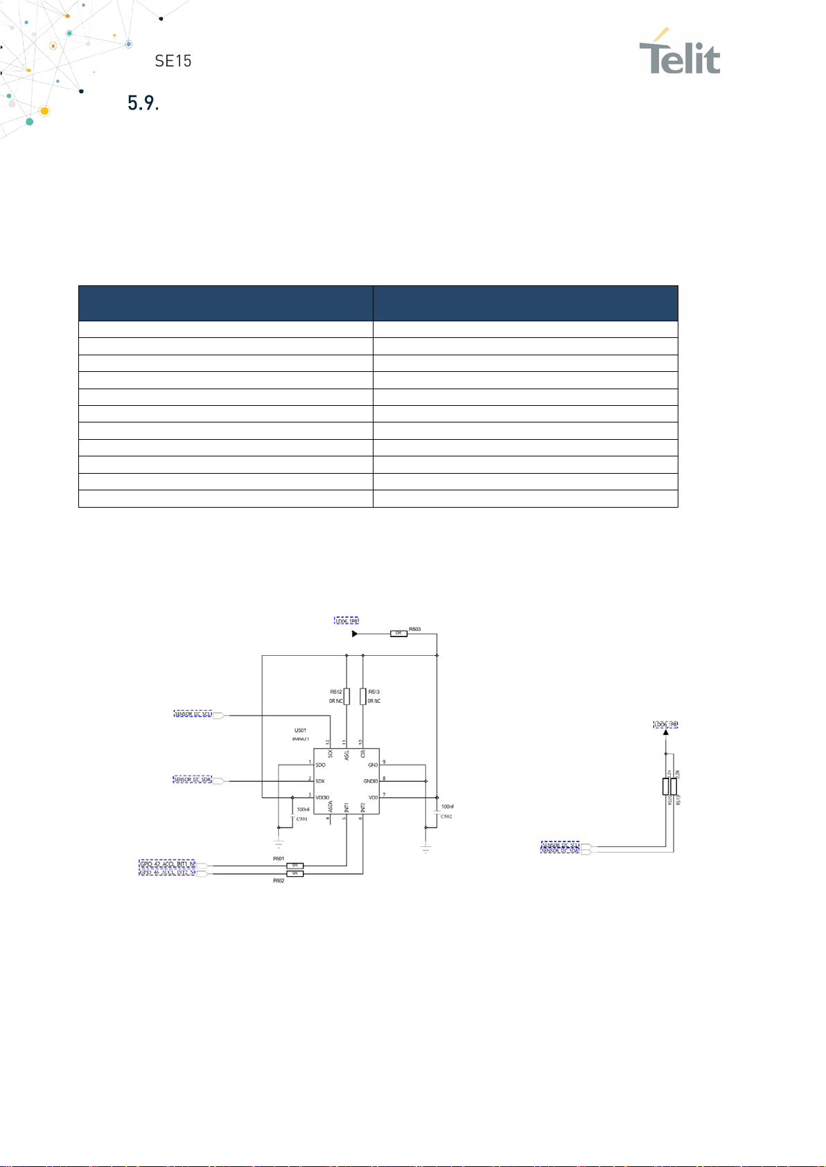
5.9.1. Accelerometer
Tri-axial low-g acceleration sensor from Bosch (BMA421) is used in the EVB.
The table below has details of the sensor:
Additional details on the component could be found in the component’s datasheet (ref.
to supplier website).
BMA421 sensor circuit is shown below:
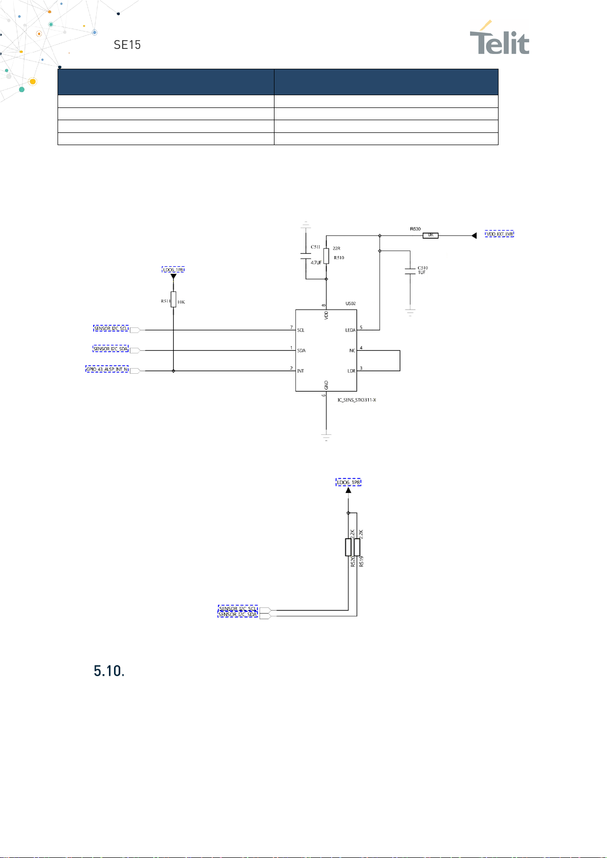
5.9.2. Proximity
The Proximity sensor is used to detect approaching objects. The EVB has Proximity (PS)
and Ambient Ligth (ALS) sensor from Sensortek STK3311-X.
The table below has the details of the sensor:
1VV0301694 Rev. 1 Page 26 of 44 2021-01-29
Page 27
SE150A4 Smart Module EVB User Guide
Item
Value
PS Digital resolution
16 bit
ALS Digital resolution
16 bit
Control
I2C
I2C Address
0x48
Additional details on the component could be found in the component’s datasheet (ref.
to supplier website).
STK3311-X sensor circuit is shown below:
Audio
The SE150A4 Smart Module EVB has the necessary circuit for all the Audio Interfaces.
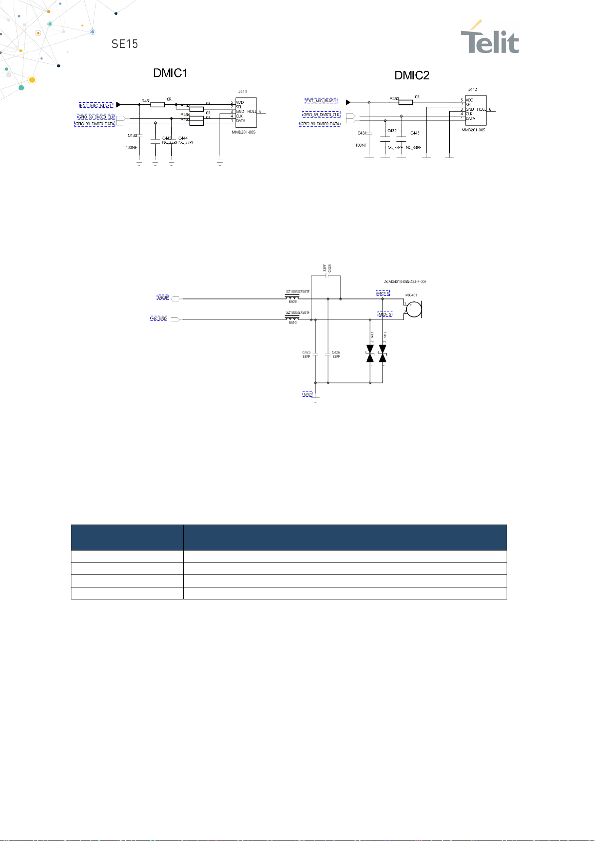
5.10.1. Digital Microphone
Two Digital microphones are available on the EVB. The related schematic is the
following:
1VV0301694 Rev. 1 Page 27 of 44 2021-01-29
Page 28
SE150A4 Smart Module EVB User Guide
Pin
Signal
1
MIC GND
2
EAR N
3
EAR P
4
MIC1 P
5.10.2. De-Noising Microphone
The Noise cancellation is performed using an additional microphone. This is the related
circuit on EVB:
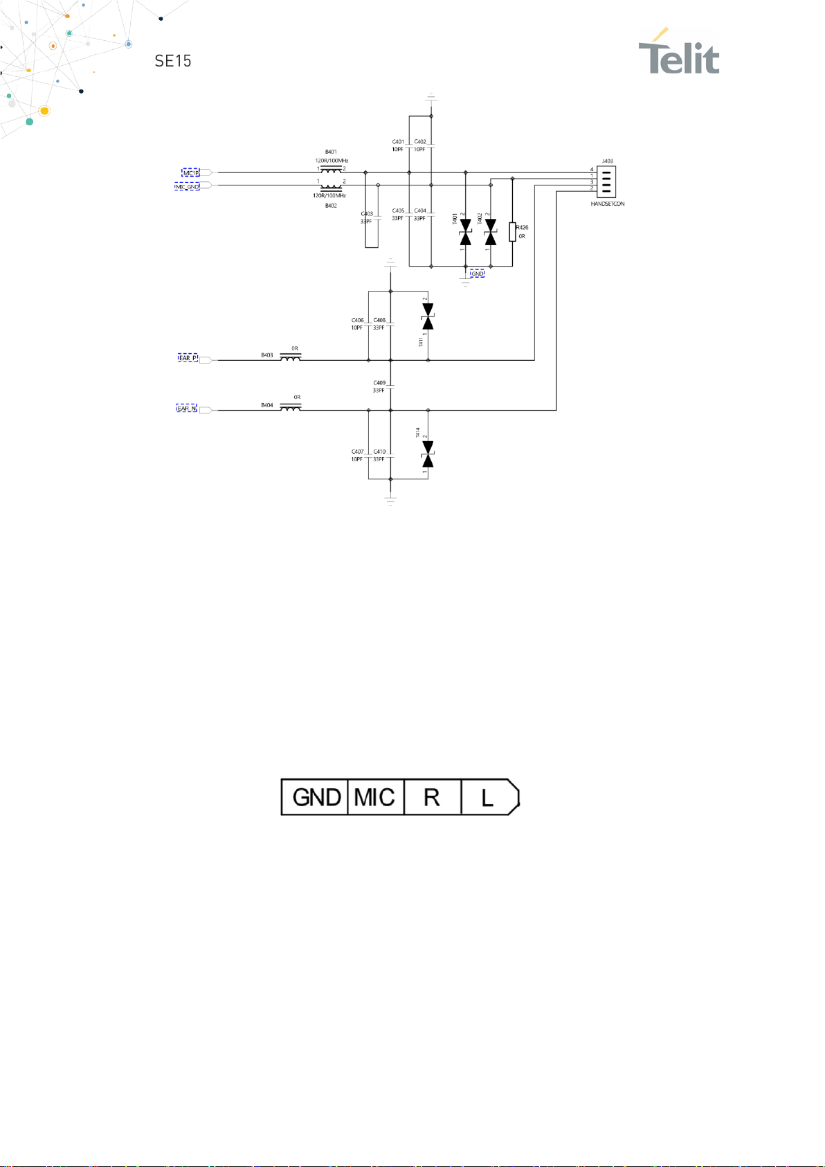
5.10.3. Handset
The Handset lines are available on an RJ11 connector (J403). The handset is often used
for audio test.
The pinout is shown in the table below.:
This is the related circuit on EVB:
1VV0301694 Rev. 1 Page 28 of 44 2021-01-29
Page 29
SE150A4 Smart Module EVB User Guide
In the hands-free mode, the MIC used is the handset MIC, and the speaker is switched to
the one present on EVB.
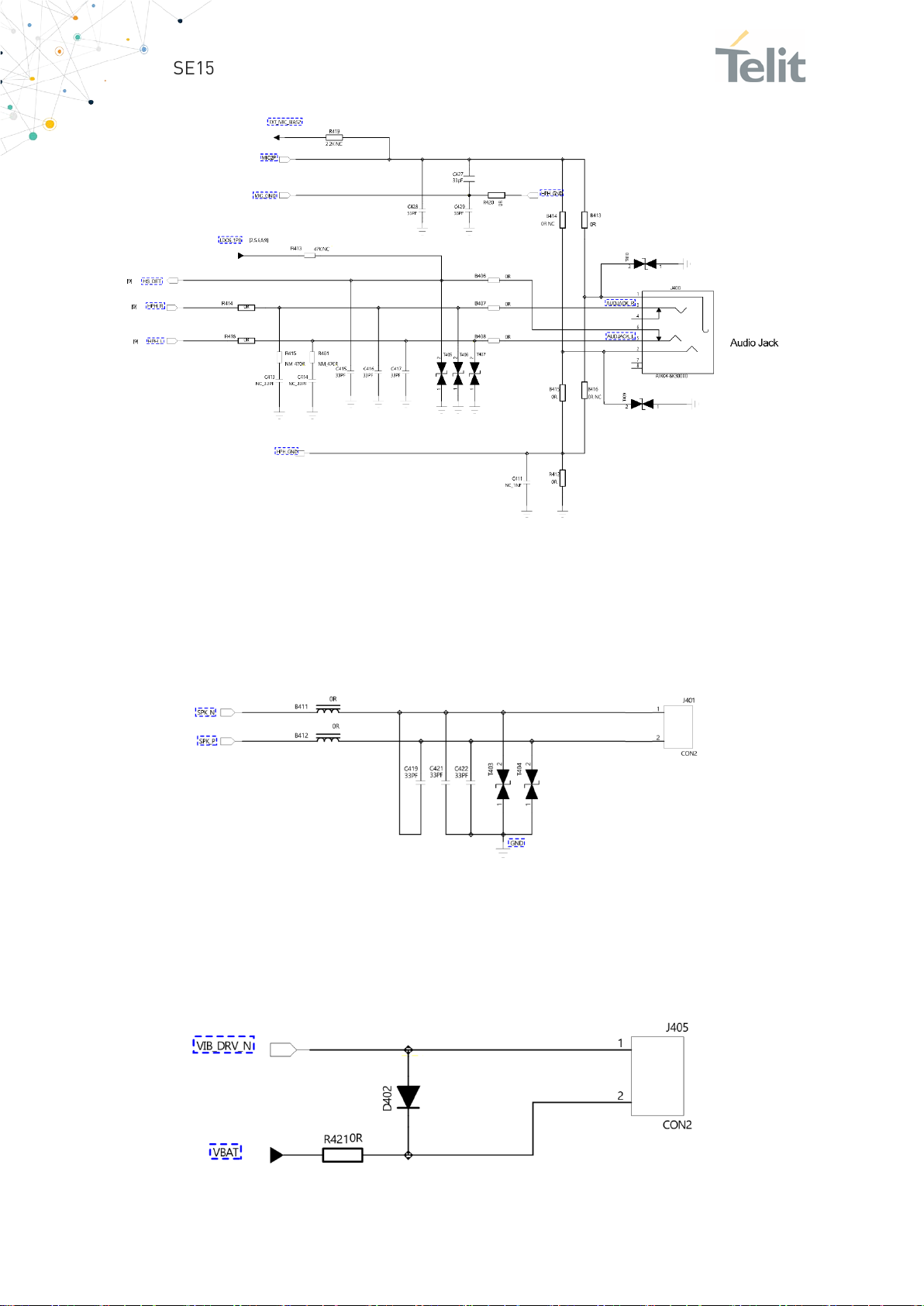
5.10.4. Headset
EVB has 3.5mm audio jack (J404), supports earphones having detection pins HS_DET and
HPH_L (detection circuit). There is a pull-down resistor inside HPH_L, when headphones
are not inserted, HS_DET and HPH_L are connected (status is LOW). When headphones
are inserted, HS_DET and HPH_L are disconnected (status HIGH).
Headset jack pinout is the following:
When the headset is inserted, there will be an interrupt to the SE150A4 Smart Module.
Audio lines will be switched to headset mode..
This is the related circuit on EVB:
1VV0301694 Rev. 1 Page 29 of 44 2021-01-29
Page 30
SE150A4 Smart Module EVB User Guide
5.10.5. Speaker
EVB has speaker for handsfree mode. It's circuit is shown below.
Its circuit on EVB is the following:
5.10.6. Vibrator
EVB has a Vibrator connected to J405
Its circuit is shown below:
1VV0301694 Rev. 1 Page 30 of 44 2021-01-29
Page 31
SE150A4 Smart Module EVB User Guide
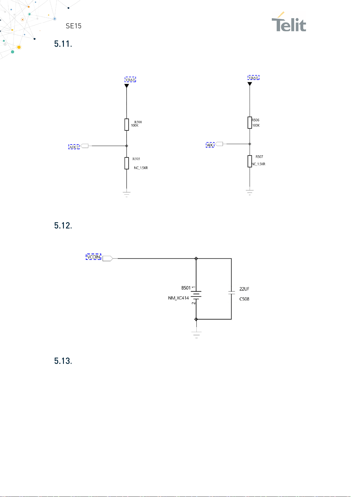
ADC
The two ADC are connected to VBAT through a voltage divider. The circuit is the following:
VCOIN
A backup battery for RTC could be connected to the module. This is the schematic:
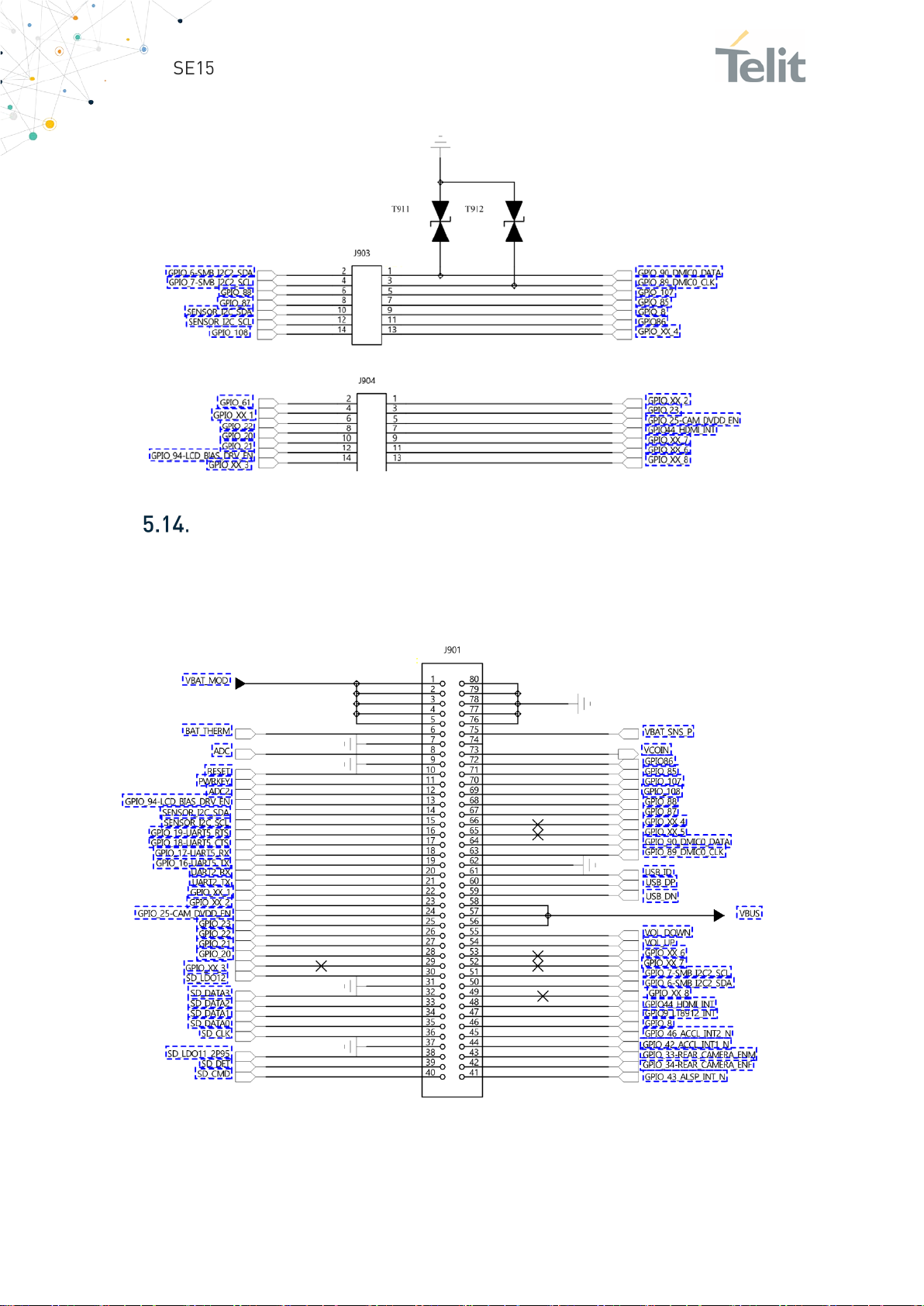
GPIO
A set of GPIOs are available on two connectors named J903 and J904.
1VV0301694 Rev. 1 Page 31 of 44 2021-01-29
Page 32
SE150A4 Smart Module EVB User Guide
The related schematic is shown below:
Board to Board Connectors
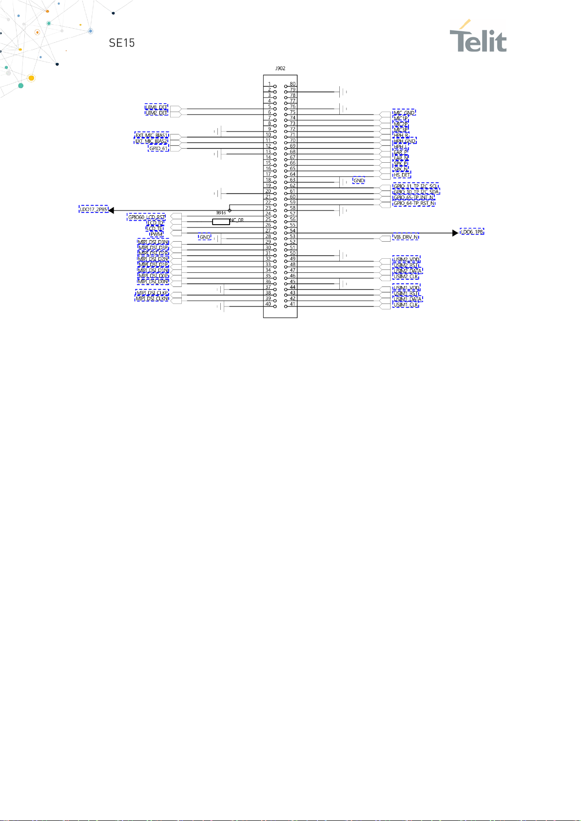
The Module’s Interface can be connected to the EVB through two socket connectors from
Panasonic with p/n AXK580147YG (80 PIN 0.5mm pitch 3.0mm height).
Schematic and Pinout is as shown in the connectors J901 and J902:
1VV0301694 Rev. 1 Page 32 of 44 2021-01-29
Page 33
SE150A4 Smart Module EVB User Guide
1VV0301694 Rev. 1 Page 33 of 44 2021-01-29
Page 34
SE150A4 Smart Module EVB User Guide
6. SE150A4 SMART MODULE INTERFACE
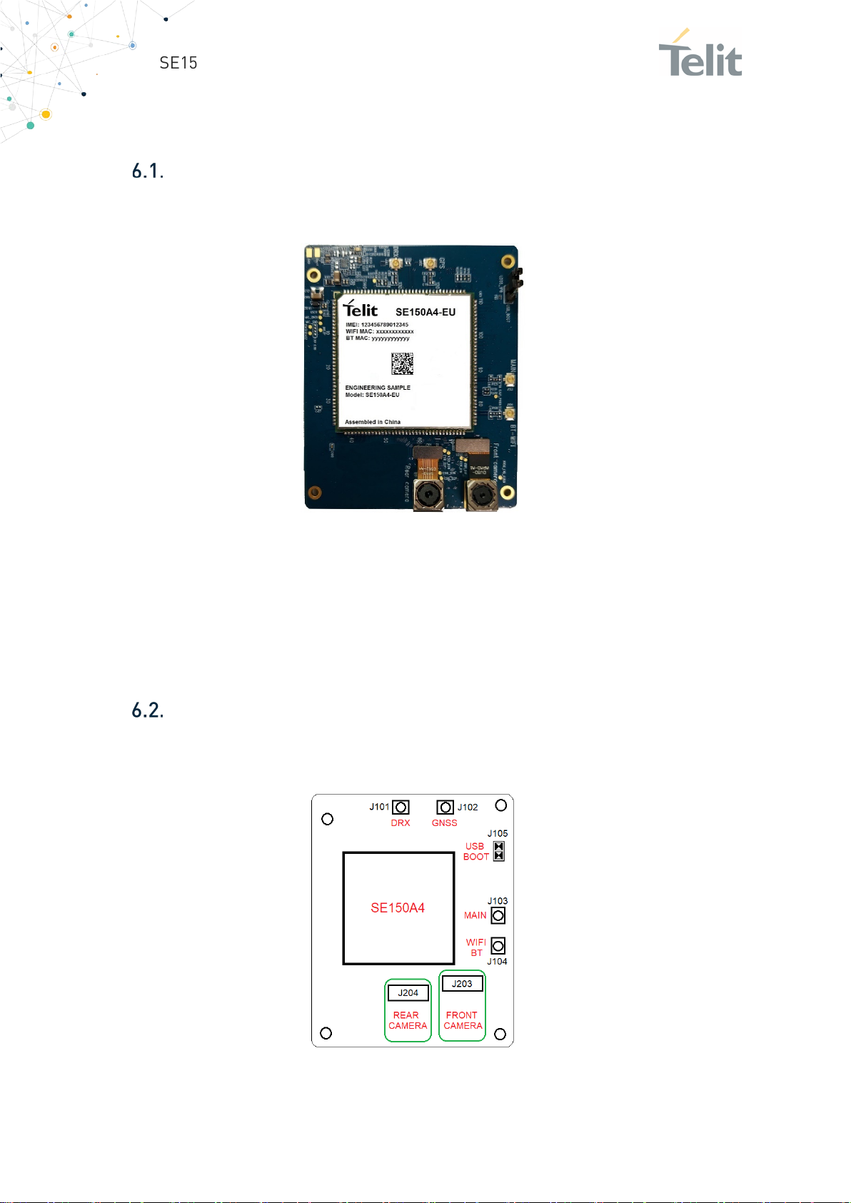
Description
For using SE150A4 Smart Module with EVB, Module is assembled on an interface board
which is shown below.:
The SE150A4 Smart Module Interface could be connected to the EVB through two header
connectors from Panasonic with p/n AXK680347YG (80 PIN 0.5mm pitch 3.0mm height)
that are assembled on bottom side of the PCB. The connectors are named J901 and J902.
The interface board also has all the RF connectors, a Jumper for the Low level USB
BOOT, and two Cameras.
Main Connectors and Devices Layout
The following Image is showing the position of the main connectors/devices on the
SE150A4 Smart Module Interface:
1VV0301694 Rev. 1 Page 34 of 44 2021-01-29
Page 35
SE150A4 Smart Module EVB User Guide
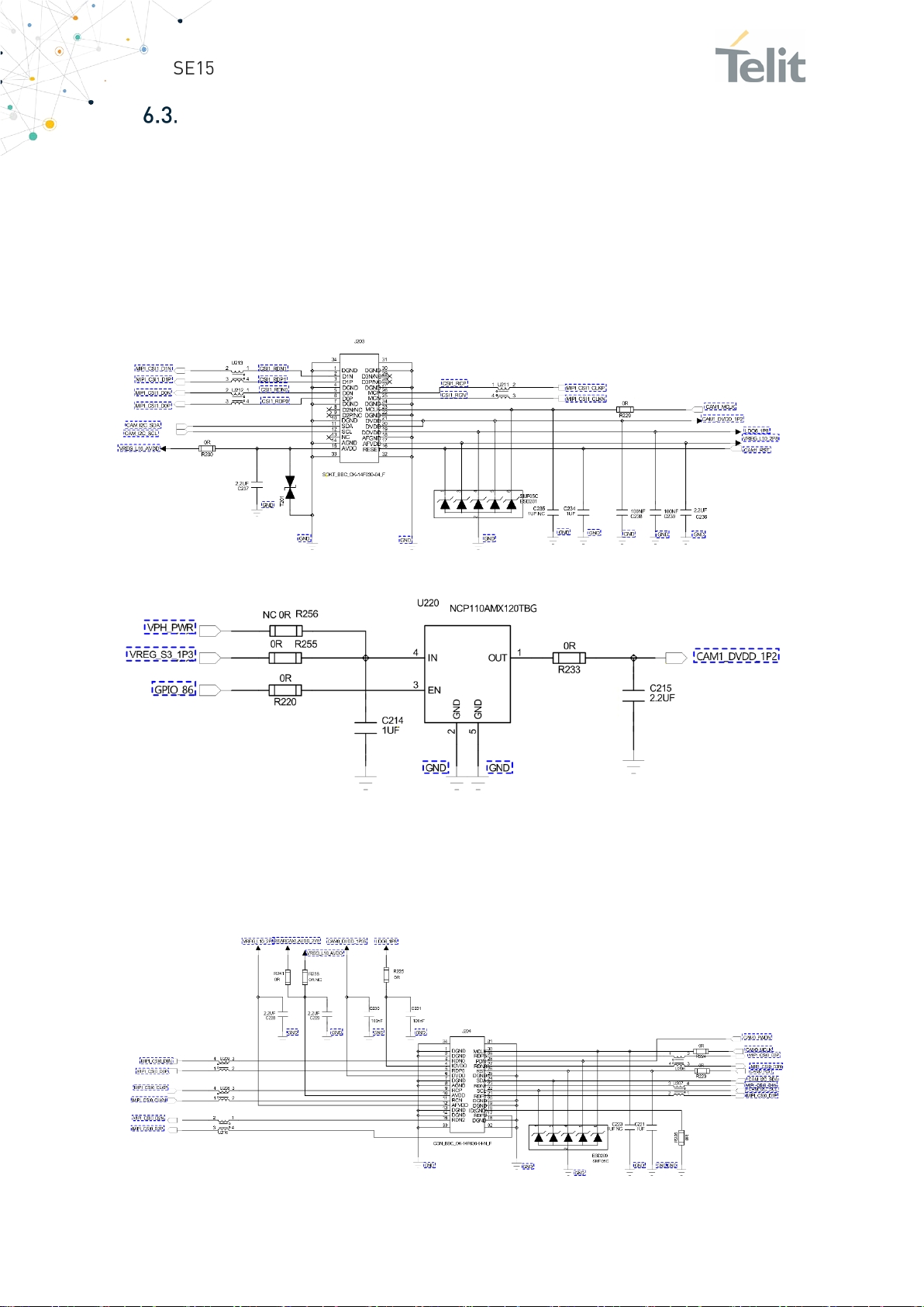
Camera
The SE150A4 Smart Module is supporting two Cameras (Front and Rear). Both are
assembled on the module’s Interface board and the interface is I2C.
6.3.1. Front Camera
The Front camera is a 13M pixel using an FP5510A IC with I2C address 0x20. This is the
related circuit:
The supply section is the following:
6.3.2. Rear Camera
The Rear camera is with 5M pixel and it is using the PE918 IC with I2C address 0x5A. This
is the related circuit:
1VV0301694 Rev. 1 Page 35 of 44 2021-01-29
Page 36
SE150A4 Smart Module EVB User Guide
Note/Tip: We recommended the Passive antenna for GNSS
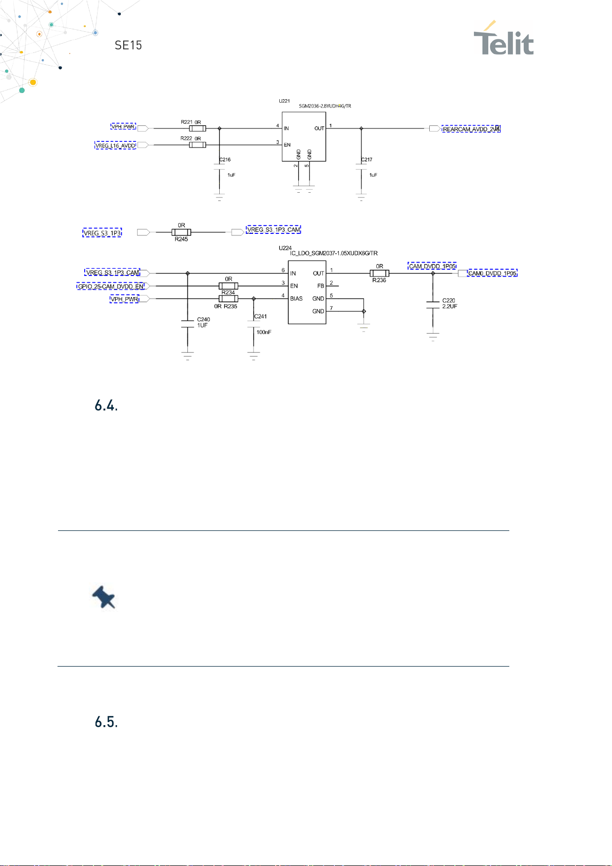
The supply section is the following:
RF Connectors
The Interface board has four U.FL-R-SMT-1(80) for connecting Antennas.
EVB kit contains 3 small RF cables (uFL to SMA female) for connecting antennas provided
in the kit.
To use antennas other than provided in the kit, refer to the module HW Design Guide for
the antenna specifications.
because the SE150A4 already includes 20dB LNA.
If Active antenna should be used, it requires additional circuit to
supply power to the antenna and also a capacitor in series to
the module to block the DC.
Please refer to the module’s HW design Guide for the details.
USB BOOT
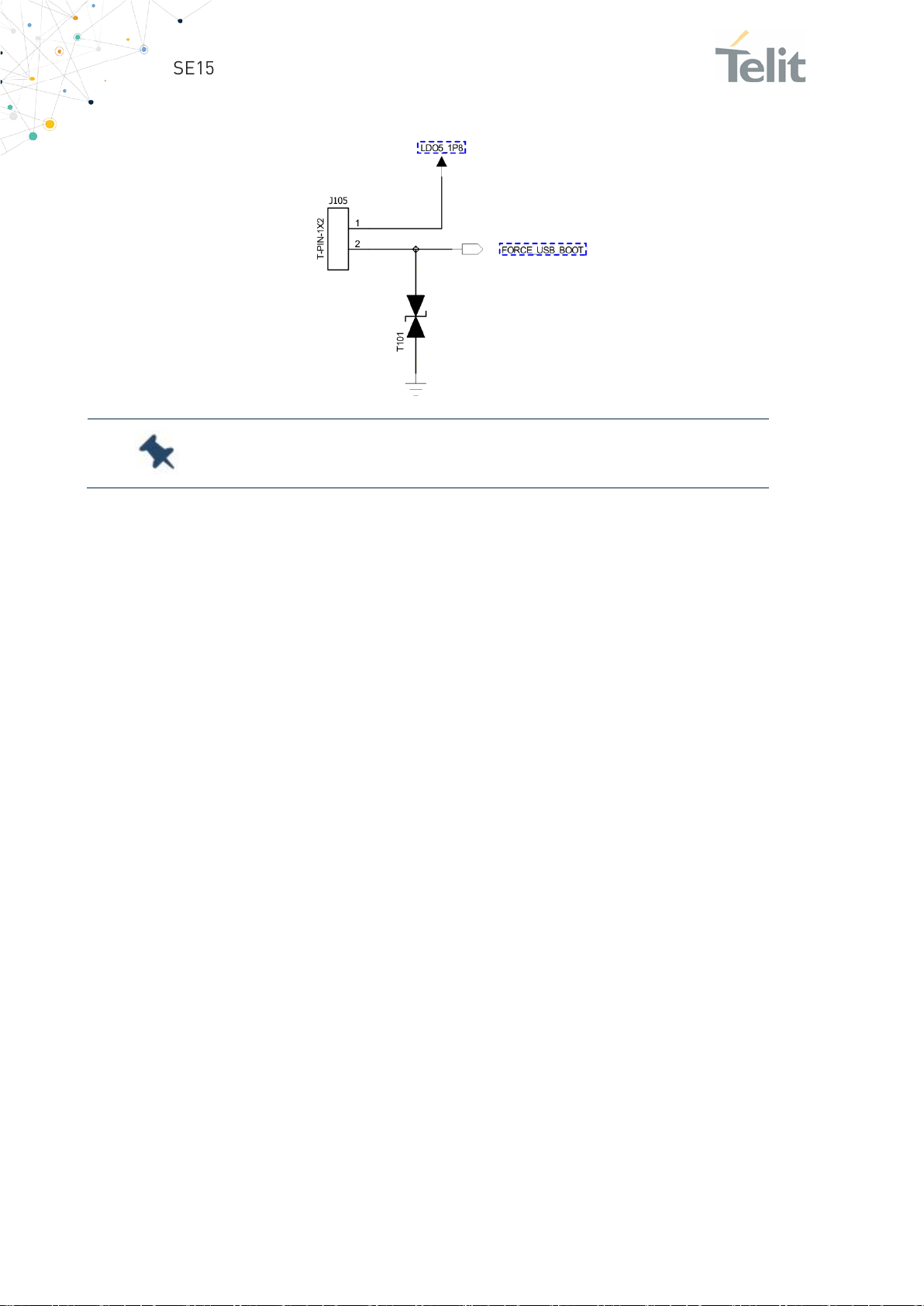
The interface board has a two pin connector (J105) to place the SE150A4 into the USB
BOOT mode. For this, connect a jumper on J105.
The FORCE USB BOOT signal is active high.
1VV0301694 Rev. 1 Page 36 of 44 2021-01-29
Page 37
SE150A4 Smart Module EVB User Guide
Note/Tip:
By default the jumper is not mounted on J105.
1VV0301694 Rev. 1 Page 37 of 44 2021-01-29
Page 38

SE150A4 Smart Module EVB User Guide
7. PRODUCT AND SAFETY INFORMATION
Copyrights and Other Notices
SPECIFICATIONS ARE SUBJECT TO CHANGE WITHOUT NOTICE
Although reasonable efforts have been made to ensure the accuracy of this document,
Telit assumes no liability resulting from any inaccuracies or omissions in this document,
or from the use of the information contained herein. The information in this document
has been carefully checked and is believed to be reliable. Telit reserves the right to make
changes to any of the products described herein, to revise it and to make changes from
time to time with no obligation to notify anyone of such revisions or changes. Telit does
not assume any liability arising from the application or use of any product, software, or
circuit described herein; neither does it convey license under its patent rights or the
rights of others.
This document may contain references or information about Telit’s products (machines
and programs), or services that are not announced in your country. Such references or
information do not necessarily mean that Telit intends to announce such Telit products,
programming, or services in your country.
7.1.1. Copyrights
This instruction manual and the Telit products described herein may include or describe
Telit’s copyrighted material, such as computer programs stored in semiconductor
memories or other media. Laws in Italy and in other countries reserve to Telit and its
licensors certain exclusive rights for copyrighted material, including the exclusive righ
to copy, reproduce in any form, distribute and make derivative works of the copyrighted
material. Accordingly, any of Telit’s or its licensors’ copyrighted material contained
herein or described in this instruction manual, shall not be copied, reproduced,
distributed, merged or modified in any manner without the express written permission
of the owner. Furthermore, the purchase of Telit’s products shall not be deemed to grant
in any way, neither directly nor by implication, or estoppel, any license.
7.1.2. Computer Software Copyrights
Telit and the 3rd Party supplied Software (SW) products, described in this instruction
manual may include Telit’s and other 3rd Party’s copyrighted computer programs stored
in semiconductor memories or other media. Laws in Italy and in other countries reserve
to Telit and other 3rd Party SW exclusive rights for copyrighted computer programs,
including – but not limited to - the exclusive right to copy or reproduce in any form the
1VV0301694 Rev. 1 Page 38 of 44 2021-01-29
Page 39

SE150A4 Smart Module EVB User Guide
copyrighted products. Accordingly, any copyrighted computer programs contained in
Telit’s products described in this instruction manual shall not be copied (reverse
engineered) or reproduced in any manner without the express written permission of the
copyright owner, being Telit or the 3rd Party software supplier. Furthermore, the
purchase of Telit products shall not be deemed to grant either directly or by implication,
estoppel, or in any other way, any license under the copyrights, patents or patent
applications of Telit or other 3rd Party supplied SW, except for the normal non-exclusive,
royalty free license to use arising by operation of law in the sale of a product.
Usage and Disclosure Restrictions
7.2.1. License Agreements
The software described in this document is owned by Telit and its licensors. It is
furnished by express license agreement only and shall be used exclusively in accordance
with the terms of such agreement.
7.2.2. Copyrighted Materials
The Software and the documentation are copyrighted materials. Making unauthorized
copies is prohibited by the law. The software or the documentation shall not be
reproduced, transmitted, transcribed, even partially, nor stored in a retrieval system, nor
translated into any language or computer language, in any form or by any means, without
prior written permission of Telit.
7.2.3. High Risk Materials
Components, units, or third-party goods used in the making of the product described
herein are NOT fault-tolerant and are NOT designed, manufactured, or intended for use
as on-line control equipment in the following hazardous environments requiring fail-safe
controls: operations of Nuclear Facilities, Aircraft Navigation or Aircraft Communication
Systems, Air Traffic Control, Life Support, or Weapons Systems (“High Risk Activities").
Telit and its supplier(s) specifically disclaim any expressed or implied warranty of fitness
eligibility for such High Risk Activities.
7.2.4. Trademarks
TELIT and the Stylized T-Logo are registered in the Trademark Office. All other product
or service names are property of their respective owners.
1VV0301694 Rev. 1 Page 39 of 44 2021-01-29
Page 40

SE150A4 Smart Module EVB User Guide
7.2.5. Third Party Rights
The software may include 3rd Party’s software Rights. In this case the user agrees to
comply with all terms and conditions imposed in respect of such separate software
rights. In addition to 3rd Party Terms, the disclaimer of warranty and limitation of liability
provisions in this License, shall apply to the 3rd Party Rights software as well.
TELIT HEREBY DISCLAIMS ANY AND ALL WARRANTIES EXPRESSED OR IMPLIED FROM
ANY 3RD PARTY REGARDING ANY SEPARATE FILES, ANY 3RD PARTY MATERIALS
INCLUDED IN THE SOFTWARE, ANY 3RD PARTY MATERIALS FROM WHICH THE
SOFTWARE IS DERIVED (COLLECTIVELY “OTHER CODES”), AND THE USE OF ANY OR
ALL OTHER CODES IN CONNECTION WITH THE SOFTWARE, INCLUDING (WITHOUT
LIMITATION) ANY WARRANTIES OF SATISFACTORY QUALITY OR FITNESS FOR A
PARTICULAR PURPOSE.
NO 3RD PARTY LICENSORS OF OTHER CODES MUST BE LIABLE FOR ANY DIRECT,
INDIRECT, INCIDENTAL, SPECIAL, EXEMPLARY, OR CONSEQUENTIAL DAMAGES
(INCLUDING WITHOUT LIMITATION LOST OF PROFITS), HOWEVER CAUSED AND
WHETHER MADE UNDER CONTRACT, TORT OR OTHER LEGAL THEORY, ARISING IN ANY
WAY OUT OF THE USE OR DISTRIBUTION OF THE OTHER CODES OR THE EXERCISE OF
ANY RIGHTS GRANTED UNDER EITHER OR BOTH THIS LICENSE AND THE LEGAL
TERMS APPLICABLE TO ANY SEPARATE FILES, EVEN IF ADVISED OF THE POSSIBILITY
OF SUCH DAMAGES.
7.2.6. Waiwer of Liability
IN NO EVENT WILL TELIT AND ITS AFFILIATES BE LIABLE FOR AY DIRECT, INDIRECT,
SPECIAL, GENERAL, INCIDENTAL, CONSEQUENTIAL, PUNITIVE OR EXEMPLARY
INDIRECT DAMAGE OF ANY KIND WHATSOEVER, INCLUDING BUT NOT LIMITED TO
REIMBURSEMENT OF COSTS, COMPENSATION OF ANY DAMAGE, LOSS OF
PRODUCTION, LOSS OF PROFIT, LOSS OF USE, LOSS OF BUSINESS, LOSS OF DATA OR
REVENUE, WHETHER OR NOT THE POSSIBILITY OF SUCH DAMAGES COULD HAVE
BEEN REASONABLY FORESEEN, CONNECTD IN ANY WAY TO THE USE OF THE
PRODUCT/S OR TO THE INFORMATION CONTAINED IN THE PRESENT
DOCUMENTATION, EVEN IF TELIT AND/OR ITS AFFILIATES HAVE BEEN ADVISED OF
THE POSSIBILITY OF SUCH DAMAGES OR THEY ARE FORESEEABLE OR FOR CLAIMS BY
ANY THIRD PARTY.
Safety Recommendations
Make sure the use of this product is allowed in your country and in the environment
required. The use of this product may be dangerous and has to be avoided in areas where:
1VV0301694 Rev. 1 Page 40 of 44 2021-01-29
Page 41

SE150A4 Smart Module EVB User Guide
• it can interfere with other electronic devices, particularly in environments such as
hospitals, airports, aircrafts, etc.
• there is a risk of explosion such as gasoline stations, oil refineries, etc. It is the
responsibility of the user to enforce the country regulation and the specific
environment regulation.
Do not disassemble the product; any mark of tampering will compromise the warranty
validity. We recommend following the instructions of the hardware user guides for
correct wiring of the product. The product has to be supplied with a stabilized voltage
source and the wiring has to be conformed to the security and fire prevention
regulations. The product has to be handled with care, avoiding any contact with the pins
because electrostatic discharges may damage the product itself. Same cautions have to
be taken for the SIM, checking carefully the instruction for its use. Do not insert or
remove the SIM when the product is in power saving mode.
The system integrator is responsible for the functioning of the final product. Therefore,
the external components of the module, as well as any project or installation issue, have
to be handled with care. Any interference may cause the risk of disturbing the GSM
network or external devices or having an impact on the security system. Should there be
any doubt, please refer to the technical documentation and the regulations in force. Every
module has to be equipped with a proper antenna with specific characteristics. The
antenna has to be installed carefully in order to avoid any interference with other
electronic devices and has to guarantee a minimum distance from the body (20 cm). In
case this requirement cannot be satisfied, the system integrator has to assess the final
product against the SAR regulation.
The equipment is intended to be installed in a restricted area location.
The equipment must be supplied by an external specific limited power source in
compliance with the standard EN 62368-1:2014.
The European Community provides some Directives for the electronic equipment
introduced on the market. All of the relevant information is available on the European
Community website:
https://ec.europa.eu/growth/sectors/electrical-engineering_en
1VV0301694 Rev. 1 Page 41 of 44 2021-01-29
Page 42

SE150A4 Smart Module EVB User Guide
TTSC
USB
HS
DTE
UMTS
WCDMA
HSDPA
HSUPA
UART
HSIC
SIM
SPI
ADC
DAC
I/O
GPIO
CMOS
MOSI
MISO
CLK
MRDY
SRDY
CS
RTC
PCB
ESR
VSWR
VNA
8. ACRONYMS
Telit Technical Support Centre
Universal Serial Bus
High Speed
Data Terminal Equipment
Universal Mobile Telecommunication System
Wideband Code Division Multiple Access
High Speed Downlink Packet Access
High Speed Uplink Packet Access
Universal Asynchronous Receiver Transmitter
High Speed Inter Chip
Subscriber Identification Module
Serial Peripheral Interface
Analog – Digital Converter
Digital – Analog Converter
Input Output
General Purpose Input Output
Complementary Metal – Oxide Semiconductor
Master Output – Slave Input
Master Input – Slave Output
Clock
Master Ready
Slave Ready
Chip Select
Real Time Clock
Printed Circuit Board
Equivalent Series Resistance
Voltage Standing Wave Radio
Vector Network Analyzer
1VV0301694 Rev. 1 Page 42 of 44 2021-01-29
Page 43

SE150A4 Smart Module EVB User Guide
Revision
Date
Changes
1
0
9. DOCUMENT HISTORY
2021-21-01 Figure updates
2.2 Content of the Kit
3. Functional Description
3.2 Main Connectors and Devices Layout
3.3 Switch and Jumpers Settings
6. SE150A4 Smart Module Interface
2020-11-11 First issue
1VV0301694 Rev. 1 Page 43 of 44 2021-01-29
Page 44

Mod.08
Telit Technical Documentation
18 2017-01 Rev.0
 Loading...