

Page 1

[
Software User Guide
LE910Cx
1VV0301556 Rev. 7 – 2020-09-25
1VV0301556 2019-09 Rev.3
09.2019]
Page 2

SPECIFICATIONS ARE SUBJECT TO CHANGE WITHOUT NOTICE
NOTICES LIST
While reasonable efforts have been made to assure the accuracy of this document, Telit assumes
no liability resulting from any inaccuracies or omissions in this document, or from use of the
information obtained herein. The information in this document has been carefully checked and is
believed to be reliable. However, no responsibility is assumed for inaccuracies or omissions. Telit
reserves the right to make changes to any products described herein and reserves the right to
revise this document and to make changes from time to time in content hereof with no obligation
to notify any person of revisions or changes. Telit does not assume any liability arising out of the
application or use of any product, software, or circuit described herein; neither does it convey
license under its patent rights or the rights of others.
It is possible that this publication may contain references to, or information about Telit products
(machines and programs), programming, or services that are not announced in your country. Such
references or information must not be construed to mean that Telit intends to announce such Telit
products, programming, or services in your country.
COPYRIGHTS
This instruction manual and the Telit products described in this instruction manual may be, include
or describe copyrighted Telit material, such as computer programs stored in semiconductor
memories or other media. Laws in the Italy and other countries preserve for Telit and its licensors
certain exclusive rights for copyrighted material, including the exclusive right to copy, reproduce
in any form, distribute and make derivative works of the copyrighted material. Accordingly, any
copyrighted material of Telit and its licensors contained herein or in the Telit products described
in this instruction manual may not be copied, reproduced, distributed, merged or modified in any
manner without the express written permission of Telit. Furthermore, the purchase of Telit
products shall not be deemed to grant either directly or by implication, estoppel, or otherwise, any
license under the copyrights, patents or patent applications of Telit, as arises by operation of law
in the sale of a product.
COMPUTER SOFTWARE COPYRIGHTS
The Telit and 3rd Party supplied Software (SW) products described in this instruction manual may
include copyrighted Telit and other 3rd Party supplied computer programs stored in semiconductor
memories or other media. Laws in the Italy and other countries preserve for Telit and other 3rd
Party supplied SW certain exclusive rights for copyrighted computer programs, including the
exclusive right to copy or reproduce in any form the copyrighted computer program. Accordingly,
any copyrighted Telit or other 3rd Party supplied SW computer programs contained in the Telit
products described in this instruction manual may not be copied (reverse engineered) or
reproduced in any manner without the express written permission of Telit or the 3rd Party SW
supplier. Furthermore, the purchase of Telit products shall not be deemed to grant either directly
or by implication, estoppel, or otherwise, any license under the copyrights, patents or patent
applications of Telit or other 3rd Party supplied SW, except for the normal non-exclusive, royalty
free license to use that arises by operation of law in the sale of a product.
1VV0301556 Rev. 7
Page 2 of 145
2020-09-25
Page 3

USAGE AND DISCLOSURE RESTRICTIONS
I. License Agreements
The software described in this document is the property of Telit and its licensors. It is furnished by
express license agreement only and may be used only in accordance with the terms of such an
agreement.
II. Copyrighted Materials
Software and documentation are copyrighted materials. Making unauthorized copies is prohibited
by law. No part of the software or documentation may be reproduced, transmitted, transcribed,
stored in a retrieval system, or translated into any language or computer language, in any form or
by any means, without prior written permission of Telit
III. High Risk Materials
Components, units, or third-party products used in the product described herein are NOT faulttolerant and are NOT designed, manufactured, or intended for use as on-line control equipment
in the following hazardous environments requiring fail-safe controls: the operation of Nuclear
Facilities, Aircraft Navigation or Aircraft Communication Systems, Air Traffic Control, Life Support,
or Weapons Systems (High Risk Activities"). Telit and its supplier(s) specifically disclaim any
expressed or implied warranty of fitness for such High Risk Activities.
IV. Trademarks
TELIT and the Stylized T Logo are registered in Trademark Office. All other product or service
names are the property of their respective owners.
V. Third Party Rights
The software may include Third Party Right software. In this case you agree to comply with all
terms and conditions imposed on you in respect of such separate software. In addition to Third
Party Terms, the disclaimer of warranty and limitation of liability provisions in this License shall
apply to the Third Party Right software.
TELIT HEREBY DISCLAIMS ANY AND ALL WARRANTIES EXPRESS OR IMPLIED FROM ANY
THIRD PARTIES REGARDING ANY SEPARATE FILES, ANY THIRD PARTY MATERIALS
INCLUDED IN THE SOFTWARE, ANY THIRD PARTY MATERIALS FROM WHICH THE
SOFTWARE IS DERIVED (COLLECTIVELY “OTHER CODE”), AND THE USE OF ANY OR ALL
THE OTHER CODE IN CONNECTION WITH THE SOFTWARE, INCLUDING (WITHOUT
LIMITATION) ANY WARRANTIES OF SATISFACTORY QUALITY OR FITNESS FOR A
PARTICULAR PURPOSE.
NO THIRD PARTY LICENSORS OF OTHER CODE SHALL HAVE ANY LIABILITY FOR ANY
DIRECT, INDIRECT, INCIDENTAL, SPECIAL, EXEMPLARY, OR CONSEQUENTIAL DAMAGES
(INCLUDING WITHOUT LIMITATION LOST PROFITS), HOWEVER CAUSED AND WHETHER
MADE UNDER CONTRACT, TORT OR OTHER LEGAL THEORY, ARISING IN ANY WAY OUT
OF THE USE OR DISTRIBUTION OF THE OTHER CODE OR THE EXERCISE OF ANY RIGHTS
GRANTED UNDER EITHER OR BOTH THIS LICENSE AND THE LEGAL TERMS APPLICABLE
TO ANY SEPARATE FILES, EVEN IF ADVISED OF THE POSSIBILITY OF SUCH DAMAGES.
1VV0301556 Rev. 7
Page 3 of 145
2020-09-25
Page 4

APPLICABILITY TABLE
PRODUCTS
LE910C1-NA
LE910C1-NS
LE910CX-NF
LE910CX-EU
LE910CX-AP
LE910CX-LA
LE910CX-CN
LE910C1-SV
LE910C1-SA
LE910C1-ST
LE910C1-EUX
LE910C1-SAX
LE910C1-SVX
Table 1 Products
1VV0301556 Rev. 7
Page 4 of 145
2020-09-25
Page 5

CONTENTS
NOTICES LIST ............................................................................................... 2
COPYRIGHTS ................................................................................................ 2
COMPUTER SOFTWARE COPYRIGHTS ...................................................... 2
USAGE AND DISCLOSURE RESTRICTIONS ............................................... 3
APPLICABILITY TABLE ................................................................................ 4
CONTENTS .................................................................................................... 5
1. INTRODUCTION .......................................................................... 8
Scope ........................................................................................... 8
Audience....................................................................................... 8
Contact Information, Support ........................................................ 8
Text Conventions ........................................................................ 10
Related Documents .................................................................... 11
2. LE910CX VARIANTS ................................................................. 12
3. HIGH LEVEL SW ARCHITECTURE ........................................... 13
Architecture based on Linux ....................................................... 13
Architecture based on ThreadX .................................................. 14
4. FUNCTIONAL DESCRIPTION ................................................... 15
General Functionality and Main Features.................................... 15
Application system overview ....................................................... 15
4.2.1. Memory configuration ................................................................. 16
4.2.2. Partition Layout ........................................................................... 16
4.2.3. RAM memory .............................................................................. 20
4.2.4. Customer application – Storage & configuration ......................... 21
4.2.5. Power up time ............................................................................. 22
4.2.6. Power up sequence .................................................................... 22
4.2.7. Location Subsystem ................................................................... 22
4.2.8. Application development environment ........................................ 22
4.2.9. Random number generator ......................................................... 23
4.2.10. Wake up Events.......................................................................... 23
4.2.11. SPI.............................................................................................. 33
4.2.12. GPIO-Keys ................................................................................. 34
4.2.13. Serial interfaces .......................................................................... 35
4.2.14. Audio .......................................................................................... 37
1VV0301556 Rev. 7
Page 5 of 145
2020-09-25
Page 6

4.2.15. UART .......................................................................................... 39
4.2.16. USB Interface ............................................................................. 40
4.2.17. HSIC Interface ............................................................................ 41
4.2.18. SD/MMC Interface ...................................................................... 42
4.2.19. RTC ............................................................................................ 43
4.2.20. Time Services ............................................................................. 43
4.2.21. Data connection .......................................................................... 45
4.2.22. WatchDog ................................................................................... 45
4.2.23. Power Management .................................................................... 48
4.2.24. Performance build(Linux) ............................................................ 50
Basic Operations ........................................................................ 51
4.3.1. Command Syntax ....................................................................... 52
4.3.2. Command Response Timeout .................................................... 52
4.3.3. Basic AT Commands .................................................................. 55
4.3.4. RAT and Band Selection ............................................................. 55
4.3.5. SIM/USIM Management .............................................................. 56
4.3.6. Network Checking ....................................................................... 63
4.3.7. Network Information .................................................................... 65
4.3.8. Network Operator Identification ................................................... 67
4.3.9. Signal Strength & Quality ............................................................ 68
4.3.10. Extended Signal Quality .............................................................. 69
4.3.11. Fast Network Status Check ........................................................ 70
4.3.12. Voice Call Establishment – Originate .......................................... 73
Advanced Operations ................................................................. 74
4.4.1. Call Management ........................................................................ 74
4.4.2. DTMF Tones ............................................................................... 84
4.4.3. SMS Management ...................................................................... 84
4.4.4. GNSS Management .................................................................... 97
Packet Switched Data Operations ............................................ 111
4.5.1. USB Tethering Connection ....................................................... 111
4.5.2. Socket AT Commands .............................................................. 112
4.5.3. SSL AT Commands .................................................................. 117
4.5.4. HTTP AT Commands................................................................ 121
4.5.5. FTP AT Commands .................................................................. 123
4.5.6. Email AT Commands ................................................................ 127
4.5.7. IOT Platform AT Commands ..................................................... 128
4.5.8. Data Concurrency ..................................................................... 131
1VV0301556 Rev. 7
Page 6 of 145
2020-09-25
Page 7

4.5.9. Maximum number of PDN contexts ........................................... 132
5. PERFORMANCE MEASUREMENTS(LINUX) .......................... 133
Interrupt latencies ..................................................................... 133
Memory bandwidth & Latencies ................................................ 134
6. SERVICE AND FIRMWARE UPDATE ..................................... 137
Firmware Update ...................................................................... 137
6.1.1. TFI update ................................................................................ 137
6.1.2. XFP update ............................................................................... 138
7. GLOSSARY AND ACRONYMS ............................................... 141
8. DOCUMENT HISTORY ............................................................ 143
1VV0301556 Rev. 7
Page 7 of 145
2020-09-25
Page 8

1. INTRODUCTION
Scope
The aim of this document is to introduce Telit LE910Cx module as well as present possible and
recommended Software solutions useful for developing a product based on the LE910Cx module.
All the features and solutions detailed are applicable to all LE910Cx variants, where “LE910Cx”
refers to the variants listed in the applicability table.
If a specific feature is applicable to a specific product, it will be clearly highlighted.
The description text “LE910Cx” refers to all modules listed in the TABLE 1.
In this document all the basic functions of a wireless module will be taken into account; for each
one of them a valid hardware solution will be suggested and usually incorrect solutions and
common errors to be avoided will be highlighted. Obviously, this document cannot embrace every
hardware solution or every product that may be designed. Obviously avoiding invalid solutions
must be considered as mandatory. Whereas the suggested hardware configurations need not be
considered mandatory, the information given should be used as a guide and a starting point for
properly developing your product with the Telit LE910Cx module.
The integration of the GSM/GPRS/EGPRS/WCDMA/HSPA+/LTE LE910Cx cellular
module within user application must be done according to the design rules described
in this manual.
The information presented in this document is believed to be accurate and reliable. However, no
responsibility is assumed by Telit Communication S.p.A. for its use, such as any infringement of
patents or other rights of third parties which may result from its use. No license is granted by
implication or otherwise under any patent rights of Telit Communication S.p.A. other than for
circuitry embodied in Telit products. This document is subject to change without notice.
Audience
This document is intended for Telit customers, especially system integrators, about to implement
their applications using our LE910Cx module.
Contact Information, Support
For general contact, technical support services, technical questions and report documentation
errors contact Telit Technical Support at:
TS-EMEA@telit.com
TS-AMERICAS@telit.com
1VV0301556 Rev. 7
Page 8 of 145
2020-09-25
Page 9

TS-APAC@telit.com
TS-SRD@telit.com (for Short Range Devices)
Alternatively, use:
http://www.telit.com/support
For detailed information about where you can buy the Telit modules or for recommendations on
accessories and components visit:
http://www.telit.com
Our aim is to make this guide as helpful as possible. Keep us informed of your comments and
suggestions for improvements.
Telit appreciates feedback from the users of our information.
1VV0301556 Rev. 7
Page 9 of 145
2020-09-25
Page 10
Text Conventions
Danger – This information MUST be followed or catastrophic equipment failure or
bodily injury may occur.
Caution or Warning – Alerts the user to important points about integrating the
module, if these points are not followed, the module and end user equipment may
fail or malfunction.
Tip or Information – Provides advice and suggestions that may be useful when
integrating the module.
All dates are in ISO 8601 format, i.e. YYYY-MM-DD.
1VV0301556 Rev. 7
Page 10 of 145
2020-09-25
Page 11

Related Documents
[1] AT Commands Reference Guide, 80000ST10025a
[2] Refer to the specific "Telit Product Description" document
[3] Refer to the specific "Telit Hardware User Guide" document
[4] IP Easy User Guide, 80000ST10028A
[5] ETSI GSM 07.07, 27.07
[6] EVK2 User Guide, 1vv0300704
[7] ETSI GSM 03.38, 23.038
[8] /
[9] Device Requirements AT&T, Document Number 13340
[10] Telit 3G Modules Ports Arrangements User Guide, 1vv0300971
[11] Enhanced JDR Technical Note, 30353NT11086A
[12] ITU-T Recommendation E.164
[13] ETSI GSM 11.11, 51.011, 31.101, 31.102
[14] ITU-T Recommendation V.24
[15] /
[16] ETSI GSM 11.14, 51.014
[17] Telit 3G Modules AT Commands Reference Guide, 80378ST10091A
[18] Audio Setting Application Note, 80000NT10007A
[19] ETSI GSM 27.005
[20] Telit’s Easy Scan User Guide, 1vv0300972
[21] Jamming Detection – HE910 Series Application Note, 80000NT11408A
[22] GE910 Series Ports Arrangements User Guide, 1vv0301049
[23] IP Easy User Guide Application Note, 80000ST10028A
[24] Virtual Serial Device Application Note, 80000NT10045A
[25] NCM Protocol User Guide, 1vv0301246
[26] Telit LE910 V2 Series AT Commands Reference Guide, 80446ST10707A
[27] LE910Cx_Linux_device_driver_Application_Note, 80502NT11769A
1VV0301556 Rev. 7
Page 11 of 145
2020-09-25
Page 12

Variants
OS
Linux
2. LE910CX VARIANTS
LE910Cx has several variants, but it is divided into 2 types according to the basic operating
system. One is Linux base and the other is ThreadX.
Below is the basic OS for each variant.
LE910C1-NA
Linux
LE910C1-NS
LE910CX-NF Linux
LE910CX-EU Linux
LE910CX-AP Linux
LE910CX-LA Linux
LE910C1-SV Linux
LE910CX-CN Linux
LE910C1-SA Linux
LE910C1-ST Linux
LE910C1-EUX
LE910C1-SAX
ThreadX
ThreadX
LE910C1-SVX
ThreadX
Therefore, when referring to the document, please check for differences depending on the OS.
Unless otherwise specified, the descriptions are commonly applicable to both Linux and
ThreadX variants.
1VV0301556 Rev. 7
Page 12 of 145
2020-09-25
Page 13
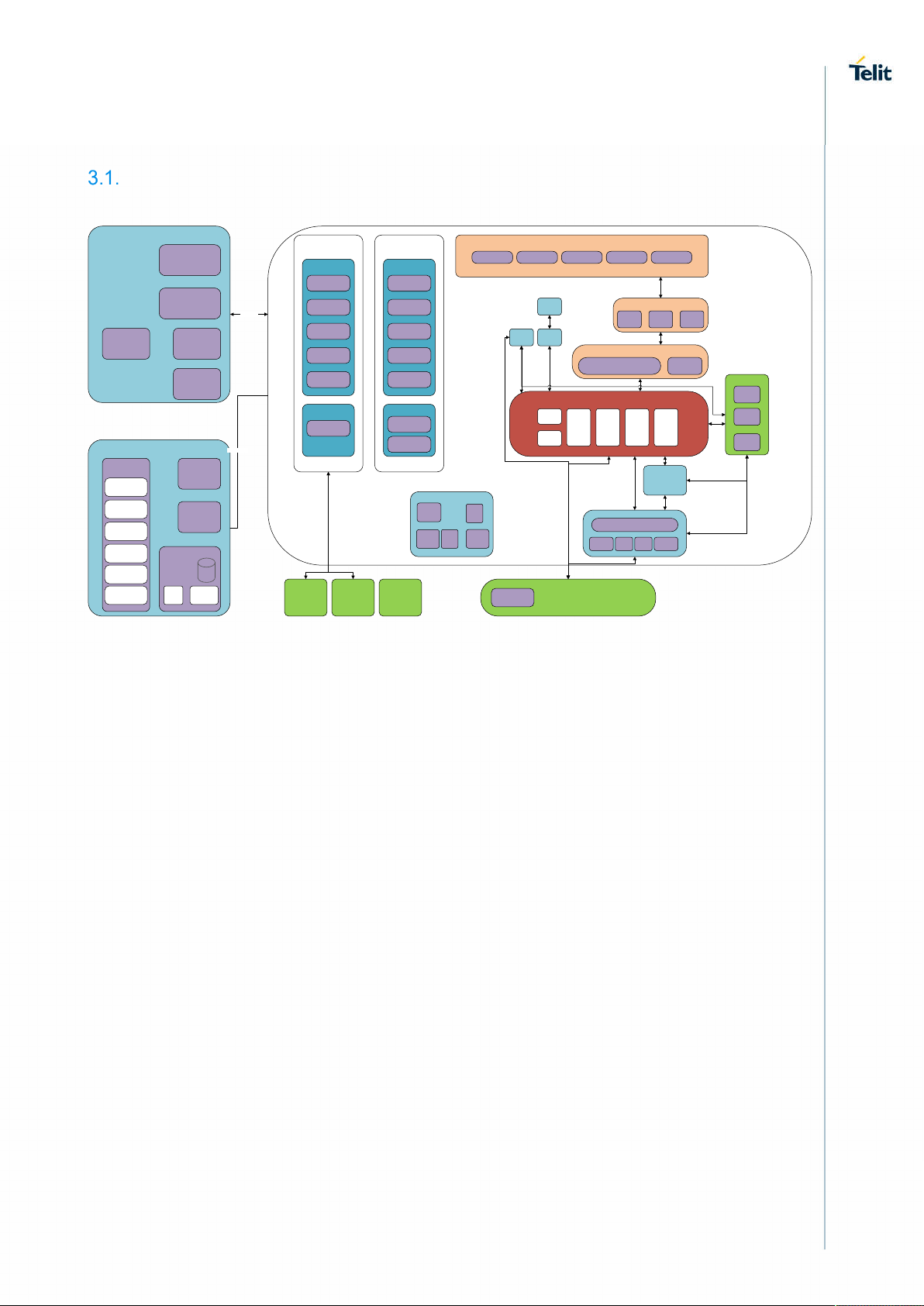
3. HIGH LEVEL SW ARCHITECTURE
Architecture based on Linux
RPM
SBL
App Core
Drivers
USB 2.0
SDIO
UART
I2C
SPI
SBL I2SCSD
Power Mgr
Resource Mgr
SPM
AVS
PBL (boot rom)
AUDIO
Register IF
SMD\SMEM
QMI
ACDB
Figure 1 : General System Architecture
Drivers
CoreBSP
CLK
SIO
SMD
UART
Data mover
Misc
UIM
Services
CoreBSP
Diag
Timers
INTC
EFS
Sleep
QURT RTOS
REX emulation
POSIX
LPASS
AFE
I2S PP
SPMIUART
Modem subsystem
NAS QOS WDS DMS PBM
GPS
CVD
Encoder
/
Decoder
IMS
Data
services
HDR
1X
Modem HWNAV coreWTRPMICSIM card
QMI services
MMOC CM SD
UMTS/GERAN/TDSCDM A NAS LTE NAS
Protocol Stack (Acc ess stratum)
GERAN UMTS
Common (CRM, FWS)
GERAN UMTS LTE
MMCP
TDSCDM
FW
MMCP
Common PHY
RX FE Link
Mgr
LTE
A
RF Driver
TDSCDM
A
TxC Link
MCPM
1VV0301556 Rev. 7
Page 13 of 145
2020-09-25
Page 14
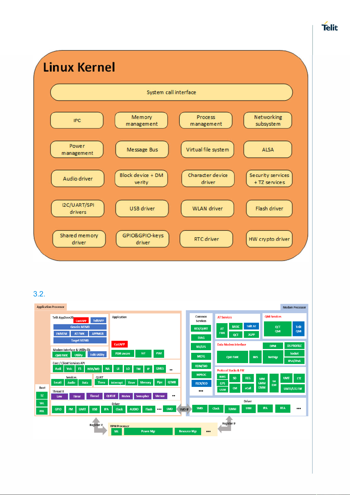
Figure 2: Linux Kernel components
Architecture based on ThreadX
1VV0301556 Rev. 7
Page 14 of 145
2020-09-25
Page 15

4. FUNCTIONAL DESCRIPTION
General Functionality and Main Features
The LE910Cx family of cellular modules feature LTE and multi-RAT modem together with an onchip powerful application processor and a rich set of interfaces.
The major functions and features are listed below:
Multi RAT cellular modem for voice and data communication
o LTE FDD/TDD Cat4 (150/50Mbps DL/UL).
o GSM/GPRS/EDGE
o WCDMA up to DC HSPA+ Rel. 9
o Support for SIM profile switching
Digital audio and analog audio codec
Application processor to run customer application code
o 1.2 GHz Cortex-A7 with Linux version 3.18
o Flash + DDR are large enough to allow for customer’s own software applications
High speed serial interfaces:
o USB, HSIC
Tools for firmware update (TFI)
Stream download protocol (SDL)
FOTA (Legacy AT FOTA)
SGMII (optional) for external Ethernet transceiver
SDIO for (optional) external Wi-Fi transceiver
Note: The LE910C1-SV/LE910C1-SA/LE910C1-ST don’t support Wi-Fi.
Note: The ThreadX products don’t support HSIC, SGMII and SDIO.
Application system overview
The Application Processor is a 32bit ARM Cortex-A7 up to 1.2GHz running the Linux operating
system. The following software is pre-integrated and is running on the application processor:
32bit Cortex-A7@1.2GHz running the Linux kernel 3.18.
Telit Unified AT command set, backward compatible with LE920, which is the main control
interface to offer features by the non-application-enabled variant, with the following:
o Hayes standard AT command set
o ETSI GSM 07.07 specific AT command and GPRS specific commands.
o ETSI GSM 07.05 specific AT commands for SMS (Short Message Service) and
CBS (Cell Broadcast Service)
o Control of pre-integrated Firmware Update Agent (Harman)
o Antenna diagnostics
Firmware Over-The-Air (FOTA) update supporting selective update. Backward compatible
with LE910.
Operator specific Device management client, backward compatible with LE910
SPI device driver for user space access of the SPI device, including slave to master
interrupt, backward compatible with LE910
GPIO interrupts driver for user space to listen to interrupts on selected user GPIOs,
backward compatible with LE910
2G/3G/4G and GNSS jamming detection
Audio subsystem, backward compatible with LE910
o PCM digital audio IO
o Limited support for DTMF detection.
1VV0301556 Rev. 7
Page 15 of 145
2020-09-25
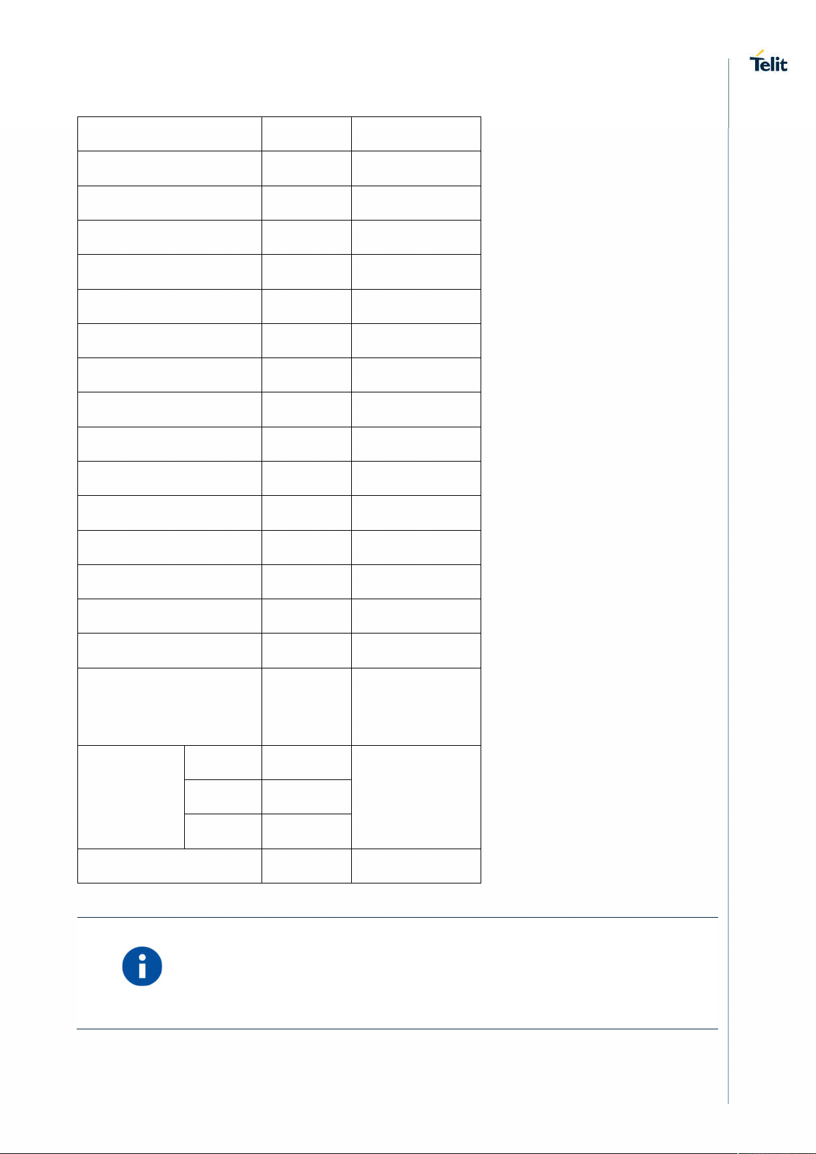
Page 16

Partition name
Permission
(MB)
RO
FTM support, backward compatible with LE910
Vocoder support and processing
o GSM vocoders (EFR/HR/FR), all rates
o AMR-NB, AMR-WB, all rates
o VoLTE
o Configurable noise suppressor, echo canceller and processing chain
Pre-integrated Wi-Fi driver via SDIO (QualcommA6574)
o USB for point to point connection (virtual COM)
ThreadX products:
Do not support SDIO.
Do not support SPI interrupt from slave.
4.2.1. Memory configuration
The LE910Cx memory configuration is as follows:
4.2.1.1. LE
Extended memory: 512Mbyte Flash /256Mbyte DDR
Regular memory: 256Mbyte Flash /256Mbyte DDR
Small memory: 256Mbyte Flash /128Mbyte DDR
4.2.1.2. TX(Thread-X)
128Mbyte Flash /128Mbyte DDR
4.2.2. Partition Layout
The below tables show the flash storage allocation on a partition basis.
Note: The size of the flash allocation includes the UBI container overhead
(usually at 15% of the partition)
Partitions marked as Telit: They are specific partitions used by Telit.
4.2.2.1. LE
Extended Memory
Partition size
1VV0301556 Rev. 7
sbl
RO
mibib
telit
RO
Page 16 of 145
1.25
1.25
3.25
2020-09-25
Page 17
RO
RO
RO
RO
RO
RO
RO
RO
RO
RO
RO
RW
RW
RW
efs2
tz
telit
rpm
telit
aboot
telit
boot
telit
modem
telit
recovery
RO
RO
RO
RO
12
1
1
0.5
0.5
1
1
11.75
0.625
57.875
0.375
11.75
recoveryfs
Customapps
(0x77e0000 ~
0x153e0000)
System
(0x153e0000
~
0x20000000)
Summary
fota
telit
telit
rootfs
cachefs
usrfs
0.5
RO
10.25
0.5
3.5
220
RO
172.125
512
1VV0301556 Rev. 7
Available memory: about 180 MB is for customer application
(custom apps partition)
Page 17 of 145
2020-09-25
Page 18
Partition name
Permission
(MB)
RO
RO
RO
RO
RO
RO
RO
RO
RO
RO
RW
Regular Memory
Partition size
sbl
mibib
telit
efs2
tz
rpm
aboot
boot
telit
modem
telit
recovery
RO
RO
RO
RO
1.25
1.25
3.25
12
1
0.5
1
11.75
0.625
57.875
0.375
11.75
recoveryfs
System
(0x71e0000
~
0x10000000)
Summary
fota
RO
0.5
10.25
telit
rootfs
cachefs
usrfs
RO
RW
0.5
142.125
256
Available memory: about 7 MB is for customer application
1VV0301556 Rev. 7
Page 18 of 145
2020-09-25
Page 19

Partition name
Permission
Partition size (MB)
RO
RO
RO
RO
RO
RO
RO
RO
RO
RW
Partition name
Permission
Partition size (MB)
RO
RO
Small Memory
sbl
mibib
telit
efs2
tz
rpm
aboot
boot
telit
modem
telit
recovery
RO
RO
RO
RO
RO
1.25
1.25
3.25
12
1
0.5
1
11.75
0.625
47.875
0.375
11.75
fota
recoveryfs
telit
System
(0x71e0000
~
0x10000000)
rootfs
cachefs
usrfs
Summary
4.2.2.2. TX(Thread-X)
SBL
MIBIB
Telit
0.5
20.25
RO
0.5
RW
RW
142.125
256
1.25
RO
1.25
2.75
1VV0301556 Rev. 7
telit
RO
Page 19 of 145
5.5
2020-09-25
Page 20

RO
RO
RO
RO
RO
RO
RO
RO
RO
RO
RO
RO
RO
RO
RO
Telit
EFS2
TZ
telit
DEVCFG
APDP
MSADP
SEC
MBA
ACDB
RPM
telit
RO
RO
RO
RO
0.5
12
2.25
2.25
0.375
0.375
0.5
0.25
0.5
0.5
0.375
0.375
QDSP
APPS
telit
telit
Cache_APPS
Cache_ACDB
misc
sec
Telit
Telit
EFS2APPS
Summary
RO
RO
RO
RO
47.25
7
7
25.875
0.25
0.25
0.25
0.25
1.25
2.125
5.5
128
4.2.3. RAM memory
LE910Cx-NF/EU/AP/LA
256Mbyte DDR, of which ~60MB will be available for customers’ application usage.
1VV0301556 Rev. 7
Page 20 of 145
2020-09-25
Page 21

LE910C1-SV/SA/ST
128Mbyte DDR, there is no available for customers’ application usage due to small memory.
No support Telit AppZone Linux
4.2.4. Customer application – Storage & configuration
Using the Telit SDK, the customer application would be installed directly into the USRFS (/data is
the mountpoint).
The customer application can also be linked to the powerup process onto predefined hookpoints:
/data/oem_earlystart.sh – This is at order 38 of the rcS (S is for Single user scripts are run
first)
/data/oemstart.sh - This is at order 43 of the rc5 (5 is for multi-user scripts)
/data/oem_poststart.sh - This is at order 99 of the rc5
Telit rootfs is RO, hence an application cannot be installed into the etc. The above method allows
the application to run at powerup. Selecting one of the above methods for application installation
should be made based on when the customer wants the application to run during powerup (early,
normal and post).
The above scripts should link to the application binary for execution (at least one of them). The
installation method as well as build/installation tools should be covered by the Telit LE910C1 SDK
document.
Configuration files are stored in three main areas:
1. Telit Linux RO FS. The configuration stored there (mainly in /etc) cannot be changed.
2. Telit RW USER FS (/data). The configuration stored there can be changed by customer
application. Examples are hosts, iproute, wlan etc. Configuration stored there are
persistent, i.e. written to the flash.
3. Telit RW RAM disk (/var/run). This is a FS mounted on the RAM directly, i.e. not persistent.
Examples are DNS, mobile AP and firewall configuration.
Customer applications are installed onto the usrfs storage (/data). This is a RW mountpoint.
The customer application will be automatically linked to the powerup process via predefined scripts
in the /data:
/data/oem_earlystart.sh – This is at order 38 of the rcS (S is for Single user scripts are run
first)
/data/oemstart.sh - This is at order 43 of the rc5 (5 is for multi-user scripts)
/data/oem_poststart.sh - This is at order 99 of the rc5
The above scripts should be then linked to any customer application that needs to automatically
run during the powerup process. Note the order of the scripts, rcS scripts runs first on a Linux
machine, rc5 script runs after (43 is first then 99).
1VV0301556 Rev. 7
Page 21 of 145
2020-09-25
Page 22
4.2.5. Power up time
4.2.5.1. LE
The following measurements were taken using a special perf build.
Non-secured device:
1. Entering kernel: 0.712747
2. Entering user space: 0.742889
3. Entering customer application: 11.046918
4. Modem out of reset: 13.774010
4.2.5.2. TX(Thread-X)
1. AT On: about 9 seconds.
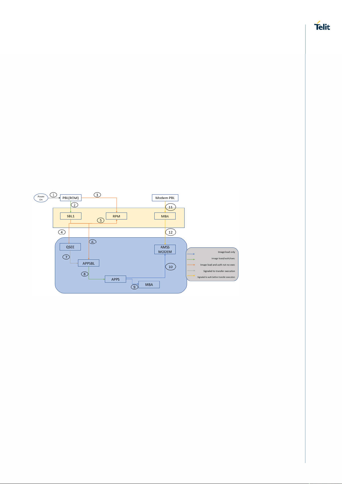
4.2.6. Power up sequence
The following figure explains the LE910Cx powerup sequence.
4.2.7. Location Subsystem
The following key features are offered by the Location subsystem:
Support for GPS, GLONASS, BeiDou/Compass Phase II, Galileo and QZSS
Supports following Satellite Based Augmentation Systems (SBAS): WAAS, EGNOS,
MSAS (only tracked for cross correlation improvement)
Receiver Autonomous Integrity Monitoring (RAIM) & Fault Detection and Exclusion (FDE)
support, internal in the receiver.
Support of assistance data (Ephemerides, location, time...) provided by customer
application to ensure faster Time To First Fix (TTFF) through SUPL and LTO injection
Periodic pulse output for synchronization to GPS system clock
NMEA-0183 output on USB
4.2.8. Application development environment
Please refer to the Telit AppZone Linux documentation in the link, below
1VV0301556 Rev. 7
Page 22 of 145
2020-09-25
Page 23

https://s3.amazonaws.com/site_support/Telit/AppZone-SDK/v4/AppZone_Guide/az-linuxuser-guide/index.html
Telit AppZone Linux is not available on LE910C1-SA, LE910C1-ST, LE910C1-SV
products, which have small memory,128Mbyte DDR and there is no RAM space for
customer application.
4.2.9. Random number generator
The LE910Cx RNG is based on FIPS-140-2 PRNG (aka hw_drbg), seeded with QC designed hw
entropy unit
consisting of the ring oscillator (RO) noise source.
There are several Linux devices to generate random numbers (under the /dev node):
1. hw_random – This is an HW random number generator, this is the preferred device to get
random data from.
2. random – This is, in most cases, a SW random generator.
Linux kernel itself (on latest kernel versions >= msm-3.18) adds HW random data to
/dev/random if randomness is not sufficient from SW RNG. Random will block if no
sufficient randomness is built up.
3. urandom – This device doesn’t care if not enough randomness exists and is not
recommended for use unless the quality of the RNG is not in concern (this device will
probably work faster).
The number of entropies used for the RNG can be checked, and modified, with the following sysfs:
/sys/module/rng_core/parameters/current_quality
Max value is 1024.
An example for reading random bytes from the hw_random:
4.2.10. Wake up Events
The Telit Modules provide a function that reduces the power consumption during the period
when they are in IDLE state (waiting for a call), allowing a longer activity with a given battery
capacity.
The power saving function can be configured in several modes in accordance with the user
needs.
In accordance with the response of the AT+CFUN=? Command, you can know the Power
Saving Modes supported by Telit Module, refer to AT Commands Reference Guide for more
details.
In power saving mode with CFUN=5, UART AT interface disabled. URC is not displayed, and it
stored in the buffer on UART AT interface. It flushed to DTE when modem device exit power
saving mode by <DTR=ON>
AT#PSMRI=<duration time> must be configured as non-zero value. It enables RI with the
specified time if URC event happened during power saving mode with CFUN=5.
1VV0301556 Rev. 7
Page 23 of 145
2020-09-25
Page 24

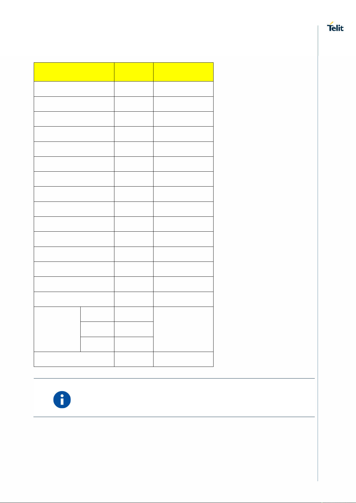
The power saving function can be waked up in several event as follows:
CFUN=0 CFUN=4 CFUN=5
Wake up Events
Unsolicited Result
Code
Incoming voice call
Incoming data
call(VoLTE)
Incoming SMS
AT+CNMI=0,0, ...
Incoming SMS
AT+CNMI=1,1, ...
Module enters NONCYCLIC SLEEP mode
The new mode depends
on URC
Incoming call is managed,
RING is displayed. The
module exits power
saving state and enters
CFUN=1 mode.
Incoming SMS is
managed, URC is not
displayed. The module
stays in power saving
state in CFUN=0 mode.
Incoming SMS is
managed, URC is
displayed. The module
exits power saving state
and enters CFUN=1
mode.
Module performs network
deregistration and SIM
deactivation.
TX and RX are disabled
The new mode depends
on URC
N/A
N/A
N/A
The power saving is
enabled. DTR is used to
exit/enter power saving.
AT#PSMRI must be
configured as non-zero
value to get URC event
via RI.
The new mode depends
on URC.
Incoming call is managed.
RI toggle. DTR is
used to exit/ enter power
saving state in CFUN=5
mode
Incoming SMS is
managed, URC is not
displayed. DTR is used to
exit/enter power saving
state in CFUN=5 mode.
Incoming SMS is
managed. DTR is used to
exit/ enter power saving
state in CFUN=5 mode.
URC is displayed when
modem device exit power
saving mode
Incoming GPRS
packet
RTC alarm CFUN=1 CFUN=4 CFUN=5
RTS toggling CFUN=1 N/A N/A
CFUN=0 N/A CFUN=5
Since RTS toggle event periodically checks pin status in CFUN=0 mode, in
worst case, it may take up to around 1 second for the module to wake up.
LE910C1-EU(4G+2G) does not allow power saving mode because HSIC
configuration of LE910C1-EU(4G+2G) is master mode. To support power
saving mode, HSIC configuration need to be disabled by #HSICEN=0
(Manual reboot is required) or please refer to section 4.2.17
1VV0301556 Rev. 7
Page 24 of 145
2020-09-25
Page 25

4.2.10.1. Wake up Event Examples
4.2.10.1.1. CFUN=0: Call, SMS, #QSS, +CALA
Example 1
The wake-up event is an incoming call.
Starting control line configuration, UART AT interface is enabled.
<DSR=ON>, RI=OFF, DCD=OFF, <CTS=ON>, RTS=ON, DTR=ON
Type in CFUN=0, the module enters NON-CYCLIC SLEEP mode.
AT+CFUN=0
OK
Here is the new control line configuration. The module is in power saving.
<DSR=OFF>, RI=OFF, DCD=OFF, <CTS=OFF>, RTS=ON, DTR=ON
An incoming call is arrived.
RING
Here is the new control line configuration. The module is no longer in power saving.
<DSR=ON>, RI=ON, DCD=OFF, <CTS=ON>, RTS=ON, DTR=ON
RING
Check the current CFUN.
AT+CFUN?
+CFUN: 1 the module is in full functionality mode
OK
RING
Hang up the call.
ATH
OK
Here is the new control line configuration.
<DSR=ON>, RI=OFF, DCD=OFF, <CTS=ON>, RTS=ON, DTR=ON
Example 2
The wake-up event is a SMS receiving.
Enable URC created by the SMS receiving.
AT+CNMI=1,1,0,0,0
OK
Starting control line configuration, UART AT interface is enabled.
<DSR=ON>, RI=OFF, DCD=OFF, <CTS=ON>, RTS=ON, DTR=ON
Type in CFUN=0, the module enters NON-CYCLIC SLEEP mode.
AT+CFUN=0
OK
1VV0301556 Rev. 7
Page 25 of 145
2020-09-25
Page 26

Here is the new control line configuration. The module is in power saving.
<DSR=OFF>, RI=OFF, DCD=OFF, <CTS=OFF>, RTS=ON, DTR=ON
A SMS is arrived.
+CMTI: "SM",17
Here is the new control line configuration. The module is no longer in power saving.
<DSR=ON>, RI=OFF, DCD=OFF, <CTS=ON>, RTS=ON, DTR=ON
Check the current CFUN.
AT+CFUN?
+CFUN: 1 the module is in full functionality mode
OK
Example 3
The wake-up event is the #QSS URC.
Starting control line configuration, UART AT interface is enabled.
<DSR=ON>, RI=OFF, DCD=OFF, <CTS=ON>, RTS=ON, DTR=ON
Enable Query SIM Status URC.
AT#QSS=1
OK
Type in CFUN=0, the module enters NON-CYCLIC SLEEP mode.
AT+CFUN=0
OK
Here is the new control line configuration. The module is in power saving.
<DSR=OFF>, RI=OFF, DCD=OFF, <CTS=OFF>, RTS=ON, DTR=ON
Extract the SIM. After a while, the DTE displays the following URC:
#QSS:0
Here is the new control line configuration. The module is no longer in power saving.
<DSR=ON>, RI=OFF, DCD=OFF, <CTS=ON>, RTS=ON, DTR=ON
Check the current CFUN mode.
AT+CFUN?
+CFUN: 1 the module is in full functionality mode
OK
Example 4
+CALA URC event forces the module in CFUN=1 mode.
Starting control line configuration, UART AT interface is enabled.
<DSR=ON>, RI=OFF, DCD=OFF, <CTS=ON>, RTS=ON, DTR=ON
Set the clock
AT+CCLK="08/05/16,09:20:30+00"
OK
Set when the alarm wakes up: in two minutes (it is just an example).
1VV0301556 Rev. 7
Page 26 of 145
2020-09-25
Page 27

AT+CALA="08/05/16,09:22:30+00",0,2,"ALARM, ALARM, ALARM"
OK
Type in CFUN=0, the module enters NON-CYCLIC SLEEP mode.
AT+CFUN=0
OK
Here is the new control line configuration. The module is in power saving.
<DSR=OFF>, RI=OFF, DCD=OFF, <CTS=OFF>, RTS=ON, DTR=ON
During the ALARM waiting, the module is in power saving and UART AT interface is disabled.
When the alarm wakes up, the DTE displays the URCs. The module exits power saving in
CFUN=0 mode and enters CFUN=1 mode.
+CALA: ALARM, ALARM, ALARM
Here is the new control line configuration.
<DSR=ON>, RI=OFF, DCD=OFF, <CTS=ON>, RTS=ON, DTR=ON
+CALA: ALARM, ALARM, ALARM
Check the alarm mode
AT#WAKE?
#WAKE: 1 the module is in alarm mode
OK
+CALA: ALARM, ALARM, ALARM
Check the current CFUN.
AT+CFUN?
+CFUN: 1 the module is in full functionality mode
OK
+CALA: ALARM, ALARM, ALARM
+CALA: ALARM, ALARM, ALARM
After 90 sec, the module exits alarm mode.
Check the alarm mode.
AT#WAKE?
#WAKE: 0 the module exited alarm mode
OK
4.2.10.1.2. CFUN=4: #QSS, +CALA
Example 1
#QSS URC event leaves the module in CFUN=4 mode.
Starting control line configuration, UART AT interface is enabled.
<DSR=ON>, RI=OFF, DCD=OFF, <CTS=ON>, RTS=ON, DTR=ON
1VV0301556 Rev. 7
Page 27 of 145
2020-09-25
Page 28

Type in CFUN=4, the module performs network deregistration, and SIM deactivation.
AT+CFUN=4
OK
Control line configuration is not changed.
<DSR=ON>, RI=OFF, DCD=OFF, <CTS=ON>, RTS=ON, DTR=ON
Enable Query SIM Status URC.
AT#QSS=1
OK
Extract the SIM. The URC does not arrive because CFUN=4 mode deactivates the SIM.
The module stays in CFUN=4 mode.
AT+CFUN?
+CFUN: 4
OK
Example 2
+CALA URC event leaves the module in CFUN=4 mode.
Starting control line configuration, UART AT interface is enabled.
<DSR=ON>, RI=OFF, DCD=OFF, <CTS=ON>, RTS=ON, DTR=ON
Set the clock
AT+CCLK="08/05/16,09:20:30+00"
OK
Set when the alarm wakes up: in two minutes (it is just an example).
AT+CALA="08/05/16,09:22:30+00",0,2,"ALARM, ALARM, ALARM"
OK
Type in CFUN=4, the module performs network deregistration, and SIM deactivation.
AT+CFUN=4
OK
Control line configuration is not changed
<DSR=ON>, RI=OFF, DCD=OFF, <CTS=ON>, RTS=ON, DTR=ON
When the alarm wakes up, the DTE displays the URCs.
+CALA: ALARM, ALARM, ALARM
Control line configuration is not changed.
<DSR=ON>, RI=OFF, DCD=OFF, <CTS=ON>, RTS=ON, DTR=ON
+CALA: ALARM, ALARM, ALARM
Check the alarm mode
AT#WAKE?
#WAKE: 1 the module is in alarm mode
OK
+CALA: ALARM, ALARM, ALARM
The module does not change CFUN mode.
AT+CFUN?
+CFUN: 4
1VV0301556 Rev. 7
Page 28 of 145
2020-09-25
Page 29

OK
+CALA: ALARM, ALARM, ALARM
After 90 sec, the module exits alarm mode.
Check the alarm mode.
AT#WAKE?
#WAKE: 0 the module exited alarm mode
OK
The module does not change CFUN mode.
AT+CFUN?
+CFUN: 4
OK
4.2.10.1.3. CFUN=5: Call, SMS, +CALA
Example 1
The wake-up event is an incoming call.
Starting control line configuration, UART AT interface is enabled.
<DSR=ON>, RI=OFF, DCD=OFF, <CTS=ON>, RTS=ON, DTR=ON
Force the module in CFUN=5 mode, the power saving is enabled.
AT+CFUN=5
OK
Control line configuration does not change, UART AT interface is still enabled.
<DSR=ON>, RI=OFF, DCD=OFF, <CTS=ON>, RTS=ON, DTR=ON
Force the module in power saving.
DTR OFF
The module is in power saving, and UART AT interface is disabled.
<DSR=OFF>, RI=OFF, DCD=OFF, <CTS=OFF>, RTS=ON, DTR=OFF
An incoming call is arrived
Here is the new control line configuration: RI=ON
<DSR=OFF>, RI=ON, DCD=OFF, <CTS=OFF>, RTS=ON, DTR=OFF
Exit power saving, and UART AT interface is enabled
DTR ON
<DSR=ON>, RI=ON, DCD=OFF, <CTS=ON>, RTS=ON, DTR=ON
The module exits power saving, but stays in CFUN=5 mode.
AT+CFUN?
+CFUN:5
OK
1VV0301556 Rev. 7
Page 29 of 145
2020-09-25
Page 30

RING
Hang up the call.
ATH
OK
Enter power saving.
DTR OFF
The module enters again the power saving mode, and UART AT interface is disabled.
<DSR=OFF>, RI=OFF, DCD=OFF, <CTS=OFF>, RTS=ON, DTR=OFF
Example 2
The wake-up event is a SMS receiving.
Enable URC created by the SMS receiving.
AT+CNMI=1,1,0,0,0
OK
Set AT#PSMRI to get URC event during power saving mode
AT#PSMRI=1000
OK
Starting control line configuration, UART AT interface is enabled.
<DSR=ON>, RI=OFF, DCD=OFF, <CTS=ON>, RTS=ON, DTR=ON
Force the module in CFUN=5 mode, the power saving is enabled.
AT+CFUN=5
OK
Control line configuration does not change, UART AT interface is still enabled.
<DSR=ON>, RI=OFF, DCD=OFF, <CTS=ON>, RTS=ON, DTR=ON
Force the module in power saving.
DTR OFF
The module is in power saving and UART AT interface is disabled.
<DSR=OFF>, RI=OFF, DCD=OFF, <CTS=OFF>, RTS=ON, DTR=OFF
A SMS is arrived and it stored in the buffer on UART AT interface and RI is ON during 1 sec
<DSR=OFF>, RI=ON, DCD=OFF, <CTS=OFF>, RTS=ON, DTR=OFF
The module is still in power saving and UART AT interface is disabled.
<DSR=OFF>, RI=OFF, DCD=OFF, <CTS=OFF>, RTS=ON, DTR=OFF
Exit power saving, and AT interface enabled. The buffered URC displayed
DTR ON
+CMTI: "SM",17
<DSR=ON>, RI=OFF, DCD=OFF, <CTS=ON>, RTS=ON, DTR=ON
1VV0301556 Rev. 7
Page 30 of 145
2020-09-25
Page 31

The module exits power saving but stays in CFUN=5 mode.
AT+CFUN?
+CFUN:5
OK
Enter power saving.
DTR OFF
The module enters again the power saving mode, and UART AT interface is disabled.
<DSR=OFF>, RI=OFF, DCD=OFF, <CTS=OFF>, RTS=ON, DTR=OFF
Example 3
The wake-up event is a SMS receiving
Check the number of SMS already arrived.
AT+CPMS?
+CPMS: "SM",18,30,"SM",18,30,"SM",18,30 Yes, a new SMS is arrived.
OK
Disable URC created by the SMS receiving.
AT+CNMI=0,0,0,0,0
OK
Starting control line configuration, UART AT interface is enabled.
<DSR=ON>, RI=OFF, DCD=OFF, <CTS=ON>, RTS=ON, DTR=ON
Force the module in CFUN=5 mode, the power saving is enabled.
AT+CFUN=5
OK
Control line configuration does not change, UART AT interface is still enabled.
<DSR=ON>, RI=OFF, DCD=OFF, <CTS=ON>, RTS=ON, DTR=ON
Force the module in power saving.
DTR OFF
The module is in power saving and UART AT interface is disabled.
<DSR=OFF>, RI=OFF, DCD=OFF, <CTS=OFF>, RTS=ON, DTR=OFF
A SMS is sent and arrived. The DTE does not displays the URC +CMTI.
The module is still in power saving and UART AT interface is disabled.
<DSR=OFF>, RI=OFF, DCD=OFF, <CTS=OFF>, RTS=ON, DTR=OFF
Exit power saving and enable again the hardware flow control of the serial line.
DTR ON
<DSR=ON>, RI=OFF, DCD=OFF, <CTS=ON>, RTS=ON, DTR=ON
The module exits power saving but stays in CFUN=5 mode.
AT+CFUN?
+CFUN:5
OK
Check if a new SMS is arrived.
AT+CPMS?
1VV0301556 Rev. 7
Page 31 of 145
2020-09-25
Page 32

+CPMS: "SM",19,30,"SM",19,30,"SM",19,30 Yes, a new SMS is arrived.
OK
Enter power saving.
DTR OFF
The module enters again the power saving mode, and UART AT interface is disabled.
<DSR=OFF>, RI=OFF, DCD=OFF, <CTS=OFF>, RTS=ON, DTR=OFF
Example 4
+CALA URC event leaves the module in CFUN=5 mode.
Starting control line configuration, AT interface is enabled.
<DSR=ON>, RI=OFF, DCD=OFF, <CTS=ON>, RTS=ON, DTR=ON
Force the module in CFUN=5 mode, the power saving is enabled.
AT+CFUN=5
OK
Control line configuration does not change, UART AT interface is still enabled.
<DSR=ON>, RI=OFF, DCD=OFF, <CTS=ON>, RTS=ON, DTR=ON
Set the clock
AT+CCLK="08/05/16,09:20:30+00"
OK
Set when the alarm wakes up: in two minutes (it is just an example).
AT+CALA="08/05/16,09:21:30+00",0,2,"ALARM, ALARM, ALARM"
OK
Set AT#PSMRI to get URC event during power saving mode
AT#PSMRI=1000
OK
Force the module in power saving.
DTR OFF
During the ALARM waiting, the module is in power saving, and UART AT interface is disabled.
<DSR=OFF>, RI=OFF, DCD=OFF, <CTS=OFF>, RTS=ON, DTR=OFF
When the alarm time is expired, URC event take place. It stored in the buffer on UART AT
interface. and RI is ON during 1 sec
<DSR=OFF>, RI=ON, DCD=OFF, <CTS=OFF>, RTS=ON, DTR=OFF
UART AT interface is disabled.
Now, enable UART AT interface. The module exits power saving, and the buffered URC flushed
to DTE. but stays in CFUN=5 mode.
DTR ON
<DSR=ON>, RI=OFF, DCD=OFF, <CTS=ON>, RTS=ON, DTR=ON
+CALA: ALARM, ALARM, ALARM
+CALA: ALARM, ALARM, ALARM
1VV0301556 Rev. 7
Page 32 of 145
2020-09-25
Page 33

Check if the module is in alarm mode.
AT#WAKE?
#WAKE: 1
OK
+CALA: ALARM, ALARM, ALARM
Check the current CFUN.
AT+CFUN?
+CFUN: 5
OK
+CALA: ALARM, ALARM, ALARM
After 90 sec the module exits alarm mode.
AT#WAKE?
#WAKE: 0
OK
Check the current CFUN.
AT+CFUN?
+CFUN: 5
OK
Force the module in power saving.
DTR OFF
The module is in power saving in CFUN=5 mode, and UART AT interface is disabled.
<DSR=OFF>, RI=OFF, DCD=OFF, <CTS=OFF>, RTS=ON, DTR=OFF
4.2.11. SPI
The LE910Cx includes a Serial Peripheral Interface (SPI) bus supporting:
Master mode at max 50 MHz
Programmable data bits (4 to 32 bits)
Programmable spacing between byte/word transfers (SPI_CS_N WAIT)
Programmable transfer length (number of bytes transferred within each SS/CS assertion)
LE910Cx has one SPI core using BLSP (board low speed peripheral).
The BLSP includes a UART and QUP (Qualcomm universal peripheral) cores.
This QUP has an SPI/I2C mini cores.
These mini cores implement the following logic:
A common output FIFO provides system output data to one or more mini cores
A common input FIFO provides system input data from one or more mini cores
These cores use BAM (Bus access module) to move data to/from the peripheral buffers. There is
a pair of BAM pipes attached to each peripheral.
BAM block periodically reads the input FIFO until the programmed number of words are received.
1VV0301556 Rev. 7
Page 33 of 145
2020-09-25
Page 34

BAM block periodically populates the output FIFO until the programmed number of words are
written to the output FIFO.
Interrupt is generated once transfer completes.
Two H/W Pins of SPI are shared with Aux UART, so SPI and Aux UART
couldn’t be used at the same time. If SPI want to be used, please use #SPIEN
and #SPICFG commands.
ThreadX products don’t support #SPICFG.
4.2.11.1. LE (Linux)
TGPIO 1-10 (customer allocated GPIO) can be configured as an interrupt source of a SPI
master device. This allows an SPI slave device to notify the SPI master device of data being
transferred.
4.2.11.2. TX (ThreadX)
SPI functionality is only provided to customer through AppZone framework. Please refer to 4.2.7
chapter for detailed information.
4.2.12. GPIO-Keys
The GPIO-keys module provides a way for an application, running on the Linux side, to listen to
interrupts on a GPIO. GPIO 1-10 can be used for this purpose.
Application can then listen to /dev/input/event1 to get the interrupt and the interrupt data.
There are several GPIOs that are able to wake up the system from sleep. When using such a
GPIO with the GPIO-KEYS driver, any interrupt on this line will wake the system. Using a GPIO
that is not capable of waking up the system with the GPIO-KEYS driver will PREVENT THE
SYSTEM FROM GOING INTO SLEEP (the logic is very simple: if there is an interrupt pending on
a non-wakeup capable GPIO, do not go to sleep).
The GPIO-Keys module has two parameters:
tgpios – An array of tgpios to listen on. For example, tgpios=4,5 will have the driver to listen
to tgpio4 and tgpio5.
pull_arr – An optional array of pull settings to apply to each tgpio used. Available options
are:
o 0 – No Pull
o 1 – Pull Up
o 2 – Pull Down
o 3 – Default
For example, to start the gpio-keys driver listen on tgpio 4 (no pull) and tgpio 5 (pull up), use the
following command: “insmod /data/gpio-keys tgpios=4,5 pull_arr=0,1”
The number of tgpios parameters must match the number of pull_arr parameters, otherwise
pull_arr is totally ignored.
1VV0301556 Rev. 7
Page 34 of 145
2020-09-25
Page 35

The following GPIOs are wake up capable (All other GPIOs are not wakeup capable):
GPIO1
GPIO5
GPIO8
Some GPIOs (GPIO-1, GPIO-5~9) should not be pulled high externally (by the
carrier board) during module power on procedure. Pulling those pads high during
module power up might lead to unwanted/non-operational boot mode.
(See “Hardware User Guide”)
ThreadX products don’t support GPIO-Keys.
4.2.13. Serial interfaces
4.2.13.1. LE (Linux)
4.2.13.1.1. Apps to external MCU
The LE910Cx includes serial interfaces (cdc-acm and raw data interfaces) over both the UART
and USB physical interfaces. These interfaces are accessible from the Linux side and can be
used to communicate with an external MCU.
The UART device nodes are:
/dev/ttyHS0 – This is the high speed UART (the modem port). This port is in use by the
modem as an AT command port. An application that wants to use this port for
communication with an external MCU should first stop the modem service that runs on top
of this port using the following command: “/sbin/ds_uart_script stop”
/dev/ttyHSL0 – This is the debug console port. This port is in use by default as a console
(except for performance builds that disables the console capabilities). This port cannot be
relocated to othert purposes in a non-perf build.
The USB device nodes are:
/dev/ttyGSX (X is a number) – Depending on the selected USB composition, there might
be one or several ttyGS ports. For example, USB composition 1201 includes a single
ttyGS0 port (in 1201 this port is meant for NMEA sentences sent by the modem). This is a
gadget serial interface and can be used as a standard tty port to communicate with an
external MCU if NMEA sentences are not enabled.
ttyGS ports represents:
o NMEA ports - These ports are used by the modem to dump NMEA sentences.
This port is disabled by default, and are enabled when the user activates it via the
following AT commands:
1VV0301556 Rev. 7
Page 35 of 145
2020-09-25
Page 36

/dev # ls -l /dev/smd*
AT$GPSP=1
AT$GPSNMUN=1,1,1,1,1,1,1
If NMEA ports are not enabled, these ports can be used by the application to communicate with
an external MCU.
There is no other device nodes rather than ttyGS for USB. The USB driver does not export any
other USB interface via the dev file system, i.e. no ttyUSB ports will be shown for the
diag/AT/SAP usb interfaces.
4.2.13.1.2. Apps to Modem
Modem and apps are communicating via shared memory. The devices used for such
communication are smd devices and are present in the /dev/node. It is not recommended to
work with these ports directly, Telit uses these ports for several use cases and a change there
might break these functionalities.
The following is the list of smd channels available on the apps:
crw-rw---- 1 root root 248, 11 Jan 1 1970 /dev/smd11
crw-rw---- 1 root root 248, 2 Jan 6 01:58 /dev/smd2
crw-rw---- 1 root root 248, 21 Jan 1 1970 /dev/smd21
crw-rw---- 1 root root 247, 1 Jan 1 1970 /dev/smd22
crw-rw---- 1 root root 248, 36 Jan 1 1970 /dev/smd36
crw-rw---- 1 root root 248, 7 Jan 1 1970 /dev/smd7
crw-rw---- 1 root root 248, 8 Jan 6 01:58 /dev/smd8
crw-rw---- 1 root root 248, 9 Jan 1 1970 /dev/smd9
/dev/smd8 is used by the ttyHS0 for AT commands over the UA1RT.
/dev/smd9 is used by the MCM_ATCOP for AT commands sent via the mcm interfaces.
/dev/smd2 is free for customer use in all LE910Cx models (not available for all LE910C1
models). User can send an AT command via this smd channel and capture a response as
following:
1VV0301556 Rev. 7
Page 36 of 145
2020-09-25
Page 37

/dev # cat /dev/smd2&
/dev # echo -e "at\r\n" > /dev/smd2
/dev # at
OK
/dev # echo -e "at+cpin?\r\n" > /dev/smd2
/dev # at+cpin?
+CPIN: READY
OK
Other smd channels are used internally by Telit/QC and cannot be accessed by user.
4.2.14. Audio
4.2.14.1. LE
Audio subsystem
Optional embedded analog codec with two microphone inputs
Optional embedded analog codec with one stereo or two mono outputs
PCM digital audio IO
o Clock Type: Master
o Short frame sync
o Data format 16 –bit linear
o <clock>
128 – DVI Clock activated at 128KHz
256 – DVI Clock activated at 256KHz
512 – DVI Clock activated at 512KHz
1024 – DVI Clock activated at 1024KHz
2048 – DVI Clock activated at 2048KHz
4096 – DVI Clock activated at 4096KHz
o <samplerate>
8KHz
16KHz
The Audio user space Application purpose is to:
1. Configure and control the audio properties such as Volume, clock, device mute etc.
2. Use UCM file to configure audio paths and audio devices (handset, hands-free ...)
3. Use AMIX to send commands and data to the ALSA.
4. Manage all voice call events for audio.
5. Manage the digital (external codec) and analog (internal codec) use cases.
Data communication between MAXIM9867 and MDM9628 is via a dedicated Aux PCM interface.
1VV0301556 Rev. 7
Page 37 of 145
2020-09-25
Page 38

Audio Application
UCM
ALSA Kernel audio subsystem
ASoC
HW
UCM is the user space library that provides C API for clients.
ALSA is the kernel audio subsystem which abstracts the PCM and controls.
ASoC is the low-level driver subsystem.
The ACDB file contains audio calibration data and is categorized as following:
Handset_cal.acdb − Contains calibration data for handset devices
Speaker_cal.acdb − Contains calibration data for speakerphone (handheld, handsfree)
devices
Headset_cal.acdb − Contains calibration data for headset devices
Bluetooth_cal.acdb − Contains BT devices for voice and audio (not supported)
Global_cal.acdb − Contains voice and audio stream calibration that is independent of
device, and other global calibration
Hdmi_cal.acdb − Contains HDMI audio playback device (not supported)
General_cal.acdb − Contains general calibration data not falling in any of the other
categories.
The LE910Cx has several locations to search ACDB files, which allows customer to override
Telit defaults as well as work with QC tools. These ACDB sets of files are searched in the order
below:
1. /data/acdb/acdbdata. This is usually where the QC tool put the calibration data
when used.
2. Code defaults. This is Telit defaults. We will fall back into this if none of the above
exists.
This basically allows the customer to calibrate audio via the QC tool and apply. If the calibration
data is accepted, the customer puts the calibration files into its rom volume and the device will
automatically pick this up in the next power up.
Command-line examples for using the ALSA soundcard driver :
Record an active voice call (analog audio):
1VV0301556 Rev. 7
Page 38 of 145
2020-09-25
Page 39

o amix 'MultiMedia1 Mixer AUX_PCM_MAX9867_UL_TX' 1
o amix 'Input Mixer' 1
o arec -D hw:0,0 -R 8000 -C 1 file.wav
Record an active voice call (digital audio):
o amix 'MultiMedia1 Mixer AUX_PCM_UL_TX' 1
o arec -D hw:0,0 -R 8000 -C 1 file4.wav
Play an audio file:
o amix 'AUX_PCM_MAX9867_RX Audio Mixer MultiMedia1' 1
o aplay filename.wav
4.2.14.2. TX (Thread-X)
Audio subsystem
Optional embedded analog codec with two microphone inputs
Optional embedded analog codec with one stereo or two mono outputs
I2S digital audio IO
o Clock Type: Master
o 16bit sample width
o <clock>
256 – DVI Clock activated at 256KHz
512 – DVI Clock activated at 512KHz
o <samplerate>
8KHz
16KHz
o Clock 256KHz supports only Sample Rate 8KHz
o Clock 512KHz supports only Sample Rate 16KHz
4.2.15. UART
The LE910Cx has two UART interface, Main and Aux.
Main UART interface is a 4-wires UART with max data rates up to 3.75 Mbps and acts as DUN
channel as default.
Aux UART interface is a 2-wires UART acting as DUN channel as default.
Following baud rates are supported:
300,600,1200,2400,4800,9600,19200,38400,57600,115200,230400,460800,921600,2000000,2
500000,3000000,3500000,3750000
4.2.15.1. LE (Linux)
If the Customer does not need a UART modem port, then can access the TTY device created
under the dev file-system. This device can be accessed from user space to read/write data to a
peripheral connected to the LE910Cx.
The TTY device can be configured with the STTY utility (included).
To tear down the UART to modem connection, use this command:
1VV0301556 Rev. 7
Page 39 of 145
2020-09-25
Page 40

/sbin/ds_uart_script stop
After this, the ttyHS0 can be directly accessed (/dev/ttyHS0) from Linux user space for read/write
to an external processor connected on the other side.
4.2.16. USB Interface
The LE910Cx includes a USB2.0 compliant Universal Serial Bus (USB) Transceiver, which
operates at USB high-speed (480Mbits/sec). By default, the module is configured as a USB
peripheral.
4.2.16.1. LE (Linux)
The USB port is typically used for:
Flashing of firmware and module configuration
Production testing
Accessing the Application Processor’s filesystem (debug bridge)
AT command access (2 modem ports)
High speed WWAN access to external host
Diagnostic monitoring and debugging
NMEA data to an external host CPU
The following standardized device classes can be supported:
Serial (reduced ACM), CDC-ECM, MBIM, RMNET (Qualcomm proprietary)
Audio Device class, but limited to voice Rx & Tx and only when in peripheral mode
Note: When the module is attached to USB serial driver on Linux platform, DIAG port, MODEM
ports and NMEA port will be created as “/dev/ttyUSBx” not “/dev/ttyACMx”. Please refer to
“Telit_Modules_USB_Drivers_User_Guide”.
The following USB compositions are available:
1200 - NONE
1201 - DIAG + ADB + RMNET + NMEA + MODEM + MODEM + SAP
1203 - RNDIS + DIAG + ADB + NMEA + MODEM + MODEM + SAP
1204 - DIAG + ADB + USB_MBIM + NMEA + MODEM + MODEM + SAP
1205 - USB_MBIM
1206 - DIAG + ADB + ECM + NMEA + MODEM + MODEM + SAP
1250 - RMNET + NMEA + MODEM + MODEM + SAP
1251 - RNDIS + NMEA + MODEM + MODEM + SAP
1252 - USB_MBIM + NMEA + MODEM + MODEM + SAP
1253 - ECM + NMEA + MODEM + MODEM + SAP
1254 - MODEM + MODEM
1255 - NMEA + MODEM + MODEM + SAP
1230 - DIAG + ADB + RMNET + AUDIO + NMEA + MODEM + MODEM + SAP
1231 - RNDIS + DIAG + ADB + AUDIO + NMEA + MODEM + MODEM + SAP
1260 - DIAG + ADB + RMNET + NMEA + MODEM + MODEM + SAP
1261 - DIAG + ADB + RMNET + NMEA + MODEM + MODEM + SAP
1VV0301556 Rev. 7
Page 40 of 145
2020-09-25
Page 41

The USB composition can be changed using the usb_composition utility on the Linux side as
well as using the #USBCFG AT command (covered by the LE910Cx AT user guide). The
usb_composition utility can be used to select any of the above compositions list.
The 125X USB compositions are made specifically for customers that are willing to allow the
LE910Cx device to sleep even if the USB is connected (Enables the USB selective suspend).
The USB selective suspend also depends on the host implementation.
How to change USB composition in MBIM only USB composition.
Note that on Linux operating system only, the following commands can be used.
Please send MBIM_OPEN message to modem with the following command and wait 3
sec.
echo 01 00 00 00 10 00 00 00 01 00 00 00 00 10 00 00 | xxd -r -p >/dev/cdc-wdm0
Please send USB composition with the following command
echo 03 00 00 00 32 00 00 00 05 00 00 00 01 00 00 00 00 00 00 00 54 65 6c 69 74 4d 42
49 4d 45 78 74 65 6e 64 53 01 00 00 00 01 00 00 00 02 00 00 00 XX 00 | xxd -r -p
>/dev/cdc-wdm0
The red number should be changed to set USB configuration and the range of red number
is 0x00-0x0c.
4.2.16.2. TX (ThreadX)
The USB port is typically used for:
Flashing of firmware and module configuration
Production testing
AT command access (2 modem ports)
High speed WWAN access to external host
Diagnostic monitoring and debugging
The following standardized device classes can be supported:
Serial (reduced ACM), CDC-ECM, RMNET (Qualcomm proprietary)
Note: When the module is attached to USB serial driver on Linux platform, DIAG port and MODEM
ports will be created as “/dev/ttyUSBx” not “/dev/ttyACMx”. Please refer to
“Telit_Modules_USB_Drivers_User_Guide”.
The following USB compositions are available:
1031 - DIAG + MODEM + MODEM + RMNET
1033 - DIAG + MODEM + MODEM + ECM
1034 - MODEM + MODEM + RMNET
1035 - MODEM + MODEM + ECM
1036 - MODEM + MODEM
The USB composition can be changed by #USBCFG AT command (covered by the LE910Cx AT
user guide).
4.2.17. HSIC Interface
The LE910Cx includes a 2-wire HSIC (High-Speed Inter-Chip) interface and the interface
supports HSIC master or slave mode.
1VV0301556 Rev. 7
Page 41 of 145
2020-09-25
Page 42

The HSIC interface of LE910Cx supports the following feature:
No hot plug detection
No hot removal/attach, interface is always connected
No high-speed chirp protocols
HSIC master/ slave mode support
The HSIC configuration can be changed using #HSICEN command and manual reboot is required.
Example 1
Enable HSIC master mode.
AT#HSICEN=1
OK
Example 2
Enable HSIC slave mode.
AT#HSICEN=2
OK
Example 3
Disable HSIC configuration.
AT#HSICEN=0
OK
How to make power saving mode when HSIC configuration of LE910Cx is master mode (master
and slave connected state)
Before set CFUN to 5, please do the following command on apps
echo auto > /sys/bus/usb/devices/1-1/power/control
If HSIC configuration of LE910Cx is slave mode, the LE910Cx does not
allow power saving mode because the signals of between HSIC master and
slave resume are not sync.
If HSIC configuration of LE910Cx is master mode, power saving mode can
only be entered in HSIC master and slave connected state.
ThreadX products don’t support HSIC interface.
4.2.18. SD/MMC Interface
LE910Cx provides an SD port supporting the SD3.0 specification, which can be used to support
standard SD/MMC memory cards.
Please refer to the “LE910Cx Linux device driver Application Note” document for more details.
1VV0301556 Rev. 7
ThreadX products don’t support SDIO interface.
Page 42 of 145
2020-09-25
Page 43

4.2.19. RTC
LE910Cx includes an RTC (Real Time Clock), allowing an application to set an alarm to either
wake up the module from sleep mode, power up the module or simply interrupt once the alarm
expires. The interface to the RTC, from SW perspective, is made via the RTC device exposed in
the device file system (standard RTC device interface).
The RTC driver handles the RTC time and alarm requests from the user.
The RTC sysfs interface can be seen at: /sys/class/rtc/rtc0/
User can set the RTC for wake alarm (using RTC_WKALM_SET ioctl) and receive the
notification through the RTC device interface (/dev/rtc0). Another way is to set the RTC wake
alarm, shutdown the module (shutdown –h now) and the device will power up automatically
when the alarm expires.
In order to allow user space to know why the device has powered up, the following file was
added:/var/volatile/tmp/rtc_wake_status.
If the file contains 0 as value, this basically means a normal user selected power up. 1 means
power up due to RTC alarm expiration.
ThreadX products don’t support RTC interface.
4.2.20. Time Services
The time daemon manages the system time between the modem and the apps processor.
The time daemon service starts during boot, and it reads the RTC time from /dev/rtc0 and the
offset from file /data/time/ats_1 (or /var/tmp/time/ in older versions). This value is then set as the
system time.
When the system boots and time daemon initialize for the first time, the daemon reads the file at
/data/time/ats_1 to initialize the offset value. Therefore, as long as the files are present and
contain the correct values, the system time is preserved after system reboot.
4.2.20.1. Coordinated Universal Time (UTC)
The UTC time standard is used to regulate the world clock and time. UTC is based on
International Atomic Time (TAI), and time zones around the world are expressed as positive or
negative offsets from UTC.
UTC is the time standard used for many Internet and web standards. The Network Time
Protocol, designed to synchronize the clocks of computers over the Internet, encodes times
using the UTC system.
UTC is helpful to avoid confusion about time zones and daylight saving time.
4.2.20.2. Time zones
The time zones around the world are expressed as positive or negative offsets from UTC.
1VV0301556 Rev. 7
Page 43 of 145
2020-09-25
Page 44

4.2.20.3. Daylight Saving Time (DST)
DST is observed in some time zones by advancing the time by some duration in summer and
reverting to the original time during winter. DST helps in getting more daylight in the evening and
less in the morning.
4.2.20.4. Time update
Mobile devices have an internal timer system and the time and time zone can be updated
manually. Due to inaccuracies of the device-specific internal timer system, each device deviates
with time over a period. There are various network standards to synchronize the device time with
the network-provided wall clock time periodically:
Network Time Protocol (NTP)
NTP is a networking protocol for synchronizing the clocks of computer systems over packetswitched, variable-latency data networks.
NTP provides UTC, including scheduled leap-second adjustments. No information about time
zones or DST is transmitted. This information is outside the scope of this document and must be
obtained separately.
NTP uses an epoch of January 1, 1900.
Network Identity and Time Zone (NITZ)
NITZ is a mechanism for provisioning the local time, date, and network provider identity
information to mobile devices via a wireless network. NITZ is currently an optional part of the
official GSM standard (phase 2+release 96).
The NITZ standard allows the network to “transfer its current identity, universal time, DST, and
LTZ, but each is opti onal and support varies across radio access network vendor and
operators.”
With NITZ, the accuracy of the time information is in the order of minutes.
GPS – Clock synchronization
The GPS receiver can also use time information received from GPS time signals. The time
accuracy of GPS network is < 1 ms.
4.2.20.5. System time base
Real-time time base
The real time is a wall clock time used by the UI to display the current system time. Generally,
this time is updated and synced with time information from the network, e.g., as the modem uses
standard network time protocols, such as NTP or NITZ. During sync, this time can go forward or
backward with regards to the network time.
Monotonic time base
The monotonic time is time elapsed since epoch time (01 Jan 1980) or some random start time.
As this time is not used for UI display or alarm setup, the start time is not relevant.
1VV0301556 Rev. 7
Page 44 of 145
2020-09-25
Page 45

The monotonic time always moves forward in time but does not reflect wall clock time in any
specific way. In the current implementation, CLOCK_MONOTONIC resembles the jiffies tick
count in that it starts at 0 when the system boots and increases monotonically from there.
The monotonic time is used by the kernel and user for all relative time events, because this time
never goes backward.
4.2.21. Data connection
4.2.21.1. QCMAP_CLI
QCMAP_CLI is a QC user space application allowing to activate a PDP context along with
network interface setup, firewall configuration, DNS etc.
This is a GUI application which resides in the /usr/bin directory.
4.2.22. WatchDog
A watchdog is a fixed-length counter that enables a system to recover from an unexpected
hardware or software catastrophe.
Unless the system periodically resets the watchdog timer, the watchdog timer assumes a
catastrophe and tries to handle the situation.
In general, there are two kinds of watchdog implementations, an hardware watchdog and a
software watchdog based on timer interrupt.
Both software and hardware watchdogs are used in the system.
The software watchdog is not implemented in all of the subsystems; e.g., RPM, TrustZone, and
APSS do not have software watchdogs, while CNSS and MPSS implement software watchdog.
The hardware watchdog module is a piece of hardware that is used to ensure that the processor
is not stuck or overloaded and consists of a timer that counts down from a predetermined value.
If the timer is not reset (also known as a dog_kick or petting the dog or servicing the dog) by the
corresponding CPU core, it eventually counts to 0 and triggers a watchdog timeout.
It is the responsibility of each CPU core to ensure that it keeps resetting the counter. If it is
unable to do so (if the dedicated task is starved or the CPU core is locked up, etc.), it is
assumed that the system has gone into a bad state.
In addition to the reset triggering signal (WatchDog_expired), it is also possible to generate a
watchdog interrupt before the watchdog expiration to allow a processor to attempt the recovery
of the system before resetting it:
BARK (FIQ) – Interrupt before watchdog expiration to allow processor to attempt the
recovery of the system before resetting it
BITE (Reset) – When watchdog timeout happens
The watchdog timer continues counting even after BARK occurs.
4.2.22.1. Hardware watchdog characteristics
In the LE910Cx platform, the system has one and only one hardware watchdog counter for
every processor or processor cluster located in the corresponding processor subsystem.
1VV0301556 Rev. 7
Page 45 of 145
2020-09-25
Page 46

The sole exception is that the apps processor has a non-secure and secure watchdog.
Every processor or processor cluster is responsible for periodically resetting (kicking/
petting/servicing) its own watchdog.
The system has one and only one secure watchdog whose primary event (Bite) causes a
system reset or cold boot.
With the exception of the secure watchdog, the primary event, or bite, shall be sent to the
apps processor as an interrupt.
The secondary event, or bark, must and will be serviced by the corresponding processor.
The secure watchdog is always under the control of the Secure Root of Trust (SRoT).
The system provides a secure watchdog enable pin to be used for gating the watchdog
bites going to the global reset circuitry for debug purposes.
A watchdog enable pin is provided behind a GPIO.
The GPIO pin is sensed by the fuse sense operation, and the value is stored in a register
in the security control block.
A watchdog enable fuse is also provided that will be ORed with the GPIO. Hence, if the
watchdog enable fuse is blown, the secure watchdog is forced to be enabled and the GPIO
is essentially ignored.
The watchdog timer never causes a processor from exiting a sleep or power-collapse state
with the exception of secure watchdog.
With the exception of programming the watchdog duration, the watchdog hardware is
designed such that corresponding software should only need to pet its own watchdog. All
of the enabling and halting of the watchdog due to power collapse, processor sleep, and
debug conditions is handled automatically by the hardware.
All of the hardware watchdogs operate on the 32 kHz sleep XTAL clock.
The size of the watchdog timer counter is 20 bits wide. With sleep clock running at 32 kHz,
this gives maximum duration of 32 sec.
When a processor is in the Reset state, the associated watchdog is held in the Disabled
state. When a processor is hung, the subsequent restart process resets the processor
subsystem, not just the CPU; hence the watchdog timer including the configuration
registers is also reset.
At cold boot or subsystem restart, the watchdog is held in the Disabled state until the
software enables the watchdog timer.
4.2.22.2. Watchdog connectivity
All processor subsystems have the watchdog bite sent to the apps processor. The bark event is
routed as a local interrupt.
Note that the non-secure watchdog bark in the apps processor is sent to HLOS, and the nonsecure bite is sent to TrustZone.
4.2.22.3. A7 apps processor watchdogs
The A7 apps processor subsystem has two watchdogs (secure and non-secure), each handled
by a different software block.
Non-secure A7 apps processor watchdog
If the A7 apps processor hardware watchdog goes without being petted for 4 sec, a bark IRQ is
asserted. This is known as nonsecure dog bark.
1VV0301556 Rev. 7
Page 46 of 145
2020-09-25
Page 47

The kernel handles this as a software error. If the watchdog goes for 5 sec without being petted
or the bark IRQ was not handled properly, FIQ is asserted to TrustZone. This is known as
nonsecure dog bite and it collects register values, flushes cache contents, and resets the device.
The watchdog driver currently schedules itself to pet the watchdog every 3 sec.
For debugging purposes, you can disable the watchdog module by the following method:
If the watchdog is enabled at bootup (enable=1), the runtime_disable sysfs node at
/sys/devices/b017000.qcom,wdt/disable can be used to deactivate the watchdog
Note the dog bark is only received if the processor is not stuck with interrupts enabled and the
hardware is still in a functional state, which is not common. If the dog bark cannot be handled
and the system remains wedged for whatever reason, the dog bite occurs and resets the target.
Register information stored by TrustZone is used to debug non-secure apps dog bite issues.
Secure watchdog timer
The secure watchdog timer is managed by SRoT running on the apps processor.
The bark event of this timer is sent to SRoT as an interrupt. If SRoT ever becomes
nonresponsive, the integrity and stability of the entire SoC is in question and the only course of
action is a reset to cold boot. Therefore, the bite event of this timer resets the PS_HOLD
register, causing the PS_HOLD to transit to a logic-0 state.
This causes the PMIC to enter a chipset reset sequence.
The registers in the secure watchdog timer shall only be accessible by SRoT.
The access control infrastructure must prevent any other EEs than SRoT from accessing the
secure watchdog.
The secure watchdog timer shall resume automatically by hardware upon any wakeup event to
SRoT when SRoT is in Sleep mode.
The secure watchdog timer shall be held in the Disabled state when the chip is coming out of
cold reset until SRoT enables it. Since only the secure watchdog timer can cause the PMIC
to reset the MSM, it is also used to respond to failures to exit chip sleep states (XO shutdown
and/or VDD minimization) by clearing PS_HOLD to cause PMIC to reset the MSM. The secure
watchdog timer shall resume automatically on any wakeup event, which directs the chip to exit a
chip sleep state (VDDmin or XO shutdown). The bark of the secure watchdog is an interrupt to
SRoT only.
4.2.22.4. MPSS watchdog
The MPSS watchdog module can generate BARK and BITE events:
BARK (FIQ) – Bark time is programmable
BITE (Reset) – Watchdog BITE generates an IRQ for the apps processor; MPSS watchdog
BITE time is fixed at ~390 ms
An FIQ is generated on hitting BARK time. A BARK event is handled as a software error in the
MPSS. Therefore, the MPSS follows generic error handling procedures.
When the MPSS watchdog timer count reaches 0, the watchdog hardware asserts an interrupt to
the apps processor (A7 apps processor). An NMI is generated locally. As the name NMI
suggests, this interrupt cannot be blocked. The NMI handler on the subsystem then triggers the
error handler that saves the context of the system and informs the apps processor of the error.
BITE interrupts on the MPSS indicate unresponsive subsystems due to a software glitch and/or
hardware error such as bus lockup, memory corruption, etc. The A7 apps processor generates a
kernel panic once it receives a BITE interrupt from MPSS unless the subsystem restart feature is
1VV0301556 Rev. 7
Page 47 of 145
2020-09-25
Page 48

enabled. In addition to hardware watchdog support, the modem implements the software
watchdog, which consists of the DOG task, and a protocol imposed on the reporting tasks in the
system. The monitored tasks call a function in order to report to DOG. The DOG software task is
one of the highest tasks in the system. It defines a software timer, e.g., 100 ms, which causes it
to run periodically to reset the hardware watchdog timer, i.e., pet the hardware watchdog, and
prevent the hardware watchdog timeout. Each monitored task has a defined timeout period
during which it must report to the DOG task in order to indicate proper operation. These tasks
generally set a software timer to schedule their reporting to the DOG task. Since task latency
delays make task scheduling and execution uncertain, the tasks must report significantly earlier
than their timeout period to reliably avoid a dog timeout.
Periodically, e.g., once every 100 milliseconds, the DOG task checks on the reporting status of
the monitored tasks in order to detect overdue task reporting (dog timeout).
4.2.23. Power Management
Hardware Power Architecture/Features
Single XO
o CXO (19.2 MHz) sources all clocks. CXO is always ON as its buffers are turned off
when XO shutdown is exercised. The sleep clock (32 KHz) used by the MDM
chipset in XO Shutdown mode is derived from CXO; it is used to clock always-on
domains such as the MDM Power Manager (MPM), parts of the modem core, and
certain timer circuits.
Multiple voltage domains – Memory, digital, and APC
o VddMx (memory rail) – VDD_MX represents on-chip memories. This power
domain is never switched off but can be minimized to a lower power, typically when
MDM is in deep sleep with XOs turned off (memory voltage does not scale in LowPower modes with the logic domains).
o VddCx (digital rail) – VDD_CX represents all digital logic circuits/cores of MDM that
must retain a minimum voltage, even when MDM is in deep sleep (with XOs off).
RPM core, system fabric, and MDM9x07 digital cores are some of the examples
that depend on this power domain.
o Vdd APC (APC rail) – VDD_APC rail powers up the APSS subsystem.
Software Power Features
XO shutdown
o During XO shutdown, CXO buffers at PMIC are switched off, leaving CXO crystal
still running.
o CXO still needs to be generated as it is used to generate the 32 KHz sleep clock in
PMIC.
o No clock is fed to MDM9x07 except the 32 KHz sleep clock, which is required for
the always-on parts; for example, MPM block.
o To enter XO shutdown, all master processors must be in Power collapse mode,
dedicated clocks should be off, and shared clocks should have “off” vote from their
clients.
Vdd minimization
1VV0301556 Rev. 7
Page 48 of 145
2020-09-25
Page 49

o Vdd minimization is the deepest Low-power mode that can be achieved in the
system by minimizing VddCx and VddMx to their lowest possible voltage.
o When Vdd minimization is achieved, the chip is not operational, except for detecting
wake-up interrupt/timer expiration; however, all hardware (supplied by Vdd Cx/Mx)
states are still maintained. These two power domains cannot be power-collapsed,
so they are put to a lower voltage that can sustain the contents in memories, and
so on.
o Lowering the voltage saves leakage current, and therefore reduces overall power
consumption.
o To enter into Vdd minimization, all master processors should vote for XO Shutdown
as well as retention voltage on Cx/Mx.
APPS Power features
Supported Low-Power modes
SWFI – SWFI is an ARM-supported instruction. In this mode, the processor clock is
stopped, no instruction is executed, and register states are preserved. Core exits this Lowpower mode upon any interrupt.
Standalone power collapse (without RPM notification) – Clock gate and power collapse
for individual core. Processor clock is stopped and power-collapse for individual core
without assistance from RPM.
Power collapse (with RPM notification) – This Low-power mode includes switching off the
power of the core in addition to stopping the processor clock.
o RPM-assisted power-collapse.
o Subsystems vote for Low-power mode on shared resources such as XO, L2 cache,
and Vdd Cx/Mx to the RPM.
o There is a higher recovery penalty to resume Active state
Suspend Features for LE(Linux)
Wakeup Sources Replacing Legacy Android Wakelock
Enables drivers (kernel space/user space) to finish transactions in progress before going
into suspend
To verify active wakeup sources: cat /sys/kernel/debug/wakeup_sources
Wakeup sources are good for tracking kernel-originated events, but they do not provide
any way for user space to indicate that the system should not sleep
An application can write a name (and an optional timeout) to /sys/power/wake_lock to
establish a new, active wakeup source. The wake lock name provided will be written to the
wakeup sources. That source will prevent system suspend until either its timeout expires
or the same name is written to/sys/power/wake_unlock.
A driver receiving a wakeup event will mark the associated wakeup source as active,
keeping the system running. That source will stay active until user space has consumed
the event. But, before doing so, the user-space application takes a "wake lock" of its own,
ensuring that it will be able to complete its processing before the system goes back to
sleep.
Autosleep
Automode is enabled or disabled by writing on/off to /sys/power/autosleep (libsuspend)
try_to_suspend() function is the core of Autosleep
Continually looping (without polling) over itself to see if all active wakeup sources have
been released while Automode is on
1VV0301556 Rev. 7
Page 49 of 145
2020-09-25
Page 50

CPUIdle
CPUidle is a kernel PM infrastructure.
CPUs today support multiple idle levels differentiated by varying exit latencies and power
consumption during idle.
CPUidle enables efficient management of these different idle CPUs.
It separates out drivers that can provide support for multiple types of Idle states and policy
governors that decide what Idle state to use at runtime.
CPUidle driver can support multiple idle states based on parameters such as varying power
consumption, wakeup latency, etc.
The main advantage of this infrastructure is that it allows independent development of drivers
and governors and allows for better CPU PM.
CPUidle provides idle state detection capability and can also support entry/exit into CPU Idle
states
CPUidle initializes cpuidle_device structure for each CPU device and registers with cpuidle using
cpuidle_register_device
CPUFreq
CPU Frequency (CPUFreq) scaling is PM method used in running mode.
Sysfs interface – /sys/devices/system/cpu/cpu*/cpufreq/* (Linux)
Switching of CPUFreq is governed by these governors in static or dynamic manner:
Performance – CPU runs at static maximum frequency
Powersave – CPU runs at static minimum frequency
User space – Determined by static user space program
Ondemand – On-demand dynamic governor sets target frequency based on CPU busy/idle
statistics
Conservative – Conservative dynamic governor sets target frequency, based on CPU
busy/idle statistics
User space interface for LE(Linux)
LE910Cx provides the following power management capabilities, accessible to the user space:
Wakelocks. Just like the LE910, a wakelock is used to prevent the system from going into
sleep and is accessible to a user space application. Wakelock is implemented as a wakeup
source.
Autosleep. Allows the user to override the above wakelock mechanism.
o Setting to “off” will force the system not to sleep regardless of the wakelocks.
o Setting to “mem” will make the system use the wake locks to decide whether to
sleep or not.
4.2.24. Performance build(Linux)
The LE910Cx offers a performance optimized build along with the non-performance optimized
build provided so far. Any tests performed on the A4 regarding performance, especially on the
following topics, should be performed on the performance build.
The main differences between these two builds are the powerup time and throughput in various
scenarios, including WWAN, WLAN and Ethernet.
1VV0301556 Rev. 7
Page 50 of 145
2020-09-25
Page 51

Performance optimized build changes (oppose to the non perf) the following images:
Linux LK
Linux Kernel
Linux root FS
The following configurations are removed when using the performance build:
CONFIG_KALLSYMS_ALL - This option makes sure that all symbols are loaded into the
kernel image (i.e., symbols from all sections) in cost of increased kernel size
CONFIG_PROFILING – This option enables the extended profiling support mechanisms
used by profilers
CONFIG_NETFILTER_DEBUG – This option adds additional messages useful in
debugging the netfilter code
CONFIG_DYNAMIC_DEBUG – This option compiles debug level messages into the
kernel, which would not otherwise be available at runtime.
CONFIG_DEBUG_PAGEALLOC – This option Unmaps pages from the kernel linear
mapping after free_pages(). This results in a large slowdown, but helps to find certain types
of memory corruptions.
CONFIG_DEBUG_KMEMLEAK – This option enables the memory leak detector and
introduces an overhead to the memory allocation.
CONFIG_DEBUG_KMEMLEAK_DEFAULT_OFF
CONFIG_DEBUG_STACK_USAGE – This option enables the display of the minimum
amount of free stack which each task has ever had available.
CONFIG_DEBUG_MEMORY_INIT – This option enables additional sanity checks during
memory initialization.
CONFIG_DEBUG_SPINLOCK – This option enables catching missing spinlock
initialization and certain other kinds of spinlock errors commonly made.
CONFIG_DEBUG_MUTEXES – This option allows mutex semantics violations and mutex
related deadlocks (lockups) to be detected and reported automatically.
CONFIG_DEBUG_ATOMIC_SLEEP – When enabling this option, various routines which
may sleep will become very noisy if they are called inside atomic sections: when a spinlock
is held, inside preempt disabled sections, inside an interrupt, etc.
CONFIG_DEBUG_LIST – This option enables extended checks in the linked-list walking
routines
CONFIG_FAULT_INJECTION_DEBUG_FS – This option enables configuration of fault-
injection capabilities via debugfs.
CONFIG_FAULT_INJECTION_STACKTRACE_FILTER – This option provides stack trace
filter for fault-injection capabilities.
CONFIG_BLK_DEV_IO_TRACE – This option enables tracing the block layer actions on
a given queue. Tracing allows you to see any traffic happening on a block device queue.
CONFIG_DEBUG_USER - When a user program crashes due to an exception, the kernel
can print a brief message explaining what the problem was. This is sometimes helpful for
debugging but serves no purpose on a production system.
In addition to the above, the perf build also disabled the debug console starting from the Linux
LK through the Kernel image. The console disabling is making almost 90% of the differences in
bootup time between these two builds. As a result, in a performance build, there would be no
messages printed out to the serial console and no login services would be provided using the
serial console.
Basic Operations
1VV0301556 Rev. 7
Page 51 of 145
2020-09-25
Page 52

4.3.1. Command Syntax
In the next paragraphs the following notations are used:
<cr> represents the Carriage Return Character (13)
<lf> represents the Line Feed Character (10)
<xx> represents a parameter with changing name is in place of the double x. (< and >
characters are only for limiting the parameter and must not be issued to the terminal).
[<xx>] represents an optional parameter whatever name is in place of the xx.
[ and ] characters are only for limiting the optional parameter and must not be issued to the
terminal).
4.3.2. Command Response Timeout
Every command issued to the Telit modules returns a result response if response codes are
enabled (default). The time needed to process the given command and return the response
varies, depending on the command type. Commands that do not interact with the SIM/UICC or
the network, and involve only internal set up settings or readings, have an immediate response,
depending on SIM/UICC configuration (e.g., number of contacts stored in the phonebook,
number of stored SMS), or on the network the command may interact with.
In the table below are listed only the commands whose interaction with the SIM/UICC or the
network could lead to long response timings. When not otherwise specified, timing is referred to
set command. For phonebook and SMS writing and reading related commands, timing is
referred to commands issued after phonebook sorting is completed. For DTMF sending and
dialing commands timing is referred to module registered on network (“AT+CREG/+CEREG?”
answer is “+CREG/+CEREG: 0,1” or “+CREG/+CEREG: 0,5”).
In case no response is received after the timeout time has been elapsed, then try
repeating the last command and if still no response is received until the timeout
time, an Unconditional Shutdown MUST be issued and the device must be powered
ON again.
Command Time-Out (Seconds)
+COPS 180 (test command)
+CLCK 15 (SS operation)
+CPWD 15 (SS operation)
+CLIP 15 (read command)
1VV0301556 Rev. 7
5 (FDN enabling/disabling)
5 (PIN modification)
Page 52 of 145
2020-09-25
Page 53

Command Time-Out (Seconds)
+CLIR 15 (read command)
+CCFC 15
+CCWA 15
+CHLD 60
+CPIN 30
+CPBS 5 (FDN enabling/disabling)
+CPBR 5 (single reading)
15 (complete reading of a 500 records full phonebook)
+CPBF 10 (string present in a 500 records full phonebook)
5 (string not present)
+CPBW 5
+CACM 5
+CAMM 5
+CPUC 180
+VTS 20 (transmission of full “1234567890*#ABCD” string with no
delay between tones, default duration)
+CSCA 5 (read and set commands)
+CSAS 5
+CRES 5
+CMGS 120 after CTRL-Z; 1 to get ‘>’ prompt
+CMSS 120 after CTRL-Z; 1 to get ‘>’ prompt
+CMGW 5 after CTRL-Z; 1 to get ‘>’ prompt
+CMGD 5 (single SMS cancellation)
+CNMA 120 after CTRL-Z; 1 to get ‘>’ prompt
+CMGR 5
+CMGL 100
1VV0301556 Rev. 7
25 (cancellation of 50 SMS)
Page 53 of 145
2020-09-25
Page 54

Command Time-Out (Seconds)
+CGACT 150
+CGATT 90
D 120 (voice call)
Timeout set with ATS7 (data call)
A 60 (voice call)
Timeout set with ATS7 (data call)
H 60
+CHUP 60
+COPN 10
+COPL 180
+WS46 10
+CRSM 180
#MBN 10
#TONE 5 (if no duration specified)
#EMAILD 90
#STSR 30
#GPRS 150
#SKTD 140 (DNS resolution + timeout set with AT#SKTCT)
#QDNS 170
#FTPOPEN 120 (timeout set with AT#FTPTO, in case no response is
received from server)
#SGACT 150
#SH 10
#SD 140 (DNS resolution + connection timeout set with AT#SCFG)
#CSURV 180
#CSURVC 180
#CSURVUC 180
1VV0301556 Rev. 7
Page 54 of 145
2020-09-25
Page 55

Command Time-Out (Seconds)
#CSURVB 180
#CSURVBC 180
#CSURVP 180
#CSURVPC 180
#CSURVL 180
#CSURVCL 180
#CSURVW 180
#CSURVCW 180
#CSURVG 180
#CSURVCG 180
4.3.3. Basic AT Commands
4.3.3.1. AT Error Report Format
Disable the Error Report in numerical and verbose format.
AT+CMEE=0
OK
Enable the Error Report in numerical format.
AT+CMEE=1
OK
Enable the Error Report in verbose format.
AT+CMEE=2
4.3.4. RAT and Band Selection
4.3.4.1. RAT selection
The following AT command selects the technology: 2G, 3G, 4G, or automatic.
AT+WS46=[<n>]
<n> - integer type, it is the WDS-Side Stack used by the TA.
12 GSM Digital Cellular Systems (GERAN only)
22 UTRAN only
25 3GPP Systems (GERAN and UTRAN and E-UTRAN)
1VV0301556 Rev. 7
Page 55 of 145
2020-09-25
Page 56

28 E-UTRAN only
29 GERAN and UTRAN
30 GERAN and E-UTRAN
31 UTRAN and E-UTRAN
32 TDSCDMA only
33 GERAN and TDSCDMA
34 TDSCDMA and E-UTRAN
35 GERAN and TDSCDMA and E-UTRAN
36 GERAN and TDSCDMA and UTRAN and E-UTRAN
37 GERAN and TDSCDMA and UTRAN
38 TDSCDMA and UTRAN
39 TDSCDMA and UTRAN and E-UTRAN
The <n> parameter is stored in NVM, and the command will take effect on the next
power on.
The factory default value depends on each variant.
4.3.4.2. Band selection
In manual band selection the following AT command selects the current band for both
technologies GERAN, UTRAN and EUTRAN:
AT#BND=<GSM band>[,<UMTS band>[,<LTE band>]]
Examples
AT#BND=0,0,2 selected band: GSM(2G) + DCS(2G) + B1 (3G) + B2(4G)
OK
The input range for supported band are depends on variants.
4.3.5. SIM/USIM Management
4.3.5.1. SIM Presence and PIN Request
The following AT command checks if the SIM device needs the PIN code:
1VV0301556 Rev. 7
Page 56 of 145
2020-09-25
Page 57

AT+CPIN?
Examples
Assume that the SIM is inserted into the module and the PIN code is needed.
AT+CPIN?
+CPIN: SIM PIN
OK
Assume that the SIM is not inserted and Extended Error result code is not enabled. Check if PIN
code is needed, just to see the response command:
AT+CPIN?
ERROR
Assume that the SIM is not inserted and Verbose Extended error result code is enabled. Check
if PIN code is needed, just to see the response command:
AT+CPIN?
+CME ERROR: SIM not inserted
Assume that the SIM is not inserted and Numerical Extended error result code is enabled.
Check if PIN code is needed, just to see the response command:
AT+CPIN?
+CME ERROR: 10
4.3.5.2. Enter PIN code
Use the following AT command to enter the PIN code:
AT+CPIN=<pin>
Examples
Assume to enter a wrong PIN code, and Extended Error result is not enabled.
AT+CPIN=1235
ERROR
Now, enter the right PIN code:
AT+CPIN=1234
OK
Enable Verbose Extended error result code:
AT+CMEE=2
OK
Enter a wrong PIN code:
AT+CPIN=1235
+CME ERROR: incorrect password.
1VV0301556 Rev. 7
Page 57 of 145
2020-09-25
Page 58

After 3 PIN code failed attempts, the PIN code is no longer requested and the SIM
is locked. Use SIM PUK to enter a new PIN code and unlock the SIM
4.3.5.3. Enter PUK code
Enter the following AT command if PUK or PUK2 code is required:
AT+CPIN=<pin>[,<newpin>]
After 10 PUK code failed attempts, the SIM Card is locked and no longer available.
4.3.5.4. SIM Status
Use the following AT command to enable/disable the SIM Status Unsolicited Indication.
AT#QSS=<mode>
Example 1
Enable the unsolicited indication concerning the SIM status change.
AT#QSS=1 enable URCs: #QSS:0/1
OK
#QSS: 0 unsolicited indication: SIM is extracted.
#QSS: 1 unsolicited indication: SIM is inserted.
Example 2
AT#QSS=2 enable URCs: #QSS:0/1/2/3
OK
AT+IPR=19200 select the Main Serial Port speed = DTE speed
OK
AT&W0 store the setting on profile 0
OK
AT&P0 at Power on use profile 0
OK
Now, power off the module:
1VV0301556 Rev. 7
Page 58 of 145
2020-09-25
Page 59

#QSS: 0 unsolicited indication: SIM is extracted.
Now, power on the module:
#QSS: 1 unsolicited indication: SIM is inserted.
AT+CPIN?
+CPIN: SIM PIN SIM is locked
OK
AT+CPIN=<PIN> enter PIN
OK
#QSS: 2 unsolicited indication: SIM is unlocked.
#QSS: 3 unsolicited indication: SMS and Phonebook are accessible
4.3.5.5. SIM Detection Mode
Use the following AT command to manage the SIM Detection Mode:
AT#SIMDET=<mode>
Or
Use the following AT command to enable/disable the SIM Status Unsolicited Indication.
AT#SIMPR = <mode>
Example
AT#SIMDET?
#SIMDET: 2,1
OK
2 = automatic SIM detection through SIMIN pin (Factory Setting)
1 = SIM inserted
AT#SIMPR?
#SIMPR: 0, 0, 1
#SIMPR: 0, 1, 0
OK
First Line:
0 = Disable URC
0 = Local UICC
1 = SIM inserted
Second Line:
1VV0301556 Rev. 7
Page 59 of 145
2020-09-25
Page 60

0 = Disable URC
1 = Remote SIM
0 = Remote SIM not connected (If SIM/UICC Access Profile of BT is supported)
Enable the unsolicited indication concerning the SIM status change.
AT#QSS=1
OK
Now, extract the SIM
#QSS: 0 unsolicited indication: SIM is extracted
Now, insert the SIM
#QSS: 1 unsolicited indication: SIM is inserted
AT#SIMDET=0 simulate SIM not inserted, but it is still physically inserted
OK
#QSS: 0 unsolicited indication, but SIM is NOT physically extracted
AT#SIMDET?
#SIMDET: 0,1 0 = simulate the status SIM not inserted, 1 = SIM is
OK physically inserted
AT#SIMPR?
#SIMPR: 0, 0, 1 0: Disable URC, 0: Local SIM, 1: SIM inserted
#SIMPR: 0, 1, 0 0: Disable URC, 1: Remote SIM, 0: Remote SIM not inserted
OK
Now, extract/insert the SIM, no unsolicited indication appears on DTE!
Extract the SIM again
AT#SIMDET=1 simulate SIM inserted, but it is still physically extracted
OK
AT#SIMDET?
#SIMDET: 1,0 1 = simulate the status SIM inserted, 0 = SIM is physically
OK not inserted
AT#SIMPR?
#SIMPR: 0, 0, 0 0: Disable URC, 0: Local SIM, 0: SIM is physically not inserted
#SIMPR: 0, 1, 0 0: Disable URC, 1: Remote SIM, 1: Remote SIM not inserted
OK
Now, insert/extract the SIM, no unsolicited indication appears on DTE!
AT#SIMPR=1 Enable URC
OK
1VV0301556 Rev. 7
Page 60 of 145
2020-09-25
Page 61

Extract the SIM and set automatic SIM detection
#SIMPR: 0, 0 0: Local SIM, 0: SIM is physically not inserted
#SIMPR: 1, 0 1: Remote SIM, 0: Remote SIM is not connected from SAP
AT#SIMDET=2
OK
AT#SIMDET?
#SIMDET: 2,0 2 = automatic SIM detection through SIMIN pin (Factory Setting),
OK 0 = SIM not inserted
Now, insert/extract the SIM, unsolicited indication appears again on DTE!
#SIMPR: 0, 1 0: Local SIM, 0 SIM is physically inserted
#SIMPR: 1, 0 1: Remote SIM, 0: Remote SIM is not connected from SAP
#QSS: 1 unsolicited indication: SIM is logically activated
#QSS: 0 unsolicited indication: SIM is logically deactivated
4.3.5.6. SIM/USIM Access File
AT+CSIM command is used to read/write SIM/USIM files. The format of the AT+CSIM
parameters and the sequence of the AT+CSIM commands must be in accordance with the
protocol card. The distinction between SIM and USIM <command> format is needed because
the AT+CSIM command works directly on the card.
AT+CSIM=<length>,<command>
To read/write card files refer to “LE910Cx_AT_Command_Reference_Guide.doc”.
4.3.5.7. MSISDN
MSISDN is a number uniquely identifying a subscription in a GSM or UMTS mobile network.
MSISDN is defined by the ITU-U Recommendation which defines the numbering plan: a number
uniquely identifies a public network termination point and typically consists of three fields, CC
(Country Code), NDC (National Destination Code), and SN (Subscriber Number), up to 15 digits
in total.
Select the "ON" storage:
AT+CPBS="ON"
OK
Write a new record on the selected storage:
AT+CPBW=1,"+393912457",145,"MyNumber"
OK
Read the just entered number:
AT+CPBF="MyNumber"
+CPBF: 1," +393912457",145,"MyNumber"
OK
1VV0301556 Rev. 7
Page 61 of 145
2020-09-25
Page 62

4.3.5.8. Preferred Operator List
Use the following AT command to manage the Preferred Operator List stored on SIM/USIM.
AT+CPOL=[<index>][,<format>[,<oper>[,<GSM_AcT>,<GSM_Compact_AcT>,<UTRAN_Ac
T>,<EUTRAN_AcT>]]]
Examples
Check the supported number of operators in the SIM Preferred Operator List and the format:
AT+CPOL=?
+CPOL: (1-16),(0-2)
OK
The used SIM supports 16 positions; the supported format (2) is numeric. In addition format (0)
is long format alphanumeric and (1) is short format alphanumeric.
Reading the entire list:
AT+CPOL?
+CPOL: 1,2,"45005",1,1,1,1
+CPOL: 2,2,"45005",0,0,1,1
+CPOL: 3,2,"00102",1,1,1,1
+CPOL: 4,2,"00101",1,1,0,1
+CPOL: 5,2,"00101",1,1,1,1
+CPOL: 6,2,"111222",1,1,1,1
+CPOL: 7,2,"00102",1,1,1,1
+CPOL: 15,2,"45008",1,1,1,1
+CPOL: 16,2,"45007",0,0,0,1
OK
The meaning of the string “XXXYY” is:
- XXX = Mobile Country Code
- YY = Mobile Network Code
The last 4 digits is GSM, GSM compact, UTRA and EUTRAN access technology sequentially.
Delete the first entry using a non-existent <format> value just to see the response when the
Extended Error result code is enabled:
AT+CPOL=1,3
+CME ERROR: operation not supported
Now, delete the first entry using the right <format> value:
1VV0301556 Rev. 7
Page 62 of 145
2020-09-25
Page 63

AT+CPOL=1,2
OK
AT+CPOL?
+CPOL: 2,2,”20810”,1,1,0,0
+CPOL: 3,2,”23205”,1,0,1,0
...
+CPOL: 15,2,”23802”,1,1,0,1
+CPOL: 16,2,”24201”,1,0,1,1
OK
The entry on first position is deleted
AT+CPOL=1,2,20801,1,1,1,1 < Write a new entry in the first position
OK
Check if the new entry is written on first position:
AT+CPOL?
+CPOL: 1,2,”20801”,1,1,1,1 < The new entry is written on first position
+CPOL: 2,2,”20810”,1,1,0,0
...
+CPOL: 16,2,”24201”,1,0,1,1
OK
4.3.6. Network Checking
4.3.6.1. Network Survey
Use the following AT command to perform a quick survey through channels belonging to the
current band.
AT#CSURV[=[<s>,<e>]]
Parameters: <s> - starting channel, <e> - ending channel
Examples
AT#CSURV
Network survey started ...
earfcn: 1350 rxLev: -59 mcc: 450 mnc: 05 cellId: 7323719 tac: 12556 phyCellId: 64 cellStatus:
CELL_SUITABLE rsrp: -95 rsrq: -16 bw: 20
1VV0301556 Rev. 7
Page 63 of 145
2020-09-25
Page 64

earfcn: 2500 rxLev: -66 mcc: 450 mnc: 05 cellId: 448779 tac: 12556 phyCellId: 87 cellStatus:
CELL_SUITABLE rsrp: -97 rsrq: -11 bw: 20
earfcn: 100 rxLev: -43 mcc: 450 mnc: 06 cellId: 51999244 tac: 8471 phyCellId: 245 cellStatus:
CELL_FORBIDDEN rsrp: -71 rsrq: -11 bw: 10
earfcn: 3743 rxLev: -54 mcc: 450 mnc: 08 cellId: 2486272 tac: 27 phyCellId: 245 cellStatus:
CELL_FORBIDDEN rsrp: -85 rsrq: -11 bw: 20
earfcn: 1550 rxLev: -55 mcc: 450 mnc: 08 cellId: 2486275 tac: 27 phyCellId: 245 cellStatus:
CELL_FORBIDDEN rsrp: -83 rsrq: -11 bw: 10
earfcn: 1694 rxLev: -59 mcc: 450 mnc: 08 cellId: 2486293 tac: 27 phyCellId: 29 cellStatus:
CELL_FORBIDDEN rsrp: -87 rsrq: -11 bw: 10
earfcn: 2600 rxLev: -56 mcc: 450 mnc: 06 cellId: 51999242 tac: 8471 phyCellId: 245 cellStatus:
CELL_FORBIDDEN rsrp: -84 rsrq: -11 bw: 10
earfcn: 3895 rxLev: -59 mcc: 450 mnc: 08 cellId: 2486293 tac: 27 phyCellId: 29 cellStatus:
CELL_FORBIDDEN rsrp: -87 rsrq: -11 bw: 10
earfcn: 1350 rxLev: -72 phyCellId: 45 cellStatus: CELL_SUITABLE rsrp: -102 rsrq: -20
earfcn: 2500 rxLev: -47 phyCellId: 273 cellStatus: CELL_SUITABLE rsrp: -64 rsrq: -8
uarfcn: 10836 rxLev: -74 mcc: 450 mnc: 08 scr code: 1488 cellId: 14909569 lac: 7170 cellStatus:
CELL_FORBIDDEN rscp: -75 ecio: -5.0
uarfcn: 10737 rxLev: -52 mcc: 450 mnc: 05 scr code: 224 cellId: 63808804 lac: 8673 cellStatus:
CELL_SUITABLE rscp: -56 ecio: -7.0
Network survey ended
OK
4.3.6.2. BCCH Survey
Use the following AT command to perform a quick survey of the channels belonging to the
current band. The survey stops as soon as <n> BCCH carriers are found.
AT#CSURVB=[<n>]
Parameters: <n> - number of desired BCCH carriers.
Examples
AT#CSURVB=2
Network survey started ...
1VV0301556 Rev. 7
Page 64 of 145
2020-09-25
Page 65

uarfcn: 10737 rxLev: -90 mcc: 450 mnc: 05 scr code: 224 cellId: 63808804 lac: 8673 cellStatus:
CELL_SUITABLE rscp: -91 ecio: -5.0
uarfcn: 10836 rxLev: -98 mcc: 450 mnc: 08 scr code: 1488 cellId: 14909569 lac: 7170 cellStatus:
CELL_FORBIDDEN rscp: -101 ecio: -7.0
Network survey ended
OK
The #CSURVB command could not be executed on the module supports only 4G.
4.3.7. Network Information
4.3.7.1. Network Status
Enter the following AT command to verify if the module is registered on a network.
AT+CREG?
4.3.7.1.1. Circuit Service network registration status in UTRAN/E-UTRAN
Send command AT+CREG?
Wait for response:
Response Reason Action
+CREG: 0,0
or
+CREG: 1,0
+CREG: 0,1
or
SIM not present or damaged or
SIM is present and PIN is
required to continue operations
Mobile is registered on its home
network.
Check the inserted SIM/USIM
status(Please refer to the
“SIM/USIM management
“contents)
Proceed ahead. Ready to CS
call
+CREG: 1,1
+CREG: 0,2
or
+CREG: 1,2
+CREG: 0,3
or
+CREG: 1,3
1VV0301556 Rev. 7
Mobile is currently not registered
on any network but is looking for
a suitable one to register.
Repeat procedure at “Fast
Network Status Check”
contents to see if it has found a
suitable network to register in
Mobile has found some
networks but it is not allowed to
register on any of them, no
roaming was allowed.
Page 65 of 145
Try in another place or reset,
then repeat procedure at “Fast
Network Status Check”
contents
2020-09-25
Page 66

+CREG: 0,4
or
+CREG: 1,4
+CREG: 0,5
or
+CREG: 1,5
Mobile is in an unknown network
status
Mobile has found some
networks and is currently
registered in roaming on one of
them
Repeat procedure at “Fast
Network Status Check”
contents to see if it has found a
suitable network to register in
Proceed ahead. Ready to CS
call
4.3.7.1.2. Packet Service network registration status in UTRAN
Send command AT+CGREG?
Wait for response:
Response Reason Action
+CGREG: 0,0
or
+CGREG: 1,0
SIM not present or damaged or
SIM is present and PIN is
required to continue operations
Check the inserted SIM/USIM
status(Please refer to the
“SIM/USIM management
“contents)
+CGREG: 0,1
or
+CGREG: 1,1
+CGREG: 0,2
or
+CGREG: 1,2
+CGREG: 0,3
or
+CGREG: 1,3
+CGREG: 0,4
or
+CGREG: 1,4
+CGREG: 0,5
or
+CGREG: 1,5
Mobile is registered on its home
network.
Mobile is currently not registered
on any network but is looking for
a suitable one to register.
Mobile has found some
networks but it is not allowed to
register on any of them, no
roaming was allowed.
Mobile is in an unknown network
status
Mobile has found some
networks and is currently
registered in roaming on one of
them
Proceed ahead. Ready to PS
call
Repeat procedure at “Fast
Network Status Check”
contents to see if it has found a
suitable network to register in
Try in another place or reset,
then repeat procedure at “Fast
Network Status Check”
contents
Repeat procedure at “Fast
Network Status Check”
contents to see if it has found a
suitable network to register in
Proceed ahead. Ready to PS
call
4.3.7.1.3. Packet Service network registration status in E-UTRAN
Send command AT+CEREG?
Wait for response:
1VV0301556 Rev. 7
Page 66 of 145
2020-09-25
Page 67

Response Reason Action
+CEREG: 0,0
or
+CEREG: 1,0
+CEREG: 0,1
or
+CEREG: 1,1
+CEREG: 0,2
or
+CEREG: 1,2
+CEREG: 0,3
or
+CEREG: 1,3
+CEREG: 0,4
or
+CEREG: 1,4
SIM not present or damaged
or
SIM is present and PIN is
required to continue operations
Mobile is registered on its home
network.
Mobile is currently not registered
on any network but is looking for
a suitable one to register.
Mobile has found some
networks but it is not allowed to
register on any of them, no
roaming was allowed.
Mobile is in an unknown network
status
Check the inserted SIM/USIM
status(Please refer to the
“SIM/USIM management
“contents)
Proceed ahead. Ready to PS
call
Repeat procedure at “Fast
Network Status Check”
contents to see if it has found a
suitable network to register in
Try in another place or reset,
then repeat procedure at “Fast
Network Status Check”
contents
Repeat procedure at “Fast
Network Status Check”
contents to see if it has found a
suitable network to register in
+CEREG: 0,5
or
+CEREG: 1,5
Mobile has found some
networks and is currently
registered in roaming on one of
them
Proceed ahead. Ready to PS
call
When a response +CREG/+CGREG/+CEREG: x,1 or +
CREG/+CGREG/+CEREG: x,5 is received, then the device is ready to
place and receive a call or SMS. It is possible to jump directly to call setup
procedures or SMS sending procedures.
4.3.8. Network Operator Identification
Use the following AT command to query the module for Network Operators Identifications Once
the mobile has registered on some network (or even if it has returned
+CREG/+CGREG/+CEREG:x,3), it is possible to query the mobile for network identifications,
codes and names:
send command AT+COPS=?
wait for response in the format:
+COPS: [list of supported (<stat>,long alphanumeric <oper>,short alphanumeric <oper>,numeric
<oper>,< AcT>)s]
[,,(list of supported <mode>s),(list of supported <format>s)]
1VV0301556 Rev. 7
Page 67 of 145
2020-09-25
Page 68

where:
<stat> operator availability
0 - unknown
1 - Available
2 - current
3 - Forbidden
<AcT> access technology selected
0 GSM
2 UTRAN
7 E-UTRA UTRAN
Since with this command a network scan is done, this command may require some
seconds before the output is given.
For example:
AT Command
AT+COPS=?
Answer:
+COPS: (2,"","SKTelecom","45005",7),(3,"KT","KT","45008",7),(3,"KOR LG Uplus","LG
U+","45006",7),,(0-4),(0-2)
OK
In this case the mobile is registered on the network "SKTelecom" which is a network from Korea,
code: 450 and Network ID: 05.
The other network is not available for registration:
This command issues a network request and it may require quite a long time to
respond, since the device has to wait the answer from the network (it can be as long
as 180 seconds). Do not use this command if not necessary.
4.3.9. Signal Strength & Quality
Assume that the mobile is registered on a Network that can be: GERAN or UTRAN. The
following AT command can be useful to know the received signal strength & quality to have an
indication about the radio link reliability.
1VV0301556 Rev. 7
Page 68 of 145
2020-09-25
Page 69

AT+CSQ
Examples
Assume that the antenna is not connected to the Telit Module or Network coverage is not
present at all.
AT+CSQ
+CSQ: 99,99
OK
Now, the antenna is connected to the Telit Module and Network coverage is present. Enter
again the previous AT command:
AT+CSQ
+CSQ: 17,0
OK
17 = <rssi> = Received Signal Strength Indication
0 = <ber> = Bit Error Rate
Now, a wrong parameter is entered just to see the result format when Verbose Extended Error
result is enabled
AT+CSQ?
+CME ERROR: operation not supported
4.3.10. Extended Signal Quality
Assume that the mobile is registered on a Network that can be: GERAN ,UTRAN and EUTRAN.
The following AT command can be useful to know the received signal strength & quality to have
an indication about the radio link reliability.
AT+CESQ
Examples
Assume that the antenna is not connected to the Telit Module or Network coverage is not
present at all.
AT+CESQ
+CESQ: 99,99,255,255,255,255
OK
Now, the antenna is connected to the Telit Module and GERAN Network coverage is present.
Enter again the previous AT command:
AT+CESQ
+CESQ: 61,5,255,255,255,255
OK
1VV0301556 Rev. 7
Page 69 of 145
2020-09-25
Page 70

61 = <rxlev> = Received Signal Strength Level.
5 = <ber> = Bit error rate (in percent).
Now, the antenna is connected to the Telit Module and UTRAN Network coverage is present.
Enter again the previous AT command:
AT+CESQ
+CESQ: 99,99,94,47,255,255
OK
94 = <rscp> = Received Signal Code Power.
47 = <ecno> = Ratio of the received energy per PN chip to the total received power spectral
density.
Now, the antenna is connected to the Telit Module and EUTRAN Network coverage is present.
Enter again the previous AT command:
AT+CESQ
+CESQ: 99,99,255,255,32,95
OK
32 = <rsrq> = Reference Signal Received Quality.
95 = <rsrp> = Reference Signal Received Power.
Now, a wrong parameter is entered just to see the result format when Verbose Extended Error
result is enabled.
AT+CESQ?
+CME ERROR: operation not supported
4.3.11. Fast Network Status Check
Once the module is registered on a network, does not matter about the technology (3G or 4G), it
is useful to know the received signal strength and the network on which the module is registered.
This information is gathered by means of the following standard AT commands: +CREG,
+COPS and +CSQ. These commands are not fast in the response due to network response
time, especially the +COPS command. If the user objective is to keep his application as general
as possible, he can use the standard AT command above mentioned.
Telit's modules provide proprietary AT commands to gather all the information in a faster and
simpler way, they are:
• AT#MONI
• AT#SERVINFO
Use the following AT command to select cells and collect their information:
UTRAN mode
AT#MONI
#MONI: KOR SK Telecom PSC:15 RSCP:-102 LAC:21E1 Id:63809024 EcIo:0.0
UARFCN:10713 PWR:-64dbm DRX:0 SCR:240
OK
1VV0301556 Rev. 7
Page 70 of 145
2020-09-25
Page 71

E-UTRAN mode
AT#MONI
#MONI: KOR SK Telecom RSRP:-91 RSRQ:-7 TAC:310F Id:135386691 EARFCN:200 PWR:-
62dbm DRX:32
OK
UTRAN mode
Collect only the Serving Cell Network Information:
AT#SERVINFO
#SERVINFO: 10713,-64,"KOR SK Telecom","45005",15,21E1,0,3,-0,"I",01,12800
OK
E-UTRAN mode
Collect only the Serving Cell Network Information:
AT#SERVINFO
#SERVINFO: 200,-61,"KOR SK Telecom","45005",811D643,310F,32,3,-89
OK
AT#MONI and AT#SERVINFO commands should be used only to collect
network name and signal strength information. To check if the module is
registered or it is looking for a suitable network to register on, use +CREG
command. In fact, if the network signal is too weak and module loses the
registration, until a new network is found the two commands report the last
measured valid values and not the real ones. The TA (timing advance
parameter) is valid only during a call.
Check network registration with +CREG command. When module is
registered, query the module for network operator name and signal
strength with AT#MONI command.
4.3.11.1. 3G Network
Suppose that the 3G Technology is present on the air. Use the command AT+WS46=22 to force
the module in 3G mode.
Examples
Check if the module is using 3G Technology:
AT+COPS?
+COPS: 0,0,"KOR SK Telecom",2
1VV0301556 Rev. 7
Page 71 of 145
2020-09-25
Page 72

OK
Yes, it is using 3G Technology.
Select the Serving Cell:
AT#MONI=0
OK
Collect information:
AT#MONI
#MONI: KOR SK Telecom PSC:14 RSCP:-64 LAC:21E1 Id:3CDA520 EcIo:-2.5 UARFCN:10713
PWR:-59 dbm DRX:64 SCR:224
OK
Use the following AT command to collect only the Serving Cell Information:
AT#SERVINFO
#SERVINFO: 10713,-61,"KOR SK Telecom","45005",14,21E1,64,3,-66,"I",01
OK
Use this command to get the current network status.
AT#RFSTS
#RFSTS: "450 05",10713,14,-5.0,-68,-63,21E1,01,,64,19,0,1,001,3CDA520,
"450050217220238","KOR SK Telecom",3,1
OK
4.3.11.2. 4G Network
Suppose that the 4G Technology is present on the air. Use the command AT+WS46=28 to force
the module in 4G mode.
Examples
Check if the module is using 4G Technology:
AT+COPS?
+COPS: 0,0,"KOR SK Telecom",7
OK
Yes, it is using 4G Technology.
Select the Serving Cell:
AT#MONI=0
OK
Collect information:
AT#MONI
#MONI: KOR SK Telecom RSRP:-79 RSRQ:-9 TAC:310C Id: 06FC047 EARFCN:1350 PWR:53dbm DRX:128
OK
1VV0301556 Rev. 7
Page 72 of 145
2020-09-25
Page 73

Use the following AT command to collect only the Serving Cell Information:
AT#SERVINFO
#SERVINFO: 1350,-60,"KOR SK Telecom","45005",06FC047,310C,128,3,-94
OK
Use this command to get the current network status.
AT#RFSTS
#RFSTS: "450 05",1350,-94,-59,-13,310C,255,,128,19,0,06FC047,”450050217220238”,”KOR
SK Telecom”3,3
OK
4.3.12. Voice Call Establishment – Originate
Before setting up the Voice Call, it is assumed that Telit Module is registered on a network and
the signal strength is enough to carry on a reliable radio link.
4.3.12.1. Dialing a Phone Number
Use the following AT command to dial up a phone number.
ATD<number>;
Examples
Call the national number 040-4X92XYX.
ATD0404X92XYX;
OK
Now, call the national number 040-4X92XYX in international format +39-040-4X92XYX.
ATD+390404X92XYX;
OK
4.3.12.2. Disconnect a Call
Use the following AT command to hang up the current Voice Call:
ATH
OK
4.3.12.3. Answering an Incoming Call
When an Incoming Call is recognized, the module sends an Unsolicited Code to DTE. Use the
following AT command to answer to the call.
ATA
OK
1VV0301556 Rev. 7
Page 73 of 145
2020-09-25
Page 74

4.3.12.4. Set Microphone Mute
The following AT command mutes the microphone of the active path:
AT+CMUT=1
OK
Check the microphone setting:
AT+CMUT?
+CMUT: 1
OK
Advanced Operations
4.4.1. Call Management
The modules provide the SMS Service to store, send, receive, and delete a SMS, which is a
short text message up to 160 characters long. Before using the SMS messages, you must
configure the Short Message Service.
4.4.1.1. Identifying the Call Type
The module can identify the call type before answering. To accomplish this feature, the module
provides different ring indications (URC) depending on the call type. It is up to the user to enable
the extended format reporting of incoming calls using the following AT command.
AT+CRC=[<mode>]
OK
Examples
Disable extended format reporting, and then assume that the module receives a call.
AT+CRC=? Check the range value
+CRC: (0,1)
OK
AT+CRC=0 Disable extended format reporting.
OK
AT+CRC?
+CRC: 0
OK
The module detects a call. Ring indications are displayed on DTE:
RING
RING
Now, enable extended format reporting, and then assume the module receives a call.
1VV0301556 Rev. 7
Page 74 of 145
2020-09-25
Page 75

AT+CRC=1 Enable extended format reporting
OK
AT+CRC? Check if extended format reporting is enabled
+CRC: 1
OK
The module detects a call. Ring indications in extended format are displayed on DTE:
+CRING: VOICE
+CRING: VOICE
4.4.1.2. Identify the Caller
The Telit Module can identify the caller number and give indication about it before the call is
answered. The Calling Line Indication is shown on DTE after each RING or +CRING indication.
The following AT command is used to enable/disable the Calling Line Indication.
AT+CLIP=[<n>]
OK
Examples
Enable extended format reporting and caller number identification, and then assume to receive a
call.
Enable extended format reporting.
AT+CRC=1
OK
Check if extended format reporting is enabled.
AT+CRC?
+CRC: 1
OK
Check the values range.
AT+CLIP?
+CLIP: 0,1
OK
Enable caller number identification.
AT+CLIP=1
OK
AT+CLIP?
+CLIP: 1,1
OK
The module detects a call; ring indications and Calling Line Identification of the calling party are
displayed on DTE:
1VV0301556 Rev. 7
Page 75 of 145
2020-09-25
Page 76

+CRING: VOICE
+CLIP: “+390404X92XYX”,145,””,128,””,0
+CRING: VOICE
+CLIP: “+390404X92XYX”,145,””,128,””,0
4.4.1.3. Calling Line Indication
The Telit Module can send the Calling Line Indication (CLI) to the other party through the Network
when an outgoing call is established. This indication can be restricted (CLIR) in various ways.
4.4.1.3.1. CLIR Service Status
Use the following AT command to query the CLIR Service status.
AT+CLIR?
Examples
Check the current CLIR settings:
AT+CLIR?
+CLIR: 0,4
OK
<n> = 0 = CLIR module facility in accordance with CLIR Network Service
<m>= 4 = CLIR temporary mode presentation allowed (it is the facility status on the Network)
The <m> parameter reports the status of the service at Network level. If the CLIR service is not
provisioned by the Network, then it is not possible to use this service and changing the first
parameter <n> will not change the CLI presentation to the other party behavior of the Network.
4.4.1.3.2. Restrict/Allow Caller Line ID Indication
Use the following AT command to enable or disable the presentation of the CLI to the called
party.
AT+CLIR=[<n>]
OK
Examples
Disable the CLI presentation to the other party permanently.
Read the supported values.
AT+CLIR=?
+CLIR: (0-2)
OK
Read the current Module and Network status.
1VV0301556 Rev. 7
Page 76 of 145
2020-09-25
Page 77

AT+CLIR?
+CLIR: 0,4
OK
Set to 1 Module status, CLI not sent.
AT+CLIR=1
OK
Read the current Module and Network status.
AT+CLIR?
+CLIR: 1,4
OK
4.4.1.4. Call Barring Control
The Call Barring Service enables the user to control the calls. The user can block all:
Outgoing calls
Outgoing international calls
Outgoing international calls except those for its Country
Incoming calls
Incoming calls while roaming.
User can activate or cancel Call Barring using the AT commands hereafter described. Moreover,
the user needs to enter a special access code (Call Barring Access Code) to modify Call Barring
options. Network Operator provides the Call Barring Code for every subscriber. Hereafter the Call
Barring Code is indicated as "Network Password provided by Network Operator".
The network handles the Call Barring Service, hence the module sends a network request and it
may take several seconds to have the response from the network. Furthermore, all the Call Barring
Service AT commands must be used when the module is registered on some network, otherwise
an error code is returned.
4.4.1.4.1. Lock/Unlock the Module
Use the following AT command to lock/unlock the Module or a Network facilities:
AT+CLCK=<fac>,<mode>[,<passwd>[,<class>]]
Read the supported facilities:
AT+CLCK=?
+CLCK: ("AB","AC","AG","AI","AO","IR","OI","OX","SC","FD","AL","PN","PU","PP","P
C","PF")
OK
4.4.1.4.2. Call Barring Service Status
Use the following AT command to require the status of the selected network facility.
1VV0301556 Rev. 7
Page 77 of 145
2020-09-25
Page 78

AT+CLCK=<fac>,2
Examples
Check the status of SIM facility:
AT+CLCK="SC",2
+CLCK: 1
OK
Check the status of a wrong facility just to see the format response. Before doing that verify the
Extended Error result code.
AT+CMEE?
+CMEE: 2 verbose format
OK
AT+CLCK="S1",2
+CME ERROR: operation not supported
Check "IR" network facility status (Bar Incoming Calls status when roaming outside the home
country).
AT+CLCK=IR,2
+CLCK: 0,1
+CLCK: 0,2
+CLCK: 0,4
OK
"IR" network facility is unlocked (0): 1 = voice, 2 = data, 4 = fax.
Check "OI" network facility status (Bar Outgoing (originated) International Calls).
AT+CLCK=OI,2
+CLCK: 0,1
+CLCK: 0,2
+CLCK: 0,4
OK
"OI" network facility is unlocked (0): 1 = voice, 2 = data, 4 = fax.
Assume that the module is not registered. Try to check "OI" network facility status just to see the
format response when Extended Error result code is enabled in numeric format.
AT+CMEE=1
OK
AT+CLCK=OI,2
+CME ERROR: 100
4.4.1.4.3. Bar/Unbar All Incoming Calls
Use the following AT command to change the status of the AI network facility (All Incoming Calls):
AT+CLCK=AI,<mode>,<passwd>
Examples
1VV0301556 Rev. 7
Page 78 of 145
2020-09-25
Page 79

Lock and unlock “AI” network facility. Assume that the Network Password provided by Network
Operator is 2121.
Check “AI” network facility status:
AT+CLCK=AI,2
+CLCK: 0,1
+CLCK: 0,2
+CLCK: 0,4
OK
“AI” network facility is unlocked (0): 1 = voice, 2 = data, 4 = fax.
Lock “AI” network facility:
AT+CLCK=AI,1,2121
OK
Check “AI” facilities status:
AT+CLCK=AI,2
+CLCK: 1,8
+CLCK: 1,4
+CLCK: 1,2
OK
”AI” network facility is locked (1): 8 = short message service, 4 = fax, 2 = data.
Unlock “AI” facilities:
AT+CLCK=AI,0,2121
OK
Check “AI” facilities status:
AT+CLCK=AI,2
+CLCK: 0,1
+CLCK: 0,2
+CLCK: 0,4
OK
“AI” network facility is unlocked (0): 1 = voice, 2 = data, 4 = fax.
4.4.1.4.4. Bar/Unbar Incoming Calls in International Roaming
Use the following AT command to change the status of the “IR” network facility (Incoming Calls
when Roaming outside the home country).
AT+CLCK=IR,<mode>,<passwd>
Examples
Lock and unlock “IR” network facility. Assume that the network password provided by Network
Operator is 2121.
1VV0301556 Rev. 7
Page 79 of 145
2020-09-25
Page 80

Check “IR” network facilities status:
AT+CLCK=IR,2
+CLCK: 0,1
+CLCK: 0,2
+CLCK: 0,4
OK
“IR” network facility is unlocked (0): 1 = voice, 2 = data, 4 = fax.
Lock “IR” network facility:
AT+CLCK=IR,1,2121
OK
Check “IR” facilities status:
AT+CLCK=IR,2
+CLCK: 1,1
+CLCK: 1,8
+CLCK: 1,4
+CLCK: 1,2
OK
“IR” network facility is locked (1): 8 = short message service, 4 = fax, 2 = data.
Unlock “IR” network facility:
AT+CLCK=IR,0,2121
OK
Read IR facilities status:
AT+CLCK=IR,2
+CLCK: 0,1
+CLCK: 0,2
+CLCK: 0,4
OK
“IR” network facility is unlocked (0): 1 = voice, 2 = data, 4 = fax.
4.4.1.4.5. Bar/Unbar All Outgoing Calls
Use the following AT command to change the status of the “AO” network facility (All Outgoing
Calls).
AT+CLCK=AO,<mode>,<passwd>
Examples
Lock and unlock “AO” network facility. Assume the network password provided by Network
Operator is 2121.
1VV0301556 Rev. 7
Page 80 of 145
2020-09-25
Page 81

Check “AO” network facility status:
AT+CLCK=AO,2
+CLCK: 0,1
+CLCK: 0,2
+CLCK: 0,4
OK
“AO” network facility is unlocked (0): 1 = voice, 2 = data, 4 = fax.
Lock “AO” network facility:
AT+CLCK=AO,1,2121
OK
Check “AO” network facility status:
AT+CLCK=AO,2
+CLCK: 1,8
+CLCK: 1,4
+CLCK: 1,2
OK
“AO” network facility is locked (1): 8 = short message service, 4 = fax, 2 = data.
Unlock “AO” network facility:
AT+CLCK=AO,0,2121
OK
Checking “AO” network facility status:
AT+CLCK=AO,2
+CLCK: 0,1
+CLCK: 0,2
+CLCK: 0,4
OK
“AO” network facility is unlocked (0): 1 = voice, 2 = data, 4 = fax.
4.4.1.4.6. Bar/Unbar All Outgoing International Calls
Use the following AT command to change the status of the “OI” network facility (Outgoing
International Calls).
AT+CLCK=OI,<mode>,<passwd>
Examples
Lock and unlock “OI” network facility. Assume the network password provided by Network
Operator is 2121.
1VV0301556 Rev. 7
Page 81 of 145
2020-09-25
Page 82

Checking “OI” network facility status:
AT+CLCK=OI,2
+CLCK: 0,1
+CLCK: 0,2
+CLCK: 0,4
OK
“OI” network facility is unlocked (0): 1 = voice, 2 = data, 4 = fax.
Lock “OI” network facility:
AT+CLCK=OI,1,2121
OK
Check “OI” network facility status:
AT+CLCK=OI,2
+CLCK: 1,1
+CLCK: 1,8
+CLCK: 1,4
+CLCK: 1,2
OK
“OI” network facility is locked (1): 1 = voice, 8 = short message service, 4 = fax, 2 = data.
Unlock “OI” network facility:
AT+CLCK=OI,0,2121
OK
Check “OI” network facility status:
AT+CLCK=OI,2
+CLCK: 0,1
+CLCK: 0,2
+CLCK: 0,4
OK
“OI” network facility is unlocked (0): 1 = voice, 2 = data, 4 = fax.
4.4.1.4.7. Bar/Unbar All Outgoing International Calls except to Home Country
Use the following AT command to change the status of the “OX” network facility (Outgoing
International Calls except to Home Country).
AT+CLCK=OX,<mode>,<passwd>
Examples
Lock and unlock “OX” network facility. Assume the network password provided by Network
Operator is 2121.
1VV0301556 Rev. 7
Page 82 of 145
2020-09-25
Page 83

Check “OX” network facility status:
AT+CLCK=OX,2
+CLCK: 0,1
+CLCK: 0,2
+CLCK: 0,4
OK
“OX” network facility is unlocked (0): 1 = voice, 2 = data, 4 = fax.
Lock “OX” network facility. It is a setting not supported by the network:
AT+CLCK=OX,1,2121
ERROR
Enable extended error result codes in verbose format:
AT+CMEE=2
OK
Try again to lock “OX” network facility:
AT+CLCK=OX,1,2121
+CME ERROR: unknown
Check “OX” network facility status:
AT+CLCK=OX,2
+CLCK: 0,1
+CLCK: 0,2
+CLCK: 0,4
OK
“OX” network facility is unlocked (0): 1 = voice, 2 = data, 4 = fax.
4.4.1.4.8. Unbar All Calls
Use the following AT command to unlock “AB” network facility (All Barring services).
AT+CLCK=AB,0,<passwd>
Examples
Unlock “AB” network facility. Assume the Network Password provided by Network Operator is
2121.
AT+CLCK=AB,0,2121
OK
Check “IR” network facility status:
AT+CLCK=IR,2
+CLCK: 0,1
+CLCK: 0,2
+CLCK: 0,4
OK
“IR” network facility is unlocked (0): 1 = voice, 2 = data, 4 = fax.
1VV0301556 Rev. 7
Page 83 of 145
2020-09-25
Page 84

Check “OI” network facility status:
AT+CLCK=OI,2
+CLCK: 0,1
+CLCK: 0,2
+CLCK: 0,4
OK
“OI” network facility is unlocked (0): 1 = voice, 2 = data, 4 = fax.
Check “AI” network facility status:
AT+CLCK=AI,2
+CLCK: 0,1
+CLCK: 0,2
+CLCK: 0,4
OK
“AI” network facility is unlocked (0): 1 = voice, 2 = data, 4 = fax.
4.4.2. DTMF Tones
4.4.2.1. DTMF Transmission on Uplink
Using the following AT command, the module sends the suitable command to the network
infrastructure to generate on the other audio party the correspondent DTMF tone. The module
embeds the DTMF command in a network message, and sends it during the voice call.
AT+VTS=<dtmf>[,duration]
Example:
Check the range of supported values:
AT+VTS=?
(0-9,#,*,A-D),(0,10-255)
OK
Check the tone duration of the single character:
AT+VTD?
1
OK
Dialing the number in voice mode:
ATD04x419x40y;
OK
Send the following sequence of tones:
AT+VTS=123456789
OK
Hang up the voice call:
ATH
OK
4.4.3. SMS Management
The modules provide the SMS Service to store, send, receive, and delete a SMS, which is a
short text message up to 160 characters long. Before using the SMS messages, you must
configure the Short Message Service.
1VV0301556 Rev. 7
Page 84 of 145
2020-09-25
Page 85

4.4.3.1. Select SMS Format Type
The Telit Module supports two SMS formats:
PDU mode
Text mode
The module uses the PDU format to send a message on the air. The PDU mode enables the
user to edit the message in PDU format. If the user is familiar with PDU encoding, he can
operate with PDU by selecting that mode and use the appropriate commands.
The present document uses the Text mode to explain how to operate with SMS. Here is the AT
command to select the mode.
AT+CMGF=<mode>
Examples
Check the supported range of values:
AT+CMGF=?
+CMGF: (0,1)
OK
Set up Text Mode for the SMS:
AT+CMGF=1
OK
This setting is stored and remains active until the module is turned OFF.
4.4.3.1.1. Set Text Mode Parameters
When SMS format is Text mode, the SMS parameters that usually reside on the header of the
PDU must be set apart with the +CSMP command.
AT+CSMP=<fo>,<vp>,<pid>,<dcs>
Example 1
Set the SMS parameters as follow:
<fo> expressed in binary format, see table below. The binary number expressed in decimal
format is 17.
0 0 0 1 0 0 0 1
Module is not requesting
a status report
Always 0 Replay
Path not
requested
Validity period field present in
relative format
Always 0 SMS-
<vp> validity period (in relative format) = 24 hours is coded into 167 decimal format.
<pid> protocol identifier.
<dcs> data coding scheme, default value 0.
AT+CSMP= 17,167,0,0
1VV0301556 Rev. 7
Page 85 of 145
SUBMIT
2020-09-25
Page 86

OK
Example 2
Set the SMS parameters as follow:
<fo> expressed in binary format, see table below. The binary number expressed in decimal
format is 25.
0 0 0 1 1 0 0 1
Module is not
requesting a status
report
Always 0 Replay
Path not
requested
Validity period field
present in absolute
format
Always 0 SMS-SUBMIT
<vp> validity period in absolute format represents the expiration date of the message, for
example:
date: 29/06/02; time: 02:20; in the time zone of Italy (+1) is formatted as follows:
“29/06/02,02:20:00+1”
<pid> protocol identifier.
<dcs> data coding scheme:
o Default Alphabet
o Class 0 (immediate display SMS)
Data coding scheme is coded in the following binary format: 11110000, corresponding to 240 in
decimal format.
AT+CSMP=25,"29/06/02,02:20:00+1",0,240
OK
Use dcs=0 if no particular data coding scheme is needed. Not all dcs combinations
described in the 3GPP TS 23.038 are jointly supported by Networks and Telit
Modules: some features may be not implemented on Networks or on Telit Modules.
This no matching is resulting in an ERROR result code, use different dcs.
4.4.3.1.2. Character Sets
Use the following AT command to select the character set:
AT+CSCS=<chset>
Here are the supported character sets:
“GSM” default alphabet
“IRA” – ITU-T.50
“8859-1” – ISO 8859 Latin 1
“PCCP437” – PC character set Code Page 437.
1VV0301556 Rev. 7
Page 86 of 145
2020-09-25
Page 87

“UCS2” – 16-bit universal multiple-octet coded character set (ISO/IEC10646)
Examples
Check the supported character sets:
AT+CSCS=?
+CSCS: (“GSM”, “IRA”, “8859-1”, “PCCP437”, “UCS2”)
OK
Check the current character set:
AT+CSCS?
+CSCS: “IRA”
OK
Select a non-existent character set, merely to see the response format:
AT+CSCS=“GSA”
ERROR
Enabling the Error report in verbose format:
AT+CMEE=2
OK
Select again a non-existent character set:
AT+CSCS=“GSA”
+CME ERROR: operation not supported
4.4.3.1.2.1. IRA Character Set
The IRA character set is used in Text mode. IRA set defines each character as a 7-bit value:
from 0x00 to 0x7F. The table below lists all the supported characters and their hexadecimal
code.
Most Significant Nibble
1VV0301556 Rev. 7
0x 1x 2x 3x 4x 5x 6x 7x
x0 SP
1
0 @ P p
x1 ! 1 A Q a q
x2 “ 2 B R b r
x3 # 3 C S c s
x4 $ 4 D T d t
x5 % 5 E U e u
Least Significant Nibble
Page 87 of 145
2020-09-25
Page 88

x6 & 6 F V f v
x7 ‘ 7 G W g w
x8 ( 8 H X h x
x9 ) 9 I Y i y
xA LF
2
* : J Z j z
xB + ; K k
xC , < L l
xD CR
3
- = M m
xE . > N n
xF / ? O £ o
1 – SP stands for space character
2 – LF stands for Line Feed character
3 – CR stands for Carriage Return character
The following examples show how to use the IRA table:
Get the IRA code of the character ‘&’: the most significant nibble is 2, the least significant
nibble is 6, so the IRA code for the ‘&’ character is the hexadecimal value: 0x26.
Translate IRA code 0x6B into the corresponding character: the most significant nibble is
6, the least significant nibble is B, the cell at the crossing of column 6 and row B holds the
character: "k".
4.4.3.1.2.2. UCS2 Character Set
The UCS2 Character Set is used in Text mode.
Phone number 329 05 69 6... converted into "UCS2" format: 3=0033, 2=0032, 9=0039,
0=0030, 5=0035, 6=0036, 9=0039, 6=0036 ...
Text HELLO converted into UCS2 format: H=0048, E=0045, L=004C, O=004F
4.4.3.2. Read SMSC Number
The module sends the SMS to the SMSC where the message is dispatched towards its final
destination or is kept until the delivery is possible. To ensure the correct operation of this service
the number of the SMSC needs to be configured on the module in accordance with the network
operator used.
To know the SMSC number stored on the module, use the following AT command.
AT+CSCA?
Check the stored SMSC number:
1VV0301556 Rev. 7
Page 88 of 145
2020-09-25
Page 89

AT+CSCA?
+CSCA: "+39X20XX58XX0",145
OK
SMSC number is compliant with the international numbering scheme.
4.4.3.3. Set SMSC Number
Use the following AT command to store a new SMSC number. The old number is overwritten.
AT+CSCA=<number>,<type>
Set up the desired SMSC number in international format:
AT+CSCA=+39X20XX58XX0,145
OK
Enable extended result code in verbose format:
AT+CMEE=2
OK
Enter the command with no parameters:
AT+CSCA=
+CME ERROR: operation not supported
4.4.3.4. Send a SMS
Use the following AT command to send a SMS.
AT+CMGS
To read and set the SMSC number see § 3.4.1.2 and 3.4.1.3.
Example 1
Send a SMS to the module itself and do not store it. Use the UCS2 character set.
Select Text Mode.
AT+CMGF=1
OK
Select the UCS2 character set.
AT+CSCS="UCS2"
OK
Set SMS parameters:
1VV0301556 Rev. 7
Page 89 of 145
2020-09-25
Page 90

AT+CSMP=17,168,0,26
OK
Select how the new received message event is notified by the DCE to the DTE.
AT+CNMI=1,1,0,0,0
OK
Send the message to the module itself. The UCS2 character set is used:
Phone number 329 05 69 628 is converted into "UCS2" format: 3=0033, 2=0032, 9=0039,
0=0030, 5=0035, 6=0036, 9=0039, 6=0036, 2=0032, 8=0038
Text CIAO is converted into UCS2 format: C=0043, I=0049, A=0041, O=004F
AT+CMGS=0033003200390030003500360039003600320038
> 004300490041004F (close the message with Ctrl Z)
+CMGS: 81
OK
The module itself receives the SMS, the following unsolicited indication is shown on DTE:
+CMTI: "SM",3
The SMS was successfully sent to the SMSC and its network reference number is
81. Do not confuse message reference with message index position: the first one
indicates the network reference for identifying the sent message, the second one –
reported by the unsolicited indication – indicates that the module receives the
message and it is stored on the position 3 of the "SM" storage.
Select the "SM" storage as indicated by the unsolicited indication.
AT+CPMS="SM"
+CPMS: 3,50,3,50,3,50
OK
Read the message from the storage position indicated by the unsolicited indication.
AT+CMGR=3
+CMGR: "REC UNREAD","002B003300390033003200390030003500360039003600320038",
"00570049004E0044002000530049004D","08/05/13,12:22:08+08"
004300490041004F
OK
Example 2
1VV0301556 Rev. 7
Page 90 of 145
2020-09-25
Page 91

Send a SMS to the module itself and do not store it.
Select Text Mode
AT+CMGF=1
OK
Select how the new received message event is notified by the DCE to the DTE.
AT+CNMI=1,1,0,0,0
OK
Send the message to the module itself.
AT+CMGS="+39329X569YYY"
> SEND THE SMS #1 TO ITSELF (close the message with Ctrl Z)
+CMGS: 76
OK
The module itself receives the SMS #1, the following unsolicited indication is shown on DTE:
+CMTI: "SM",1
The SMS was successfully sent to the SMSC and its network reference number is 76. Do not
confuse message reference with message index position: the first one indicates the network
reference for identifying the sent message, the second one – reported by the unsolicited
indication – indicates that the module has received the message and it is stored on the position
1 of the "SM" storage.
Use unsolicited indication parameter to read the SMS #1 for the first time.
AT+CMGR=1
+CMGR: "REC UNREAD","+39329X569YYY","WIND SIM","08/04/18,13:58:04+08"
SEND THE SMS #1 TO THE MODULE ITSELF
OK
4.4.3.5. Select/Check SMS Storage Type
Telit Modules can provide two type of SMS storage, in agreement with the family of belonging:
“SM” – SIM Card Memory
“ME” – Mobile Equipment Memory
“SR” – Status Report Message Memory.
Use the following AT command to select memory storage:
AT+CPMS=<memr>,<memw>,<mems>
The SMS are usually stored (this is true for both the originated and the received SMS) in the
SM/ME storage.
The LE910Cx family allows the user to select a different storage for the read-delete, write-send,
and reception-saving SMS operations.
Examples
AT+CPMS=? Check the supported SMS storage types
+CPMS: (“ME”,“SM”,“SR”),(“SM”,“ME”),(“SM”,“ME”)
1VV0301556 Rev. 7
Page 91 of 145
2020-09-25
Page 92

OK
AT+CPMS? Check the current active storage type
+CPMS: “SM”,1,50,”SM”,1,50,”SM”,1,50
OK
AT+CPMS=”ME” Select “ME” storage type
+CPMS: 0,50,1,50,1,50
OK
AT+CPMS? Check the current active storage types
+CPMS: “ME”,0,50,”SM”,1,50,”SM”,1,50 Two SMS storage types are active: “ME”
OK and “SM”
4.4.3.6. Store a SMS
Use the following AT command to store a SMS.
AT+CMGW="<da>"
Example
Store a SMS in the "SM" storage, send it to the module itself and read the message in the
receiving storage.
AT+CMGF=1 Select Text Mode
OK
AT+CSMP=17,168,0,240 Assume to send a SMS of Class 0
OK
Select how the new received message event is notified by the DCE to the DTE
AT+CNMI=1,1,0,0,0
OK
Store into "SM" the SMS message to be sent to the module itself.
AT+CMGW="+39329X569YYY"
> SEND THE STORED SMS #1 TO THE MODULE ITSELF (close with Ctrl Z or ESC to abort)
+CMGW: 5
OK
Use index 5 to read SMS #1 from "SM" storage type.
AT+CMGR=5
+CMGR: "STO SENT","+39329X569YYY","WIND SIM"
1VV0301556 Rev. 7
Page 92 of 145
2020-09-25
Page 93

SEND THE STORED SMS # 1 TO MODULE ITSELF
OK
Send the stored SMS #1using the storage position 5 returned by the previous command.
AT+CMSS=5
+CMSS: 78
OK
The module itself receives the SMS #1, the following unsolicited indication is shown on DTE:
+CMTI: "SM",6
Check the current SMS storage type.
AT+CPMS?
+CPMS: "SM",6,30,"SM",6,30,"SM",6,30
OK
Use index 6 to read received SMS #1 from "SM" storage memory.
AT+CMGR=6
+CMGR: "REC UNREAD","+39329X569YYY","WIND SIM","08/04/21,09:56:38+08"
SEND THE STORED SMS # 1 TO THE MODULE ITSELF
OK
Use index 6 to read again received SMS #1 from "SM" storage memory.
AT+CMGR=6
+CMGR: "REC READ","+39329X569YYY","WIND SIM","08/04/21,09:56:38+08"
SEND THE STORED SMS # 1 TO THE MODULE ITSELF
OK
4.4.3.7. Send a Stored SMS
A SMS stored in the "SM" storage type is sent using the following AT command. Its storage
location index is needed.
AT+CMSS=<index>
Example
Send the stored SMS to the module itself:
Select Text Mode
AT+CMGF=1
OK
Select “SM” storage to read SMS
AT+CPMS=”SM”
+CPMS: 1,50,1,50,1,50
OK
Read the SMS stored on position 1.
1VV0301556 Rev. 7
Page 93 of 145
2020-09-25
Page 94

AT+CMGR=1
+CMGR: “STO SENT”,”+39329X569YYY”,”WIND SIM”
SEND THE STORED SMS # 1 TO MODULE ITSELF
OK
Select how the new received message event is indicated by the DCE to the DTE.
AT+CNMI=1,1,0,0,0
OK
Send the stored SMS # 1 message to module itself.
AT+CMSS=1
+CMSS: 79
OK
The module itself receives the SMS #1, the following unsolicited indication is shown on DTE:
+CMTI: “SM”,2
4.4.3.8. Delete an SMS
Use the following AT command to delete an SMS stored on the “SM” storage type.
AT+CMGD=<index>
Example
Deleting an SMS stored in “SM” storage type:
AT+CPMS=”SM” Select memory storage
+CPMS: 13,50,13,50,13,50
OK
AT+CMGD=? Check the SMS
+CMGD: (1,2,3,4,5,6,7,8,9,10,11,12,13),(0-4)
OK
Delete SMS in memory position 1.
AT+CMGD=1
OK
Check if the SMS is deleted:
AT+CMGD=?
+CMGD: (2,3,4,5,6,7,8,9,10,11,12,13),(0-4)
OK
Delete all SMS. Disregard the first parameter of the +CMGD.
AT+CMGD=1,4
OK
1VV0301556 Rev. 7
Page 94 of 145
2020-09-25
Page 95

AT+CMGD=?
+CMGD: (),(0-4)
OK
4.4.3.9. Read an SMS
An SMS is read with the following command:
AT+CMGR=<index>
Example
AT+CPMS?
+CPMS: “SM”,1,50,”SM”,1,50,”SM”,1,50
OK
Read the SMS #1, for the first time, in storage memory “SM”, position 1:
AT+CMGR=1
+CMGR: “STO SENT”,”+39329X569YYY”,”WIND SIM”
SEND THE STORED SMS # 1 TO MODULE ITSELT
OK
4.4.3.10. SMS Status
SMSs can be gathered into 5 different groups depending on their Status:
REC UNREAD: received messages still not read
REC READ: received messages already read
STO UNSENT: written messages not yet sent
STO SENT: written messages already sent
ALL: all types of messages
Use the following AT command to query the SMS status:
AT+CMGL=<stat>
Check if Text Mode is active
AT+CMGF?
+CMGF: 1 Text Mode is active
OK
Check the supported SMS status
AT+CMGL=?
+CMGL: (“REC UNREAD”, “REC READ”, “STO UNSENT”, “STO SENT”, “ALL”)
OK
Check the available SMS storage type
AT+CPMS?
1VV0301556 Rev. 7
Page 95 of 145
2020-09-25
Page 96

+CPMS: “SM”,6,30, “SM”,6,30, “SM”,6,30
OK
List all the SMSs stored on “SM” storage with their Status.
AT+CMGL=”ALL”
+CMGL: 1,”REC READ”, •••• SMS body ••••
+CMGL: 2,”REC READ”, •••• SMS body ••••
+CMGL: 3,”REC READ”, •••• SMS body ••••
+CMGL: 4,”STO SENT”, •••• SMS body ••••
+CMGL: 5,”STO SENT”, •••• SMS body ••••
+CMGL: 6,”REC READ”, •••• SMS body ••••
OK
List the SMSs stored on “SM” storage with their Status=STO SENT
AT+CMGL=”STO SENT”
+CMGL: 4,”STO SENT”, •••• SMS body ••••
+CMGL: 5,”STO SENT”, •••• SMS body ••••
OK
4.4.3.11. Cell Broadcast Service
GSM Standard specifies two different types of SMS:
SMS Point to Point (SMS/PP),
SMS Cell Broadcast (SMS/CB).
The first type can send a text message long up to 160 characters from a module to the another
(as stated on the previous paragraphs), the second type allows the Network to send, at the
same time, a message to all modules contained in the defined area including one or more radio
cells. The availability and the implementation of the Cell Broadcast Service are strictly connected
with the Network Operator of the subscriber.
Use the following AT command to enable the Cell Broadcast Service:
AT+CSCB=[<mode>[,<mids>[,<dcss>]]]
Select Text Mode.
AT+CMGF=1
OK
Select the District service.
AT+CSCB=0,50,0
OK
Select how the new received message event is indicated by the DCE to the DTE.
AT+CNMI=2,0,2,0,0
OK
After a while the “District” broadcast message is displayed on the DTE.
1VV0301556 Rev. 7
Page 96 of 145
2020-09-25
Page 97

+CBM: 24,50,1,1,1
TRIESTE
+CBM: 4120,50,2,1,1
TRIESTE
+CBM: 8216,50,1,1,1
TRIESTE
+CBM: 12312,50,2,1,1
TRIESTE
<mids> Service name
000 Index
010 Flashes
020 Hospitals
022 Doctors
024 Pharmacy
030 Long Distant Road Reports
032 Local Road Reports
034 Taxis
040 Weather
050 District
052 Network Information
054 Operator Services
056 Directory Inquiries (national)
057 Directory Inquiries (international)
058 Customer Care (national)
059 Customer Care (international)
4.4.4. GNSS Management
4.4.4.1. Introduction
The LE910Cx module is equipped with IZat™ Gen 8C that is controllable by the modem using a
set of AT commands or dedicated NMEA sentences.
4.4.4.2. LE910Cx Serial Ports
LE(Linux): 3 serial ports are available on the module:
MODEM #1 USB SERIAL PORT
1VV0301556 Rev. 7
Page 97 of 145
2020-09-25
Page 98

MODEM #2 USB SERIAL PORT
NMEA USB SERIAL PORT
TX (Thread-X): 2 serial ports are available on the module:
MODEM #1 USB SERIAL PORT
MODEM #2 USB SERIAL PORT
4.4.4.3. WGS84
The GPS receivers perform initial position and velocity calculations using an earth-centered
earth-fixed (ECEF) coordinate system. Results may be converted to an earth model (geoid)
defined by the selected datum. For LE910Cx, the default datum is WGS 84 (World Geodetic
System 1984) which provides a worldwide common grid system that may be translated into local
coordinate systems or map dates. (Local map dates are a best fit to the local shape of the earth
and not valid worldwide)
4.4.4.4. NMEA 0183
The NMEA 0183 is a specification created by the National Marine Electronics Association
(NMEA) that defines the interface between other marine electronic equipment. The standard
permits marine electronics to send information to computers and to other marine equipment.
GPS receiver communication is defined within this specification. The actually supported version
is 4.10.
The provided NMEA sentences are:
GGA GPS Fix Data. Time, position and fix type data.
GLL Geographic Position - Latitude/Longitude
GSA GPS receiver operating mode, satellites used in the position solution and DOP values.
GSV The number of GPS satellites in view satellite ID numbers, elevation, azimuth, and SNR
values.
RMC Time, date, position, course and speed data.
VTG Course and speed information relative to the ground
GNS GNSS fix data.
GRS Range residuals.
DTM Datum reference information.
1VV0301556 Rev. 7
The NMEA (LE(Linux)) or Modem (TX(Thread-X)) USB port provides the following
sentences with $GPSNMUN command: GGA, GLL, GSA, GSV, RMC, VTG.
The NMEA (LE(Linux)) or Modem (TX(Thread-X)) USB port provides the following
sentences with $GPSNMUNEX command: GNS, GRS, DTM.
Page 98 of 145
2020-09-25
Page 99

4.4.4.4.1. GGA – Global Position System Fixed Data
This sentence provides time, position, and fixes related data for a GPS Receiver. Table A
contains the values for the following example:
$GPGGA,161229.480,3723.247522,N,12158.341622,W,1,07,1.0,72.1,M,18.0,M,,*18
Table A: GGA Data Format
Name Example Units Description
Message ID $GPGGA GGA protocol header
GP: GPS Talker ID
UTC Time 161229.48 hhmmss.ss
Latitude 3723.247522 ddmm.mmmmmm
N/S Indicator N N=north or S=south
Longitude 12158.341622
dddmm.mmmmmm
E/W Indicator W E=east or W=west
Position Fix
1 See Table B
Indicator
Satellites Used 07 Range 0 to 12
HDOP 1.0 Horizontal Dilution of Precision
MSL Altitude 72.1 meters Antenna Altitude above/below
mean-sea-level (geoid).
Units M meters Units of antenna altitude
Geoid
Separation
18.0 meters The difference between the WGS84 earth ellipsoid and the meansea-level (geoid), "-" means meansea-level below ellipsoid.
Units M meters Units of geoidal separation
Age of Diff.
second Null fields when DGPS is not used
Corr.
Diff. Ref. Station
ID
Checksum *18
<CR> <LF> End of message termination
1VV0301556 Rev. 7
Null fields when DGPS is not used
/ 0000-1023
Page 99 of 145
2020-09-25
Page 100

Indicator
Table B: Position Fix Indicator
Value
0
1
2
3
4
5
6
7
8
Fix not available or invalid
GPS SPS Mode, fix valid
Differential GPS, SPS Mode, fix valid
GPS PPS Mode, fix valid
Real Time Kinematic
Float RTK
Estimated (dead reckoning) Mode
Manual Input Mode
Simulator Mode
Description
4.4.4.4.2. GLL - Geographic Position - Latitude/Longitude
This sentence provides latitude and longitude of vessel position, time of position fix and status.
Table C contains the values for the following example:
$GPGLL,3723.247522,N,12158.341622,W,161229.48,A,A*41
Table C: GLL Data Format
Name Example Units Description
Message ID $GPGLL GLL protocol header
GP: GPS Talker ID
Latitude 3723.247522 ddmm.mmmmmm
N/S Indicator N N=north or S=south
Longitude 12158.341622
dddmm.mmmmmm
E/W Indicator W E=east or W=west
UTC Time 161229.48 hhmmss.ss
Status A A=data valid or V=data not valid
Mode
Checksum *41
1VV0301556 Rev. 7
A See Table D
Page 100 of 145
2020-09-25
 Loading...