

Page 1
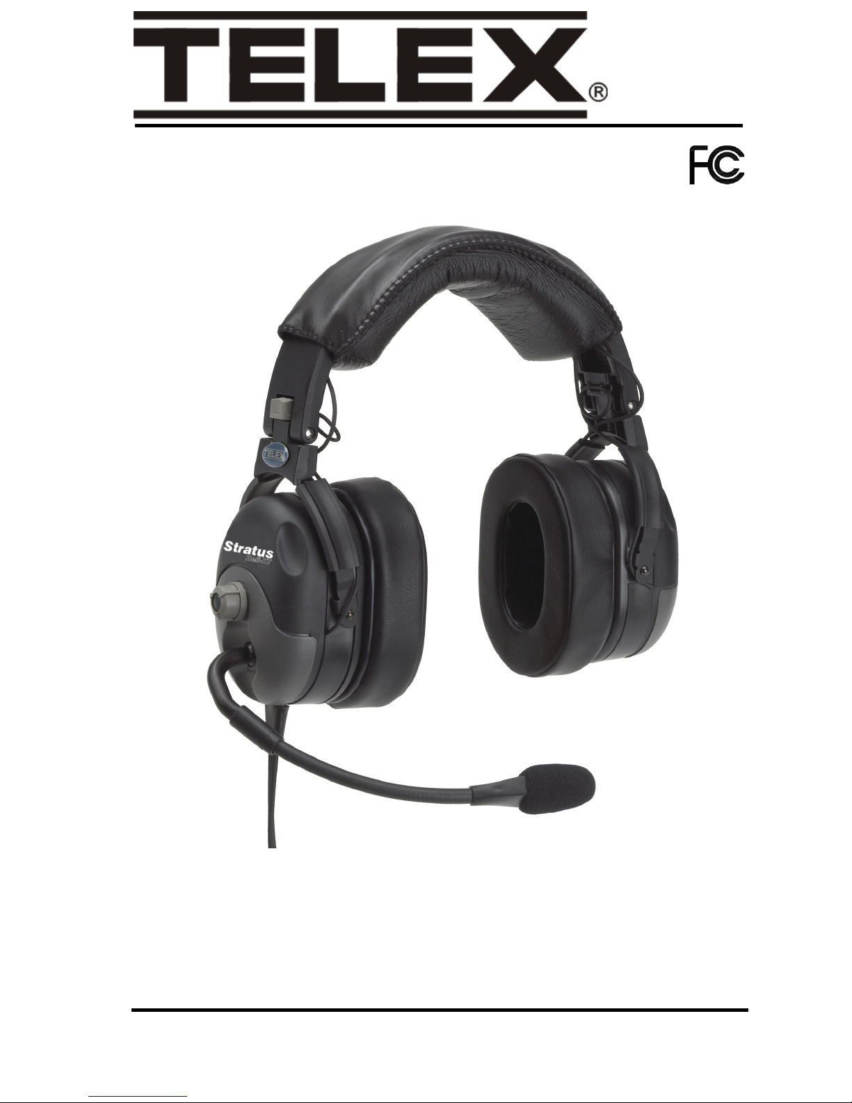
User Instructions
Stratus Heli-XT
Active Noise Reduction Headset
LIT000293000 Rev B 12/2008
Page 2

Uniform Limited Warranty
Telex branded products are warranted by
Telex Communications, Inc. against
malfunction due to defects in materials and
workmanship for a specified period, as noted
in the individual product line statements
below, beginning with the date of original
purchase by the end-user. if such
malfunction occurs during the specified
period, the product will be repaired with new
or remanufactured equivalent parts and
products or replaced (at our option) without
charge. The product will be returned to the
customer postage prepaid.
Exclusions and Limitations
The limited warranty does not apply to: (a)
exterior finish or appearance; (b) certain
specific items described in the individual
product line statements below; (c)
malfunction resulting from use or operation
of the product other than as specified in the
product data sheet or owner’s manual; (d)
malfunction resulting from misuse or abuse
of the product, including accidents; (e)
defects resulting from excess moisture,
lightening or power surges; or (f)
malfunction occurring at any time after
repairs have been made to the product by
anyone other than a Telex Service
Department employee or any of its
authorized service representatives. The
warranty is void if the label bearing the
product serial number (if applicable) has
been removed or defaced.
Other Express or Implied Warranties
Excluded
Limitation of Remedies; Certain
Damages Excluded
REPAIR OR REPLACEMENT OF
DEFECTIVE PRODUCTS ARE THE
SOLE AND EXCLUSIVE REMEDIES
PROVIDED BY TELEX TO THE
CUSTOMER OR TO ANY OTHER
PERSON AND SHALL CONSTITUTE
FULL SATISFACTION OF ALL CLAIMS,
WHETHER BASED ON CONTRACT,
NEGLIGENCE, STRICT LIABILITY OR
OTHERWISE. TELEX’S MAXIMUM
LIABILITY SHALL NOT EXCEED THE
ACTUAL PURCHASE PRICE PAID FOR
THE PRODUCT BY THE CUSTOMER.
TELEX AND ITS SUBSIDIARIES SHALL
NOT BE LIABLE FOR ANY INDIRECT,
INCIDENTAL, PUNITIVE, SPECIAL OR
CONSEQUENTIAL DAMAGES
INCLUDING, WITHOUT LIMITATION,
INJURY TO PERSONS OR PROPERTY
OR LOSS OF USE. SOME STATES AND
COUNTRIES DO NOT ALLOW THE
EXCLUSION OR LIMITATION OF
CERTAIN DAMAGES, SO THE ABOVE
LIMITATION OR EXCLUSION MAY NOT
APPLY TO YOU. IN SUCH STATES AND
COUNTRIES, TELEX SHALL BE LIABLE
FOR NO MORE THAN THE DIRECT
DAMAGES FOR BODILY INJURY AND/
OR REAL OR PERSONAL PROPERTY
ARISING FROM THE NEGLIGENCE OF
TELEX.
Other Rights
This warranty gives you specific legal rights,
and you may also have other rights,
depending upon where you live.
TO THE EXTENT PERMITTED BY
APPLICABLE LAW, THE WARRANTEID
SET FORTH HEREIN ARE IN LIEU OF,
AND EXCLUSIVE OF, ALL OTHER
WARRANTIES, EXPRESS OR IMPLIED.
SPECIFICALLYEXCLUDED, WITHOUT
LIMITATION, ARE THE WARRANTIES
OF MERCHANTABILITY, FITNESS FOR
USE OR FOR A PARTICULAR PURPOSE,
AND WARRANTIES ARISING FROM
COURSE OR DEALING OR USAGE OF
TRADE OR ANY OTHER MATTER. IF,
UNDER APPLICABLE LAW, IMPLIED
WARRANTIES MAY NOT BE VALIDLY
EXCLUDED, THE DURATION OF SUCH
IMPLIED WARRANTIES IS LIMITED TO
THE WARRANTY PERIOD.
Obtaining Warranty Service
To obtain warranty service, a customer must
deliver the product, prepaid, to the
appropriate Telex Service Department listed
below or any of its authorized service
representatives together with proof of
purchase of the product in the form of a bill
of sale or invoice.
Page 3

Applicable Law
Return equipment for factory repair to:
The validity, performance and construction of
this limited warranty shall be governed by the
laws of the State of Minnesota without
reference to its choice of law principles. The
Minnesota federal courts and/or the state courts
located in Hennepin County, Minnesota, shall
have exclusive personal and subject matter
jurisdiction over, and the parties shall each
submit to the jurisdiction of such courts and to
venue in Minnesota with respect to any dispute
concerning the product or pursuant to this
limited warranty, and all objections to such
jurisdiction or to such venue are hereby waived.
For additional warranty repair or service
information, contact the Telex Service
Department listed below:
USA, Canada, & Latin America
1720 E, 14th Street
Glencoe, MN 55336
Tel: 320-864-3177
Fax: 320-864-3225
Customer Service
Customer Service Department
Telex Communications, Inc.
1720 East 14th St.
Glencoe, MN 55336 U.S.A.
(320) 864-3177
Warranty Repairs
If in warranty, no charge will be made for the
repairs. Equipment being returned for warranty
repair must be sent prepaid and will be returned
prepaid.
Non-Warranty Repairs
Equipment that is not under warranty must be
sent postage prepaid to Telex. If requested, an
estimate of repair costs will be issued prior to
service. Once you approve repair, and repair of
equipment is completed, the equipment will be
returned on a collect on delivery basis. Collect
charges may be avoided by sending a signed
check for payment in full along with you signed
estimate approval form (the estimate includes
the shipping charge).
For information or technical assistance, call or
write Telex at:
Customer Service Department
Telex Communications, Inc.
12000 Portland Ave. So.
Burnsville, MN 55337 U.S.A
(952) 884-4051
www.telex.com/aircraft
When returning equipment for repair, please
enclose an explanation of the problem. And, if
the equipment is covered under warranty,
please enclose a copy of your proof of
purchase. The equipment must be accompanied
by documentation stating you name, return
address, and telephone number.
Aviat io n
Stratus Heli-XT X
** Warranty subject to change without notice.
Telex Warranty Term Lengths
1 Month 3 Months
12
Months
36
Months
60
Months Other
Page 4

Ordering Information
Stratus Heli-XT Headset.......................................................................PRD000220000
Stratus Heli-XT 1” Replacement Foam-Filled
Ear Cushions (package of 2)........................................................................ 800456021
Stratus Heli-XT Premium Replacement Headband Pad.............................. 800456017
Replacement Electret Microphone .............................................................. 800136100
Microphone Windscreen.............................................................................. 800456000
Clothing Clip ............................................................................................... 590637000
Stratus Heli-XT Replacement Carrying Case......................................CME000009000
Cell Phone Accessory Cable ....................................................................... 550216002
Auxiliary Device Accessory Cable ............................................................. 550216003
Aircraft Power Cord .................................................................................... 550216004
AC Wall Adapter ....................................................................................... 8004546023
Battery Box Door ........................................................................................ 800456024
Page 5

Table
of
Contents
Design Features ...............................................................................4
Auto Shut-Off .................................................................................6
Battery/User Interface Module .......................................................6
Electrical Requirements ..................................................................6
Microphone Bias Voltage ...............................................................6
Headset Power ................................................................................6
Wiring Diagram ..............................................................................7
Specifications ..................................................................................8
Headset Operation ...........................................................................9
Headband Size Adjustment .............................................................9
Headband Pressure Adjustment ....................................................10
Microphone Boom Rotation .........................................................12
Microphone Placement .................................................................12
Battery Installation ........................................................................13
Accessory Connections .................................................................13
Speaker Volume Adjustment ........................................................14
Powering ON/OFF ........................................................................14
Accessory Muting .........................................................................15
Battery Charging ...........................................................................15
Disable Auto Shut-Off ..................................................................15
Reading the LED Indicator ...........................................................16
Microphone Gain Adjustment ......................................................16
Microphone Replacement .............................................................17
Ear Cushion Replacement .............................................................18
Notes .............................................................................................19
Page 6

Page 7

CHAPTER 1
Introduction
Introduction 3
Page 8
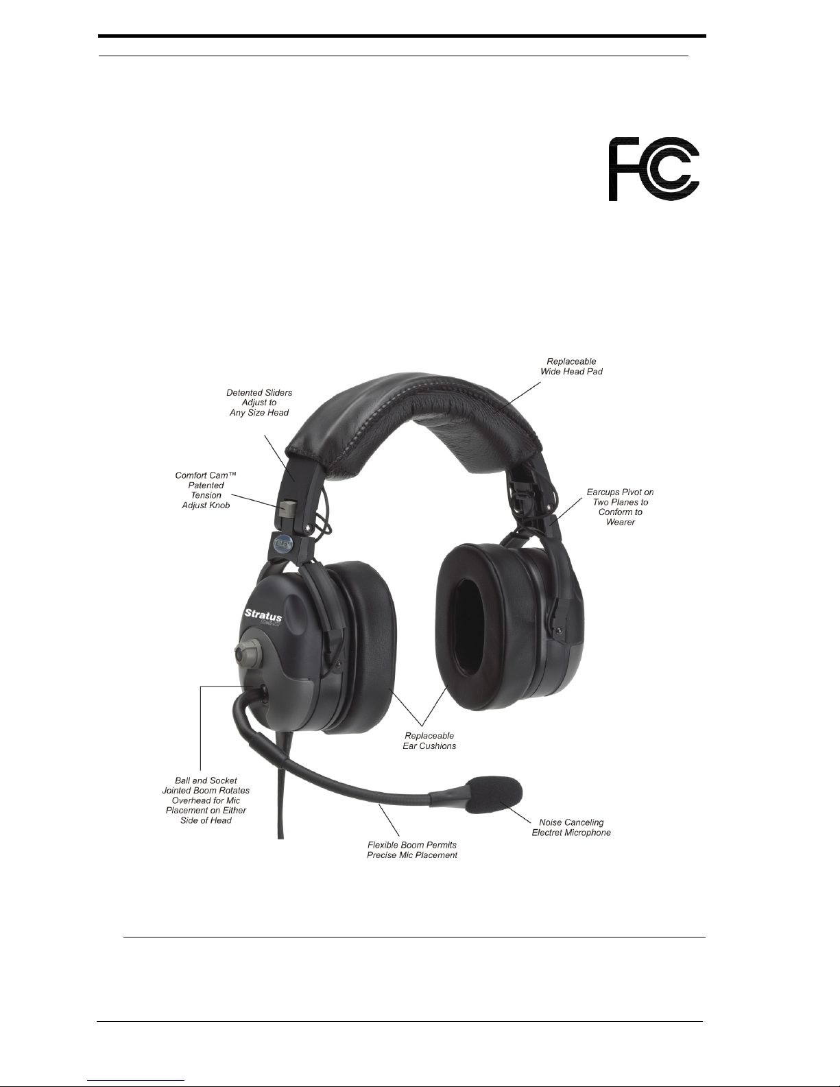
Design Features
NOTE: This device complies with part 15 of the FCC Rules.
Operation is subject to the following two(2)
conditions:
1.This device may not cause harmful
interference.
2.This device must accept any interference
received, including interference that may
cause undesired operation.
FIGURE 1. Stratus Heli-XT Reference View
4 Introduction
Page 9

Noise Reduction Passive noise reduction: >29dB
Active noise reduction: up to 16dB
Fit and Comfort Detented slide adjustment on the headband allows the ear cup
to be easily raised or lowered for proper fit. Yoke design allows
the ear cup to pivot in two planes assuring proper seal to the
head and distributing ear cushion pressure evenly over its entire
surface. Adjust ear cup pressure by rotating the patented
“Comfort Cam™” to one of three(3) tension settings.
1” thick ear cushion made from heat sensitive slow recovery
foams Conforms to your head to provide a perfect seal while
spreading the weight over a large area eliminating pressure
points.
Boom
Microphone
Cordage and
Plugs
Amplified electret noise-canceling microphone prevents
unwanted cabin noise from entering the communication system.
Boom rotates up to allow the boom to be worn on the left or
right side. Retaining hooks are designed into the microphone
housing to securely hold the windscreen in place and prevent it
from slipping off.
All cables are shielded to protect against RFI (Radio Frequency
Interference). Strain relief is added to all cord entry points to
provide protection from tugging resulting from normal usage.
Bend relief is added at high-flex cord entry points to protect
cords from breakage due to bending.
• Cable with 2.5mm plugs is provided for interfacing to a
cellular telephone.
• Cable with 3.5mm plugs is provided for interfacing to a
portable music device, such as a CD player or MP3 player.
Cigarette lighter adapter is provided to power the headset off of
aircraft power and to recharge the batteries.
AC wall adapter is provided to recharge the batteries when user
is away from the aircraft.
Introduction 5
Page 10

Auto Shut-Off
Headset will shut off automatically after 15 minutes in low-noise environments.
When Auto Shut-off is enabled, audio signals that keeps the headset active are:
• communication over the aircraft radio/intercom system
• cellular phone conversations
• listening to music
• cabin noise greater than 90dB SPL
Battery/User Interface Module
Puts most commonly used controls at the pilot’s fingertips. Cell phone jack for
communication on your cell phone using the headset microphone and speakers.
Auxiliary input jack for listening to portable CD and MP3 players using the headset
speakers. Power ON/OFF button turns ON and OFF all function to and from the
headset except for to and from the radio/intercom system. Accessory mute button
quickly and completely disables the cell phone and auxiliary audio devices, while
maintaining radio/intercom communication. LED indicates power ON/OFF,
accessory enabled/muted, low battery and battery charging. CD input jack to power
the headset OFF of aircraft power and to recharge the batteries.
Electrical Requirements
Microphone Bias Voltage
8-16VDC. Output is designed for radio input impedances from 50-600 Ohms.
Headset Power
2AA Alkaline or NiMH batteries or panel power from 8-32VDC negative ground
electrical systems.
6 Introduction
Page 11
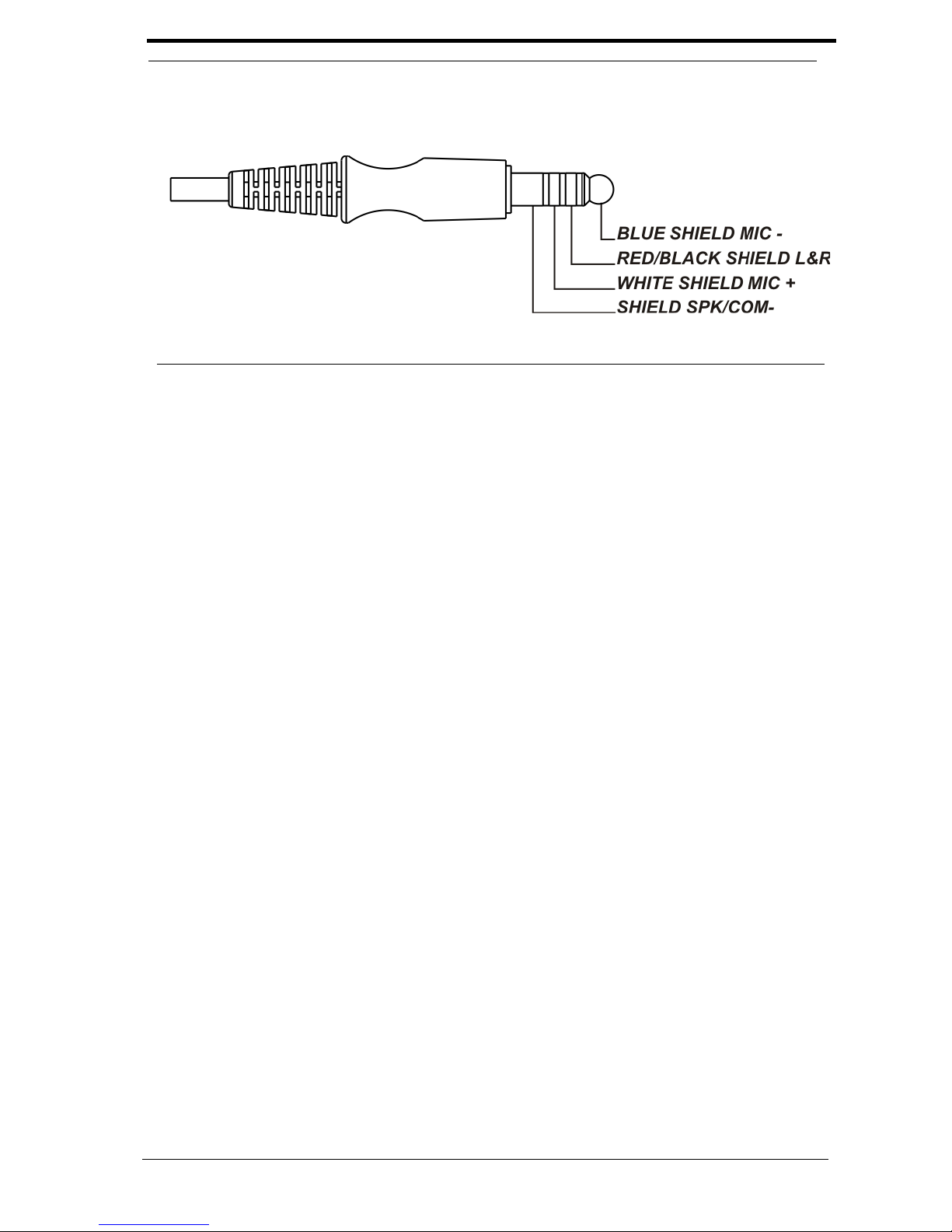
Wiring Diagram
FIGURE 2. Wiring Diagram
Introduction 7
Page 12

Specifications
Receivers
Type:
Dynamic
Frequency Response:
50Hz - 10kHz
Sensitivity:
95±5dB SPL (1kHz, 1mW input)
Impedance (Max. Volume):
Monaural, 150 Ohms
Headset Power:
2 - AA batteries or panel power from 8-32 Vdc
Microphone
Element Type:
Amplified noise-canceling electret
Frequency Response:
100Hz - 3.5kHz
Sensitivity:
-50 ±6dB (ref: 1V/μbar at 1kHz with 12Vdc supply voltage and 470 Ohm DC, 150
Ohm AC load)
Matching Impedance:
50 - 600 Ohms
Gain Adjustment Range:
±5dB (clockwise rotation increases gain; counterclockwise rotation decreases gain)
Operating Voltage:
8-16Vdc (supplied by aircraft radio/intercom)
Cordage
Coiled Cord 8.5 ft. (2.6m) extended
Connectors
Microphone and Receiver Plug:
U174u equivalent TP120
2.5mm 3 conductor audio jack for connection to cell phone connection
3.5mm 3 conductor audio jack for connection to auxiliary audio
DC Jack:
1.3mm ID, 3.5mm OD, pin +
Weight
Effective Head Weight:
Approximately 18.5oz. (524g)
Color
Grey/Black
8 Introduction
Page 13

CHAPTER 2
Operation
Headset Operation
Headband Size Adjustment
To adjust the headband size, do the following:
1. With the headband resting securely on the top of the head, verify the ear
cups are centered over the ears.
Operation 9
Page 14
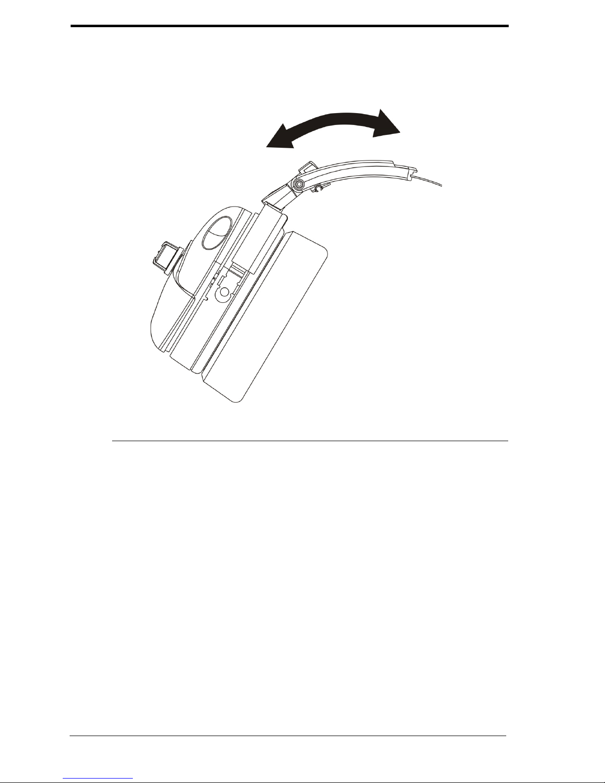
2. Reposition the ear cups, if necessary, by moving the headband sliders up or
down.
FIGURE 1. Headband Size Adjustment
Headband Pressure Adjustment
There are three(3) pressure settings. Increasing the pressure improves the seal
between the ear cup and the head for greater noise reduction.
To change the pressure setting, do the following:
1. Remove the headset and fold the ear cup inward.
2. Rotate the Comfort Cam™ to the desired setting.
3. Repeat for both ear cups.
NOTE: Both sides of the headband should be set to the same
pressure setting to keep the headband properly centered on
the head.
10 Operation
Page 15
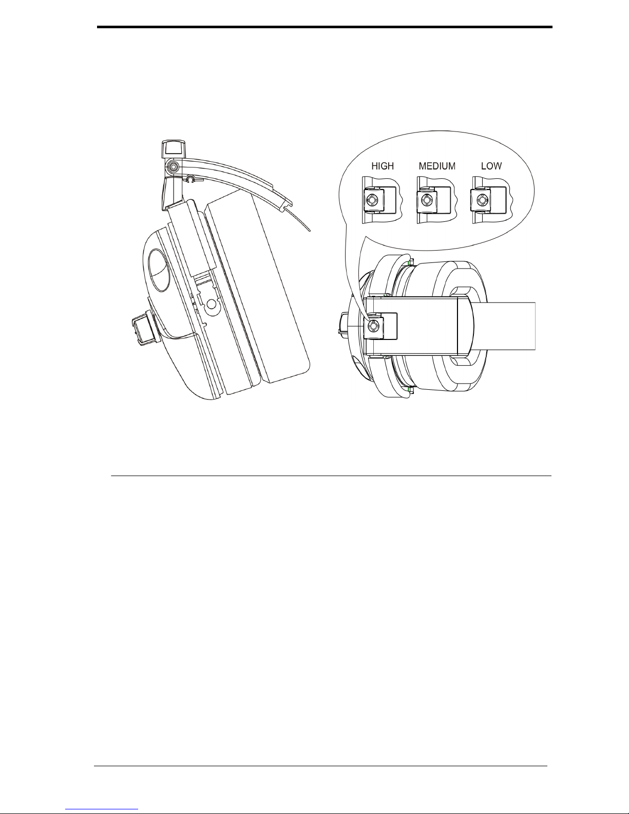
FIGURE 2. Headband Pressure Adjustment
Side View
Top Vi ew
COMFORT CAM™ ADJUSTMENT SETTINGS
Operation 11
Page 16
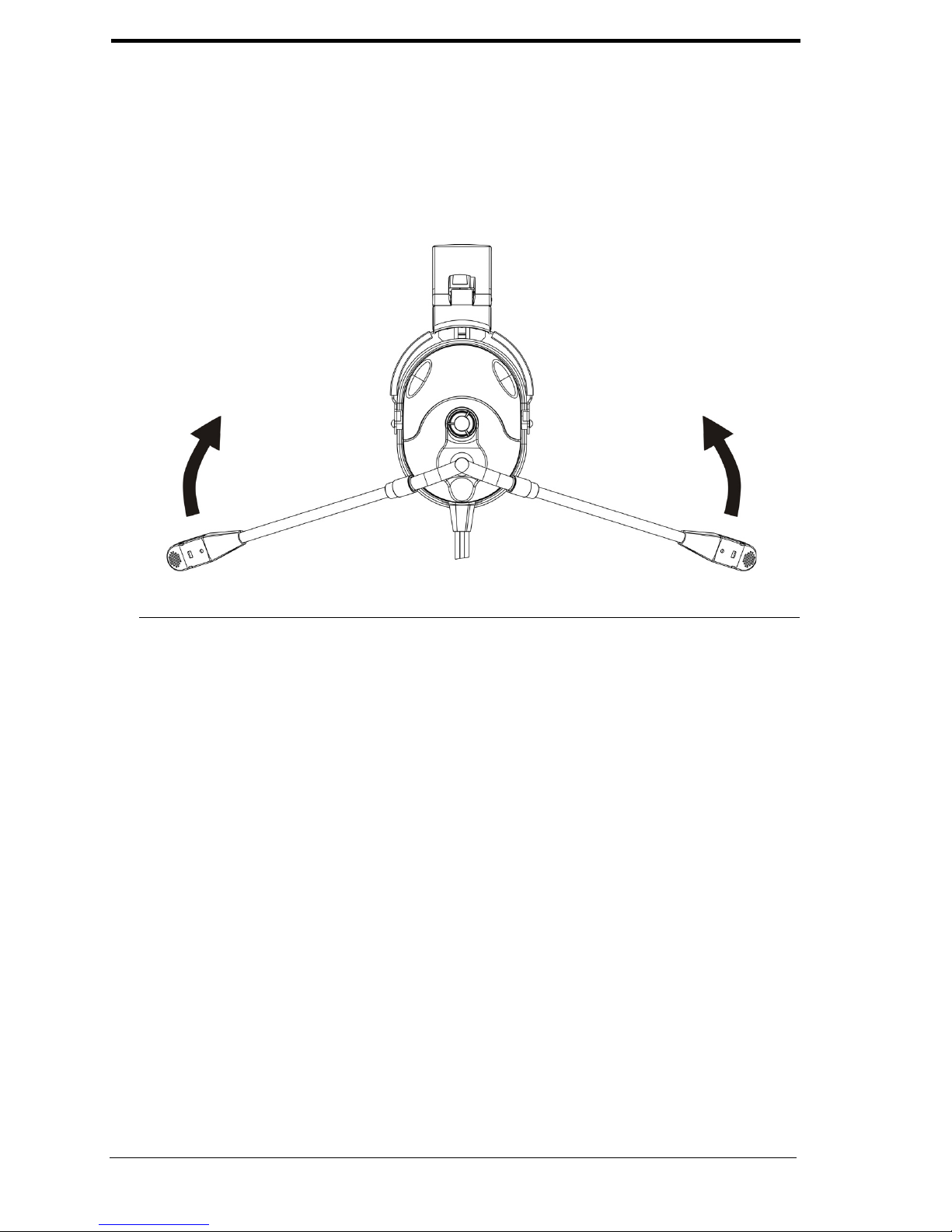
Microphone Boom Rotation
To rotate the boom microphone, do the following:
> Rotate the entire boom overhead to wear the microphone on either the right
or left side of the head.
FIGURE 3. Microphone Boom Rotation
Microphone Placement
To accurately place the microphone, do the following:
> Reshape the boom so the microphone is in front of the mouth.
NOTE: To assure optimal performance, the user should position
the microphone close to the lips as possible, near the
corner of the mouth with the flat part of the microphone
parallel to the user’s face. Speak in a normal voice.
12 Operation
Page 17
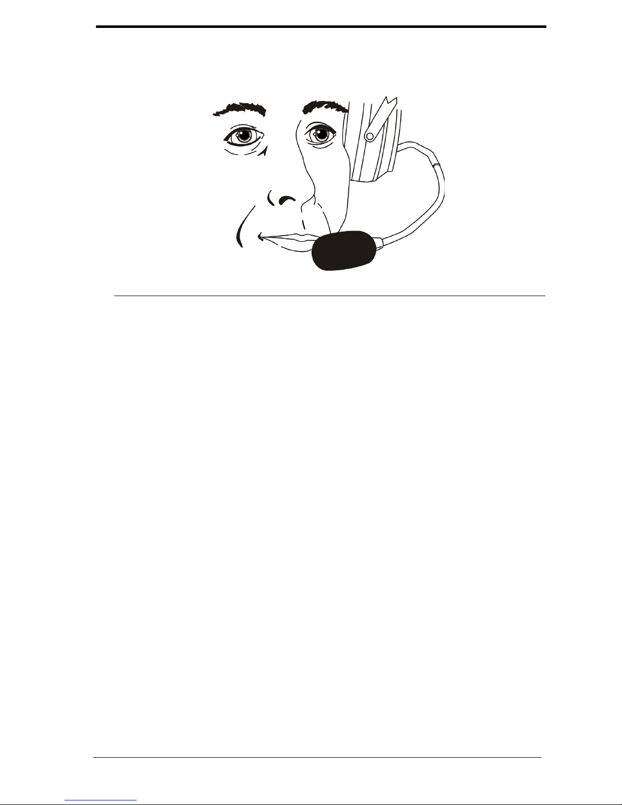
FIGURE 4. Mic Placement
Battery Installation
NOTE: Rechargeable NiMH Batteries supplied with the Stratus Heli-XT need to
be fully charged before first use.
To install the batteries, do the following:
1. Press the thumb-grip area of the battery cover and slide the battery cover
down, and then lift off the cover.
2. Place the batteries into the battery compartment in the direction indicated.
3. Slide the battery cover back into place.
Accessory Connections
Connect cellular telephone and/or audio input devices, as desired.
The Telex Stratus Heli-XT cell phone/audio interface has been designed to function
with the widest array of cellular telephones and portable audio devices. There are cell
phones and audio devices on the market not designed to industry physical and
electrical standards. These devices are not guaranteed to function properly with the
Stratus Heli-XT headset.
See the Telex website (www.telex.com/aircraft), for additional information.
Operation 13
Page 18
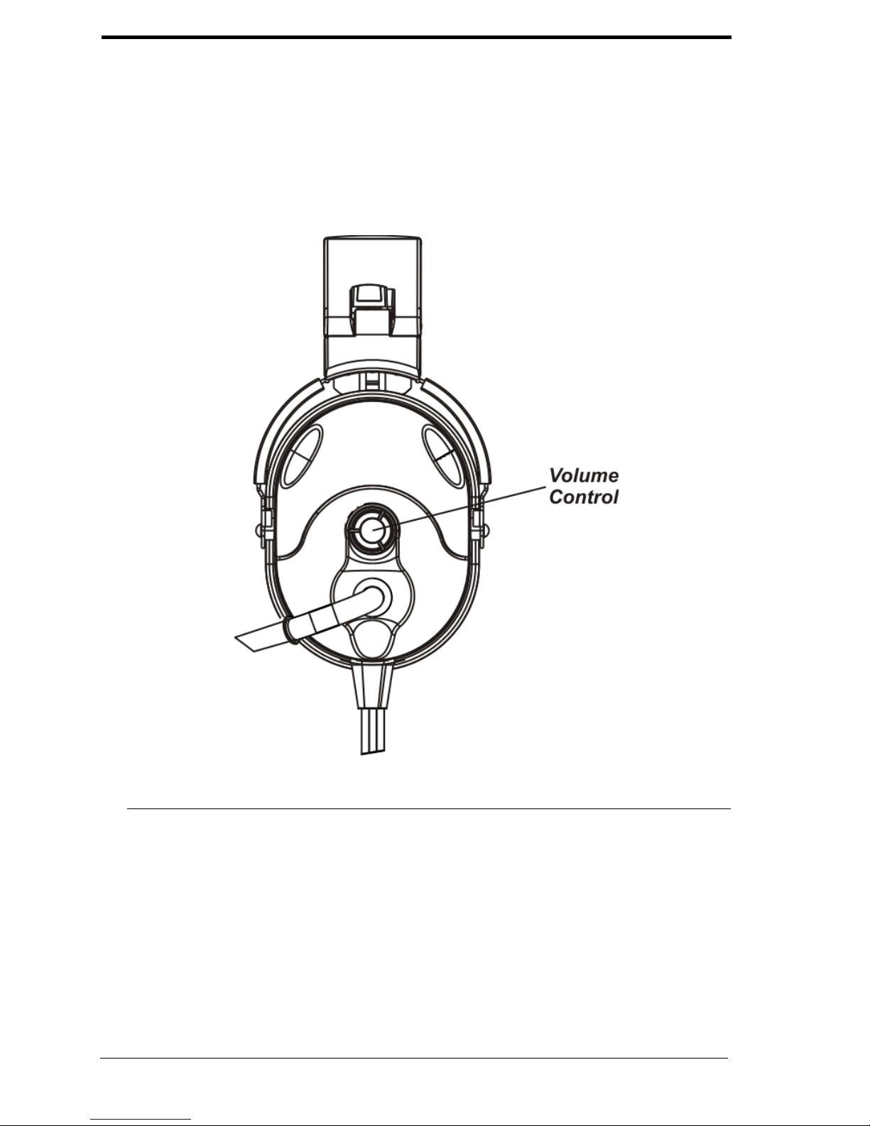
Speaker Volume Adjustment
When the microphone is worn on the left side, volume is increased by rotating the top
of the volume controls toward the front of the head. Control operation is reversed
when the microphone is worn on the right side. Volume control affects
communications, as well as cell phone and auxiliary audio inputs.
FIGURE 5. Volume Adjustment
Powering ON/OFF
To power the headset ON, do the following:
> To turn the headset ON, press the ON/OFF button.
A blinking LED indicates the power is ON.
To power the headset OFF, do the following:
14 Operat ion
Page 19

> To turn the headset OFF, hold down the ON/OFF button until the LED
blinks rapidly, and then let go.
The blinking LED stops when the unit is OFF.
Accessory Muting
To mute accessories, do the following:
> To either enable or mute the accessories, press the accessory mute button.
When the accessories are muted, the LED blinks at a slower rate than when
they are enabled.
Battery Charging
To charge the batteries, do the following:
> Connect either the AC wall adapter or the aircraft cigarette lighter to the
DC input jack.
If the headset is OFF, the LED lights solid red during charging. If the unit is
ON and the batteries are charging, the LED will be mostly ON, but blink
OFF occasionally, as opposed to being mostly OFF but blinking ON
occasionally when the batteries are not charging.
Disable Auto Shut-Off
To disable the auto shut-off feature, do the following:
1. Remove the batteries from the unit (see “Battery Installation” on page 13).
2. Locate the DIP switch in the battery compartment.
3. Using a small, flat-blade screwdriver, set switch position 3 to the ON
position (away from the number 3.
Auto Shut-Off can be re-enabled by setting switch 3 to the OFF position
(toward the number 3).
Operation 15
Page 20

Reading the LED Indicator
TABL E 1 . LED Indicator Descriptions
Battery
Normal
Battery Low Battery Charging
Power OFF LED OFF LED OFF LED Solid Red
Power ON/
Accessories
Enabled
Power ON/
Accessories
Muted
Blinks
Green every
two (2)
seconds
Blinks
Green every
four (4)
seconds
Blinks Red
every two (2)
seconds
Blinks Red
every four (4)
seconds
Blinks OFF every two (2)
seconds
Blinks OFF every four (4)
seconds
Microphone Gain Adjustment
The microphone gain has been factory-adjusted to the nominal level required for
aviation use, and should not require adjustment. Any changes to the microphone gain
should be done by a qualified avionics technician.
To access the gain trimmer, do the following:
1. Insert a small, flat-blade screwdriver through the access hole in the
microphone assembly.
2. Turn the gain pot clockwise to increase the gain.
OR
Turn the gain pot counterclockwise to decrease the gain.
16 Operation
Page 21
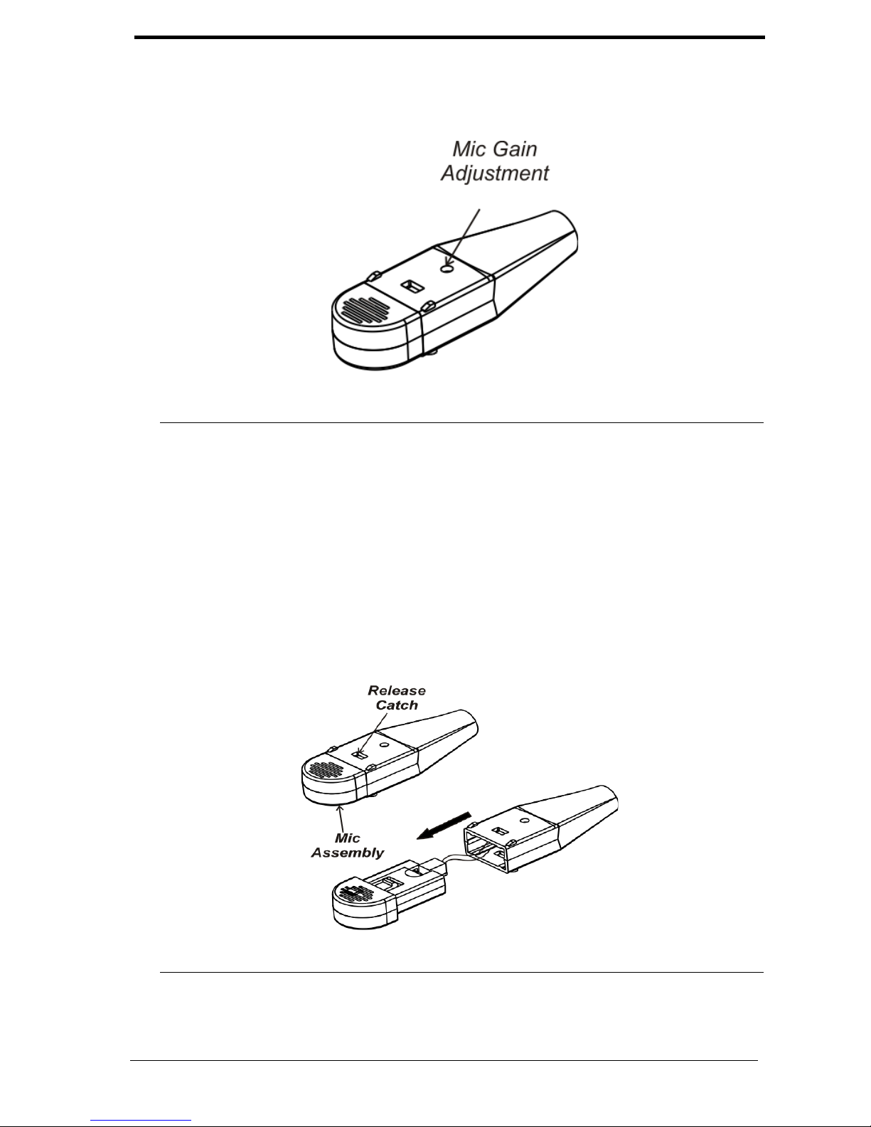
FIGURE 6. Microphone Gain Adjustment
Microphone Replacement
To replace the microphone, do the following:
1. On the boom assembly, press the release catch and carefully pull the
microphone from the mic mount.
Be sure not to pull the connecting wires from the mic mount.
2. Detach the microphone from the connector.
FIGURE 7. Mic Element Removal
Operation 17
Page 22

3. Re-attach the new microphone to the connector.
4. Carefully rejoin the microphone and microphone mount, taking care not to
fold the connecting wires.
Ear Cushion Replacement
To remove an old ear cushion, do the following:
> Grasp the ear cushion and pull it off the ear cup.
To install a new ear cushion, do the following:
1. Starting at the top of the ear cup, place the back flap of the ear cushion over
the top lip of the ear cup.
2. Pull the bottom of the ear cushion over the bottom lip of the ear cup.
18 Operation
Page 23

Notes
Operation 19
Page 24

TELEX COMMUNICATIONS, INC. • 12000 PORTLAND AVE S., BURNSVILLE, MN 55337 U.S.A
 Loading...