

Page 1
®
Telex
User Instructions
Listen
Call
Headset
Talk
Panel Mic
Ch Select
GRN 1
RED 2
Headset
Volume
Panel Mic
TM
SS2000
SS2000
Listen
Call
Headset
Talk
Panel Mic
Ch Select
GRN 1
RED 2
Headset
Volume
Panel Mic
TM
SS2000 “S” Box
SS2000
Headset
GRN 1
Panel Mic
RED 2
Ch Select
Listen
Call
Talk
Volume
TM
Headset
Panel Mic
SS2000 “P” Box
SS2000 “U” Box
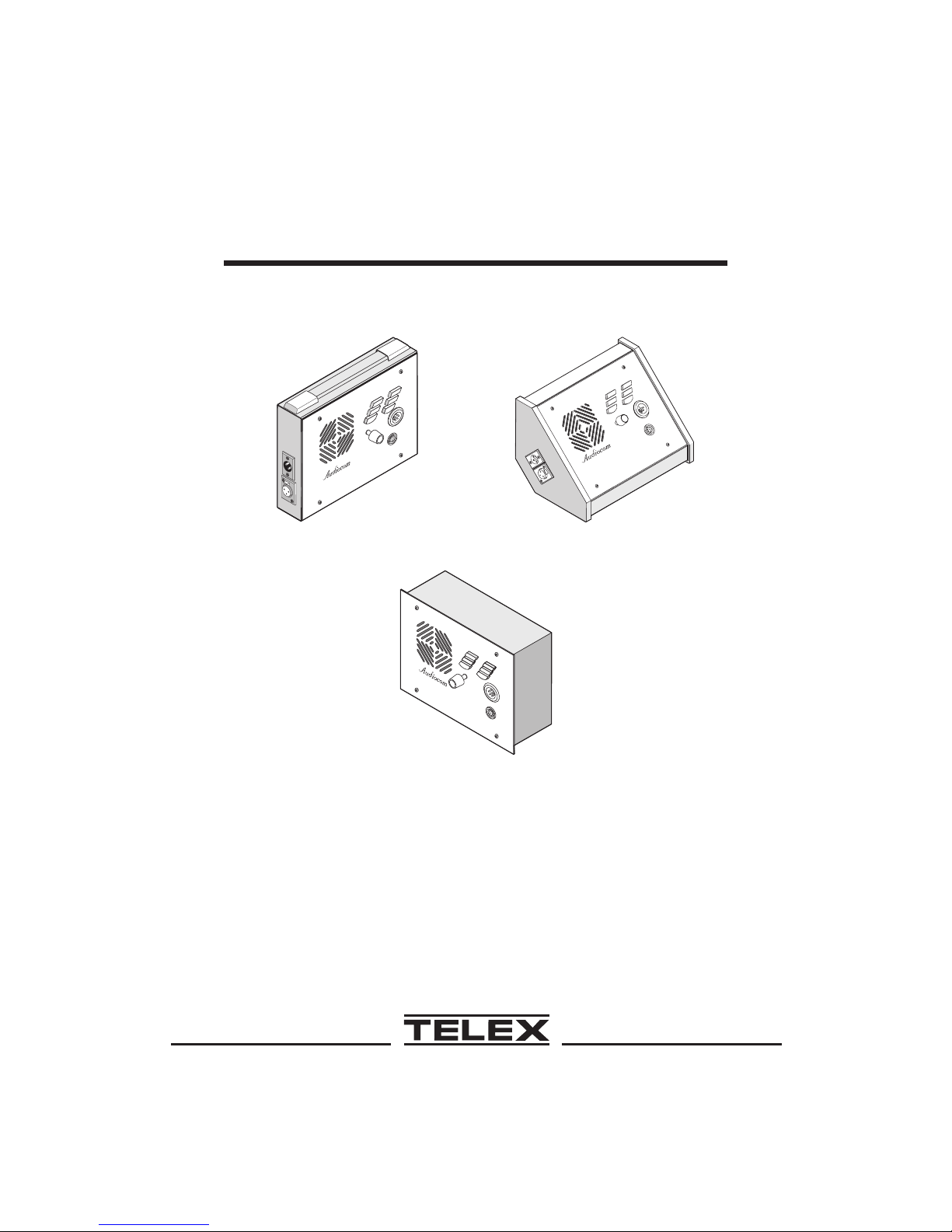
Model SS1000 / SS2000
Intercom Speaker Stations
®
Audiocom
Intercom Systems
®
Page 2

FCC Statement
This equipment uses and can radiate radio frequency energy that may cause interference to radio communications if not installed in accordance with this manual. The equipment has been tested and found to comply with the limits of a
Class A computing device pursuant to Subpart J, Part 15 of FCC Rules which
are designed to provide reasonable protection against such interference when operated in a commercial environment. Operation of this equipment in a residential
area may cause interference which the user (at his own expense) will be required
to correct.
This productmeets Electromagnetic Compatibility Directive 89/336/EEC.
Introduction.
Thank you for purchasing the Audiocom SS1000 / SS2000 Intercom Speaker
Station. We hope the many design features of this product will satisfy your intercommunication requirements for many years to come. To get the most out of
your new intercom station, please take a few moments to look through this booklet before using the Intercom Speaker Station for the first time.
2
Page 3

Table of Contents
Description .............4
Features ..............5
Installation .............8
Unpacking ............8
Configuration Pre-check..........8
Intercom Channel Connections ........11
Headset / Headphone / Microphone Connections ....19
Power-Up ............20
Sidetone Adjustment ..........20
Operation .............22
Channel Select (SS2000 Only) ........22
Headset / Headphone / Speaker / Microphone Selection . . 22
Receiving Calls ...........22
Calling an Intercom Channel ........22
Specifications ............24
Factory Service and Parts Information .......26
3
Page 4
Audiocom®
Description
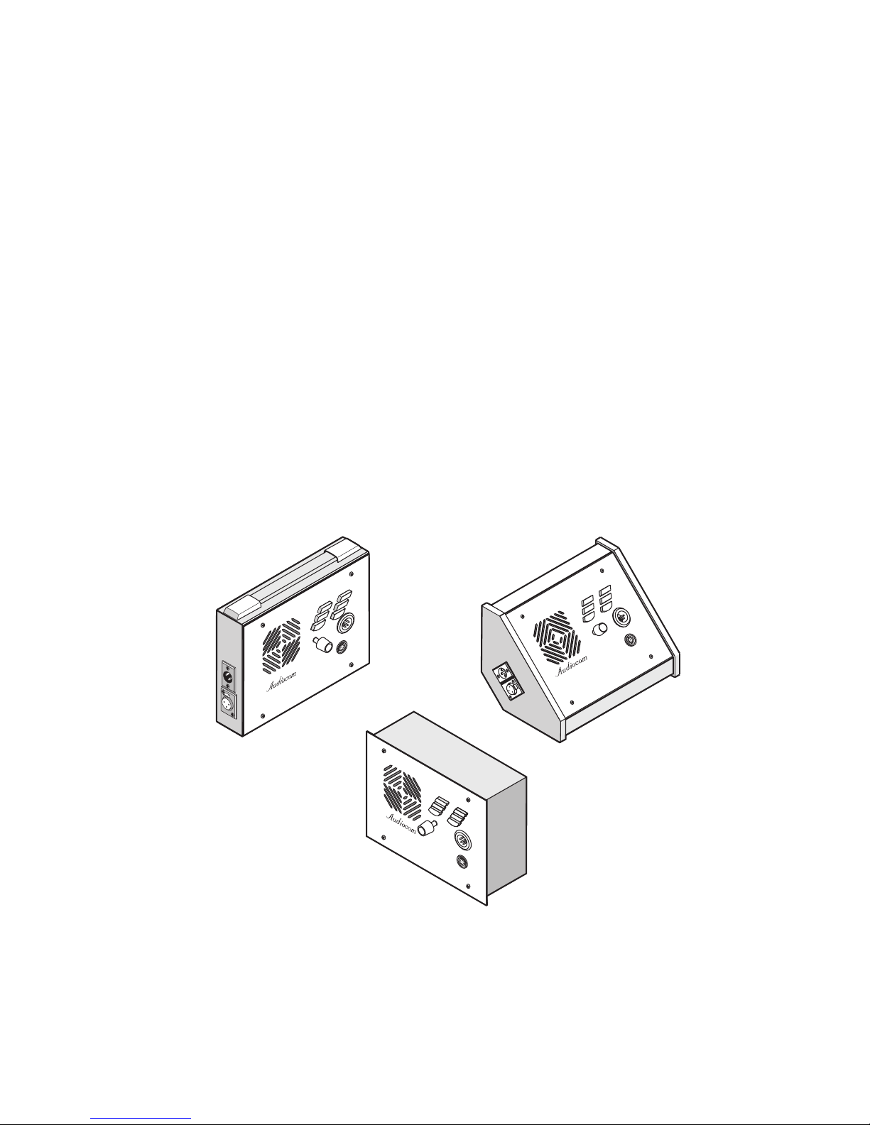
The SS1000 and SS2000 Intercom Speaker Stations may be used with a headset, or
with the built-in speaker and an optional gooseneck panel microphone, or with head-
phones and an optional gooseneck microphone. As an alternative to a headset, a tele-
phone style handset may also be used. The SS1000 is a single-channel station; the
SS2000 provides switch-selectable access to either of two intercom channels. Both
the SS1000 and SS2000 come in three versions to suit a variety of applications. The
“S” box is a portable version. It has a carrying handle and dual “loop-through” inter-
com connectors which permit stations to be quickly interconnected using prefabri-
cated cables. The “P” box is a stationary version. It also has dual “loop-through”
connectors for quick interconnection, but the case is designed for desktop or
console-mount applications. The “U” box is designed for permanent, in-the-wall
mounting. It uses quick release terminals for connection to the intercom system.
Listen
Call
Headset
Talk
Panel Mic
Ch Select
GRN 1
RED 2
Headset
Volume
Panel Mic
TM
SS2000
“S”Box
“U”Box
SS2000
Headset
GRN 1
Panel Mic
RED 2
Ch Select
Listen
Call
Talk
Volume
TM
Headset
Panel Mic
Figure 1. Speaker station versions (SS2000 shown.)
4
SS2000
GRN 1
RED 2
Headset
Panel Mic
Ch Select
TM
Listen
Call
Talk
Volume
“P”Box
Headset
Panel Mic
Page 5

Features
1. Channel and Power Connections: The "U" box uses quick release terminals to connect au-
dio and power wires. For the “S” box and “P” box versions, the terminal connections are
brought out to the dual, loop-thru XLR connectors on the side of the box. These permit
several stations to be connected in a string, or daisy-chain, using prefabricated intercom
cables.
2. Configuration DIP switches: These switches control the following features:
Call Beep: In addition to a flashing call key indication for incoming calls, an incoming
call beep tone can also be used.
Headset Microphone Type Selection: Either a balanced or unbalanced dynamic microphone may be selected.
DC call enable: This may be turned on to use the intercom station with intercom systems that use DC call signaling.
3. Panel Mic Key: Selects the Panel Mic connector (11) in the on position and the Headset
connector (10) in the off position.
4. Speaker Key: Selects the built-in speaker in the on position and the Headset connector
(10) in the off position.
5. Channel Select Key (SS2000 Only): Selects intercom channel 1 or 2. The key lights green
for channel 1 and red for channel 2.
6. Volume Control: Adjusts intercom listen volume to headphones or speaker.
7. Intercom Listen Key: Both momentary (push-to-listen) and latching (hands-free listen)
are possible.
8. Call Key: Used to send call signals on the intercom channel. Flashes for incoming calls.
9. Intercom Talk Key: Both momentary (push-to-talk) and latching (hands-free talk) are pos-
sible. The SS1000 / SS2000 also features a "mic kill receive" circuit, which allows an op-
erator at a remote master station (such as the US2000A) to turn off the SS1000 / SS2000
talk key.
10. Dynamic-Mic Headset Connector: 4-pin male XLR connector accepts headsets with mon-
aural headphones and either a balanced or unbalanced dynamic microphone. Also accepts
a telephone style handset. Can also be used with headphones when a Panel Mic is con-
nected. Or, can be used with a handheld microphone along with the internal speaker.
11. Panel Mic / Electret-mic Headset Connector: Accepts an electret gooseneck microphone,
such as the Telex Model EGM-12N or EGM-18N.
12. Sidetone Trimmers: These adjust the level of the user's own voice in the headphones
when using full-cushion headphones. (Eliminates the muffled sensation when talking
with the ears completely covered.) When using the speaker or open-ear style headphones,
the sidetone trimmers are adjusted to eliminate the user's voice from the headphones or
speaker. This helps to prevent feedback.
5
Page 6
Audiocom®
13. Balanced / Unbalanced Selector Switch: This switch sets the intercom station for compatibility with either Audiocom or Clear-Com* intercom systems.
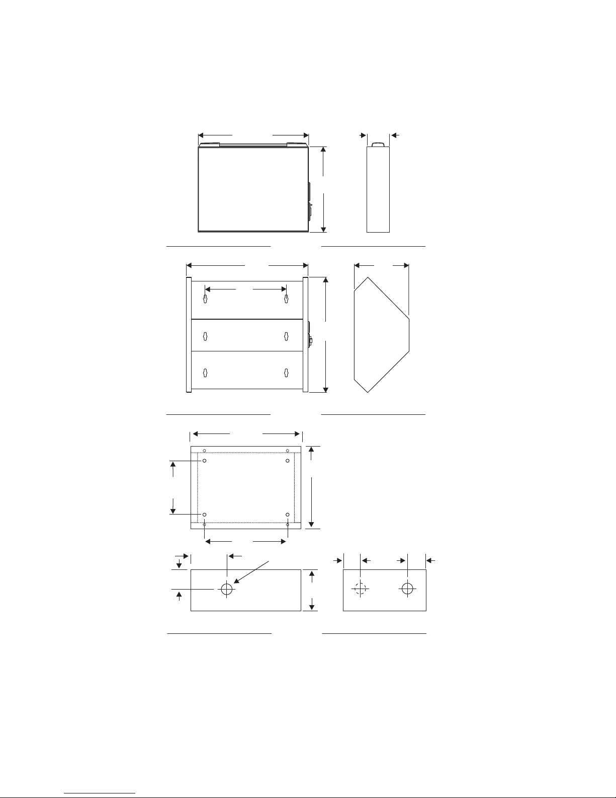
14. Mounting Holes (Figure 3
boxes may be mounted on a wall, desktop, or console.
): The “U” box is typically mounted in a wall. The “S” and “P”
TOPVIEW OF
FACEPLATE
3
4
5
6
SS2000
1
2
1
Listen
Panel Mic
Speaker
Ch Select
Call
Talk
Headset
Panel Mic
GRN 1
RED 2
Volume
TM
7
8
9
10
11
Ch 1
12
Ch 2
SW1
BACK SIDE OF
13
FACEPLATE
1
Listen
Call
Headset
Talk
SS2000
Panel Mic
Ch Select
GRN 1
RED 2
Headset
Volume
Panel Mic
TM
SS2000
Listen
Call
Headset
Talk
Panel Mic
Ch Select
GRN 1
RED 2
Headset
Volume
Panel Mic
TM
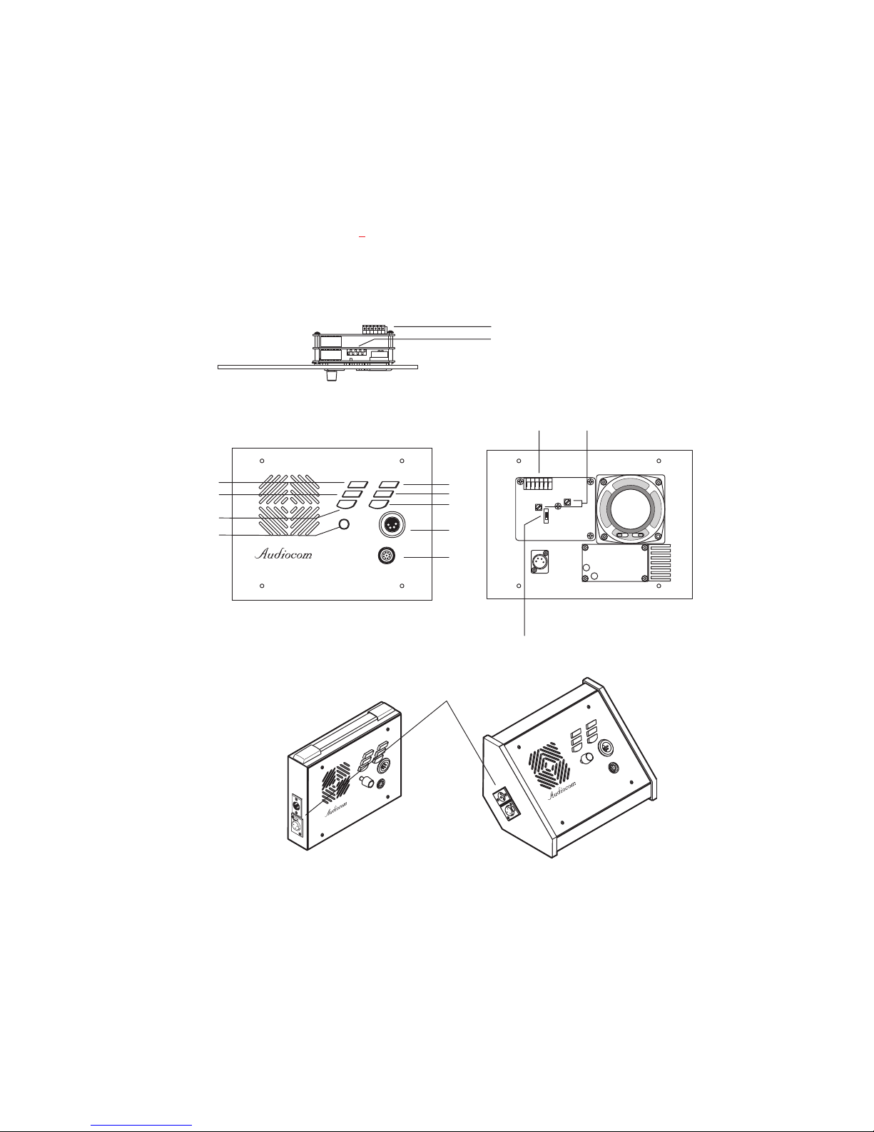
Figure 2. Reference view for controls, indicators and configuration switches. (The
numbered items refer to the features list.)
* Brand names mentioned are the property of their respective companies.
6
Page 7
9.125“
231.78 mm
9.625
244.48 mm
6.102
155.0 mm
8.11"
206 mm
"S" Box
"
"P" Box
6.75"
171.5 mm
8.563"
217.5 mm
2.125“
53.98 mm
4.125"
104.78 mm
3.937"
100 mm
2.7"
69 mm
1.575"
40 mm
Figure 3. Dimensions
6.102"
155 mm
6.102"
155 mm
.812" Dia (3 Places)
20.63 mm
3.15“
80 mm
"U" Box
1.56"
39.6 mm
1.56"
39.6 mm
7
Page 8

Audiocom®
Installation
Unpacking
Each SS1000 / SS2000 is supplied with the following items. Contact the shipper or
your Audiocom dealer immediately if anything is damaged or missing. Detach and
fill out the registration card and return it to Telex to properly register your intercom
station.
Quantity Description
1 SS1000 or SS2000 Intercom Station
1 Warranty and registration card
1 User Instructions
Configuration Pre-check
Before making connections, read the configuration notes that follow, and make sure
that all internal controls are properly set for your intended usage. If you need to access the internal controls, remove the four screws on the front that secure the intercom station faceplate to the mounting box, then lift out the faceplate. Figure 2 shows
the locations of the internal controls.
DIP Switches (Figure 2, item 2)
Table 1
lists the DIP switch descriptions and factory default settings.
DC Call Enable (DIP Switch 2)
For Audiocom setup, leave this switch in the open position, and also leave the Balanced / Unbalanced switch (Figure 2, item 13) in the Balanced position. For
Clear-Com setup, set DIP switch 2 to the closed position and set the Balanced / Unbalanced switch in the Unbalanced position.
8
Page 9

Table 1. DIP Switch Settings
Switch
Number
1 Not used Don't care Open
2 Call signal method
3 Incoming call beep
4 Microphone type
5
6 Not used Don’t care Open
7 Not used Don’t’ care Open
8 Not used Don’t care Open
Description Settings
Open=Off, Closed=On
Closed: DC (SW1 set to UNBAL)
Open: Audiocom (SW1 set to BAL)
Closed: Disabled
Open: Enabled
Closed: Unbalanced
Open: Balanced
Speaker beep for
incoming call
Closed: Enabled (DIP switch 3 must
be set to Open)
Open: Disabled
Default
Setting
Open
Open
Open
Open
Incoming Call Beep (DIP Switch 3)
Incoming calls are always indicated by a red-flashing call key. If you also want incoming call beep in headphones, set DIP switch 3 to the Open position (default). DIP
switch 3 must also be in the Open position if you want to activate incoming call beep
to the speaker using DIP switch 5.
Dynamic Microphone Type Selection (DIP Switch 4)
If you will be using a headset, telephone-style handset, or dynamic handheld
microphone, and the specifications indicate the microphone type is balanced, leave
DIP switch 4 in the Open (default) position. If the specifications indicate an unbalanced microphone set this switch to the Closed position. If you are not sure, leave the
switch in the Open position for now, then try both positions during operation. Use the
position that produces the best audio quality at other stations.
9
Page 10

Audiocom®
Speaker Beep for Incoming Call (DIP 5)
Set DIP switch 5 to the Closed position if you want to hear incoming call beep in the
speaker. Note that DIP switch 3 must be in the Open position.
Balanced/Unbalanced Switch (Figure 2, item 13)
This switch is set at the factory to the Balanced, or BAL, position for use with
Audiocom intercom channels. Set the switch to the Unbalanced, or UNBAL, position
for use with a Clear-Com intercom system.
Sidetone Trimmers (Figure 2
These are normally adjusted after all connections are completed. See "Sidetone Adjustment", page 20.
, item 12)
10
Page 11

Intercom Channel Connections
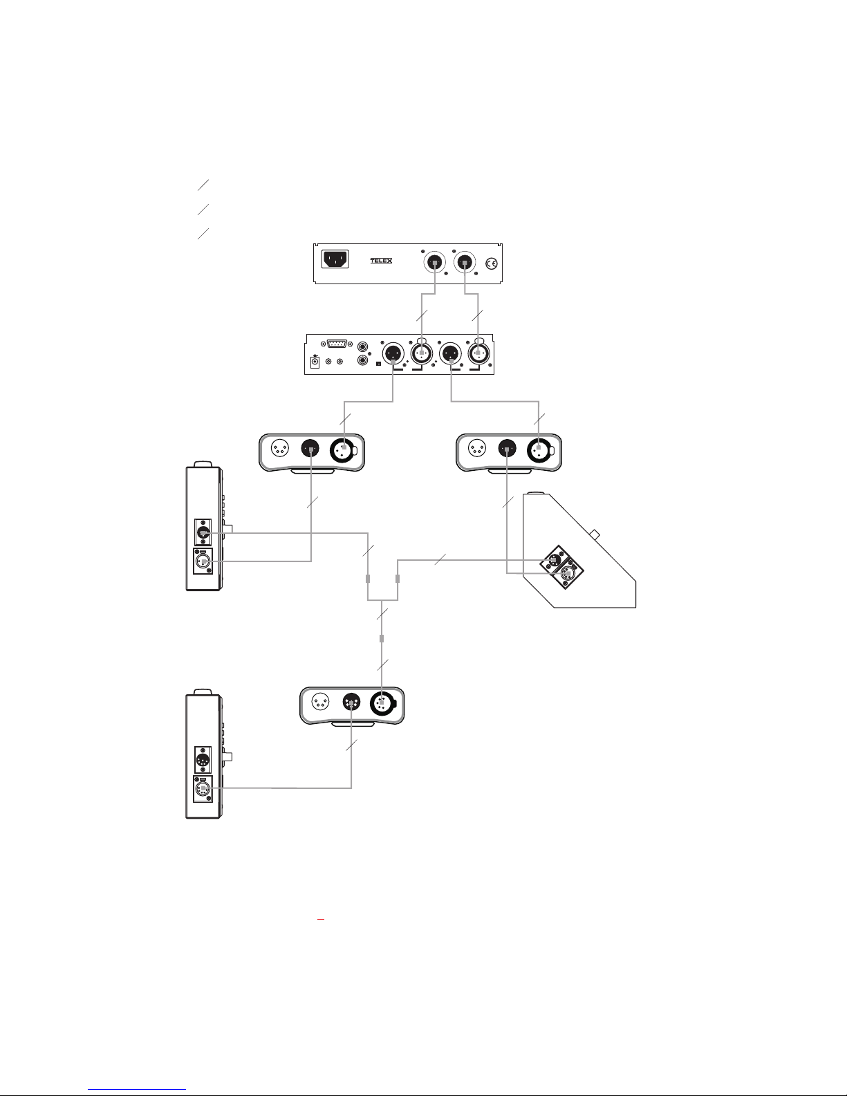
The method of connection depends on the type of box. The “S” box and “P” box versions connect to the intercom system using prefabricated cables in a phantom-powered configuration, as described below and illustrated in Figure 4. The “U”
box version is designed for permanent installation, and it can be either phantom powered or locally powered. Examples are shown in Figures 6 and 7.
Description of Phantom Powered Connection
In this method, operating power and intercom audio for the entire intercom system
are carried over the same wires. The advantage of this method is simplicity of connection. Also, the system power supply (PS2000L, SPS2000A etc.) automatically
provides what is known as a terminating impedance for the intercom system. Without
this terminating impedance, the sound quality will be very distorted, and the levels
will shift every time additional stations are connected. The disadvantage of the phantom power method is that some operating power is lost over very long intercom cables, and performance at distant intercom stations may be reduced. Generally, if
intercom stations are within a few hundred feet from the system power supply, phantom power will be sufficient. Also note that increasing the number of stations will reduce the overall operating distance. Phantom power is generally the only method that
will be used to connect the “S” and “P” box versions, since these versions are usually
connected with relatively short cables of less than 200 ft. Figure 4
trates a phantom powered intercom system with "S" and "P" type stations. Figure 6,
page 15, illustrates phantom power for "U" boxes.
Note that the distance over which power can be delivered is less than the distance
over which audio can be delivered. Audio can be delivered for several miles to locally powered stations as described below.
Description of Locally Powered Connection
Only the "U" box has provisions for local power. The 3-pin connectors on the
☞
"S" box and "P" box do not permit this type of connection.
, page 13, illus-
11
Page 12

Audiocom®
Using this method, an intercom station is connected to the intercom line just like any
phantom-powered intercom station, except that a local power supply is also connected. This local power supply is located with the intercom station and provides
power for that station only. Since power loss on the intercom lines is no longer an issue, the operating range is now limited only by the audio transmission range, which
is several miles. Another advantage to this method is that more stations can be connected to the intercom channels. When local power is supplied to an intercom station, the station detects this and automatically disconnects from the system's
phantom power supply.
Figure 6
ered "U" boxes. As long as a system power supply (PS2000L, SPS2000A, etc.) is located somewhere in the intercom system, the proper terminating impedance will still be
supplied for all stations. However ,if all stations are locally powered, and there is no
system power supply ,a special line termination must be installed as described below.
All Locally Powered Intercom Stations (Dry Lines)
If intercom stations are widely distributed, you can dispense with a system power
supply (PS2000L, SPS2000A, etc.) and use local power for each station. When no
power is delivered on the intercom channels, this is known as dry-line operation.
Since a system power supply is not used, a line termination must be inserted in each
intercom channel for proper operation. Again, note that only the "U" box has provisions for local power. The 3-pin connectors on the "S" box and "P" box do not permit
this type of connection. Figure 7 illustrates an intercom system using all locally powered "U" boxes.
illustrates an intercom system with both phantom powered and locally pow-
12
Page 13
1 1-channel cable
2 2-channel cable
Y “Y” cable
PS2000L (or SPS2000A etc.)
Combine / Isolate Switch
set to Isolate
To all stations
on channel 1
BP-1000
SS1000
"S" Box
100-249VAC 60/50 HZ
US2000A
PROGRAM
INPUTS
SPEAKERS
LINE LEVEL
+
-
1VRMS
EXP
P.A.
OUT
12-15VDC
1 1
®
CHN1
1
1
2
BAL - OUT
UNBAL - IN
PUSH PUSH
VOL
VOL
PGM 2
PGM 1
CHN 1
BP-1000
1
1
Y
1
Note: A JB-2 Junction
Box may be used
instead of the “Y” cable.
CHN2
MADEIN USA
1
CHN 2
To all stations
on channel 2
HEADSET LINESHEADSET LINES
1
SS1000
"P" Box
2
2
SS2000
"S" Box
BP-2000
HEADSET LINES
Figure 4. A two-channel Audiocom intercom system powered by a PS2000L Power
Supply. The power supply is set to isolate mode. In this mode, each channel is a
separate party line, and current per channel is limited to 1 amp. Note that both
single- and two-channel intercom stations may be connected by using “Y” cables
(or JB2 Junction boxes). Prefabricated cables may be used, or cables may be
constructed using Figure 5
.
13
Page 14
Audiocom®
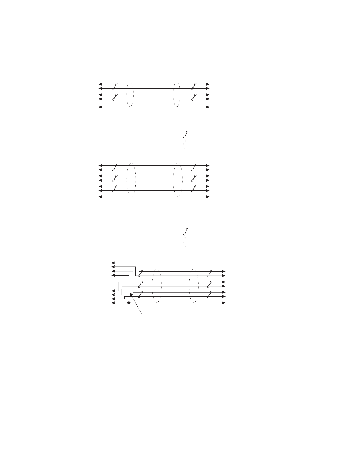
TYPICAL 1-CHANNEL CABLEWIRING
33
22
1
Shield Shield
CableType:22AWG Stranded, 2-PairTwisted-wire, with Shield
Connector Type: 3-Pin XLR Audio (Neutrik or Switchcraft)
Pin 1: Common
Channel Audio / Power
Pin 2:
Pin 3: Channel Audio / Power
: Earth ground
Shield
44
33
66
55
1
Shield Shield
CableType:22AWG Stranded, 3-PairTwisted-wire, with Shield
Connector Type: 6-Pin XLR Audio (Neutrik only, not compatible with 6-pin Switchcraft)
Pin 1: Channel 1 & 2 Common
Pin 2: No connection
Pin 3: Channel 1 Audio / Power
Pin 4: Channel 1 Audio / Power
Pin 5: Channel 2 Audio / Power
Pin 6: Channel 2 Audio / Power
Shield
: Earth ground
3
2
Ch1
1
Case
3
2
Ch2
1
Shield
Pair 1
Pair 2
1 (Both wires)
*
Denotes twisted pair.
Denotes shield.
TYPICAL 2-CHANNEL CABLEWIRING
Pair 1
Pair 2
Pair 3
Denotes twisted pair.
Denotes shield.
“Y”CABLEWIRING
Pair 1
Pair 2
Pair 3
1 (Both wires)
4
3
6
5
1 (Both wires)
Shield
*
*
Standard cables are generally constructed using a male connector at one end and a
female connector at the other end.This allows several cables to be interconnected to
create longer cable runs.
also typically provide both a male and female Neutrik connector for each intercom
channel.This permits loop-through connection of several intercom stations using the
standard cables.
each channel. Audiocom wallplates use male Neutrik connectors.
Figure 5. Audiocom cable wiring diagrams.
14
Use second drain wire if available, or add an extra section of wire.
Audiocom master stations, speaker stations and belt packs
Audiocom power supplies use a 3-pin male Neutrik connector for
Page 15
500 METERS
Headset
Listen
Panel Mic
Call
Talk
Volume
Headset
TM
SS2000
Panel Mic
SS1000
“U” Box
SS2000
SS2000
“U” Box
Headset
Listen
Panel Mic
Call
GRN 1
Ch Select
Talk
RED 2
Volume
Headset
TM
Panel Mic
Headset
Listen
Panel Mic
Call
GRN 1
Ch Select
Talk
RED 2
Volume
Headset
TM
SS2000
Panel Mic
SS2000
“U” Box
LOCAL POWER
12 to 15 VDC, 250 mA
SS2000
SS2000
“U” Box
Headset
Listen
Panel Mic
Call
GRN 1
Ch Select
Talk
RED 2
Volume
Headset
TM
Panel Mic
SS2000
SS1000
“U” Box
Headset
Listen
Panel Mic
Call
Talk
Volume
Headset
TM
Panel Mic
TM
SS2000
SS2000
“U” Box
Headset
Listen
Panel Mic
Call
GRN 1
Ch Select
Talk
RED 2
Volume
Headset
Panel Mic
PS2000L (or SPS2000A etc.)
R
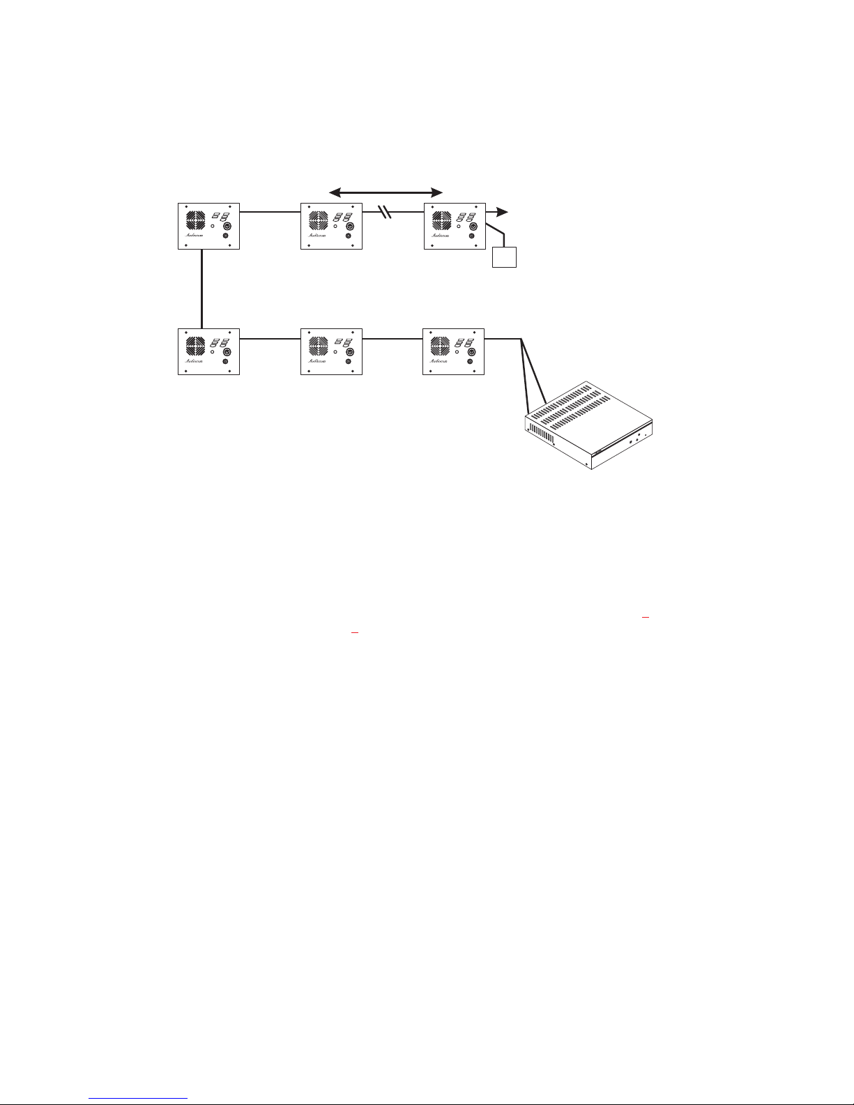
Figure 6. A two-channel Audiocom intercom system using a PS2000L Power Supply
with “U” boxes. The PS2000L is set to isolate mode. In isolate mode, each intercom
channel is a separate party line, and total current for each channel is limited to 1
amp. Note that both SS1000 and SS2000 stations may be connected, depending on
each locations’ need to communicate with one or two channels. SS1000 stations may
be connected to either channel one or two. Also note that locally powered stations
may be connected. This is recommended when stations are installed at remote
locations. Since the PS2000L provides termination for the intercom channels, no
user-installed termination is required. For SS1000 connection details refer to Figure 8
for the SS2000, refer to Figure 9
PS2000L
1
RESET
2
;
15
Page 16
Audiocom®
SS2000
SS2000
SS2000
"U" Box
Headset
Panel Mic
GRN 1
Ch Select
RED 2
Volume
TM
SS2000
"U" Box
Headset
Panel Mic
GRN 1
Ch Select
RED 2
Volume
TM
Listen
Call
Talk
Headset
Panel Mic
LOCAL POWER
12 to 15 VDC, 250 mA
Listen
Call
Talk
Headset
Panel Mic
LOCAL POWER
12 to 15 VDC, 250 mA
SS2000
SS2000
"U" Box
SS2000
SS2000
"U" Box
Headset
Listen
Panel Mic
Call
GRN 1
Ch Select
Talk
RED 2
Volume
Headset
TM
Panel Mic
LOCAL POWER
12 to 15 VDC, 250 mA
Headset
Listen
Panel Mic
Call
GRN 1
Ch Select
Talk
RED 2
Volume
Headset
TM
Panel Mic
LOCAL POWER
12 to 15 VDC, 250 mA
SS2000
SS2000
"U" Box
SS2000
SS2000
"U" Box
Headset
Listen
Panel Mic
Call
GRN 1
Ch Select
Talk
RED 2
Volume
Headset
TM
Panel Mic
LOCAL POWER
12 to 15 VDC, 250 mA
Headset
Listen
Panel Mic
Call
GRN 1
Ch Select
Talk
RED 2
Volume
Headset
TM
Panel Mic
LOCAL POWER
12 to 15 VDC, 250 mA
LINE
TERMINATION
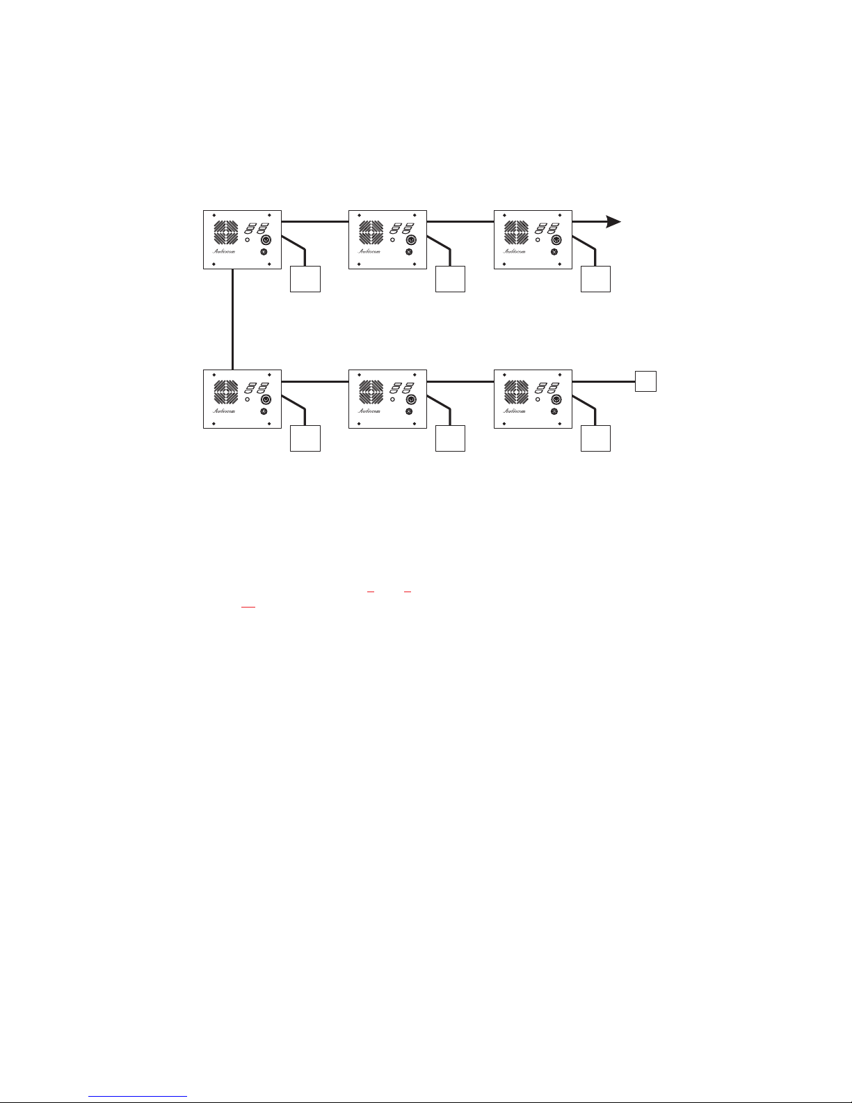
Figure 7. An example of an Audiocom intercom system using all locally powered “U”
box stations, with no power being distributed on the intercom channels (dry lines).
Since an Audiocom power supply is not used, the installer must connect a line
termination somewhere in each channel for proper operation. For intercom channel
connections, refer to Figures 8
Figure 10
.
and 9. The required line termination is shown in
16
Page 17
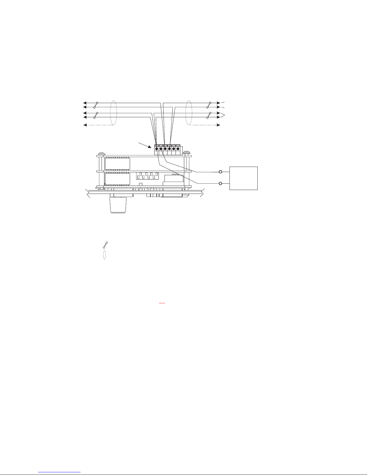
TO ADDITIONAL
SINGLE-CHANNEL STATIONS
TO POWER
SUPPLY CONNECTOR
Pair 1
Pair 2
Channel Audio high / Power
Channel Audio low / Power
DC Common
Shield*
PIN 1
CableType:22AWG Stranded, 2-PairTwisted-wire, with Shield
Denotes twisted pair.
Denotes shield.
*Shield: Earth ground (Connect at power supply only. Do not short to DC common)
Shield*
OPTIONAL LOCAL
POWER SOURCE
12 to 15 VDC, 250 mA
+ DC
COMMON
Figure 8. Audiocom mode connections for a SS1000 Intercom Station in a “U” box.
Note: For Clear-Com connection, use the Unbalanced Mode Intercom Channel
pin-out information listed on page 25
.
17
Page 18
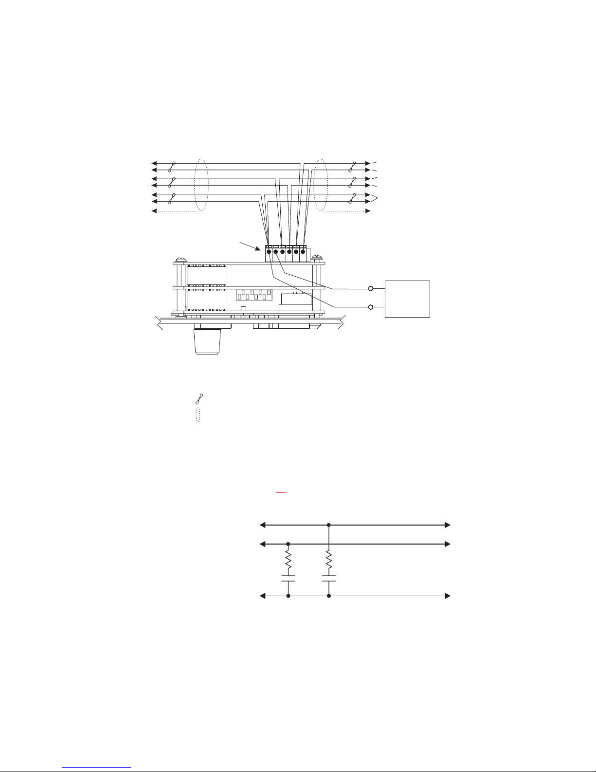
Audiocom®
SINGLE- OR TWO-CHANNEL STATIONS
TO ADDITIONAL
Shield*
PIN 1
Cable Type: 22AWG Stranded, 3-Pair Twisted-wire, with Shield
Denotes twisted pair.
Denotes shield.
TO POWER
SUPPLY CONNECTOR
Pair
Pair
Pair
Shield*
Channel 2 Audio low / Power
Channel 2 Audio high / Power
Channel 1 Audio low / Power
Channel 1 Audio high / Power
DC Common
OPTIONAL LOCAL
POWER SOURCE
12 to 15 VDC, 250 mA
Use PN: 59702-000
+ DC
COMMON
*Shield: Earth ground (Connect at power supply only. Do not short to DC common)
Figure 9. Audiocom mode connections for a SS2000 Intercom Station in a “U” box.
Note: For Clear-Com connection, use the Unbalanced Mode Intercom Channel
pin-out information listed on page 25
.
Channel audio low
Channel audio high
Resistors 150 Ohm, 1/4W
Capacitors 22 f, 35V
µ
Non-polarized Electrolytic
Common
Figure 10. Audiocom mode line termination for dry-line operation. (One required for
each channel.) The termination is available via PN: 9020-7550-000.
18
Page 19

Headset / Headphone / Microphone Connections
The Headset and Panel Mic connectors may be used in a variety of talk/listen configurations:
To use a dynamic-mic headset or dynamic, telephone-style handset for talk and
●
listen, connect it to the Headset connector.
To use headphones for listening and a panel microphone for talkback, connect
●
the headphones to the Headset connector and connect the microphone to the
Panel Mic connector.
To use a handheld dynamic microphone for talkback and the internal speaker for
●
listening, connect the microphone to the Headset connector.
To use a panel microphone for talkback and the internal speaker for listening,
●
connect the microphone to the Panel Mic connector.
For Headset and Panel Mic connector specifications, see page 24. For best re-
☞
sults in noisy environments, a noise canceling (directional or cardioid) microphone is highly recommended.
If you are connecting a headset, telephone handset, or handheld dynamic micro-
☞
phone, make sure that DIP switch 4 is properly set for either balanced or unbalanced microphone. See "Dynamic Microphone Type Selection", page 9
To connect a Telex model EGM-12N or EGM-18N panel microphone, line up
☞
the arrow on the top of the microphone with the top of the connector on the intercom station.
.
19
Page 20

Audiocom®
Power-Up
Make sure any local power supplies are plugged in, then turn on the power switches
of any phantom power supplies (PS2000L, SPS2000A etc.).
If you are using a large number of locally powered intercom stations, you should
☞
activate their local power supplies before activating any phantom power supply.
Otherwise, you may get an overload indication on the phantom supply. In this
case, either reset the phantom supply, or momentarily turn it off, then on.
Sidetone Adjustment
The SS1000 and SS2000 use full-duplex audio (the same as con v entionaltelephone
lines) in which the talk and listen audio are sent and received on the same wires. Thus,
when you talk, you also here your own voice back as with a telephone. If you are using
the built-in speaker for listening and a panel microphone or handheld microphone for
talkback, you could experience unwanted feedback, since the microphone may pick up
your returned voice audio from the speaker and re-amplify it. This could also happen if
you are using a headset or headphones with open-ear style earmuffs. On the other hand,
if you are using earmuffs that completely enclose the ears, the microphone is not likely
to pick up the returned audio. And, a certain amount of your own voice level is desirable to overcome the muffled sensation when talking. The sidetone adjustment is different for these different operating conditions:
If you are using the speaker with a panel microphone, or if you are using an
open-ear style headset or headphones, adjust sidetone as follows:
1. SS2000 only: activate channel 1 as described in the operating instructions, page
.
22
2. Activate talk and listen as described in the operating instructions.
3. Slowly increase the volume to maximum while talking into the microphone.
4. Using a small flat-bladed screwdriver, adjust the channel 1 sidetone trimmer (Fig-
, page 6, item 12) to minimize your voice level in the headphones.
ure 2
20
Page 21

5. SS2000 only: activate channel 2 and repeat the above steps to adjust the channel
2 sidetone.
6. Install the intercom station mounting screws after completing the adjustments.
The station is now ready for use.
If you are using headphones that completely enclose the ears, adjust sidetone as
follows:
1. SS2000 only: activate channel 1 as described in the operating instructions on
page 22.
2. Activate talk and listen as described in the operating instructions.
3. Set the volume control to the normal listening level for intercom audio.
4. While talking into the microphone, use a small flat-bladed screwdriver to adjust
the channel 1 sidetone trimmer (Figure 1
the headphones at an acceptable level.
5. SS2000 only: activate channel 2 and repeat the above steps to adjust the channel
2 sidetone.
6. If the intercom station will be mounted in place, mount the case back as described below before reinstalling the faceplate. If the “S” box or “P” box version
will be used in a portable configuration, you may reinstall the faceplate in the
case and proceed to the operating instructions.
) so that you can hear your own voice in
21
Page 22

Audiocom®
Operation
Channel Select (SS2000 Only)
Tap the Ch Select key to select channel 1 or 2. The key is green when channel 1 is selected and red when channel two is selected.
Headset / Headphone / Speaker / Microphone Selection
To use a headset or telephone style handset, set the Speaker and Panel Mic keys
●
to off.
To use headphones with a panel microphone, set the Speaker key to off and set
●
the Panel Mic key to on.
To use the speaker with a handheld dynamic microphone, set the Speaker key to
●
on and set the Panel Mic key to off.
To use the speaker with a panel microphone, set the Speaker and Panel Mic keys
●
to on.
Receiving Calls
1. When there is an incoming call signal the Call ke ywill flash red. There will also be a
beep tone in the headphones or speaker if the beep feature is activated(page 9).
SS2000 only: incoming call indication is provided only for the currently selected
☞
intercom channel.
2. Turn on the Talk and Listen keys and begin your conversation. Turn the keys off
when finished.
You can turn the talk and listen keys on in either momentary or latched mode.
☞
For momentary operation, press and hold the key. For latched operation, tap the
key to turn it on. Then tap it again to turn it off when finished.
Calling an Intercom Channel
1. SS2000 only: select the desired intercom channel.
22
Page 23

2. Press and hold the Call key. An inaudible call signal will be sent, and the Listen
key will automatically turn on.
3. When you hear a response, release the Call key and activate the talk key.
4. Turn off your Talk and Listen keys to end the conversation.
23
Page 24

Audiocom®
Specifications
General
Power Requirements:
Phantom Power:24 VDC nominal (12 to 30 VDC), 175 mA
Local Power:12 to 15 VDC, 250 mA
Dimensions: See Figure 3
Environmental Requirements:
Storage: -20°C to 80°C; 0% to 95% humidity, non-condensing
Operating: -15°C to 60°C; 0% to 95% humidity, non-condensing
Dynamic-mic Headset
Microphone: 50 to 200 ohm, dynamic (balanced or unbalanced)
Headphones: 150 to 600 ohm, monaural
Connector Type: XLR-4M
Pin 1 Microphone low
Pin 2 Microphone high
Pin 3 Headphone high
Pin 4 Headphone low
Panel Microphone
Microphone: 5 kohm, electret (-57 dB)
Connector Type: NTRK-8F
Pin 1 Common
Pin 2 Microphone high
Pin 3 +12 VDC microphone bias
Intercom Channels, Balanced Mode (SW1 set to BAL position)
Output Level:1 Vrms nominal
Input Impedance: 300 ohms
Bridging Impedance: greater than 10,000 ohms
Sidetone: -40 dB, 35 dB adjustable range
Call Signaling:
Send: 20 kHz ±100 Hz, 0.5 Vrms ±10%
Receive:20 kHz ±800 Hz, 100 mVrms
Mic-Kill Detect Frequency:24 kHz ±800 Hz, 100 mVrms
Noise Contribution: less than -70 dB
Common Mode Rejection Ratio: greater than 50 dB
Connector Type: Six-position terminal block with screw-in wire clamps
Pin 1 Audio and DC Common
Pin 2 Local power (12 to 15 VDC, 65 to 150 mA)
Pin 3 Intercom channel 1 audio low and +24 VDC phantom power
Pin 4 Intercom channel 1 audio high and +24 VDC phantom power
Pin 5 Intercom channel 2 audio low and +24 VDC phantom power
Pin 6 Intercom channel 2 audio high and +24 VDC phantom power
24
Page 25

Intercom Channel, Unbalanced Mode (SW1 set to Unbalanced or UNBAL position)
Output Level:1 Vrms ±10%
Input Impedance: 150 ohms
Bridging Impedance: greater than 10,000 ohms
Call Signaling:
Send: 11 ±3 VDC
Receive:4 VDC minimum
Connector Type: Six-position terminal block with screw-in wire clamps
Pin 1 Common
Pin 2 Local power (12 to 15 VDC, 65 to 150 mA)
Pin 3 Channel 1 +24 VDC input
Pin 4 Channel 1 Intercom audio high and DC call
Pin 5 Channel 2 +24 VDC input
Pin 6 Channel 2 Intercom audio high and DC call
25
Page 26

Audiocom®
Factory Service and Parts Information
When returning equipment for repair include your return address, telephone number
and proof of date of purchase, along with a description of the problem.*
The address for Audiocom equipment returns and parts information is:
Service Department
Telex Communications, Inc.
West 1st Street
Blue Earth, Minnesota 56013 U.S.A.
Telephone: (507) 526-3205
(Collect calls not accepted)
Warranty Repairs - If in warranty, no charge will be made for the repairs. Equipment
returned for warranty repair must be sent prepaid and will be returned prepaid.
Non-Warranty Repairs - Equipment that is not under warranty must be sent prepaid
to Telex. If requested, an estimate of repair costs will be issued prior to service. After
your approval and completion of the repairs, the equipment will be returned on a collect basis. Collect charges may be avoided by sending a signed check for payment in
full along with your signed estimate approval form (shipping charges are included in
the estimate).
* For sales / technical support and system design contact:
Pro Audio Sales Department
Telex Communications, Inc.
12000 Portland Avenue South
Burnsville, Minnesota 55337 U.S.A.
Telephone: (952) 884-4051
(Collect calls not accepted)
26
Page 27
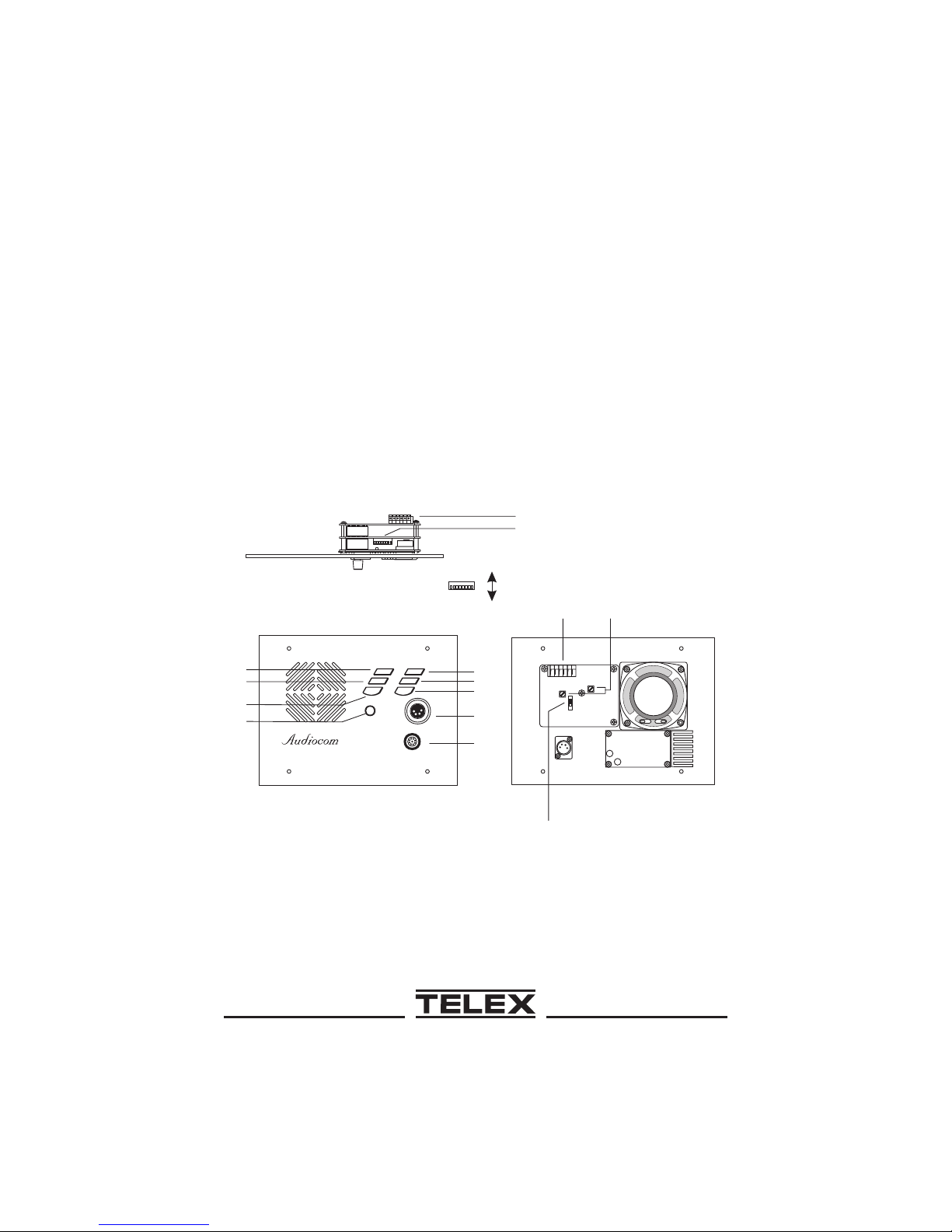
Addendum
Document Affected: SS1000/SS2000 User Instructions, Publication Number
9350-7620-000 Rev. D
Addendum Number: 1
General Instructions: Use this addendum with Revision D of the user instruc-
tions. This information will be included in Revision E.
When setting the DIP switches, it is difficult to identify the open and closed positions. The open and closed positions are shown below.
TOP VIEW OF
FACEPLATE
3
4
5
6
S S2000
1
2
DIP SWITCH POSITIONS
CLOSED (ON)
OPEN (OFF)
Listen
Panel Mic
Speaker
Volume
ChS el ect
Call
Talk
Panel Mic
Heads et
GRN 1
RED2
TM
10
11
7
8
9
Ch 1
1
SW1
12
Ch 2
BACK SIDE OF
13
FACEPLATE
®
Page 28

TELEXCOMMUNICATIONS,INC.12000 Portland Ave.So.,Burnsville,MN55337 U.S.A.
9350-7620-000Rev.F,1/01
®
 Loading...