

Page 1

Q II - FOH
Operators Manual
Klark Teknik Building
Walter Nash Road
Kidderminster
Worcestershire
DY11 7HJ
Tel: +44 (0) 1562 741515
Fax: +44 (0) 1562 745371
Email: info@uk.telex.com
Website: www.ddaconsoles.com
Q II - FOH Operators Manual
Telex Communications (UK) Limited
In line with the company’s policy of continual improvement, specifications and function maybe subject
to change without notice. This Operator Manual was correct at the time of writing. E&OE.
Page 2

Contents
3 DECLARATION OF CONFORMITY
4 GENERAL INFORMATION
5 THE Q2 IN USE
7 WARRANTY
9 DIMENSIONS
10 SPECIFICATIONS
12 WIRING CONSIDERATIONS
12 GROUNDING
15 ATTENTION
16 MODULE DESCRIPTIONS
18 THE MATRIX SECTION
19 THE 20DB PAD
20 INPUT MODULE
28 VCA INPUT MODULE
31 STEREO EFFECT RETURN MODULE
36 MONO SUBGROUP OUTPUT MODULE
40 STEREO SUBGROUP OUTPUT MODULE
44 LCR SUBGROUP OUTPUT MODULE
48 FOLDBACK MASTER MODULE
49 AUXILIARY MASTER MODULE
50 STEREO MASTER MODULE
56 MASTER CONNECTOR PANEL
57 VCA MASTER MODULE
62 THE AUDIO MASTER MODULE
62 Q2 TECHNICAL DESCRIPTION
66 THE AUXILIARY MASTER MODULE
67 THE FOLDBACK MASTER MODULE
68 THE INPUT MODULE
76 THE MONO GROUP OUTPUT MODULE
78 THE STEREO GROUP OUTPUT MODULE
79 THE LCR GROUP OUTPUT MODULE
80 Q2 VCA
83 VCA MASTER MODULES
Q2 OPERA TION AND MAINTENANCE MANUAL 9601 2
Page 3

Declaration of Conformity
The Manufacturer of the Products covered by this Declaration is
Klark Teknik Building, Walter Nash Road, Kidderminster, Worcestershire, DY11 7HJ.
The Directives Covered by this Declaration.
89/336/EEC Electromagnetic Compatibility Directive, amended by 92/31/EEC & 93/68/EEC
73/23/EEC Low Voltage Equipment Directive, amended by 93/68/EEC.
The Products Covered by this Declaration.
Equipment type Product Name Variants
Audio Mixing Console Q2 Q2 VCA
Audio Mixing Console Q2 Monitor Meterbridge
Audio Mixing Console QMR Meterbridge
Audio Mixing Console FMR
Audio Mixing Console Forum PA,Matrix,Mute
Audio Mixing Console Forum Monitor Meterbridge
Audio Mixing Console XL200
Audio Mixing Console XL250
The Basis on which Conformity is being Declared
The products identified above comply with the protection requirements of the EMC Directive and with the principal elements of
the safety objectives of the Low Voltage Directive, and the manufacturer has applied the following standards:
EN 55013 : 1990
Limits and methods of measurement of radio disturbance characteristics of Broadcast Receivers and Associated Equipment.
EN 50082-1 : 1992
Electromagnetic Compatibility - Generic Immunity Standard Part 1. Residential, commercial and light industry.
EN 60065 : 1994
Safety requirements for mains operated electronic related apparatus for household and similar general use.
The technical documentation required to demonstrate that the products meet the requirements of the Low Voltage Directive has
been compiled by the signatory below and is available for inspection by the relevant enforcement authorities. The CE mark was
first applied in 1996.
Signed: ................................ G.M.Squires
Authority: Product Support Manager.
Date: 1st, January 1997.
Attention
The attention of the specifier, purchaser, installer, or user is drawn to special measures and limitations to use which must be
observed when these products are taken into service to maintain compliance with the above directive. Details of these special
measures and limitations to use are available on request, and are also contained in product manuals.
Q2 OPERA TION AND MAINTENANCE MANUAL 9601 3
Page 4

GENERAL
INFORMATION
Three channel or Left, Centre, Right panning differs from the
normal stereo panning arrangement in that where the conventional
left/right pan moves the signal across the stereo image, LCR
panning moves the mono signal across three distinct positions.
Using LCR panning gives a more spatial effect, offers more control
over vocal and effects positioning, and brings theatre performances
to life in a way that conventional stereo panning cannot.
In the LCR mode, the pan pot acts as follows. When panned hard
left, the signal is only fed to the left channel of the main output (or
sub-group). As the pan is rotated towards the centre, the signal to
the left decreases, and the signal to the centre channel increases
until at dead centre the signal only goes to the centre output. At
this point, no signal is fed to the right channel at all.
LEFT CENTRE RIGHT
Rotating the pan pot further (to the right) decreases the centre feed
while the right feed increases until at full clockwise rotation the
signal is only on the right channel.
Q2 OPERA TION AND MAINTENANCE MANUAL 9601 4
Page 5

THE Q2 IN USE
Providing a hard centre image in addition to left and right speaker
clusters improves localisation, as has already been proven in the
cinema industry. Stars and soloists are typically mixed to the centre
channel. Back-up vocals and orchestra or band may be wrapped
around the vocalist in stereo, or panned across the three channels.
In Theatrical performances, LCR panning may be used to follow an
actor around the stage.
Q2's typical use in the theatre maybe as follows.
The main LCR output is used to feed the audience clusters. Further
flexibilty in mixing is provided if the 4 LCR sub-groups are fitted,
as groups can be formed with all signals in place, then simply
fader-controlled as a group to the main output.
Four of the auxiliary sends, labelled foldback, may be used to
provide stage monitoring, as the term foldback suggests. The other
four auxiliaries are then free for effects sends, perhaps using the
dual concentric controls as stereo pairs.
The matrix section has numerous uses. Apart from creating foyer
and backstage feeds, it can be used for distributed loudspeaker
arrays for SPL control further back in the house (see the section on
the Q2 matrix). If the Q2 stereo sub-groups are fitted, the matrix is
fully stereo, so that delayed arrays can be easily set up as distinct
and controllable stereo pairs down each side of the auditorium.
Q2 OPERA TION AND MAINTENANCE MANUAL 9601 5
Page 6
Consultants and contractors will be pleased to note that Q2 has
balanced inputs and outputs throughout, including inserts. In
addition, all inputs and outputs (with the obvious exception of the
mic input) operate at a nominal level of +4dBu. This alone means
no catering for special levels on inserts, no compensating for
unbalanced insert sends which combine with balanced returns.
System connection and signal flow is therefore not console
dependant.
LEFT CENTRE RIGHT
F/B
(4)
EFFECTS
Q2
MATRIX OUTPUTS (8)
Q2 OPERA TION AND MAINTENANCE MANUAL 9601 6
Page 7

WARRANTY
If within a period of twelve months from the date of delivery of the
equipment to the End User it shall prove defective by reason only
of faulty materials and/or workmanship (but no faulty design) to
such an extent that the effectiveness and/or the usability thereof is
materially affected, the Equipment or the faulty component shall be
returned to the Distributor or DDA and subject to the following
conditions the Distributor or DDA will repair or at its option replace the defective components. Any components replaced will
become the property of DDA.
Any Equipment or component returned will be at the risk of
the End User whilst in transit (both to and from the Distributor or
DDA) and postage and/or freight charges must be prepaid.
This Warranty shall only be available if:-
i) The Equipment has been properly installed in accordance
with the instructions contained in this manual.
ii) The End User has notified the Distributor or DDA in writing
within 14 days of the defect appearing.
iii) No persons other than authorised representatives of DDA or
the Distributor have effected any replacement of parts,
maintenance adjustments or repairs to the Equipment.
iv) The End User has used the Equipment for such purposes as
DDA recommends with only such operating supplies as meet
DDA’s specifications or approval and otherwise in all
respects in accordance with DDA’s recommendations.
Defects arising as a result of the following are not covered by this
Warranty : -
Faulty or negligent handling, chemical or electro-chemical or
electrical influences, accidental damage, Acts of God, neglect,
defficiency in electrical power , air conditioning or humidity
control.
Benefit of this Warranty may not be assigned by the End User.
End Users who are consumers should note that their rights
under this Warranty are in addition to and do not affect any other
rights to which they may be entitled against the seller of the
Equipment.
Q2 OPERA TION AND MAINTENANCE MANUAL 9601 7
Page 8

DDA shall not be liable for any damage caused to persons
or property due to :-
i) Incorrect usage of the Equipment
ii) Other equipment attached to the Equipment, which is not
approved by DDA
iii) Modifications made by non-authorised persons, or by using
non-recommended parts, or incorrectly made.
In no circumstances shall DDA be liable for any indirect or
consequential costs, damages or losses (including loss of business
profits, operating time or otherwise) arising out of the use or
inability to use the product, whether or not the likelihood of
damage was advised to DDA or its distributor.
Fuses and filament lamps are specifically excluded from the
warranty
This notice does not affect your statutory rights.
Q2 OPERA TION AND MAINTENANCE MANUAL 9601 8
Page 9

DIMENSIONS
Q2 Dimensions
24 Input Frame
Width : 1255mm / 49.4"
Depth : 810mm / 31.9"
Height : 368mm / 14.5"
32 Input Frame
Width : 1505mm / 59.25"
Depth : 810mm / 31.9"
Height : 368mm / 14.5"
40 Input Frame
Width : 1755mm / 69.1"
Depth : 810mm / 31.9"
Height : 368mm / 14.5"
48 Input Frame
Width : 2005mm / 78.9"
Depth : 810mm / 31.9"
Height : 368mm / 14.5"
Floorstand (optional)
Height to underneath of console : 700mm / 27.5"
Q2 Power Supply Dimensions
Height : 134mm / 5.25" (3U rack mounting)
Depth : 265mm / 10.5"
Width : Front panel 483mm / 19"
Housing 438mm / 17.25"
Nett Weight (unpacked): 7.8 Kg / 17.2 lbs
Q2 OPERA TION AND MAINTENANCE MANUAL 9601 9
Page 10

SPECIFICATIONS
Note : All specifications relate to dBu, ie 0dBu = 0.775V RMS
MAXIMUM GAIN
Mic Input to Mix Output: 86dB
Line Input to Mix Output: 40dB
FREQUENCY RESPONSE
Mic Input to Mix Output: 20Hz , -0.50dB
(gain 55dB) 20kHz, -0.20dB
Line Input to Mix Output 20Hz , -0.50dB
(gain 0dB) 20kHz, -0.20dB
NOISE, DIN Audio Weighted
Microphone Input
Gain 55dB, EIN Ref 200 Ohm <-127.5dBu
Line Input to Mix Output
Gain 0dB, 16 inputs routed <-83dBu
DISTORTION
Microphone Input to Mix Output
-50dBu input, +4dBu output <0.005%
Line Input to Mix Output
+4dBu input, +4dBu output <0.005%
CROSSTALK
Adjacent Channel, 1kHz <-100dBu
Group to Mix, 1kHz <-88dBu
Fader Attenuation 1kHz <-95dBu
Panpot Isolation, 1kHz <-72dBu
Q2 OPERA TION AND MAINTENANCE MANUAL 9601 10
Page 11

Q2 Power Supply Specifications
AC Mains Voltage selection :- 110V/120V/220V/240V
Power Consumption (max) : 750VA
AC Mains frequency : 50Hz. - 60Hz
Fuse Ratings: 220/230/240V - 6.3A
90/100/120V - 10A
Cooling Method: Internal fan
DC Power Outputs: +17 Volts, 7A max
-17 Volts, 7A max
+48 Volts, 0.35A max
Q2 OPERA TION AND MAINTENANCE MANUAL 9601 11
Page 12

WIRING
CONSIDERATIONS
To take full advantage of the excellent audio performance of DDA
mixing consoles, it is essential that the installation is carried out
with care and attention. All audio signals are referenced to the
system earth, which must be clean and noise-free, and essentially
equipotential. In addition, the earth system integrity is absolutely
necessary for safety .
Do not disconnect the mains earth wire from each piece of equipment as this could create a hazardous situation.
If in doubt consult a competent engineer and your local electricity
supply company to ensure that safety regulations are not infringed
or negated.
GROUNDING
The console metalwork MUST ALWAYS be connected to the
Mains earth via the PSU lead. However, the user has a choice as
regards the Audio 0V.
The Audio 0V should be taken from the Studio earthing System
which should take the form of a star wired system. Decide on a
central point for the main earth system and starfeed to all mains
outlets and equipment racks from this point. Common electrical
wiring practice is to daisy-chain earth wires from outlet to outlet,
but this is not recommended for audio installations. The location of
the earth system star point should be in a convenient, easily
accessible position, such as the main equipment rack. The star
point must then be connected to the incoming mains earth but
preferably should be connected to a totally separate technical
earth (if local electrical regulations permit).
This should take the form of a large copper plate or stake
buried as deeply as practical into the ground (a 1 metre [39"] copper stake hammered fully into the ground would be suitable).
This should then be fed to the studio star system via heavy gauge,
low impedance cable, with adequate precautions being taken to
prevent excessive corrosion of the cable/earth stake.
Q2 OPERA TION AND MAINTENANCE MANUAL 9601 12
Page 13

Do not install other equipment (lighting, vending machines etc) to
the technical earth - only use it for Audio Equipment.
If the star point is derived from mains earth, however, and not from
a ground stake/plate, install separate clean and dirty mains outlets,
wired individually to the mains distribution box. Use the clean
supply for all audio equipment, and the dirty supply for all lighting,
vending machines etc. Do not mix the two systems. It may be
necessary to install an isolating transformer for the clean supply to
ensure adequate isolation from mains-borne interference. The
isolating transformer must be of adequate current capability and
should incorporate a Faraday Shield, connected to the incoming
mains earth.
All audio connecting cables should be good quality twin screened
cable. Do not use single screened cable.
It is very important that the screen is not used as the signal return.
Therefore connect the screen at one end only. Connecting the
screen at both ends will cause an earth loop into which external
hum fields will be induced.
In areas where high levels of radio frequency interference are
present the open end of the screen can be connected to earth
through a 0.01 microfarad capacitor. This will appear as a short
circuit at high frequencies, and lower the effective shield impedance to earth. However at audio frequencies the reactance of the
capacitor will be sufficiently high to not cause an earth loop.
In general, the screen should be connected at the signal source,
and not at the signal destination. The exception to this rule of
thumb is when connecting to an unbalanced input or to an electronically balanced input. In these cases the wires being screened
are referenced to the destination earth.
Electronically balanced outputs which are to be operated in the
unbalanced mode should be unbalanced at the output connector,
not at the signal destination so that the signal current returns to
earth via the shortest, least reactive route.
Q2 OPERA TION AND MAINTENANCE MANUAL 9601 13
Page 14

Rack mounted equipment which has unbalanced inputs and outputs
may need to be electrically isolated from the equipment rack and/
or other equipment to avoid earth loops.
DO NOT DISCONNECT THE MAINS EARTH.
Connect all equipment in a logical sequence, starting with the
monitor systems, followed by the multitrack and then the stereo
machines and the peripheral devices and isolate any earth loop
problems as they occur. It is very difficult to rectify a
problematical installation after everything has been connected due
to interaction between the various earth loops.
The Console is supplied with 1 power supply unit 3U high (5.25"),
19" rack mounting. The PSU supplies the console with +18V, 18V, +48V phantom and Audio Ground (0V). Connection
between supplies and console is a cable, terminated at both ends by
polarised Harting multiway connectors. At the console the
connector is located on the rear panel of the console.
The normal length of the PSU-Console cables is 25 feet (8
metres).
The power supply requires the following Mains supplies :-
220-240 Volts AC, 6.3 A (Maximum current ratings)
100-120 Volts AC, 10 A (Maximum current ratings)
and is connected to the AC Mains via standard IEC 3 pin lead.
The PSU has an integral low-noise cooling fan and should be
provided with at least 1U (1.75") of rack space above and below it.
WARNING - ENSURE THAT THE CORRECT VOLTAGE
HAS BEEN SELECTED ON THE PSU BEFORE SWITCHING
ON THE UNIT.
The selection of the mains input voltage is made by removing the
fuse holder from the rear panel of the PSU, and replacing it in the
correct orientation for the local voltage supply. Ensure that the
correct value fuse is fitted to correspond to the supply .
Q2 OPERA TION AND MAINTENANCE MANUAL 9601 14
Page 15

ATTENTION
CABLES
This product should only be used with high quality, screened
twisted pair audio cables, terminated with metal bodied 3-pin XLR
connectors. The cable shield should be connected to Pin 1. Any
other cable type or configuration for the audio signals may result in
degraded performance due to electromagnetic interference.
ELECTRIC FIELDS
Should this product be used in an electromagnetic field that is
amplitude modulated by an audio frequency signal (20Hz - 20Khz),
the signal to noise ratio may be degraded. Degradation of up to
60dB at a frequency corresponding to the modulation signal may be
experienced under extreme conditions (3V/m, 90% modulation).
No permanent damage or degradation of performance will be
caused by these conditions.
Q2 OPERA TION AND MAINTENANCE MANUAL 9601 15
Page 16

MODULE
DESCRIPTIONS
Before describing the module functions, it is worth looking at some
of the facilities in some depth which would otherwise be too long to
describe within the module texts.
THE CUE SYSTEM
SOLO MODE
Q2's cue system, smart cue, is as flexible as you want it to be. It
can be operated in several modes, the simplest of which is of course
a regular PFL solo system.
The three modes of cue listening are PFL (pre-fade), AFL (afterfade), and SIP (solo-in-place). The overall level of the cue signal
fed to the monitors is adjustable on the stereo master module, so
PFL signals will not present high level signals to the monitor
outputs.
The solo-in-place mode is different from the normal recording SIP
or other SIP modes in that cueinga channel or group will not
actually mute all the other channels. It would would be useless if
by soloing a group you cut the inputs to that group.
Instead, in SIP mode, any group cue pressed will override and
replace whatever signal is present on the main output, until the cue
is released when the original signal is returned. No channels are
muted, so all active parts of the group remain intact.
As this function could be considered as dangerous in a performance
situation, the SIP mode switch is located at the top of the module
away from all the other cue mode controls.
CUE PRIORITY
CUE BUTTON ACTION
MOMENTARY OR
LATCHING
Q2's smartcue system incorporates a cue priority function. Two
leds on the stereo master module indicate whether an INPUT CUE
or an OUTPUT CUE is active. If an output cue is active, pressing
an input cue will override and replace the output cue until released,
when the output cue signal will be returned. This is an important
facility in live sound production.
The action of the cue buttons is functional in two ways.
If the button is pressed quickly (normally), the channel latches into
cue mode, with a flashing led , and remains in cue mode until the
button is pressed again. This is the "latching" mode, and is the
normal method of cue operation.
Q2 OPERA TION AND MAINTENANCE MANUAL 9601 16
Page 17

If the cue button is held depressed for at least one second, the cue
will become momentary , and only active until the cue button is then
released. This allows you to listen to a signal for a short period of
time and only have to press the button once.
CUE INTERLOCK
MODE
MASTER CUE RESET
A further method of operation involves a choice of additive or
exclusive cues.
In normal mode, the cues are additive. That is, any cue button
pressed adds its signal to any cues already pressed, so any number
of cues may be active at one time. To clear all the cues completely,
press the CUE RESET button on the stereo master module.
In the INTERLOCKED mode. pressing a cue button will clear the
previous cue, so only one cue may ever be active at any time. This
prevents cue signals adding.
Q2 OPERA TION AND MAINTENANCE MANUAL 9601 17
Page 18

THE MATRIX
SECTION
Nowadays, any console destined for theatre or similar live
performance use must have a matrix. This matrix takes the group
signals, and probably other signals, and allows different sub mixes
to be created for many uses.
Traditionally, matrices have been used to provide backstage mixes,
dressing room and foyer feeds where some elements of the mix are
not required. For example, you may want to send a different mix of
an opera or stage show to the dressing rooms to acentuate certain
points in the peformance.
Now, with demands for sound level control increasing, a matrix is
mandatory for distributing sound throughout an auditorium. Using
the normal front of house stacks, people at the rear of a hall may
need the system power increased for suitable listening levels, while
those at the front will no doubt then be deafened. The answer is to
provide arrays of loudspeakers, with mixes of suitably delayed
signals, stretching from the front of the hall to the back, to provide
more comfortable localised levels for better audience reception.
Here, the matrix increases the potential of creativity of the
performance, as by utilising the mixing facilities of the matrix, a
more surround sound effect may be created by perhaps focusing
vocals to the front, and mixing effects and music around the hall.
Q2's matrix offers all the flexibility that you need. In addition to a
feed from all the group outputs each matrix output may be fed from
the main stereo and mono (or LCR) buses, and any 2 of the four
foldnack mixes. This latter facility is extremely useful when you
consider that you can now set up one mix on a foldback bus, and
feed portions of that mix to any or all of the matrix outputs.
With fader control, CUE and ON/OFF facilities, Q2's matrix is
peraps one of the most powerful systems available on a console.
Q2 OPERA TION AND MAINTENANCE MANUAL 9601 18
Page 19

THE 20DB PAD
One trend in modern console design that DDA has chosen not to
follow is the removal of the traditional 20dB pad in favour of a
wide range gain control system.
The reason for this is mostly due to the use of microphone input
transformers. Their position in the circuit is always before the
input amplifier. Without a pad, the risk of saturating the
transformer with high level microphone outputs is extreme, unless
very large transformers are used.
DDA's philosophy places the 20dB pad before the transformer to
eliminate the risk of transformer saturation.
Q2 OPERA TION AND MAINTENANCE MANUAL 9601 19
Page 20
INPUT MODULE
The input module is essentially the same for all subgroup versions
of Q2, with links selecting whether the buses feed 8 mono, 8 stereo,
4 LCR or 16 mono subgroups. Dedicated LCR input modules have
4 routing buttons marked A, B, C, and D instead of buttons 1-8.
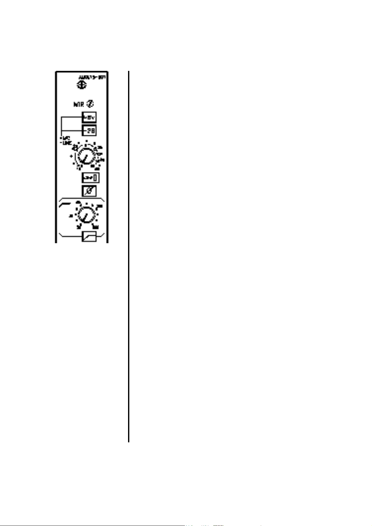
MTR
This sub-panel preset is for calibration of the external meter output
of the module.
48V
Provides phantom power for a condenser microphone, or DI box.
Optional balancing transformers may be fitted on the Mic input.
-20dB (PAD)
This inserts a 20dB attenuator in circuit with the Mic input. It may
be used when high-output microphones are employed, or for the
use of the Mic input for Line-level signals.
GAIN
The gain control is a wide range rotary potentiometer, and is active
on both Mic and Line Inputs. On Mic, the gain can be adjusted
from 12 to 66dB. For Line inputs, the adjustment is from -10 to
+20dB.
LINE
The LINE switch selects the signal on the line input socket to feed
the channel path when it is down. In this case, the Mic signal is
disconnected. The led illuminates when Line is selected.
PHASE
The PHASE REVERSE switch inverts the phase of the selected
input, to allow compensation for different wiring standards.
FILTER
The Filter switch inserts a tuneable highpass filter with a roll-off of
12dB per octave into circuit after the input amplifier. This may be
used to eliminate unwanted low-frequency noises such as rumble,
or camera buzz.
FILTER FREQUENCY CONTROL
The frequency range of the filter is continuously variable between
20Hz to 500Hz.
Q2 OPERA TION AND MAINTENANCE MANUAL 9601 20
Page 21
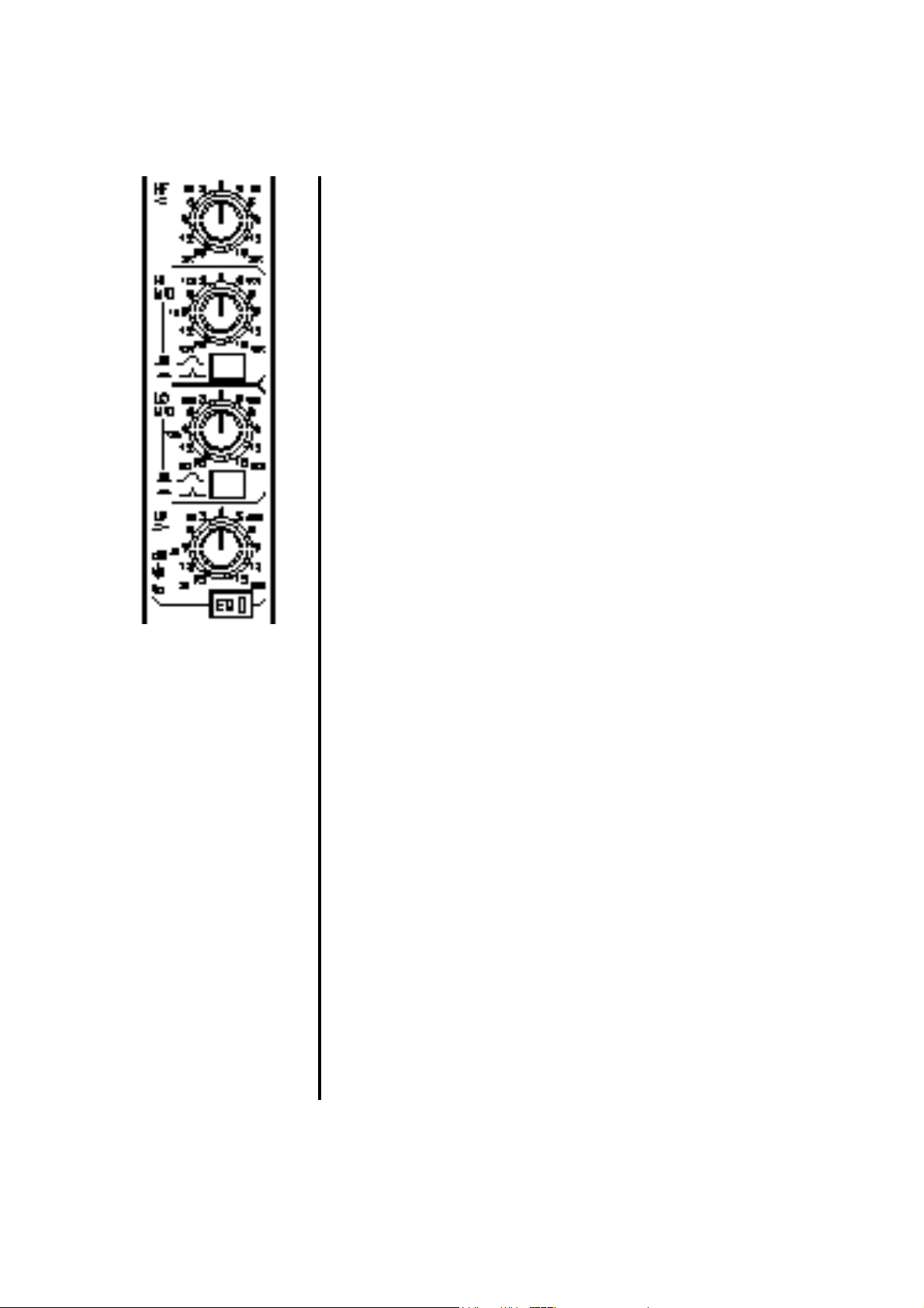
EQUALISER
The Q2 Equaliser is a four-band design, all bands having sweep
frequency adjustment. Each band consists of two dual-concentric
pots. The upper pot is the gain adjustment, the lower control being
the frequency adjustment. The two mid-range sections each have a
switch-selectable Q.
HF
Shelving section, providing +/-15dB of gain with an adjustable
frequency range of 2kHz to 20kHz.
HI MID
Peaking section, providing +/-15dB of gain, at frequencies from
525Hz to 15kHz.
Q
Selects the Q to be 0.9 or 1.8. The Q is 0.9 when the switch is in
the ‘down’ position.
LO MID
Peaking section, providing +/-15dB of gain, at frequencies from
80Hz to 2.2kHz.
Q
Selects the Q to be 0.9 or 1.8. The Q is 0.9 when the switch is in
the ‘down’ position.
LF
Shelving section, providing +/-15dB of gain with an adjustable
frequency range of 20Hz to 500Hz.
EQ IN
The EQ switch inserts the entire equaliser circuit into circuit.
When switched out, the equaliser is totally bypassed, keeping the
signal path to a minimum. The led in the switch illuminates when
the EQ is in circuit. The Insert point is normally located after the
EQ section, but a switch located on the module pcb allows the
insert to be pre-EQ.
Q2 OPERA TION AND MAINTENANCE MANUAL 9601 21
Page 22
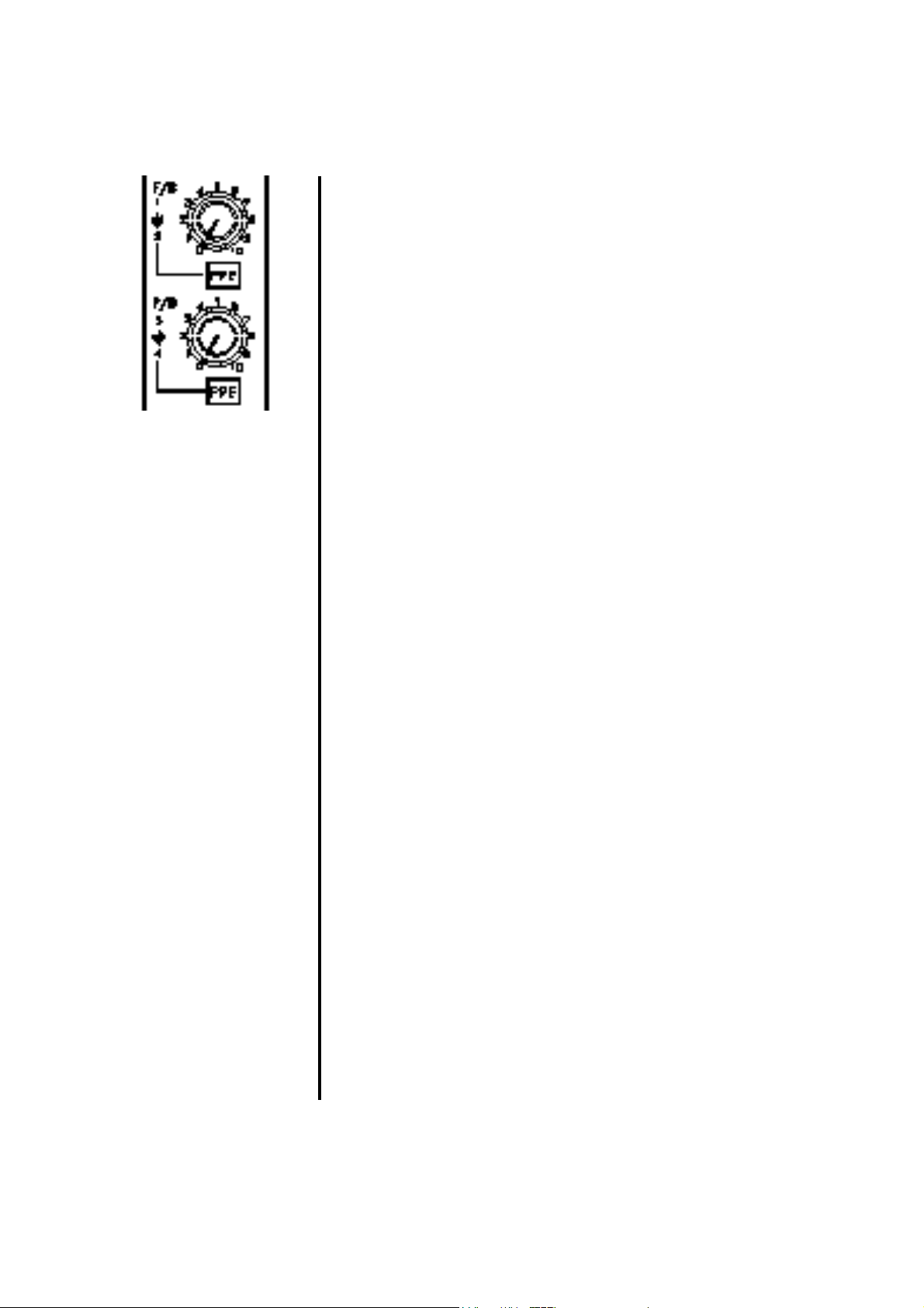
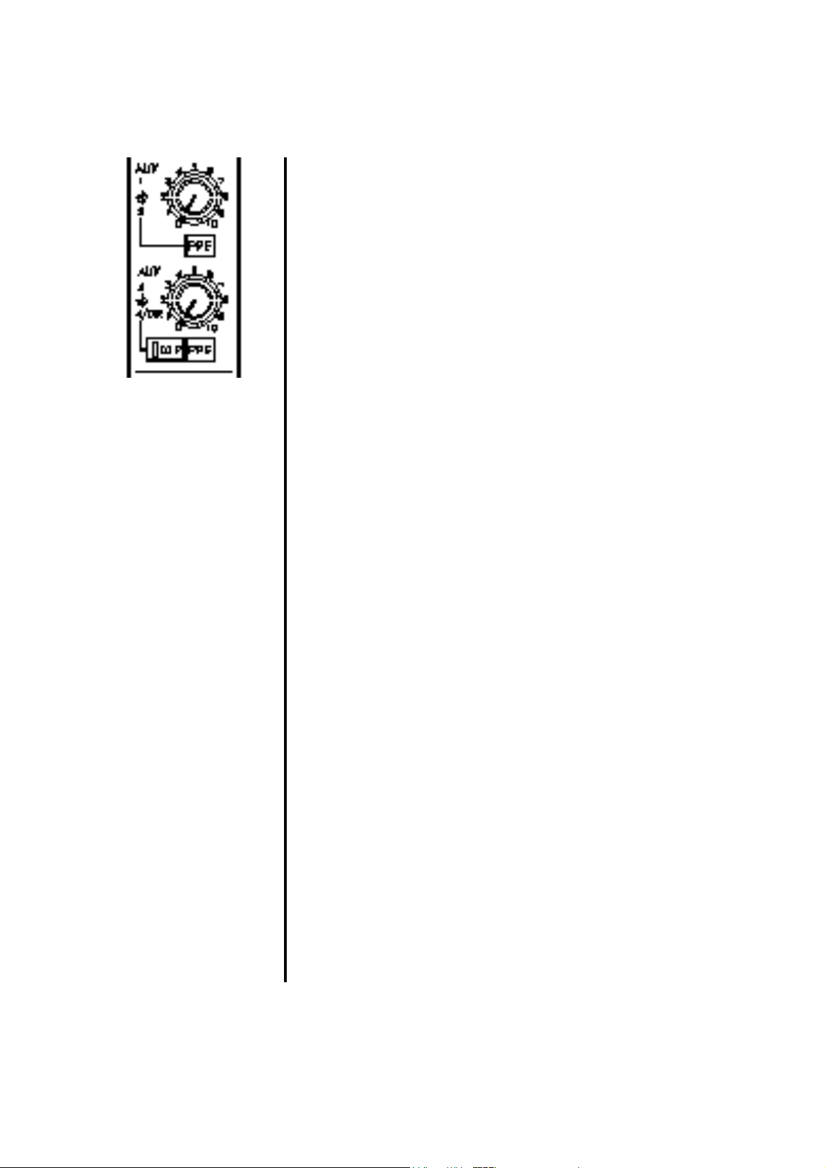
AUXILIARIES
Q2 has eight auxiliary buses, accessed on the Input module from 4
sets of dual-concentric controls. In addition, the channel direct
output may be controlled via one pot, to provide extended auxiliary
sends. For convenient assignment four of the auxiliary buses are
denoted as foldback buses.
F/B 1 (Foldback 1, upper control)
Controls the level of the channel signal fed to the Foldback 1 bus.
This signal is normally post-fader, unless the PRE button, just
below, is depressed. Internal links on the module pcb allow the
pre-fader feed to be pre or post-EQ (paired with F/B 2).
F/B 2 (Foldback 2, lower control)
Controls the level of the channel signal fed to the Foldback 2 bus.
This signal is normally post-fader, unless the PRE button, just
below, is depressed.
PRE
Selects the signal feed for Foldbacks 1 and 2 to be pre-fader rather
than post-fader.
F/B 3 (Foldback 3, upper control)
Controls the level of the channel signal fed to the Foldback 3 bus.
This signal is normally post-fader, unless the PRE button, just
below, is depressed. Internal links on the module pcb allow the
pre-fader feed to be pre or post-EQ (paired with F/B 4).
F/B 4 (Foldback 4, lower control)
Controls the level of the channel signal fed to the Foldback 4 bus.
This signal is normally post-fader, unless the PRE button, just
below, is depressed.
PRE
Selects the signal feed for Foldbacks 3 and 4 to be pre-fader rather
than post-fader.
Q2 OPERA TION AND MAINTENANCE MANUAL 9601 22
Page 23
AUX 1 (Upper control)
Controls the level of the channel signal fed to the Aux 1 bus. This
signal is normally post-fader, unless the PRE button, just below, is
depressed. Internal links on the module pcb allow the pre-fader
feed to be pre or post-EQ (paired with Aux 2).
AUX 2 (Lower control)
Controls the level of the channel signal fed to the Aux 2 bus. This
signal is normally post-fader, unless the PRE button, just below, is
depressed.
PRE
Selects the signal feed for Auxes 1 and 2 to be pre-fader rather than
post-fader.
AUX 3 (Upper control)
Controls the level of the channel signal fed to the Aux 3 bus.
This signal is normally post-fader, unless the PRE button, just
below, is depressed. Internal links on the module pcb allow the prefader feed to be pre or post-EQ (paired with Aux 4).
AUX 4 (Lower control)
Controls the level of the channel signal fed to the Aux 4 bus. This
signal is normally post-fader, unless the PRE button, just below, is
depressed.
PRE
Selects the signal feed for Auxes 3 and 4 to be pre-fader rather than
post-fader.
DIR
Re-routes the signal on the Aux 4 control to feed the Channel
Direct output. The signal no longer feeds the Aux 4 bus, and can
be used either as an additional single effects send, or as a feed to a
multitrack for example.
Note: Dir and Pre are local to the module, they do not affect the
signal flow on any other module than the one on which they are
located.
Q2 OPERA TION AND MAINTENANCE MANUAL 9601 23
Page 24

ROUTING AND STATUS
PAN
In normal mode and with the PAN set to centre, equal levels are
sent to both sides of the stereo mix or to ODD and EVEN groups
that are in use, with a 4.5dB drop relative to fully clockwise or anticlockwise. Setting the PAN control fully anticlockwise sends full
level to the Left bus, cutting the send to the Right bus; fully
clockwise rotation sends full level to the Right bus, cutting the
feed to Left.
L/R
Routes the post-fade, post-pan channel signal to the main stereo
mix bus, with led indication. The PAN control is automatically
inserted into circuit.
MONO
Routes the post-fade, post-pan channel signal to the main mono
mix bus, with led indication.
PAN
Switches the PAN control in circuit across odd and even group
buses, with led indication.
LCR
Changes the mode of the pan pot from conventional stereo (L/R
panning as described above to Left-Centre-Right mode. In this
mode, the pan control acts across all three main buses, using the
mono bus as a centre bus. When the pan is fully anti-clockwise,
signal is sent only to the left bus, with no signal to centre or right
buses. In the centre, signal is sent only to the centre (mono) bus,
with no signal to left or right buses. When fully clockwise, signal is
only sent to the right bus, with no signal sent to left or centre buses.
If a pair of groups (eg 1 and 2) is selected, the pan also acts in LCR
mode, but without a centre output from the groups unless the LCR
group modules are fitted.
11
Q2 OPERA TION AND MAINTENANCE MANUAL 9601 24
Page 25
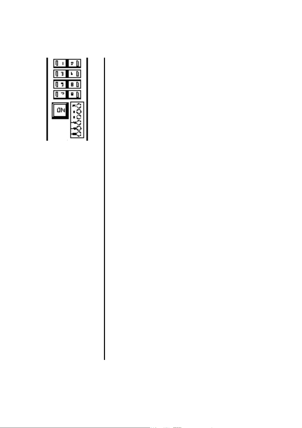
1
Routes the post-fade, post-pan channel signal to output bus 1, with
led indication.
2 ( and 3, 4, 5, 6, 7, 8)
Routes the post-fade, post-pan channel signal to output bus 2 (and
3, 4, 5, 6, 7, and 8 if pressed), with led indication.
ON
The ON switch enables the channel signal path, and is indicated by
an led in the switch when the channel is active. When OFF, all
post-fade auxiliary sends and routing assignments are muted.
Internal links allow the ON switch to be configured as a channel
CUT.
METER
The six segment led meter comprises a five segment meter, fed
from one of three points in the signal chain, and the PEAK led,
which is fed simultaneously from all 3 points, giving a warning of
potential overload signals within the signal path.
Q2 OPERA TION AND MAINTENANCE MANUAL 9601 25
Page 26
CUE
The CUE (or SOLO) button feeds a Pre-fader or post-fader signal
(as selected on the master module PFL or AFL) to the Monitor
section (loudspeakers or headphones), replacing the selected
monitor source if one is selected. The main stereo output of the
console is not affected unless SIP (Solo-in-place) mode has been
selected on the master . The yellow led in the CUE switch will flash
when the CUE function is active. CUE signals from different
sources that are active simultaneously in the non-interlocked mode
will be summed.
To latch the CUE function, press the button quickly and release. To
unlatch, repeat. To CUE a signal momentarily, hold down the CUE
button for at least 1 second. On release, the CUE will also be
released.
See THE CUE/SOLO SYSTEM on page 16 for full functional
details.
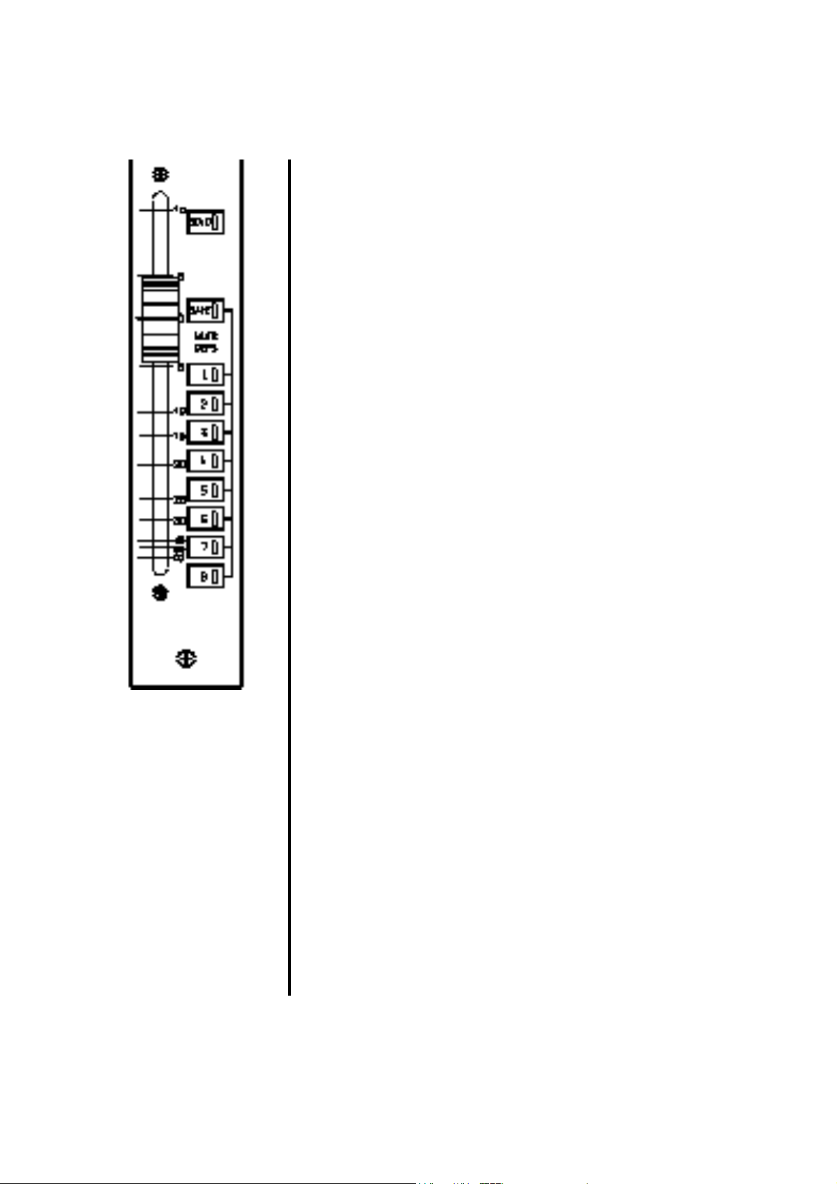
FADER
The fader is the main signal level control for the channel, and is a
long-throw type which gives smooth control of the channel level.
SAFE
Deselects the return from the VCA/MUTE Group system, without
affecting the mute group assignments. Useful to locally protect
signals, or manually override grouped MUTE ON conditions.
MUTE GROUP 1
Assigns the channel to MUTE Group 1. Similarly for MUTE
Groups 2 through 8.
Q2 OPERA TION AND MAINTENANCE MANUAL 9601 26
Page 27

CONNECTORS AND PIN ASSIGNMENTS
MIC INPUT :XLR type 3 pin connectors, Balanced
Nominal level : -56dBu to -8dBu
Pin 1 - Ground
Pin 2 - Signal +ve (hot)
Pin 3 - Signal -ve (cold)
Input impedance : >2k.
LINE INPUT :1/4" TRS Jack Socket, 'A' Guage, Balanced
Nominal Input Level : +4dBu
Tip : Signal +ve (Hot)
Ring : Signal -ve (Cold)
Sleeve: Ground
Input Impedance : >10 kOhm
INSERT SEND :
1/4" TRS Jack socket, ‘A’ Gauge, Balanced
Nominal Output level: +4dBu
Tip : Signal +ve (Hot)
Ring : Signal -ve (Cold)
Sleeve: Ground
Output Impedance: <75 Ohm
INSERT RETURN :
1/4" TRS Jack Socket, ‘A’ Gauge, Balanced
Nominal Input Level: +4dBu
Tip : Signal +ve (Hot)
Ring : Signal -ve (Cold)
Sleeve: Ground
Input Impedance : >10 kOhm
DIRECT OUTPUT : 1/4" TRS Jack socket, ‘A’ Gauge, Balanced
Nominal Output level: +4dBu
Tip : Signal +ve (Hot)
Ring : Signal -ve (Cold)
Sleeve: Ground
Output Impedance: < 75 Ohm
Q2 OPERA TION AND MAINTENANCE MANUAL 9601 27
Page 28

VCA INPUT MODULE
Q2 may also be supplied with 8 VCA/Mute groups. The input
module is essentially the same as the standard mono input, with the
addition of the 8 VCA/Mute groups, and mutes on most of the
auxiliary sends.
Replacing 4 input modules are the VCA master modules, which are
the fader and mute masters to control the 8 VCA/Mute groups.
Each module has 2 such masters, and a stereo effects return input.
Only the differences from the standard module are described here,
which are in fact all on the lower section of the module.
Q2 OPERA TION AND MAINTENANCE MANUAL 9601 28
Page 29

F/B 1/2 ON
Enables the channel feeds to the foldback buses 1 and 2.
F/B 3/4 ON
Enables the channel feeds to the foldback buses 3 and 4.
AUX 1/2 ON
Enables the channel feeds to the foldback buses 1 and 2.
EXT
This led illuminates when the channel is muted via an external
source, for example a noise gate control system using the channel
VCA. The remote control input accepts a DC voltage in the range
0 -10V. This facility is not available on current consoles, unless to
special order, although the led indicator has not been removed.
The wiring diagram overleaf should be followed to minimise noise
on the control lines when using external inputs.
MUTE SAFE (Not active on VCA consoles)
This may not be fitted to future production.
VCA/MUTE GROUP 1 ASSIGN
Assigns the channel mute to VCA/Mute Group 1, with led
indication. The channel level is now dependant on both the
position of the local fader and the position of the VCA master
fader. Similarly for assigns 2, 3, 4, 5, 6, 7 and 8.
Internal links allow the MUTE GROUPS to become SCENE
PRESETS, that is when a MASTER is pressed, all assigned
channels are switched ON, not muted.
Q2 OPERA TION AND MAINTENANCE MANUAL 9601 29
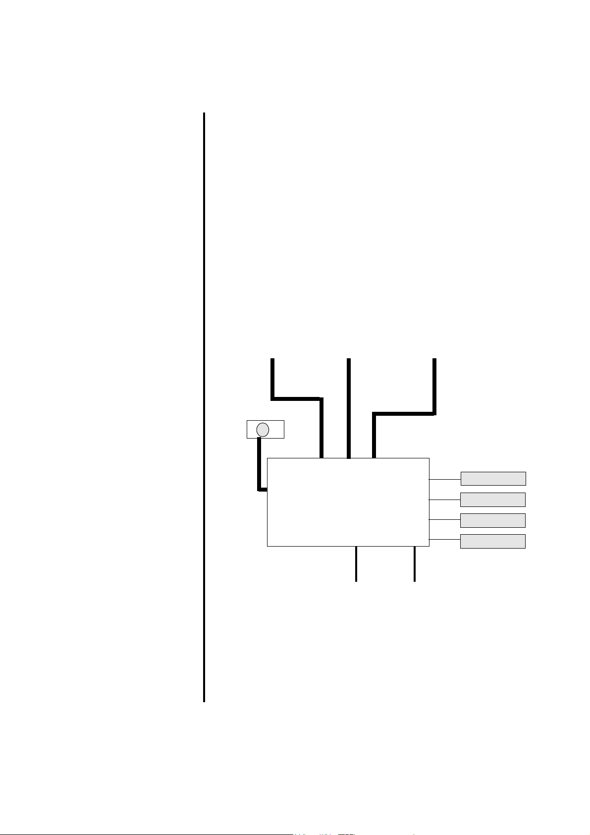
Page 30

EXTERNAL VCA
FADER CONTROL
WIRING
Q2 OPERA TION AND MAINTENANCE MANUAL 9601 30
Page 31

STEREO EFFECT RETURN MODULE
As an option, in place of a standard input, a stereo effect return
input may be fitted. The effect return section may be controlled by
the VCA master, if VCA/Mute subgrouping is fitted to the console.
GAIN
Adjusts the gain of the effect return input section. The gain is
adjustable from -15dB to +15dB.
L CUT
Cuts the signal feed to the left channel, with led indication.
R CUT
Cuts the signal feed to the right channel, with led indication.
PHASE REVERSE
Inverts the phase of the signal on the right channel input.
WIDTH
Varies the width of the stereo image from mono through normal
stereo to a wide signal where the left and right signals appear to
come from outside their normal image positions.
M/S DECODING
If the width is set fully anticlockwise to MONO and the PHASE
REVERSE switch is pressed the module will decode line level M/S
(Sum and Difference) signals. This may be the output of a
pre-amp, or recorded material.
Q2 OPERA TION AND MAINTENANCE MANUAL 9601 31
Page 32

HF EQ
A shelving equaliser with an adjustable gain of +/-15dB at a
frequency of 12kHz.
LF EQ
A shelving equaliser with an adjustable gain of +/-15dB at a
frequency of 50Hz.
F/B and AUXILIARY SENDS
F/B 1/2
This dual concentric pair of level controls adjusts the amount of
signal fed to foldback buses 1 and 2 (or 3 and 4 if the switch 3-4 is
pressed). The upper control adjusts the level for bus 1 (3), the
lower for bus 2 (4). Internal links allow these feeds to be selected
from a mono sum of the stereo signal, or left to 1, right to 2 (all
selectable pre or post fader by links).
3-4
The switch assigns the level controls to feed foldback buses 3/4
instead of 1/2.
AUX 1/2
This dual concentric pair of level controls adjusts the amount of
signal fed to auxiliary buses 1 and 2 (or 3 and 4 if the switch 3-4 is
pressed). The upper control adjusts the level for bus 1 (3), the
lower for bus 2 (4). Internal links allow these feeds to be selected
from a mono sum of the stereo signal, or left to 1, right to 2 (all
selectable pre or post fader by links).
3-4
The switch assigns the level controls to feed auxiliary buses 3/4
instead of 1/2.
Q2 OPERA TION AND MAINTENANCE MANUAL 9601 32
Page 33

BAL
Balances the stereo signal within the stereo bus, or within pairs of
groups if the MONO/STEREO button is set to STEREO.
MONO/STEREO
If set to MONO, a mono sum of the stereo signal is fed to any
selected group. If set to stereo, a stereo signal is sent to pairs of
groups via the BAL control, left to odd, right to even.
MONO
Assigns a MONO sum of the stereo signal to the main MONO
(Centre) bus.
L/R
Assigns the stereo signal to the main STEREO L/R bus.
1
Assigns signal to group 1, either as a mono sum, or the left channel,
depending on the setting of the mono stereo switch. Similarly for
groups 2-8.
Q2 OPERA TION AND MAINTENANCE MANUAL 9601 33
Page 34

SAFE (Not active on VCA modules)
Deselects the return from the MUTE Group system, without
affecting the mute group assignments. Useful to locally protect
signals, or manually override grouped MUTE ON conditions.
VCA/MUTE GROUP 1
Assigns the channel to VCA/MUTE Group 1. Similarly for VCA/
MUTE Groups 2 through 8. If the VCA option is fitted then the
post fader level will depend upon the local fader and the VCA
group master fader.
CUE
Assigns the stereo signal to the CUE system, with flashing led
indication when enabled.
ON
Enables the Effect Return signal path.
FADER
Controls the post fader signal level.
Q2 OPERA TION AND MAINTENANCE MANUAL 9601 34
Page 35

CONNECTORS AND PIN ASSIGNMENTS
LINE A : 3 Pin XLR type, Balanced
Nominal Input Level: +4dBu
Pin 2 : Signal +ve (Hot)
Pin 3 : Signal -ve (Cold)
Pin 1 : Ground
Input Impedance : >10 kOhm
LINE B : 1/4" TRS Jack Socket, ‘A’ Gauge, Balanced
Nominal Input Level: +4dBu
Tip : Signal +ve (Hot)
Ring : Signal -ve (Cold)
Sleeve: Ground
Input Impedance : >10 kOhm
Q2 OPERA TION AND MAINTENANCE MANUAL 9601 35
Page 36

MONO SUBGROUP OUTPUT MODULE
Either 8 or 16 mono subgroup modules may be fitted in Q2. If 16
are fitted, routing is paired, with active pan across the group buses
at all times. For 8 modules, routing is individually selected, with
pan only switched in across odd and even groups as required.
The module comprises the group control and output (lower part of
module) and a matrix mixer section (upper part of module).
Each module has controls for inputs to the Matrix mixer, ie they are
not feeds from that group to the matrix buses, but feeds from the
groups etc to the matrix.
F/B 1/3
Adjusts the level of the Foldback 1 master output (or 3) fed to the
Matrix bus on the module. This may be used to feed a global mix
set-up on the F/B 1 bus to any of the 8 matrix outputs.
F/B 3 (switch)
Selects the Foldback output 3 to the matrix instead of F/B 1.
F/B 2/4
Adjusts the level of the Foldback 2 master output (or 4) fed to the
Matrix bus on the module.
F/B 4 (switch)
Selects the Foldback output 4 to the matrix instead of F/B 2.
L/R
Adjusts the level of the summed (mono) signal from the main
stereo left and right outputs fed to the Matrix on the module.
MONO
Adjusts the level of the main Mono (centre) signal from the main
mono output fed to the Matrix on the module.
1
Adjusts the level of the post-fader Group 1 signal input to the
Matrix. Similarly for Controls 2-8 for Group signals 2 to 8.
Q2 OPERA TION AND MAINTENANCE MANUAL 9601 36
Page 37

T/B
Enables talkback signals to be routed to the Matrix output when the
communication system is used, with led indication. This can be
used to prevent talkback signals going to unwanted destinations.
ON
Enables the Matrix output, with led indication.
MATRIX METER
Sub-panel preset used to calibrate the Matrix level meter .
GROUP METER
Sub-panel preset used to calibrate the Group level meter.
CUE/SOLO
Solo’s the Matrix signal to the main monitors (headphones or
loudspeakers), with flashing led indication. See the Input Module
for a functional description of the solo button.
FADER
The 60mm fader controls the level of the Matrix output signal.
PAN
Pans the Group signal across the main Stereo bus, or if in LCR
mode across the Left, Right and Centre (mono) buses. In the
centre, in L/R mode, the signals are 4.5dB below the signals when
hard-panned left or right.
PAN (mode)
In the ‘up’ position the pan mode is conventional Stereo (L/R)
panning. In the ‘down’ position, the group is panned across the
three main outputs in Left-Centre-Right mode.
When the pan is fully anti-clockwise, signal is sent only to the left
bus, with no signal to centre or right buses. In the centre, signal is
sent only to the centre (mono) bus, with no signal to left or right
buses.
When fully clockwise, signal is only sent to the right bus, with no
signal sent to left or centre buses.
Q2 OPERA TION AND MAINTENANCE MANUAL 9601 37
Page 38

SUB/LCR
Routes the group signal to the main Stereo (Left/Right) and main
Mono (centre) buses, with led indication.
ON
The ON switch enables the group output, and is indicated by an
led in the switch when the output is active. Internal links allow the
ON switch to be configured as a group CUT.
MATRIX SEND PRE
Allows the Group input to the Matrix to be fed pre-fader, rather
than post-fader.
CUE/SOLO
Solo’s the Group signal to the main monitors (headphones or
loudspeakers), with flashing led indication. See the Input Module
for a functional description of the solo button.
MUTE SAFE (Not active in VCA consoles)
Prevents the Mute Group (or scene preset) master from muting the
channel, and may be used to locally override muted channels.
VCA/MUTE GROUP 1 ASSIGN
Assigns the channel mute to VCA/Mute Group 1, with led
indication. Similarly for assigns 2, 3, 4, 5, 6, 7 and 8. If the VCA
option is fitted then the channel level will depend upon the position
of the channel fader and the VCA group master.
Internal links allow the MUTE GROUPS to become SCENE
PRESETS, that is when a MASTER is pressed, all assigned
channels are switched ON, not muted.
Q2 OPERA TION AND MAINTENANCE MANUAL 9601 38
Page 39

CONNECTORS AND PIN ASSIGNMENTS
Group Ouptut : 3 Pin XLR type, Balanced
Nominal Output Level: +4dBu
Pin 2 : Signal +ve (Hot)
Pin 3 : Signal -ve (Cold)
Pin 1 : Ground
Output Impedance : <75 Ohm
Matrix Ouptut : 3 Pin XLR type, Balanced
Nominal Output Level: +4dBu
Pin 2 : Signal +ve (Hot)
Pin 3 : Signal -ve (Cold)
Pin 1 : Ground
Output Impedance : <75 Ohm
Insert Send : 1/4" TRS Jack socket, ‘A’ Gauge, Balanced
Nominal Output level: +4dBu
Tip : Signal +ve (Hot)
Ring : Signal -ve (Cold)
Sleeve: Ground
Output Impedance: <75 Ohm
Insert Return : 1/4" TRS Jack Socket, ‘A’ Gauge, Balanced
Nominal Input Level: +4dBu
Tip : Signal +ve (Hot)
Ring : Signal -ve (Cold)
Sleeve: Ground
Input Impedance : >10 kOhm
Q2 OPERA TION AND MAINTENANCE MANUAL 9601 39
Page 40

STEREO SUBGROUP OUTPUT MODULE
Eight stereo subgroup modules may be fitted in Q2, and routing is
individually selected.
The module comprises the Stereo Group control and output (lower
part of module) and a Stereo Matrix mixer section (upper part of
module). Each module has controls for inputs to the Stereo Matrix
mixer ie they are not feeds from that Group to the Matrix buses, but
feeds from the Groups etc to the Matrix.
F/B 1/3
Adjusts the level of the Foldback 1 master output (or 3) fed to the
Stereo Matrix bus on the module. This may be used to feed a global
mix set-up on the F/B 1 bus to any of the 8 Stereo Matrix outputs.
The control is a dual-concentric pair with Level and Pan adjust
across the Stereo Matrix.
F/B 3 (switch)
Selects the Foldback output 3 to the matrix instead of F/B 1.
F/B 2/4
Adjusts the level of the Foldback 2 master output (or 4) fed to the
Matrix bus on the module. The control is a dual-concentric pair
with Level and Pan adjust across the Stereo Matrix.
F/B 4 (switch)
Selects the Foldback output 4 to the matrix instead of F/B 2.
L/R
Adjusts the level of the main Stereo Left and Right outputs fed to
the Stereo Matrix on the module.
MONO
Adjusts the level of the main Mono (centre) signal from the main
Mono output fed to both sides of the Stereo Matrix on the module.
1
Adjusts the level of the post-fader Stereo Group 1 signal input to
the Stereo Matrix. Similarly for Controls 2-8 for Group signals 2 to
8.
Q2 OPERA TION AND MAINTENANCE MANUAL 9601 40
Page 41

T/B
Enables talkback signals to be routed to the Matrix output when the
communication system is used, with led indication. This can be
used to prevent talkback signals going to unwanted destinations.
ON
Enables the Matrix output, with led indication.
MATRIX METER (L and R)
Sub-panel preset used to calibrate the Stereo Matrix level meters.
GROUP METER (L and R)
Sub-panel preset used to calibrate the Stereo Group level meters.
CUE/SOLO
Solo’s the Stereo Matrix signal to the main monitors (headphones
or loudspeakers), with flashing led indication. See the Input
Module for a functional description of the solo button.
FADER
The 60mm fader controls the level of the Stereo Matrix output
signals.
Q2 OPERA TION AND MAINTENANCE MANUAL 9601 41
Page 42

BAL
Adjusts the Stereo Group signal within the main Stereo Left and
Right buses. The range of adjustment is +/-3dB.
SUB/LCR
Routes the Stereo Group signal to the main Stereo (Left/Right) bus,
and/or the main Mono (centre) buses, with led indication.
ON
The ON switch enables the group output, and is indicated by an
led in the switch when the output is active. Internal links allow the
ON switch to be configured as a group CUT.
MATRIX SEND PRE
Allows the Stereo Group input to the Stereo Matrix to be fed
pre-fader, rather than post-fader.
CUE/SOLO
Solo’s the Group signal to the main monitors (headphones or
loudspeakers), with flashing led indication. See the Input Module
for a functional description of the solo button.
MUTE SAFE (Not active on VCA consoles)
Prevents the Mute Group (or scene preset) master from muting the
channel, and may be used to locally override muted channels.
VCA/MUTE GROUP 1 ASSIGN
Assigns the channel mute to VCA/Mute Group 1, with led
indication. Similarly for assigns 2, 3, 4, 5, 6, 7 and 8. If the VCA
option is fitted then the channel level will depend upon the position
of the channel fader and the VCA group master.
Internal links allow the MUTE GROUPS to become SCENE
PRESETS, that is when a MASTER is pressed, all assigned
channels are switched ON, not muted.
Q2 OPERA TION AND MAINTENANCE MANUAL 9601 42
Page 43

CONNECTORS AND PIN ASSIGNMENTS
Group Output : 3 Pin XLR type, Balanced
Nominal Output Level: +4dBu
Pin 2 : Signal +ve (Hot)
Pin 3 : Signal -ve (Cold)
Pin 1 : Ground
Output Impedance : <75 Ohm
Matrix Output : 3 Pin XLR type, Balanced
Nominal Output Level: +4dBu
Pin 2 : Signal +ve (Hot)
Pin 3 : Signal -ve (Cold)
Pin 1 : Ground
Output Impedance : <75 Ohm
Insert Send : 1/4" TRS Jack socket, ‘A’ Gauge, Balanced
Nominal Output level: +4dBu
Tip : Signal +ve (Hot)
Ring : Signal -ve (Cold)
Sleeve : Ground
Output Impedance: <75 Ohm
Insert Return : 1/4" TRS Jack Socket, ‘A’ Gauge, Balanced
Nominal Input Level: +4dBu
Tip : Signal +ve (Hot)
Ring : Signal -ve (Cold)
Sleeve: Ground
Input Impedance : >10 kOhm
Q2 OPERA TION AND MAINTENANCE MANUAL 9601 43
Page 44

LCR SUBGROUP OUTPUT MODULE
The LCR Subgroup Output module has three outputs (for the left,
centre and right outputs from each group). It may be used with
either the normal input module or the dedicated LCR input module.
The module comprises the LCR Group control and output (lower
part of module) and a mono Matrix mixer section (upper part of
module). Each module has controls for inputs to the Matrix mixer
ie they are not feeds from that group to the matrix buses, but feeds
from the groups etc to the matrix.
F/B 1/3
Adjusts the level of the Foldback 1 master output (or 3) fed to the
Matrix bus on the module. This may be used to feed a global mix
set-up on the F/B 1 bus to any of the 8 matrix outputs.
F/B 3 (switch)
Selects the Foldback output 3 to the matrix instead of F/B 1.
F/B 2/4
Adjusts the level of the Foldback 2 master output (or 4) fed to the
Matrix bus on the module.
F/B 4 (switch)
Selects the Foldback output 4 to the matrix instead of F/B 2.
L/R
Adjusts the level of the summed (mono) signal from the main
stereo left and right outputs fed to the Matrix on the module.
MONO
Adjusts the level of the main Mono (centre) signal from the main
mono output fed to the Matrix on the module.
1
Adjusts the level a summed mono signal of the post-fader LCR
Group A (1) signal input to the Matrix. Similarly for Controls 2-4
for LCR Group signals B, C and D (2 to 4).
Q2 OPERA TION AND MAINTENANCE MANUAL 9601 44
Page 45

T/B
Enables talkback signals to be routed to the Matrix output when the
communication system is used, with led indication. This can be
used to prevent talkback signals going to unwanted destinations.
ON
Enables the Matrix output, with led indication.
MATRIX METER
Sub-panel preset used to calibrate the Matrix level meter .
GROUP METERS (L, C, R)
Sub-panel presets used to calibrate the LCR Group level meters.
CUE/SOLO
Solo’s the Matrix signal to the main monitors (headphones or
loudspeakers), with flashing led indication. See the Input Module
for a functional description of the solo button.
FADER
The 60mm fader controls the level of the Matrix output signal.
SUB/LCR
Routes the group signal to the main LCR Stereo (Left/Right) and
Centre (mono) buses, with led indication.
ON
The ON switch enables the group output, and is indicated by an
led in the switch when the output is active. Internal links allow the
ON switch to be configured as a group CUT.
MATRIX SEND PRE
Allows the Group input to the Matrix to be fed pre-fader, rather
than post-fader.
Q2 OPERA TION AND MAINTENANCE MANUAL 9601 45
Page 46

CUE/SOLO
Solo’s the Group signal to the main monitors (headphones or
loudspeakers), with flashing led indication. See the Input Module
for a functional description of the solo button.
MUTE SAFE (Not active in VCA consoles)
Prevents the Mute Group (or scene preset) master from muting the
channel, and may be used to locally override muted channels.
VCA/MUTE GROUP 1 ASSIGN
Assigns the channel mute to VCA/Mute Group 1, with led
indication. Similarly for assigns 2, 3, 4, 5, 6, 7 and 8. If the VCA
option is fitted then the channel level will depend upon the position
of the channel fader and the VCA group master.
Internal links allow the MUTE GROUPS to become SCENE
PRESETS, that is when a MASTER is pressed, all assigned
channels are switched ON, not muted.
Q2 OPERA TION AND MAINTENANCE MANUAL 9601 46
Page 47

CONNECTORS AND PIN ASSIGNMENTS
Group Output : 3 Pin XLR type, Balanced
Nominal Output Level: +4dBu
Pin 2 : Signal +ve (Hot)
Pin 3 : Signal -ve (Cold)
Pin 1 : Ground
Output Impedance : <75 Ohm
Matrix Output : 3 Pin XLR type, Balanced
Nominal Output Level: +4dBu
Pin 2 : Signal +ve (Hot)
Pin 3 : Signal -ve (Cold)
Pin 1 : Ground
Output Impedance : <75 Ohm
Insert Send : 1/4" TRS Jack socket, ‘A’ Gauge, Balanced
Nominal Output level: +4dBu
Tip : Signal +ve (Hot)
Ring : Signal -ve (Cold)
Sleeve: Ground
Output Impedance: <75 Ohm
Insert Return : 1/4" TRS Jack Socket, ‘A’ Gauge, Balanced
Nominal Input Level: +4dBu
Tip : Signal +ve (Hot)
Ring : Signal -ve (Cold)
Sleeve: Ground
Input Impedance : >10 kOhm
Q2 OPERA TION AND MAINTENANCE MANUAL 9601 47
Page 48

FOLDBACK MASTER MODULE
F/B 1 LEVEL
Adjusts the level of the Foldback 1 Master output signal.
ON
Enables the Foldback 1 Master output signal, with led indication.
CUE/SOLO
Solo’s the Foldback signal to the main monitors (headphones or
loudspeakers), with flashing led indication. See the Input Module
for a functional description of the solo button.
Foldbacks 2-4 are identical to Foldback 1 above.
Q2 OPERA TION AND MAINTENANCE MANUAL 9601 48
Page 49

AUXILIARY MASTER MODULE
AUX 1 LEVEL
Adjusts the level of the Auxiliary 1 Master output signal.
ON
Enables the Auxiliary 1 Master output signal, with led indication.
CUE/SOLO
Solo’s the Auxiliary signal to the main monitors (headphones or
loudspeakers), with flashing led indication. See the Input Module
for a functional description of the solo button.
Auxiliaries 2-4 are identical to Auxiliary 1 above.
MUTE GROUP MASTER 1
When pressed, mutes all channels and outputs assigned to MUTE
GROUP 1. MASTER MUTES 2-8 operate in a similar fashion for
MUTE GROUPS 2-8.
HEADPHONES/HEADSET OUTPUTS
Two pairs of headphones (impedance 200-600 Ohms) may be
plugged in to the module. A Clearcom-type headset may also be
connected, complete with boom microphone, on a 4-pin XLR
connector.
HEADPHONES LEVEL
Adjusts the level of the monitor signal in the headphone or headset,
independently of the main monitor level control.
ON
Switches on the headphone/headset outputs.
Q2 OPERA TION AND MAINTENANCE MANUAL 9601 49
Page 50

STEREO MASTER MODULE
SOLO METER
Indicates the level of the Solo signal in stereo.
PFL METER
Indicates the level of the PFL signal.
METER CALIBRATIONS
Sub-panel presets to calibrate all module and meterbridge master
meters.
PSU INDICATOR LEDs
Three led’s which indicate all DC voltages are present.
CUE MODE SIP
Selects the CUE mode to be SIP (Solo-in-Place). This mode does
not mute inputs when a channel or output is solo’ed. The main
output signal is replaced by the solo’ed signal, until the cue/solo is
cleared when the original signal is returned to the main outputs.
EXTERNAL TAPE INPUT
An external input is provided, for use as interval playback, or
effects input.
L/R
Assigns the Tape input to the main Stereo Left and Right Outputs.
MONO
Assigns the Tape input to the main Mono (Centre) Output.
TAPE PLAY LEVEL
Adjusts the level of the Tape Input.
Q2 OPERA TION AND MAINTENANCE MANUAL 9601 50
Page 51

INTERNAL SINEWAVE/NOISE GENERATOR
Q2 features an integral generator capable of producing a 1kHz
sinewave or pink noise for system testing and alignment.
PINK/1kHz
Selects the type of output from the generator. In the ‘up’ position,
the generator produces PINK noise, in the ‘down’ position a 1kHz
sinewave tone.
ON
Enables the generator, with led indication
OSC
Adjusts the level of the generator output.
GENERATOR/TALKBACK ASSIGN MATRIX
Both the internal generator and talkback system share a matrix of
assign switches to all outputs.
F/B 1-2, 3-4
Assigns the generator and/or talkback to Foldback buses 1 and 2
and 3 and 4 respectively .
AUX 1-2, 3-4
Assigns the generator and/or talkback to Auxiliary buses 1 and 2
and 3 and 4 respectively .
GROUPS
Assigns the generator and/or talkback to all the Group buses.
MTX
Assigns the generator and/or talkback to all the Matrix buses which
have their T/B assign buttons pressed.
L/R
Assigns the generator and/or talkback to the main Left and Right
outputs.
MONO
Assigns the generator and/or talkback to the main Mono (centre)
output.
Q2 OPERA TION AND MAINTENANCE MANUAL 9601 51
Page 52

MONITOR SECTION
Any of three sources may be fed to the monitoring section, in
addition to the CUE/SOLO signal. If no source is selected, nothing
is heard on monitors until a CUE/SOLO is pressed.
TAPE
Selects the Tape input as the monitor source.
L/R
Selects the main Stereo Left/Right output as the monitor source.
MONO
Selects the main Mono output as the monitor source.
If both L/R and MONO are pressed, monitoring is in true LCR
mode, ie three channel outputs for simulation of the main speaker
system. This facility is very useful when the console is located in a
screened booth in a Theatre.
MONITOR LEVEL
Adjusts the level of the monitor outputs.
MONO
Assigns the monitor outputs to the mono (centre) monitor output.
DIM
Reduces the level of the monitoring system by 20dB.
ON
Enables the monitoring system.
Q2 OPERA TION AND MAINTENANCE MANUAL 9601 52
Page 53

CUE/SOLO MASTER SECTION
PFL/AFL
Selects the Cue/Solo mode to be PFL, or AFL when the switch is
depressed.
TRIM
Adjusts the level of the Cue/Solo signal, most useful in the PFL
mode.
CUE INTLK
Interlock mode selection. In normal mode, Cues are additive. That
is any number of Cue buttons may be pressed and the signals will
be added. In INTERLOCK mode, only one Cue may be active at
any time, so pressing a Cue will automatically cancel the
previously selected Cue.
CUE I/P
Indicates that an input CUE is pressed. Inputs take priority over
outputs in normal mode, so pressing an input CUE will suspend an
output CUE until the input is released.
CUE O/P
Indicates that an output CUE is pressed. This led will extinguish if
an input CUE is pressed while an output CUE is already active.
CUE RESET
Clears all pressed CUE buttons.
Q2 OPERA TION AND MAINTENANCE MANUAL 9601 53
Page 54

TALKBACK SYSTEM
In addition to the normal talkback microphone input, Q2 includes a
Clearcom-type communications interface.
S/TONE
Sub-panel preset for adjusting the sidetone of the Clearcom
compatible interface. Sidetone is the level of your own voice that
you will hear in the headphones when speaking into the
communications microphone. Some sidetone is usually preferred
as it gives confidence that the system is working.
T/B LEVEL
Adjusts the level of the talkback microphone system.
COMMS ON
Enables the communication system.
CALL
The led in the switch illuminates when the console is being called.
Alternatively, pressing CALL sends out a call signal to the Master.
TB
Pressing TB (Talkback) routes the talkback signal to all assigned
outputs.
Q2 OPERA TION AND MAINTENANCE MANUAL 9601 54
Page 55

MASTER OUTPUT CONTROL
PRE
Allows the signal feed from the main Left/Right outputs to the
Mono (Centre) output to be pre-fader rather than post-fader.
L/R TO MONO
Assigns the post-fader Left/Right Output to the main Mono
(Centre) output.
L/R CUE/SOLO
Solo’s the main Left/Right output to the main monitors
(headphones or loudspeakers), with flashing led indication.
MONO CUE/SOLO
Solo’s the main Mono (Centre) output to the main monitors
(headphones or loudspeakers), with flashing led indication.
FADERS
Three faders control the output level of the main Left, Right and
Centre (mono) signals. The user may determine the configuration
of the faders to be L, C, R or L, R, C.
Q2 OPERA TION AND MAINTENANCE MANUAL 9601 55
Page 56

MASTER CONNECTOR PANEL
CONNECTORS AND PIN ASSIGNMENTS
Main Left, Right and Mono Outputs,
Monitor Outputs, Auxiliary Outputs,
and generator output :
3 Pin XLR type, Balanced
Nominal Output Level: +4dBu
Pin 2 : Signal +ve (Hot)
Pin 3 : Signal -ve (Cold)
Pin 1 : Ground
Output Impedance : <75 Ohm
Mix Insert Send :
1/4" TRS Jack socket, ‘A’ Gauge, Balanced
Nominal Output level: +4dBu
Tip : Signal +ve (Hot)
Ring : Signal -ve (Cold)
Sleeve: Ground
Output Impedance: <75 Ohm
Mix Insert Return :
1/4" TRS Jack Socket, ‘A’ Gauge, Balanced
Nominal Input Level: +4dBu
Tip : Signal +ve (Hot)
Ring : Signal -ve (Cold)
Sleeve: Ground
Input Impedance : >10 kOhm
Talkback Microphone Input :
3 pin XLR type, Balanced
Nominal Input Level: -62dBu to -8dBu
Pin 2 : Signal +ve (Hot)
Pin 3 : Signal -ve (Cold)
Pin 1 : Ground
Input Impedance : >2 kOhm
+48V Phantom power optional
Tape Play Input :
3 Pin XLR type, Balanced
Nominal Input Level: +4dBu
Pin 2 : Signal +ve (Hot)
Pin 3 : Signal -ve (Cold)
Pin 1 : Ground
Input Impedance : >10 kOhm
Q2 OPERA TION AND MAINTENANCE MANUAL 9601 56
Page 57

VCA MASTER MODULE
The effect return VCA master is only fitted to consoles with the
optional VCA Grouping inputs. The effects return section may be
controlled by the VCA masters.
GAIN
Adjusts the gain of the effect return input section. The gain is
adjustable from -15dB to +15dB.
L CUT
Cuts the signal feed to the left channel, with led indication.
R CUT
Cuts the signal feed to the right channel, with led indication.
PHASE REVERSE
Inverts the phase of the signal on the right channel input.
WIDTH
Varies the width of the stereo image from mono through normal
stereo to a wide signal where the left and right signals appear to
come from outside their normal image positions.
M/S DECODING
If the width is set fully anticlockwise to MONO and the PHASE
REVERSE switch is pressed the module will decode line level M/S
(Sum and Difference) signals. This may be the output of a
pre-amp, or recorded material.
HF EQ
A shelving equaliser with an adjustable gain of +/-15dB at a
frequency of 12kHz.
LF EQ
A shelving equaliser with an adjustable gain of +/-15dB at a
frequency of 50Hz.
Q2 OPERA TION AND MAINTENANCE MANUAL 9601 57
Page 58

F/B and AUXILIARY SENDS
F/B 1/2
This dual concentric pair of level controls adjusts the amount of
signal fed to foldback buses 1 and 2 (or 3 and 4 if the switch 3-4 is
pressed). The upper control adjusts the level for bus 1 (3), the
lower for bus 2 (4). Internal links allow these feeds to be selected
from a mono sum of the stereo signal, or left to 1, right to 2 (all
selectable pre or post fader by links).
3-4
The switch assigns the level controls to feed foldback buses 3/4
instead of 1/2.
AUX 1/2
This dual concentric pair of level controls adjusts the amount of
signal fed to auxiliary buses 1 and 2 (or 3 and 4 if the switch 3-4 is
pressed). The upper control adjusts the level for bus 1 (3), the
lower for bus 2 (4). Internal links allow these feeds to be selected
from a mono sum of the stereo signal, or left to 1, right to 2 (all
selectable pre or post fader by links).
3-4
The switch assigns the level controls to feed auxiliary buses 3/4
instead of 1/2.
Q2 OPERA TION AND MAINTENANCE MANUAL 9601 58
Page 59

BAL
Balances the stereo signal within the stereo bus, or within pairs of
groups if the MONO/STEREO button is set to STEREO.
MONO/STEREO
If set to MONO, a mono sum of the stereo signal is fed to any
selected group. If set to stereo, a stereo signal is sent to pairs of
groups via the BAL control, left to odd, right to even, groups.
MONO
Assigns a MONO sum of the stereo signal to the main MONO
(Centre) bus.
L/R
Assigns the stereo signal to the main STEREO L/R bus.
1
Assigns signal to group 1, either as a mono sum, or the left channel,
depending on the setting of the mono stereo switch. Similarly for
groups 2-8.
ON
Enables the Effect Return signal path.
SAFE
Deselects the return from the VCA/MUTE Group system, without
affecting the mute group assignments. Useful to locally protect
signals, or manually override grouped MUTE ON conditions.
VCA/MUTE GROUP 1
Assigns the channel to VCA/MUTE Group 1. Similarly for VCA/
MUTE Groups 2 through 8.
CUE
Assigns the stereo signal to the CUE system, with flashing led
indication when enabled.
FADER
Controls the level of the EFFECT RETURN section of the module.
Q2 OPERA TION AND MAINTENANCE MANUAL 9601 59
Page 60

VCA MASTER SECTION
CUT 1
Mutes all channels assigned to VCA/MUTE Group 1. Similarly for
for CUT 2 through 8.
VCA 1
Switches in the VCA master fader to control VCA/Mute Group 1.
If the VCA is not switched in, the VCA control reverts to a fixed
unity gain setting. This is useful for quickly resetting all inputs to
their nominal gains (as set on their individual faders).
VCA MASTER FADER (100mm)
Controls the overall level of all the channels assigned to that group.
Q2 OPERA TION AND MAINTENANCE MANUAL 9601 60
Page 61

CONNECTORS AND PIN ASSIGNMENTS
LINE A : 3 Pin XLR type, Balanced
Nominal Input Level: +4dBu
Pin 2 : Signal +ve (Hot)
Pin 3 : Signal -ve (Cold)
Pin 1 : Ground
Input Impedance : >10 kOhm
LINE B : 1/4" TRS Jack Socket, ‘A’ Gauge, Balanced
Nominal Input Level: +4dBu
Tip : Signal +ve (Hot)
Ring : Signal -ve (Cold)
Sleeve: Ground
Input Impedance : >10 kOhm
Q2 OPERA TION AND MAINTENANCE MANUAL 9601 61
Page 62

Q2 TECHNICAL DESCRIPTION
THE AUDIO
MASTER MODULE
This consists of two main boards and one sub board. The sub
board carries the balanced tape inputs, balanced mix outputs,
balanced Left, Centre and Right monitor outputs and the Left AFL
Meter. The tape signals are fed down to the audio master board
while the mix and monitor outputs are fed in to the sub board from
the master board.
The main audio board carries the Right AFL meter and the main
circuitry for the Left, Centre and Right outputs of the console in
addition to the monitoring functions.
Typically the signal path from the left mix bus to the mix output is
as follows. The signal from the LEFT bus is mixed in a virtual
earth amplifier and immediately after this the LMIXPRE signal is
taken to other parts of the circuit. The signal then passes through
an SSM2404 switch which operates as a changeover to allow SIP
signals onto the signal path in place of the mix signal. Following
this an SSM2142 is used to send a balanced insert send signal to the
send jack which is normalled to the return jack. From here the
signal passes through an SSM2143 balanced to unbalanced stage to
the main fader (one each for Left Centre and Right). A fader buffer
stage follows after which the signal is fed up to the sub board to the
main mix outputs of the console. The signal is known as LMIX at
this point. A further buffer stage follows and the signal is then
known as LEFTMIX which goes to the matrix link connector. The
MIXL signal, in addition to going to the sub board connects to the
PRE switch which allows either a mix pre or post fade signal to be
selected as the source for the centre mix when mix left and right are
assigned to it. The combined signal is fed onto the CMIX bus.
The Left Right and Centre PRE signal derived immediately after
the mix amplifiers is used for SOLO and PFL and is fed via
SSM2404s onto the solo buses. A switch selects PFL or AFL
operation while a further switch located towards the top of the
module is used to select SIP operation. The output of the PFL/AFL
switch feeds the AFL meters which are mounted on the module
before entering the monitoring system via an SSM2404. A SOLO
TRIM pot can be used to alter the PFL solo level although it will
not of course change the level shown on the meter. The external
feeds to the meterbridge are permanently tied to the mix outputs of
the console.
Q2 OPERA TION AND MAINTENANCE MANUAL 9601 62
Page 63

A rotary pot is used to control the monitor outputs although not
directly. A control voltage is derived from the pot which is fed to
three VCAs on the sub board which control the monitor levels for
Left, Centre and Right. The monitor has associated MONO, DIM
and ON buttons and can be selected to carry CUE, TAPE, L/R and
Centre signals. If both the L/R and CENTRE buttons are depressed
then L C R monitoring will result. If no buttons are depressed then
CUE will be selected. Headphone monitoring is also available and
the left and right headphone feeds have the centre channel mixed in
with them. The headphones receive the same feed as the monitor
outputs of the console.
SIP monitoring uses the main mix outputs of the console in order
that an output solo does not cut the inputs assigned to that group
and the SIP signals enter the signal chain immediately before the
insert send points for the Left, Centre and Right mixes.
A RESET button disables any active cues on the console without
having to locate the soloed channel. The solo function is also
available for the L/R and Mono outputs of the console. A further
section of logic is associated with the solo function and the
operation is as follows.
First of all it is necessary to understand that input priority is the
normal condition in which any input solo will cancel an output solo
for its duration. Multiple input and output solos can be active in
this mode. Interlock mode means that only one solo in the console
can be active at any time. The reset button can be used to clear the
last required solo.
Consider first of all an input solo in the input priority condition.
The solo makes the output of IC44 pin 1 go low causing TR1 to
switch on which in turn causes TR2 to switch on giving INPUT
SOLO indication. Pin 7 of IC44 will go high as it will invert the
low from pin 1 causing TR4 to switch on which in turn switches
TR8 on. The causes the RESET line to stay in a high condition
which disables the solos on the output modules.
Q2 OPERA TION AND MAINTENANCE MANUAL 9601 63
Page 64

Further input solos can be added and the reset button can be used to
cancel them. If a solo is to be cancelled from the master reset
button then a positive voltage is fed to the base of TR9 to switch it
on causing the reset line to go low. Some means must be used to
turn off TR8 as otherwise the Vdd and Vss rails would be shorted
together and TR3 is turned on to prevent this from occurring.
In the INTERLOCK position of the switch pin 1 of IC44 is also fed
to IC45 which is configured as a virtual earth mixer. Pin 7 of IC45
will thus go high and be applied to the voltage comparator IC46.
With only one solo active this comparator will not operate and the
output will remain low. When a second solo is received then pin 1
of IC44 will rise higher in voltage causing pin 7 of IC45 to rise
which in turn will cause the voltage comparator to operate giving a
reset via TR9. Of course solos can still be cancelled on the
modules on which they are active. The same is true for output
solos which enter via IC45 and are mixed with the input solos
before reaching the voltage comparator. A reset can thus be
generated by requesting another solo or by operating the master
reset.
The solo circuits on the input and output modules are a little
complex and will be explained in the relevant sections.
The second main board is the COMMS board and as the name
suggests this board handles talkback and related functions. The Q2
is fitted with a CLEARCOM communication interface which is a
three wire system carrying DC signalling and two way audio. The
PFL meter is located on this board along with the external meter
drives and their associated trimmers.
The oscillator can generate either 1kHz or pink noise whose level
can be controlled by a pot. The talkback and oscillator can be
routed to foldback, auxiliaries, groups, matrix, L/R mix and Mono
outputs. To talk to the matrix a further switch must be pressed on
the required output module.
Q2 OPERA TION AND MAINTENANCE MANUAL 9601 64
Page 65

The talkback microphone amplifier is adjustable in level from a
front panel control and can be routed to the same destinations as the
oscillator in addition to the CLEARCOM interface. Incoming
communication from the CLEARCOM interface can be routed to
the monitor system by use of the COMMS ON key.
A SIDETONE trimmer allows the level of sidetone to be adjusted.
This is the amount of your voice that you will then hear in the
headphones when using the CLEARCOM system. IC6A is used to
amplify incoming communications and to reject outgoing talkback
which travels on the same wire as the incoming talkback. PR6
alters the rejection and hence the sidetone can be increased or
decreased. When talkback is used a DIM command is sent to the
main board. Talkback audio is also incoming from the headset and
this is fed to the CLEARCOM interface together with any audio
from the console talkback microphone.
The COMMS ON switch has several functions as follows:_
To allow incoming talkback onto the monitor system by operating
an electronic switch and passing audio over to the main board.
Allowing either the talkback microphone or the output of the
CLEARCOM system to go to talkback routing.
Routing the talkback microphone to the CLEARCOM system.
Putting a call out on the CLEARCOM system.
Also located on the COMMS board are the FLASH oscillator for
flashing lamps and the MONO solo switch circuit.
Q2 OPERA TION AND MAINTENANCE MANUAL 9601 65
Page 66

THE AUXILIARY MASTER MODULE
This board contains the master sections for the auxiliary outputs of
the console in addition to headphone amplifiers and a talkback
microphone amplifier for the headset microphone.
The 4 auxiliaries are identical and therefore it is only necessary to
describe one. The signal from the bus is mixed by IC1 and is then
passed through the fader followed by the ON switch to an
SSM2142 balanced line driver which connects to the rear panel on
the console. A feed for the meters and the solo system is taken
immediately after the ON switch. There are headphone amplifiers
for the front panel headphone sockets and another amplifier to feed
the headset. A separate talkback amplifier exists for the headset
microphone and this is fed to the COMMS board.
Q2 OPERA TION AND MAINTENANCE MANUAL 9601 66
Page 67

THE FOLDBACK MASTER MODULE
This contains the four master foldback sections which are identical
to the auxiliary master sections. A matrix link connector takes the
foldback outputs across to the output modules for use on the
matrices.
Q2 OPERA TION AND MAINTENANCE MANUAL 9601 67
Page 68

THE INPUT MODULE
THE SIGNAL PATH
The Q2 is equipped with a microphone and a line input selected by
a switch and controlled by the same pot. The microphone input
may have a 20dB pad switched in and a phantom supply can be fed
to the microphone from each module. From here the signal enters
or by-passes a phase reverse circuit which is simply a unity gain
inverting stage. The signal then enters or by-passes the sweepable
high pass filter. At this point the equaliser can be selected pre or
post the insert point and from here the signal enters the cut SSM
followed by the fader, the fader buf fer stage and the pan circuit
before going to the routing switches. A VCA version of the
module will allow for VCA level control and VCA muting.
THE RESET CIRCUIT.
A reset for the module logic is given by the RC network formed by
C41 and R142. On power up C41 will charge through R142
causing TR1 to switch on. This applies a low to the SET input of
the flip flop and a high to the reset input causing Q bar to go high
giving a channel ON condition. The RESET line is also fed to the
SOLO enable circuit.
THE SOLO SYSTEM
The Q2 solo system is a little more comprehensive than in other
consoles and there are some novel features about the way in which
it operates.
The SOLO button can be pressed fleetingly and the solo will latch
until the button is pressed for a second time. If the button is
depressed for a longer period then the solo will not latch but will
release as the solo button is released. There is also a facility for all
solos to be cleared by the operation of a master button on the
console.
The heart of the system is IC11 a dual D-Type flip flop. Normally
the reset pin will be held low and under this condition the state of
the Q output will toggle with each operation of the solo switch.
Q2 OPERA TION AND MAINTENANCE MANUAL 9601 68
Page 69

If the solo switch is held down then C43 will charge through D13
and R155 causing pin 1 of IC12 to go high. Pin 2 is already high as
the flip flop has operated to give a solo and thus pin 3 of IC12 will
go low. This low is applied to pin 2 of IC13 and when the solo
button is released pin 1 will also go low. Pin 3 of IC13 then goes
high causing the flip flop to be reset thus cancelling the solo. TR6
is also switched on to discharge C43. The output of IC12 will then
revert to a high state causing the reset to go low and allow normal
operation of the flip flop. A RESET signal from the master module
will be received by pin 2 of IC13 and will cause pin 3 to go high
(since pin 1 will already be low) again giving a reset and cancelling
any solo.
Another version of the above circuit exists based around 4001 OR
gates although the principle behind it is exactly the same. The
example shown is an output solo and in order for the input priority
system to work then an extra gate is used - IC47D. When a solo is
requested audio is allowed onto all four solo buses with selection
being made on the master module depending upon the selected solo
mode.
The RESET line from the master module is in fact tri-state and in
the high condition it is used to pull pin 11 of IC47D low cancelling
the solo. This only occurs when input priority mode is selected and
when an input solo is called for. The RESET does not reset the
output solo latch so that when cancelled the previous output solo
can again take effect. When the RESET line goes high it will go to
almost the audio positive rail. This excess voltage is removed by
zener diode D50 which is used to block the output of IC47B which
will be at 5V. When the RESET line goes low then IC48A will be
reset cancelling any solo.
Q2 OPERA TION AND MAINTENANCE MANUAL 9601 69
Page 70

Q2 PANNING
The Q2 console can exploit either L-R panning or L-C-R panning
selected by a switch. In either case the same components are
employed as follows.
The pan pot VR7 is centre tapped and under normal operation the
input signal is fed to the top of the pot (the hot end). This is
connected to the centre tap by a 10k resistor to give the appropriate
law and the wiper signals are fed to the pan buffer IC9. These
signals leave the module as LSUB or RSUB to give normal stereo
panning. The MIXC output is directly connected to the (mono)
input of the pan pot. The CGROUP output is grounded.
If the switch is depressed to give L-C-R panning then the centre
taps of the pots are grounded meaning that the pots will only work
across half of their range which is the required condition. The
signal can now leave as LSUB or RSUB or indeed PANL and
PANR if link 22 is installed in an LCR console. The output of the
pan buffers are combined by IC10A along with an out of phase feed
of the input signal to give a centre signal which is fed out as
CGROUP or MIXC.
A signal panned fully left will appear at the LEFT output only, a
CENTRE panned signal will appear on the centre output only and
of course a RIGHT panned signal will appear on the right output
only. A signal panned for example between left and centre will
have no output on the right output whereas it would if normal
stereo panning was employed.
Q2 OPERA TION AND MAINTENANCE MANUAL 9601 70
Page 71

ON/CUT CIRCUIT
The ON circuit of an input module is based around IC11 a dual,
positive edge triggered S/R Flip Flop. Under static conditions C40
will charge through R140 holding the clock input low. Pressing the
ON switch applies Vdd to the clock input causing pin 2 to be
clocked through to pin 1 reversing the states of Q and Q bar. For
the channel to be on Q bar should be high. Assuming that the
channel is SAFE at the moment then pin 10 of IC12 will go low
causing pin 11 to go high. Following this through the ON LAMP
link TR3 will be switched off by this high causing TR5 to be off
which means that the LED will be ON. An anti phase feed is taken
to the series and shunt FETs such that in the ON condition the
series FET receives a high while the shunt FET receives a low.
An alternative is for the lamp to indicate the CUT condition. A
local channel CUT will set Q bar low and thus pin 10 of IC12 will
be high. This will cross the cut lamp link and switch TR3 off
causing the LED to come on indicating a mute. At this time Q is
high causing pin 4 of IC13 to be low and therefore pin 6 of IC12 to
be low. If the channel is not locally cut but an external cut is
received from one of the master cut switches Q will be low and the
external cut signal will put a low on to pin 6 of IC13. Pin 4 will
thus go high and allow the FLASH signal to blink the CUT lamp if
LK9 is installed. The external cut is also applied to pin 8 of IC12
causing pin 10 to go high to operate the FETs and the lamp. Thus a
flashing cut lamp is an indication that a remote cut has been
received.
Q2 OPERA TION AND MAINTENANCE MANUAL 9601 71
Page 72

THE MIDI INTERFACE.
A cut is also possible from a midi muting system and this operates
on the flip flop by setting Q high and Q bar low from the same
signal which is inverted at TR2. The cut is a high on pin 2 of
CON8. The local cut switch is connected to pin 1 of CON8 to feed
a cut to the midi system.
Q2 OPERA TION AND MAINTENANCE MANUAL 9601 72
Page 73

Q2 ROUTING
There are 20 buses available in the Q2 console giving rise to
several possibilities. An input module can be configured to route to
8 mono groups, 16 mono groups with paired routing, 8 stereo sub
groups or 4 LCR groups. The following tables can be used to
check which links and resistors should be installed for the different
configurations.
INPUT MODULE RESISTORS
Resistor Standard/LCR Stereo/Mono 16
94 *
98 *
102 *
189 *
227 *
91 *
228 *
95 *
229 *
99 *
230 *
186 *
Q2 OPERA TION AND MAINTENANCE MANUAL 9601 73
Page 74

INPUT MODULE ROUTING LINKS
LK Mono Stereo LCR
6 *
20 *
21 *
22 *
23 *
24 *
25 *
26 *
27 *
28 *
31 *
32 * *
33 *
34 * *
35 *
36 * *
37 *
38 * *
THE LEVEL METER
The peak LED operates independently from the remainder of the
meter and is wired to three points as follows:-
Pre EQ
Post EQ
Post fader
Thus a high level on any of the three points may bring the peak
LED on. The main meter can be wired to any one of the three
points to indicate the desired level and is normally linked to the pre
equaliser signal.
Q2 OPERA TION AND MAINTENANCE MANUAL 9601 74
Page 75

FOLDBACK and AUXILIARIES
The Foldbacks and Auxiliaries can be switched pre or post fader.
In the pre fade position the signal can be sourced pre or post the
equaliser or post cut switch. Auxiliary 4 can be switched to control
the direct output which is normally post fader. The VCA version of
the console incorporates on/off switches for the auxiliary and
foldback sends which are mounted on the sub board. The sub
board connector is removed and replaced by links in a non VCA
console.
INPUT MODULE LINKS
Link Function
1, 2 Transformer Bypass
3, 4, (5) External Meter Pre EQ, Post EQ, Dir
7 Cut Lamp
(8) On Lamp
9 Cut Lamp Flash
(10) Link for non VCA version
(11), 12, 13 Internal Meter Pre EQ, Post EQ, Post
(14), 15, 16 Foldback Pre Pre EQ, Post EQ, Post Cut
(17), 18, 19 Auxiliary Pre Pre EQ, Post EQ, Post Cut
(29), 30 Mute, Scene
( ) Factory Position
Q2 OPERA TION AND MAINTENANCE MANUAL 9601 75
Page 76

THE MONO GROUP OUTPUT MODULE
This module contains the circuit for one group output and one
matrix output. The signal path for the group signal is from the bus
through the appropriate link depending upon which group the
module is programmed to receive into the bus mixing amplifier.
The signal then is fed to the balanced insert send output by an
SSM2142 and returned by an SSM2143 before entering the
SSM2402 used for the cut function. From here the signal passes
through the fader which has 10dB of gain in hand followed by the
fader buffer to make up the 10dB of gain. The signal is then
balanced in an SSM2142 to become the group output signal. The
group signal can be sub mixed to the main LCR bus and this can be
done in stereo or full LCR if selected.
The matrix send can be taken pre or post fade and in the pre fade
position it can be link programmed to be either pre or post mute.
The signal is then buffered and sent onto the matrix buses. The
matrix operates differently to previous DDA matrices and a full
level signal is sent to all buses. Thus the matrix pots are controlling
signal coming into their module as opposed to the previous
situation where the pots would control the level going to another
matrix output. The matrix signals are picked up, level controlled
and mixed together before going to the matrix ON switch. In
addition to the eight send signals the foldback, mix left/right and
mix centre signals are available on the matrix. Immediately after
the ON switch talkback is injected although the enable switch must
be operated for this to happen. The signal is then balanced in an
SSM2142 to become the matrix out signal.
Both the matrix and the group signals can be soloed and the solo
enable circuits are as previously described. If LCR mode is
selected then the group AFL solo will be across the three buses,
otherwise it will be in stereo. The matrix solo is across the L/R
buses. The group cut is electronically operated through an identical
circuit to that of the input module and again there is provision for
the group to be muted by any of eight master mute groups.
Q2 OPERA TION AND MAINTENANCE MANUAL 9601 76
Page 77

MONO GROUP OUTPUT LINKS
Link Function
1, 2 Group Bus Programming **
3, 4 Matrix Send Programming **
(5), (6) Group Transformer Balancing
(7), 8 Post/Pre Mute Matrix Send
(9), (10) Matrix Transformer Balancing
(11) Link for non VCA version
12, 13, (14)Cut/On Lamp
** Installed link depends upon module position
( ) Factory Position
Q2 OPERA TION AND MAINTENANCE MANUAL 9601 77
Page 78

THE STEREO GROUP OUTPUT MODULE
The stereo module is very similar to the mono group output but of
course the signal paths must be duplicated. There are two group
output signal paths and two matrix sends which can selected pre or
post fader. The matrix returns are fed to ganged pots and the matrix
output is again duplicated to give a stereo output.
Sub grouping to the L/R and Mono buses is done independently
and there is a balance facility for the stereo sub signal. Soloing of
the group and matrix signals is possible using identical circuitry to
that described previously .
STEREO GROUP OUTPUT LINKS
Link Function
1, 2 Group Bus Programming **
3, 4 Matrix Send Programming **
(7), 8 Post/Pre Mute Matrix Send
(207), 208 Post/Pre Mute Matrix Send R
11 Link for non VCA version
12, 13, (14) Cut/On Lamp
(15), 16 Mute/Scene
** Installed link depends upon module position
( ) Factory Position
Q2 OPERA TION AND MAINTENANCE MANUAL 9601 78
Page 79

THE LCR GROUP OUTPUT MODULE
Three group outputs are required on this module to give the
required Left, Centre and Right outputs. The signal path for each
of these outputs is as for the mono group output. The matrix output
is mono and is fed from a mix of the LCR signals.
The matrix returns are stereo capable and again foldback and the
mix can be merged onto the matrix send.
LCR GROUP OUTPUT LINKS
Link Function
1, 2, 17 Group Bus Programming **
3, 4 Matrix Send Programming **
(7), 8, Post/Pre Mute Matrix Send L
(207), 208 Post/Pre Mute Matrix Send R
(307), 308 Post/Pre Mute Matrix Send C
11 Link for non VCA version
12, 13, (14) Cut/On Lamp
(15), 16 Mute/Scene
** Installed link depends upon module position
( ) Factory Position
Q2 OPERA TION AND MAINTENANCE MANUAL 9601 79
Page 80

Q2 VCA
The modules are similar to the normal Input and Output modules
but with different sub boards. The VCA sub board carries the VCA
and its associated control voltage circuits along with a mute
switch interface for the auxiliaries and foldbacks.
INPUT MODULE
An SSM2018 VCA is used and audio is connected to this from the
main board via CON4. The control voltage is fed from IC3B and
this voltage can be a sum of the channel fader, the VCA group
master fader and an external fader input. The channel fader is
an audio fader and consequently it must be processed via a logamp before it can be used to control the VCA. IC1A buffers the
fader voltage while TR1 and IC2 form the log-amp.
The output of the log-amp is linked via LK2 to IC3B the control
voltage buffer. If a VCA taper fader is used then LK2 should be
removed and LK1 installed. This takes the buffered fader voltage
straight to the control voltage buffer IC3B. The external fader
voltage is received at CON2 and buffered by IC1B which feeds a
virtual earth summing point.
The VCA group control voltage comes from CON12 and is
summed with the external fader voltage at this point before going to
the control voltage buffer IC3B. LK5 should be normally be
installed to allow the VCA group control voltage to operate. The
output of the summing amplifier IC3A is also fed to IC5 which is
used as a comparator. If LK6 is installed then when the comparator
detects that the control voltage is such that the channel is
closed a mute signal will be sent to the mute circuit on the main
circuit board.
ICs 7 and 8 form a noise gate interface using the audio sent to
the VCA which if used would be sent to a noise gate processor via
a ground sensing output. LED4 would indicate the gate
functioning by looking at the return signal from the noise gate
processor and the return signal would close the VCA.
Q2 OPERA TION AND MAINTENANCE MANUAL 9601 80
Page 81

The odd numbered group routing switches are mounted on the sub
board along with the direct switch. Switches for enabling
Foldbacks 1,2,3,4 and Auxiliaries 1,2 are also mounted on the sub
board.
LK3 is normally installed but if removed and LK4 installed then
auxiliary 3 is routed through the direct switch. This gives the
option of having no direct switch but an auxiliary 3,4 enable
switch is created.
INPUT SUB BOARD LINKS
LK Function * if factory installed
1 VCA fader
2 Audio fader *
3 Aux 3 normal *
4 Aux 3 depends on DIR switch
5 CV Input *
6 VCA Mute *
7 Ground Link *
27 Stereo module
28 Mono module
Note that if an external fader is used then LK7 should be removed
and the fader wired as shown in the drawing AS1358-1.
Q2 OPERA TION AND MAINTENANCE MANUAL 9601 81
Page 82

OUTPUT MODULE
The output module sub board varies according to the output module
that it is fitted to. It may require 1,2 or 3 VCAs to be fitted
and there is no auxiliary enable switching.
The control voltage circuits are identical to those found on the
input VCA sub board as are the VCA circuits. A mono module
requires 1 VCA, a stereo module requires 2 VCAs and of course an
LCR output module requires 3 VCAs to be fitted.
OUTPUT SUB BOARD LINKS
LK Function * if factory installed
1 VCA fader
2 Audio fader *
3 CV Input *
ADJUSTMENTS
The only adjustments that may be required are to trim the
distortion of the VCAs.
Input module PR2
Output Module PR2, PR4, PR6
Sending a signal of 0VU 1kHz through the VCA with the gain at
unity the distortion should be trimmed for a null.
Q2 OPERA TION AND MAINTENANCE MANUAL 9601 82
Page 83

VCA MASTER MODULES
The VCA master module contains two VCA group master faders
and their associated cut switches. A reference voltage of -5V is fed
to the faders and applied to ICs 12A and B where it is offset by
a fraction of the original reference voltage. The output of the
ICs is fed via an enable switch to the VCA group buses from
where it will be received by modules assigned to that VCA bus.
The VCA group cut switch is a two pole switch. One pole is used
to illuminate the switch LED and the other switches the -5V
reference to the VCA buses to give a mute. The mute switch
feeds the buses after the VCA enable switch so that it can be
used even if VCA fader control is not selected.
The remainder of the module is taken up by a stereo effect
return. It is possible to select between input A and input B by
a switch, the output of which goes to IC1A and 2A, the balanced
input stages. Following the left side only the signal then goes
to a gain trim stage formed by IC1B and then through the LEFT
CUT switch. A width control is next formed by ICs 4A and 5A.
This stage may be bypassed when not in use. The left and right
signals are combined in this stage to give an image which can be
reduced from full stereo to mono and expanded again into stereo
but with the left and right channels reversed.
A phase reverse circuit formed by IC3A operates on the right
signal only and again is bypassed when not in use. IC4B forms
a simple 2 band equaliser for the left signal which is then sent
to the fader and buffered by IC6B on its return. A feed of the
pre-fade signal is sent to IC18, an SSM2402. The left and right
pre fader signals both use this chip as a mute IC. The left and
right signals are also combined to give a mono pre fader signal.
From the fader buffers the left and right signals both go through
IC17, again an SSM2402, which cuts the post fader effect return
signals. A pan stage follows and from here the signals can be
routed to the various buses.
Q2 OPERA TION AND MAINTENANCE MANUAL 9601 83
Page 84

Auxiliaries 1,2 and Foldbacks 1,2 can be accessed by the effect
return and links 1 - 8 determine the signal that will be the
source for these feeds.
The mute control circuits and solo circuits are as previously
described for other modules in the Q2 console.
VCA Master Links
LK Function * if factory installed
1 FB1,2 Pre *
2 FB1,2 Post
3 FB1,2 Left Pre
4 FB1,2 Left Post
5 Aux1,2 Pre
6 Aux1,2 Post *
7 Aux1,2 Right Pre
8 Aux1,2 Right Post
9 Non VCA Link *
10 Group Scene
11 Group Mute *
12 Cut Lamp
13 On Lamp *
14 Cut Lamp Flash
23 VCA to bus 1
24 VCA to bus 3
25 VCA to bus 5
26 VCA to bus 7
29 VCA to bus 2
30 VCA to bus 4
31 VCA to bus 6
32 VCA to bus 8
Q2 OPERA TION AND MAINTENANCE MANUAL 9601 84
Page 85

Links 15 - 22 are used for bus routing and are installed as
follows.
Link Standard Input Stereo/Mono 16
15 *
16 *
17 *
18 *
19 *
20 *
21 *
22 *
Q2 OPERA TION AND MAINTENANCE MANUAL 9601 85
 Loading...