


User Instructions
Model MS-2002
Master Station and Power Supply
Audiocom® Intercom Systems
9350-7749-000 Rev B, 10/2003 |
1 |
|

FCC Statement
This equipment uses, and can radiate radio frequency energy that may cause interference to radio communications if not installed in accordance with this manual. The equipment has been tested and found to comply with the limits of a Class A computing device pursuant to Subpart J, Part 15 of FCC Rules which are designed to provide reasonable protection against such interference when operated in a commercial environment. Operation of this equipment in a residential area may cause interference which the user (at his own expense) will be required to correct.
This product meets Electromagnetic Compatibility Directive 89/336/EEC
TRADEMARKS
Audiocom® is a registered trademark of Telex Communications. (*)Names of other products mentioned herein are used for identification purposes only and may be trademarks and/or registered trademarks of their respective companies.
WARRANTY INFORMATION
Products are warranted by Telex Communications, Inc. to be free from defects in materials and workmanship for a period of one year from the date of sale.
The sole obligation of Telex during the warranty period is to provide, without charge, parts and labor necessary to remedy covered defects appearing in products returned prepaid to Telex. This warranty does not cover any defect, malfunction or failure caused beyond the control of Telex, including unreasonable or negligent operation, abuse, accident, failure to follow instructions in the manual, defective or improper associated equipment, attempts at modification and repair not authorized by Telex, and shipping damage. Products with their serial numbers removed or effaced are not covered by this warranty.
To obtain warranty service, follow the procedures entitled
“Procedure for Returns” and “ Shipping to Manufacturer for Repair or Adjustment”.
This warranty is the sole and exclusive express warranty given with respect to Audiocom products. It is the responsibility of the user to determine before purchase that this product is suitable for the user’s intended purpose.
ANY AND ALL IMPLIED WARRANTIES, INCLUDING THE IMPLIED WARRANTY OF MERCHANTABILITY ARE LIMITED TO THE DURATION OF THIS EXPRESS LIMITED WARRANTY.
NEITHER TELEX NOR THE DEALER WHO SELLS TELEX
PRODUCTS IS LIABLE FOR INCIDENTAL OR CONSEQUENTIAL DAMAGES OF ANY KIND.
CUSTOMER SUPPORT
Technical questions should be directed to:
Customer Service Department
Telex
12000 Portland Avenue South
Burnsville, MN 55337 U.S.A
Telephone: (952) 884-4051
Fax: (952) 884-0043
RETURN SHIPPING INSTRUCTIONS Procedure for Returns
If a return is necessary, contact the dealer where this unit was purchased.
If a return through the dealer is not possible, obtain a RETURN AUTHORIZATION from:
Customer Service Department
Telex Communications, Inc.
Telephone: 1-800-392-3497 or (952) 884-4051
Fax: 1-800-323-0498 or (952) 884-0043
DO NOT RETURN ANY EQUIPMENT DIRECTLY TO THE
FACTORY WITHOUT FIRST OBTAINING A RETURN AUTHORIZATION.
Be prepared to provide the company name, address, phone number, a person to contact regarding the return, purchase order number, the type and quantity of equipment, a description of the problem and the serial number(s).
Shipping to Manufacturer for Repair or Adjustment
All shipments of products should be made via United Parcel
Service or the best available shipper prepaid. The equipment should be shipped in the original packing carton; if that is not available, use any suitable container that is rigid and of adequate size. If a substitute container is used, the equipment should be wrapped in paper and surrounded with at least four inches of excelsior or similar shock-absorbing material. All returns must include the return authorization number. Units sent for repair or adjustment DO NOT need a return authorization number
Factory Service department
Telex Communications, Inc.
West 1st Street
Blue Earth, MN 56013 U.S.A.
Upon completion of any repair the equipment will be returned via United Parcel Service or specified shipper collect.
2
Contents |
|
Description .............................................................................................................. |
4 |
Features ................................................................................................................... |
4 |
Installation............................................................................................................... |
6 |
Unpacking ......................................................................................................................................................... |
6 |
Configuration Pre-check ................................................................................................................................. |
6 |
Headset Microphone Type Selection DIP Switch .......................................................................................... |
8 |
Mic Kill Send Enable DIP Switch ................................................................................................................... |
8 |
Program Interrupt DIP Switches ................................................................................................................... |
8 |
Incoming Call Beep DIP Switches .................................................................................................................. |
8 |
Monaural or Binaural Operation DIP Switches ........................................................................................... |
8 |
Balanced/Unbalanced Switches ...................................................................................................................... |
9 |
Direct Program Listen Enable / Disable Jumpers ........................................................................................ |
9 |
Mounting........................................................................................................................................................... |
9 |
Connections ...................................................................................................................................................... |
9 |
External Program Input and PA Output ....................................................................................................... |
9 |
Cables .............................................................................................................................................................. |
10 |
Power-Up Check ............................................................................................................................................ |
16 |
Test Tone ......................................................................................................................................................... |
16 |
Sidetone Adjustment ...................................................................................................................................... |
16 |
Voice-Activated Microphone (Vox) Setup ................................................................................................... |
17 |
Operation............................................................................................................... |
17 |
Public Address (PA) ....................................................................................................................................... |
19 |
Using Mic Kill ................................................................................................................................................. |
19 |
Using Voice-Activated Microphone (Vox).................................................................................................... |
19 |
Incoming Call Beep On/Off .......................................................................................................................... |
19 |
Specifications .................................................................................................................................................. |
20 |
Quick Reference .................................................................................................... |
23 |
3
Description
The MS-2002 is a complete 2-channel master station and system power supply (24 V DC, 2 Amps total power) in a single unit. You simply plug it into any AC power outlet from 100 to 240 volts, add a microphone or headset, connect intercom stations to the back panel, and you’re ready to communicate. It even has both 1-channel and 2-channel connectors, so you don’t have to add a separate breakout box if you want to mix 1-channel and 2-channel intercom stations. The MS-2002 fits in a standard 19-inch equipment rack and is 1 rack unit high. The basic MS-2002 can communicate with two intercom channels. This number can be increased by connecting optional EMS4001Expansion Stations. Each EMS4001 adds four additional channels, and up to four of these expansion stations can be connected for a total of eighteen channels.
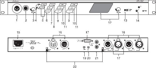
Features
1. DYNAMIC-MIC HEADSET CONNECTOR: Accepts headsets with monaural headphones and either a balanced or unbalanced dynamic microphone.
2. PANEL MIC / ELECTRET-MIC HEADSET CONNECTOR: Accepts an electret gooseneck microphone, such as the Telex Model MCP-90-XX . The model MCP-90 series panel mic connector is a 1/4” stereo plug, with a threaded shaft for easy installation.
3. VOLUME CONTROL: Adjusts headphone volume only.
4. VOX TRIMMERS: Used with the voice-activated microphone feature. Separate trimmers adjust the voice activation level for the headset and panel microphones.
5. HEADSET AND PANEL MIC KEYS: Used to manually activate either the headset or panel microphone, whichever is being used.
6. ALL TALK KEY: Used to talk to all stations that are listening on all channels. This includes both MS-2002 channels and all channels of any connected EMS4001 Expansion Stations.
7. PA KEY: If the MS-2002 is connected to a public address system, this key may be used to talk over the public address system.
8. MIC KILL KEY: Used to turn off the microphones on any intercom stations on a channel. Also used to activate the program inputs and the audible beep feature for incoming calls.
9. INTERCOM TALK KEYS: Momentary or latching (hands-free) operation possible.
4
10.CALL KEYS: Used to place calls on intercom channels and to indicate incoming calls.
11.INTERCOM LISTEN KEYS: Momentary or latching operation possible.
12.SPEAKER VOLUME CONTROL: The Volume control adjusts the level to the front panel speaker. If an external speaker is used, volume must be adjusted at the external speaker.
13.COMBINE / ISOLATE SWITCH:This recessed, pushbutton switch lets you combine the audio signals of the two channels to create a single audio channel where all users can intercommunicate. Or, you can isolate each channel to create two groups of completely independent users. For normal operation, it should be set in the isolate position.
14.CHANNEL STATUS INDICATORS AND RESET PUSHBUTTON:The indicators are green for normal operation and red when there is an overload or short circuit. The Reset pushbutton restores normal operation after the short-circuit or overload has been located and fixed.
15.UNIVERSAL AC POWER INPUT: The MS-2002 accepts any input power in the range of 100-240 VAC, 50/60 Hz.
16.2-CHANNEL INTERCOM CABLE CONNECTORS: One male and one female XLR-6 connector for 2-channel operation with SS2002, BP2002, etc.
17.PROGRAM INPUTS CONNECTOR AND TRIMMERS: Each intercom channel has its own program input and level adjust trimmer. The program inputs may be turned on or off via the front panel and they may be set to interrupt during talk, if desired.
18.1- CHANNEL INTERCOM CABLE CONNECTORS: Two connectors are provided for each channel for loop-through connection of 1-channel intercom stations, such as the SS1002, BP1002, etc.
19.PA OUTPUT: Connects to a public address system.
20.EXPANSION OUT CONNECTOR: Connects to an EMS4001 Expansion Station.
21.SPEAKER OUTPUT JACKS: May be used with external, powered loudspeakers for monaural or binaural listening configurations.
22.BALANCED / UNBALANCED SELECTOR SWITCHES: The selector switches sets the MS-2002 for compatibility with either Audiocom or Clear-Com* channel connector pin-outs, channel power requirements, and call signaling requirements. Both switches must be in the same position.
5
Installation
Unpacking
The package contains the following items. Contact the shipper or your Audiocom dealer immediately if anything is damaged or missing. Detach and fill out the registration card and return it to Telex to properly register your MS-2002.
Qty |
Description |
|
|
1 |
MS-2002 Master Station and Power Station |
1 |
Warranty and Registration Card |
1 |
User Manual |
2 |
Black Face Plates |
|
|
WARNING
The following instructions are for use by qualified personnel only. To avoid electric shock, do not remove the cover unless you are qualified to do so.
AVERTISSEMENT
Les instructions qui suivent s’adressent uniquement a un technicien qualifie. Pour evite des chocs electriques, ne pas ouvrir le boitier, a moins d’y entre habilite.
Configuration Pre-check
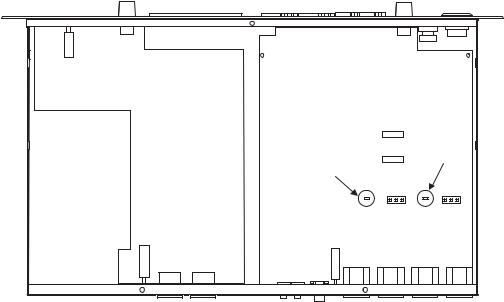
Before connecting the MS-2002 make sure that it is properly configured for your intended usage. Figure 2 shows the locations of the configuration switches. To access internal switches, remove three screws from the top cover and three screws from the bottom portion of each side.
6
|
SW3 |
Channel 2 |
SW1 |
|
|
Sidetone |
|
|
1 2 3 |
R601 J6
Channel 1
Sidetone
1 2 3
R59 J3
Figure 2 - Locations of Configuration Jumpers and Switches
Switch # |
Description |
Settings |
Default |
|
|
|
|
|
|
|
DIP SWITCH SW1 (INTERNAL) |
|
||
SW1-1 |
Headset microphone type |
On: Unbalanced |
Off |
|
Off: Balanced (Typical) |
||||
|
|
|
||
SW1-2 |
Call signal send, channel 1 |
On: Enabled |
On |
|
Off: Disabled |
||||
|
|
|
||
|
|
|
|
|
SW1-3 |
Call signal receive, channel 1 |
On: Enabled |
On |
|
Off: Disabled |
||||
|
|
|
||
|
|
|
|
|
SW1-4 |
Call signal send, channel 2 |
On: Enabled |
On |
|
Off: Disabled |
||||
|
|
|
||
|
|
|
|
|
SW1-5 |
Call signal receive, channel 2 |
On: Enabled |
On |
|
Off: Disabled |
||||
|
|
|
||
|
|
|
|
|
SW1-6 |
Mic kill signal send |
On: Enabled |
Off |
|
Off: Disabled |
||||
|
|
|
||
|
|
|
|
|
SW1-7 |
Program 2 interrupt |
On: Interrupt during talk |
Off |
|
Off: No interrupt |
||||
|
|
|
||
|
|
|
|
|
SW1-8 |
Program 1 interrupt |
On: Interrupt during talk |
Off |
|
Off: No interrupt |
||||
|
|
|
||
|
|
|
|
|
|
BALANCED (BAL) - UNBALANCED (UNBAL) OPERATION |
|
||
|
BOTH SWITCHES MUST BE SET THE SAME. |
|
||
|
FACTORY DEFAULT IS BALANCED. |
|
||
Rear Panel |
Audiocom or Clear-Com |
Out: Balanced (Audiocom) |
Out (BAL) |
|
operation |
In: Unbalanced (Clear-Com) |
|||
|
|
|||
Rear Panel |
Audiocom or Clear-Com |
Out: Balanced (Audiocom) |
Out (BAL) |
|
operation |
In: Unbalanced (Clear-Com) |
|||
|
|
|||
|
|
|
|
|
|
DIP SWITCH SW3 (INTERNAL) |
|
||
|
*SET ALL TO MONAURAL OR ALL TO BINAURAL |
|
||
SW3-1 |
Incoming call beep, headset |
On: Disabled |
Off |
|
Off: Enabled |
||||
|
|
|
||
|
|
|
|
|
SW3-2* |
Listen 1 to speaker 1 only |
On: Enabled (Binaural) |
Off |
|
Off: Disabled (Monaural) |
||||
|
|
|
||
|
|
|
|
|
SW3-3 |
Incoming call beep, speaker 1 |
On: Enabled (SW3-1 must be off) |
Off |
|
Off: Disabled |
||||
|
|
|
|
|
SW3-4 |
Incoming call beep, speaker 2 |
On: Enabled (SW3-1 must be off) |
Off |
|
Off: Disabled |
||||
|
|
|
|
|
SW3-5 |
Listen 2 to right headphone |
On: Enabled (Monaural) |
On |
|
Off: Disabled (Binaural) |
||||
|
|
|
||
|
|
|
|
|
SW3-6 |
Listen 2 to speaker 2 |
On: Enabled (Binaural) |
Off |
|
Off: Disabled (Monaural) |
||||
|
|
|
||
|
|
|
|
|
SW3-7 |
Listen 2 to speaker 1 |
On: Enabled (Monaural) |
On |
|
Off: Disabled (Binaural) |
||||
|
|
|
||
|
|
|
|
|
SW3-8 |
Listen 1 to left headphone |
On: Enabled (Monaural) |
On |
|
Off: Disabled (Binaural) |
||||
|
|
|
||
|
|
|
|
|
Table 1 - Configuration Switch Settings
7
Headset Microphone Type Selection DIP Switch
SW1-1 applies only to a dynamic-mic headset connected to the dynamic-mic headset jack on the front panel. If the headset specifications indicate the microphone type is balanced, or if you are unsure, leave this switch in the off (default) position. If the specifications indicate an unbalanced microphone set SW1-1 to on.
Note: For best results in noisy environments, a noise canceling (directional or cardioid) micro phone is highly recommended. This is especially true if you are using the Vox feature.
Mic Kill Send Enable DIP Switch
The MS-2002 can generate an inaudible signal which will turn off the microphones on all intercom stations on a channel (for stations that detect this signal). This feature is useful, for example, when an unattended microphone has been left on and is causing unnecessary noise on a channel. By default, Mic Kill is not enabled. To activate this feature set SW1-6 to the on position.
Program Interrupt DIP Switches
If you plan on using external program sources with the MS-2002, you have a choice of whether or not you want the program audio to shut off on the intercom channel while you are talking. By default, program audio does not interrupt during talk. You can change this as follows:
1.For channel 1 program interrupt during talk, set SW1-7 to on .
2.For channel 2 program interrupt during talk, set SW1-8 to on .
Incoming Call Beep DIP Switches
If call signal receive is enabled (switches SW1-3 and SW1-5), incoming calls will be indicated by red-flashing Call keys. An optional beep tone can also be used. Internal switches enable the beep tone. You can then turn the beep tone on or off via the front panel during normal operation. Enable the beep tone as follows:
1.Make sure the call signal receive DIP switches are on (SW1-3 and SW1-5).
2.For incoming call beep in a headset, set SW3-1 to off.
3.For incoming call beep in speaker 1, set SW3-1 to off and SW3-3 to on.
4.For incoming call beep in speaker 2, set SW3-1 to off and SW3-4 to on.
5.The procedure to turn incoming call beep on or off during operation can be found on page .
Monaural or Binaural Operation DIP Switches
The MS-2002 can be used with a single speaker or monaural headphones (singleor double-sided) for monaural operation. In this case, all audio signals are combined and sent to the headphones and the front panel speaker. The combined signals also go to the Speaker 1 jack on the back panel. The MS-2002 can also be used with two speakers for binaural operation. In this case, channel 1 is sent to the Speaker 1 jack and channel 2 is sent to the Speaker 2 jack. Binaural headphone operation is not supported.
For monaural operation with headphones or one speaker (factory default):
1.Set SW3-2 to off.
2.Set SW3-5 to on.
3.Set SW3-6 to off.
4.Set SW3-7 to on.
5.Set SW3-8 to on.
8
 Loading...