

Page 1
Telex
Operating Instructions
R
T
elex
Personal Listening Systems
P
ST-170
PST-170
17 Channel
Synthesized Transmitter
R
Page 2

PST-170 SPECIFICATIONS
Number of Channels ·············17User Selectable Channels
Power Output ·············80,000 uV/M at 3 meters, maximum
Antenna ···················Permanently attached trailing wire
Modulation ·······················FM,+/-25KHzDeviation
Frequency Response (System) ············100Hzto10,000 Hz
Audio Input:
Microphone, 7.75 mV RMS input for 25 KHz deviation.
Impedance, 10 K Ohms, nominal.
Aux. Input, 100 mV. Unbalanced, 100K Ohms, nominal.
Audio Input Level ············0-42 dB attenuation in 6 dB steps
Signal to Noise Ratio: ·······················Normal 58 dB
EDR enabled 77 dB
Pre-emphasis ····························115uSeconds
Power ··············2AAAlkaline or Nickel Cadmium batteries
Battery Life ······························8Hrs-Alkaline
4 Hrs - Nickel-cadmium
CHANNEL ASSIGNMENT
Channel # Freq. (MHz) Channel # Freq. (MHz)
A 72.1 J 75.5
B 72.2 K 75.6
C 72.3 L 75.7
D 72.4 M 75.8
E 72.5 N 75.9
F 72.6 0 74.7
G 72.7 P 75.3
H 72.8 Q 75.4
I 72.9
-1-
Page 3
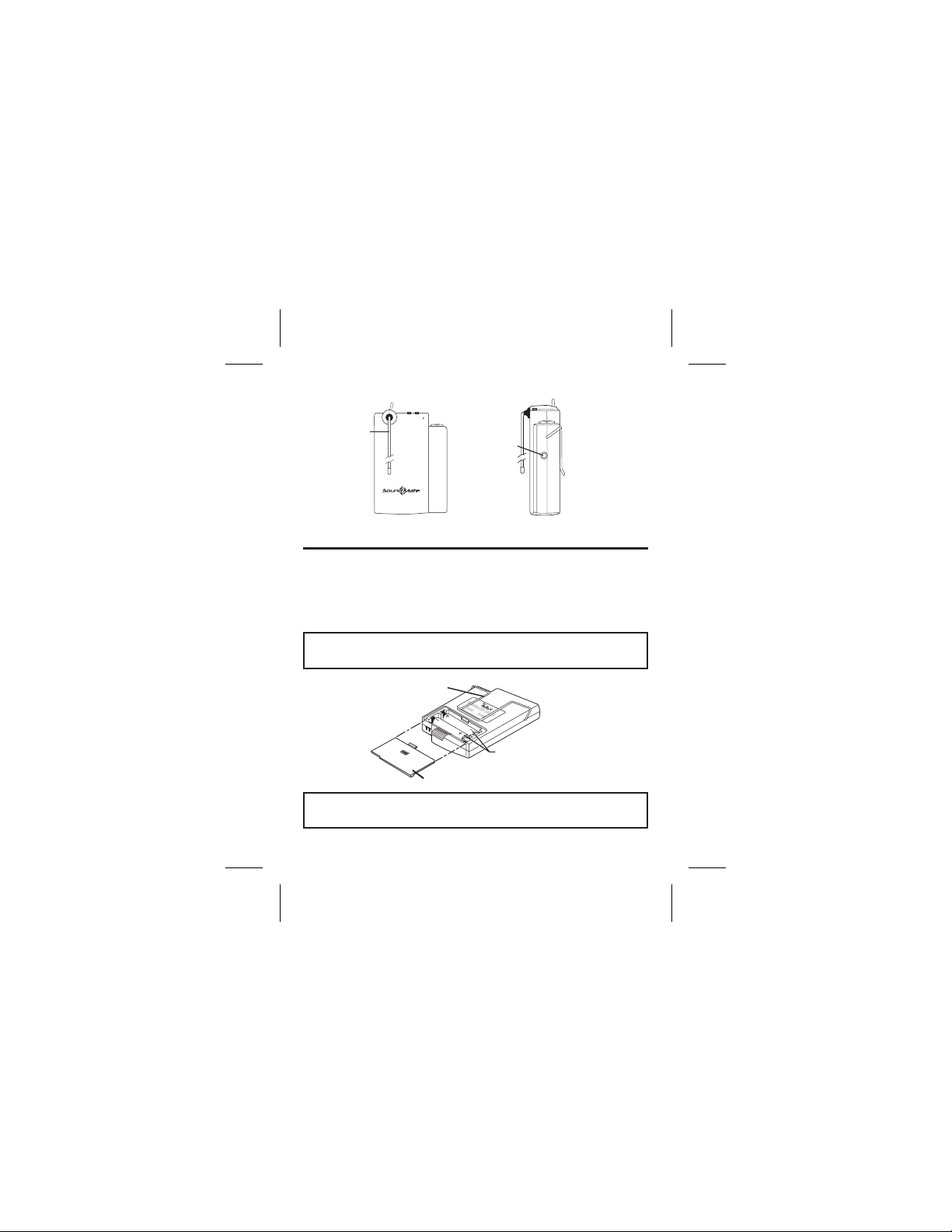
ANTENNA
PersonalListening Systems
P
ST-170
R
T
elex
AUXILLIARY
INPUT JACK
fdffdlf;
BATTERIES
Front View
Side View
The PST-170 Transmitter uses two AA batteries. Position
them in the battery compartment as illustrated. You can expect 8 hours of operation from alkaline batteries and 4 hours
on nickel-cadmium batteries. Charge Pins are provided on
the bottom of the unit that fit Telex drop in chargers.
CAUTION: Do not attempt to recharge alkaline batteries as this
may result in personal injury.
BELT CLIP
BELT CLIPBELT CLIPBELT CLIP
BATTERY
ORIENTATION
BATTERY COMPARTMENT COVER
NOTE: If the unit is to be stored for any length of time be sure to
remove the batteries from the unit.
-2-
Page 4

Transmitter Channel
The PST-170 Transmitter may be set to any one of 17 channels.
Two Transmitters cannot operate on the same channel un
less separated by 300 feet (91 m) or more (which is the aver
age maximum operating range). If two transmitters are
operating on the same channel inside this perimeter, the re
ceivers will pick up the FM signal of both transmitters, caus
ing a squealing sound to be heard.
Antenna
The transmitter uses a flexible wire “trailing” antenna that is
permanently attached to comply with FCC Part 15 Rules. Do
not cut or lengthen the antenna. Do not coil the antenna and
place in your pocket. This is a tuned antenna and modification will shorten the range.
Audio Input
There are 2 audio input jacks on the transmitter. One is the
Auxiliary
teachers aids or tape players to be used. The input jack is a
1/8 inch (3.5mm) stereo/mono jack. Typical input level is 100
mV RMS maximum for normal modulation. More than this in
put will cause the audio to “limit” which may sound unnatural.
Reduce the input level, if this should happen, by turning
down the input device.
input designed to allow audio devices such as
-3-
-
-
-
-
-
Page 5

The second jack is the microphone input. This jack is located
on the top panel “step” of the transmitter. The microphone is
supplied with the transmitter but other types can be used as well.
SWITCH
BUTTON
MICROPHONE
JACK
SET
SET
BUTTON
-dB
E.D.R.
Top View
SWITCH
OFF
POWER
SWITCH
ANTENNA
Frequency/Channel Considerations
As with any radio device, interference can occur at any time.
The frequencies offered are shared with other legitimate us
ers. Check the frequency/channel with a receiver to see if
any interference is present. If interference is present, choose
a different channel. The severity of interference varies with
location and distance to the interfering station. If the interfer
ence is weak on all channels, this is probably acceptable
since the PST-170 will cover the interference and is unlikely
to interfere with other users. Multiple Channel Systems re
quire other considerations but each channel should be
checked as above.
-4-
-
-
-
Page 6

Placement of the Transmitter and Microphone
Place the transmitter on the users belt or in their pocket,
preferably with the antenna facing the receiver. Do not
the antenna and put it in a pocket. This will severely reduce
the operating range.
Place the microphone about 10 to 12 inches below the mouth
of the user.
Transmitter Operation
Turn on the transmitter with the toggle switch on top of the
PST-170.
LCD Display
1. Channel Display A through Q, low battery indicator and input level
2. Lock Indicator (see Change Lock Out)
3. Overmodulation indicator (when symbol is showing)
4. Enhanced Dynamic Range Indicator
5. Input level adjustment indicator
2
1
5
coil
-dB
E.D.R.
E.D.R.
LCD Display
-5-
3
4
Page 7

Channel Selection and Input Adjustment
1. Turn the receiver on and plug a microphone into the mic jack.
A channel letter will show in the display.
2. Press the set button once and the Channel indicator will flash.
3. Press the button and the Channel will cycle up. Match the
channel to the receivers being used (SR-50, SR-100, SR-400
or check frequency chart to match other brands).
4. Press SET, the channel indicator will stop flashing and the in
put level will be displayed and flash.
5. Speak into the microphone while watching the display. The
symbol will be displayed when the input is overmodulating
(too strong). Push the ARROW button to adjust the input level
until the symbol shows just on the loudest speech.
6. When the input is adjusted, press SET and the display will
stop flashing and the channel will be displayed.
7. If the lights up during operations, it is indicating
overmodulation. Re-adjust the input level.
If the microphone and an auxiliary device is used at the
same time, it is preferable to set the auxiliary input device
with its own control.
Adjust the appropriate output level control until loud program
material passages sound natural in the receiver. This allows
sufficient "head room" to prevent peak distortion on loud in
puts.
-6-
-
-
Page 8

Enhanced Dynamic Range (E.D.R.) Operation
The Telex PST-170 Transmitter is equipped with E.D.R., En
hanced Dynamic Range (companded) audio. This mode
greatly improves the Audio Signal to Noise Ratio when used
with the Telex Model SR-400 receiver. The E.D.R. mode must
be selected on both the transmitter and receiver to be effec
tive.
1. To engage the E.D.R. function turn the PST-170 off with the
toggle switch.
2. Press and hold the SET button while you turn the PST-170
back on. The E.D.R symbol will be display in the lower right
corner to indicate the mode is active.
3. Repeat the procedure to turn off the E.D.R. function.
Change Lock Out
The PST-170 SET button can be locked to prevent E.D.R.
activation, and unintended channel changes.
1. To engage the Lock Out Feature, press the SET and ARROW
buttons at the same time and hold them down for 10 seconds.
2. The padlock symbol will appear and the set button is disabled.
3. To unlock the system, press the SET and ARROW buttons
and hold them for 10 seconds or until the padlock symbol dis
appears.
-7-
-
-
-
Page 9

Low Battery Indication
1. When there is approximately 10% of the battery life left, a bat
tery symbol will flash alternately with the Channel letter in the
LCD display.
2. When there is only 5% battery life left, the battery symbol will
constantly flash in the display.
System Walk Through
Now that the transmitter is set up, you should be able to hear
the program material on the receiver. Walk the receiver
through the area that it is intended to be used in. Check for
any noise or interference that would cause undesired operation. Some of the causes of poor performance are listed below.
.
Transmitter antenna coiled up
.
Poor transmitter location
.
Poor receiver location
.
Interference
.
Local AC Line noise
.
RF “Trouble Spots”
.
Operating distance beyond system capability
.
Malfunctioning System, receiver or transmitter
-8-
-
Page 10

FCC INFORMATION
The Telex Model PST-170 is authorized under FCC Rules
Part 15. Licensing of Telex equipment is the user’s responsi
bility and licensablilty depends upon the user’s classification,
and frequency selected.
CAUTION: Changes or modification made by the user could void
the user’s authority to operate the equipment.
Operation is subject to the following two conditions: (1) This
device may not cause interference, and (2) this device must
accept any interference, including interference that may
cause undesired operation of the device.
ACCESSORIES
Description Catalog No.
OLM-10 microphone (supplied with PST-170) .......... OLM10
ELM-22 Micro Mini lapel microphone .............. 70925-001
RE92Tx Unidirectional lapel microphone ...........301456000
SCHS-745 headworn microphone ...................745TA4
BC-100 battery charger-2 pocket .................71216-000
(also fits SR-50/400 receivers)
Waist Belt ..................................17794-002
Cell Phone style belt clip ........................879518-1
-9-
-
Page 11

WARRANTY INFORMATION
Model(s)_________________________ Serial No(s).:_____________________
Date of Purchase __________________________________________________
Purchased From __________________________________________________
Address _________________________________________________________
City _______________________ State______________ Zip _______________
TELEX Communications, Inc. (“Telex”)warrants to the user, who originally pur
chased the serialized product delivered with this card, that the product will be
free from defects in material and workmanship for the following periods after
such date of purchase. Material 36 months, workmanship 36 months. Micro
phones, earphones, neckloops, cables & connectors are warranted for ninety
days. Telex will, at its option, repair or replace free of charge such defective
products subject to the following conditions:
1. Delivery of the product or parts postage prepaid to the Telex dealer, authorized ser-
vice facility or factory.
2. Determination by Telex that a defect exists and is covered by limited warranty. De-
fects due to alteration, repair by unauthorized persons, insertion of non-Telex parts,
misuse, accidental damage, use of the equipment for purposes other than those for
which it was designed, and the like, are not covered by this limited warranty and repairs thereof will be subject to normal service charges.
3. Repairs and replacement parts are covered under this limited warranty only for the
unexpired term of the original limited warranty.
4. Products purchased from unauthorized dealers are not warranted.
5. You must fill out and return the product warranty card to register the purchase date
of serialized items. A copy of the bill of sale showing the date of purchase must ac
company all warranty work.
THIS LIMITED WARRANTY IS EXPRESSLY IN LIEU OF ANY EXPRESS OR IMPLIED
WARRANTY, INCLUDING ANY IMPLIED WARRANTY OR MERCHANTABILITY OR FIT
NESS FOR A PARTICULAR PURPOSE WHICH EXTENDS BEYOND THE T ERM
HEREOF. THE REMEDIES PROVIDED BY THIS LIMITED WARRANTY ARE THE ONLY
REMEDIES AVAILABLE TO ANY PERSON. NO PERSON HAS ANY AUTHORITY TO
BIND TELEX TO ANY REPRESENTATION OR WARRANTY OT HER THAN THOSE
PROVIDED BY THIS LIMITED WARRANTY. TELEX SHALL NOT BE LIABLE FOR ANY
INCIDENTAL OR CONSEQUENTIAL DAMAGES CAUSED BY FAILURE OR OTHER
WISE OF THE PRODUCT.
Some states do not allow exclusions or limitations of incidental or consequential damages
or limitations on how long an implied warranty lasts, so the lim itations or exclusions
herein may not apply to you. This warranty gives you specific legal rights, and you may
also have other rights which vary from state to state.
FILL OUT AND RETAIN THIS PORTION FOR YOUR RECORDS
LIMITED WARRANTY (VALID UNITED STATES AND CANADA ONLY)
-
-
-
-
-
Page 12

Detach Warranty Registration and mail to:
Telex Communications, Inc.
12000 Portland Ave. South,
Burnsville, MN 55337
"
WARRANTY REGISTRATION
Limited Warranty (Previous Page)
SOUND ENHANCEMENT SYSTEMS
Owner’s Name___________________________________________________________
Address_________________________________________________________________
City_____________________________ State__________________Zip_____________
Purchased From__________________________________________________________
Address_________________________________________________________________
City_____________________________ State__________________Zip_____________
Date of Purchase_________________________________________________________
Model No(s).:_____________________________ Serial No(s).:___________________
Page 13

R
TELEX COMMUNICATIONS, INC. 12000 Portland Ave.South, Burnsville, MN 55337
PN 38110370 June 2004 Made in U.S.A.
 Loading...