

Page 1
AUDIOCOM " INTERCOM SYSTEMS
MODEL
PS-1
FLUSH-MOUNT
POWER SUPPLY
INSTALLATION AND OPERATION INSTRUCTIONS
GENERAL DESCRIPTION
The Telex AudiocomT" Model PS-1 F Power Supply
mounts in a standard two-gang electrical outlet box. VOLTAGE AND LOW VOLTAGE WIRING IN THE
It may be used to power a single intercom channel SAME OUTLET BOX. ANY INSTALLATION OF
containing up to 25 belt-pack headset stations. It
may also be used as a local power source for NATIONAL AND LOCAL ELECTRICAL CODES.
speaker stations such as the Telex Model ICQSF.
THE PS-IF REQUIRES CONNECTION OF LINE
THIS UNIT MUST MEET ALL RELEVANT
WARNING
INSTALLATION
1. Ac power should be supplied from a circuit
SPECIFICATIONS
Power Requirements: 105-1 25 Vac, 50-60 Hz,
30 watts
Output Voltage: 24 Vdc regulated (less than
50 millivolts ripple)
Output Current:
-
500 milliamps maximum continuous
-
700 milliamps maximum intermittent
-
240 milliamps short circuit current limiting
Channel Terminating Impedance (provided
PS-1
F):
300 ohms t15O/0
Connectors:
-
Intercom Channel: Three screw terminals with
wire clamps for No. 14-22 AWG stranded or solid
wire
-
Power: Three wire pigtails
by
protected by a service fuse or circuit breaker
with a maximum rating of 15 amps. Connect ac
power to the black and white leadwires; connect
ground to the green wire.
2. To power an intercom channel: Connect the
intercom channel to the CHANNEL terminals,
and connect intercom dc return to the SHLD
terminal.
To locally power a speaker station: Connect the
speaker station positive terminal to either one of
the PS-1 F CHANNEL terminals, and connect
F
speaker station ground to the PS-1
terminal. The remaining CHANNEL terminal on
the PS-IF is not used. On the speaker station,
be sure to remove the jumper installed between
the +24 and PH terminals. (This jumper is used
only when the speaker station is phantom
powered from the intercom channel.)
3.
Mount the PS-IF in an electrical box using the
screws provided with the unit.
-.
SHLD
TELEX
J
Model
PS-IF
Dimensional Drawing
TELEX.
COMMUNICATIONS, INC. 9600 Aldrich Ave. So., Minneapolis, MN
55420
1
I
U.S.A.
Page 2
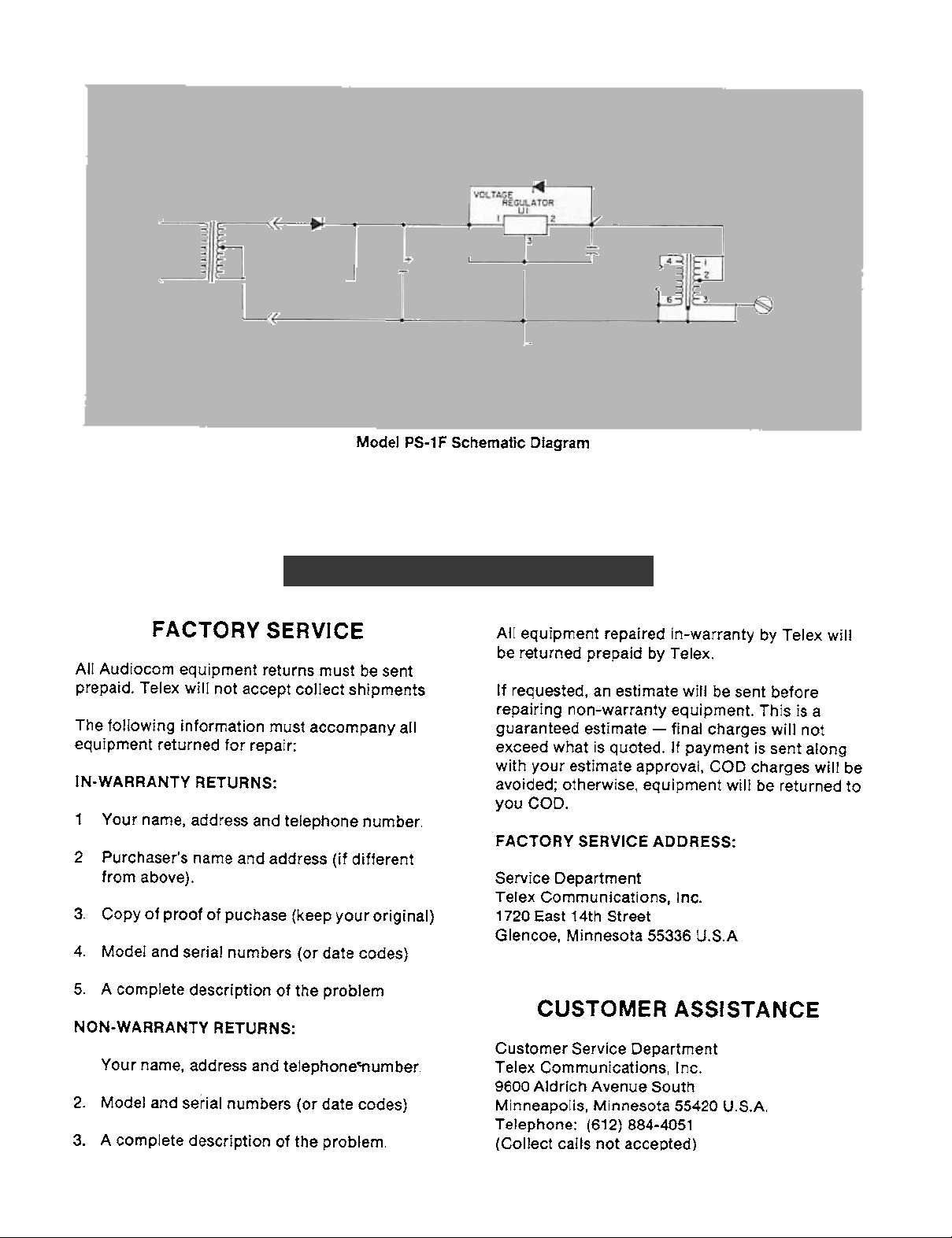
CR3
.ISUF
,
CHASSIS CONNECTION
Model PS-1F Schematic Diagram
SERVICE INFORMATION
CHANNEL
FACTORY SERVICE
All Audiocom equipment returns must be sent
prepaid. Telex will not accept collect shipments.
The following information must accompany all
equipment returned for repair:
IN-WARRANTY RETURNS:
1
Your name, address and telephone number.
2. Purchaser's name and address (if different
from above).
3. Copy of proof of puchase (keep your original)
4. Model and serial numbers (or date codes)
5. A complete description of the problem.
NON-WARRANTY RETURNS:
Your name, address and telephonernumber.
2. Model and serial numbers (or date codes)
3. A complete description of the problem.
All equipment repaired in-warranty by Telex will
be returned prepaid by Telex.
If requested, an estimate will be sent before
repairing non-warranty equipment. This is a
guaranteed estimate -final charges will not
exceed what is quoted. If payment is sent along
with your estimate approval, COD charges will be
avoided; otherwise, equipment will be returned to
you COD.
FACTORY SERVICE ADDRESS:
Service Department
Telex Communications, Inc.
1720 East 14th Street
Glencoe, Minnesota 55336 U.S.A.
CUSTOMER ASSISTANCE
Customer Service Department
Telex Communications, Inc.
9600 Aldrich Avenue South
Minneapolis, Minnesota 55420 U.S.A.
Telephone: (61 2) 884-4051
(Collect calls not accepted)
 Loading...