

Page 1
PROCOM
2
AIRCRAFT INTERCOM
USER INSTRUCTIONS
INSTALLATION
(Refer to the System Configuration drawing)
Plug the ProCom 2 (PC 2) into the aircraft radio or audio panel jacks.
NOTE: If the aircraft radio does not provide sidetone, the pilot will not be able to hear himself or herself
in the headset during aircraft-to-tower transmissions.
Plug pilot and copilot (or passenger) headphone and microphone plugs into the appropriate jacks on the top panel
of the PC 2.
Push To Talk
1. If the aircraft has a built-in pilot yoke switch, it is not necessary to use the pilot PTT jack on the PC
However,
keying the transmitter with the built-in yoke switch will also ground the jack tip. This signal is then
sensed by the PC
during transmission.
2. If the aircraft has a built-in copilot yoke switch, it should not
desired, use a portable PTT switch plugged into the copilot PTT switch jack on the PC 2.
3. If poltable
to
be
Connect an extemal msic source to the rear panel MUSIC INPUT jack of the PC 2 using a 0.140-inch (3.6 mm)
stereo "miniplug."
Use one of two methods to provide power to the PC 2 intercom:
For internal power operation, install a 9-~0lt battery in the side compartment of the PC 2.
For external power operation, use an optional aircraft cigarette lighter cable (Telex Catalog Number 96513-
000). It is recommended that you use a 100 mA (fast blo) fuse in the external power source. Plug the cable
into the aircraft cigarette lighter and into the AUX POWER jack on the rear panel of the PC 2.
it
is important that the aircraft radio or audio panel microphone jack tip
2
(via the Ytable microphone/PTTplug) to cause proper operation of the intercom
PTT
switches are used,
pressed to talk over the intercom. Plug microphones into the PC 2 microphone jacks only.
do
(PlT)
Swltch Notes
be
wired so that
be
used. lf copilot PTT capability is
not plug microphones into them, as the PTT switches will have
CAUTION
2.
O
Copyright
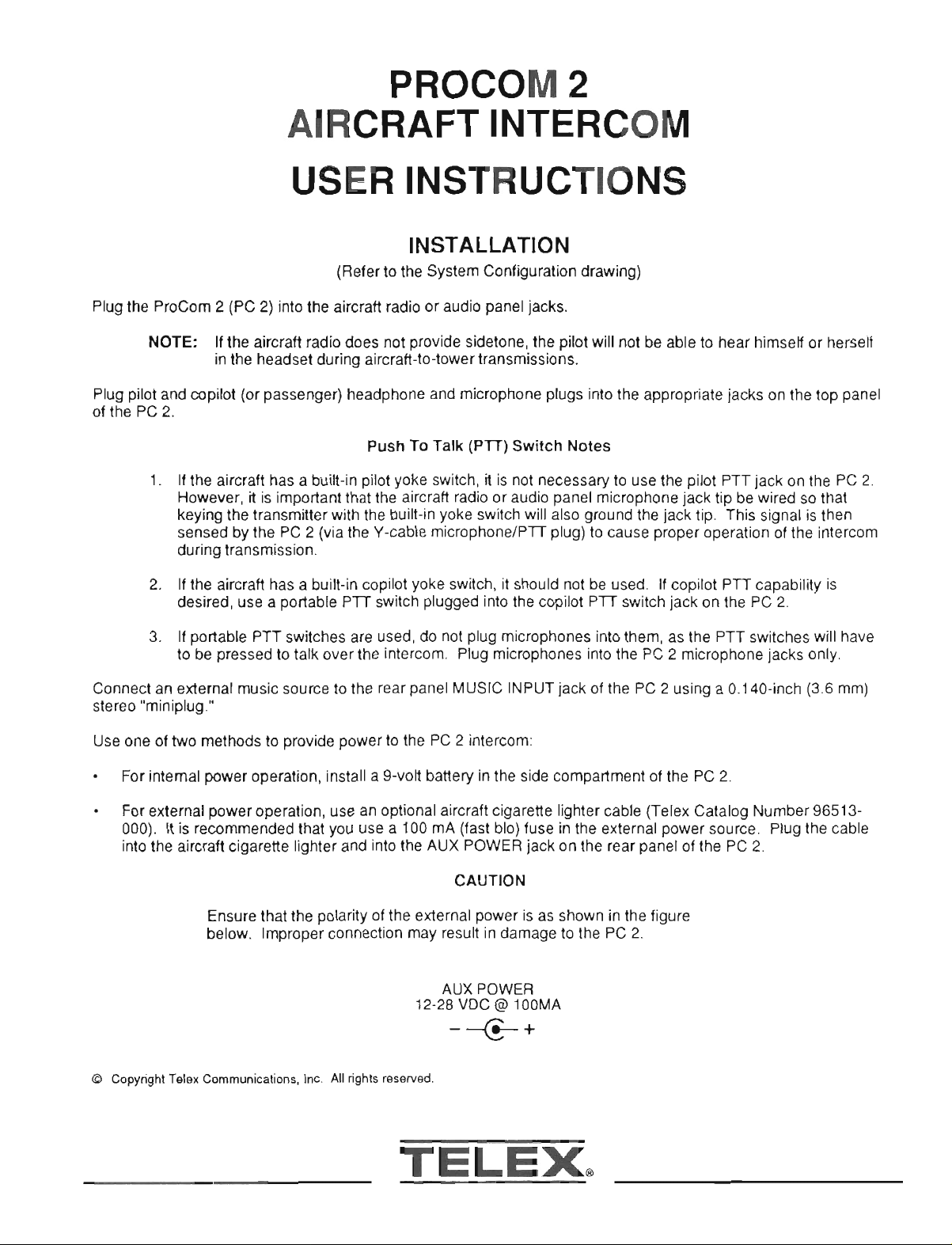
Ensure that the polarity of the external power is as shown in the figure
below. lrrpmper connection may result in damage to the PC 2.
AUX POWER
Telex
Communicalions.
Inc.
All
tights
12-28 VDC
resewed.
@
100MA
TELEX,
Page 2
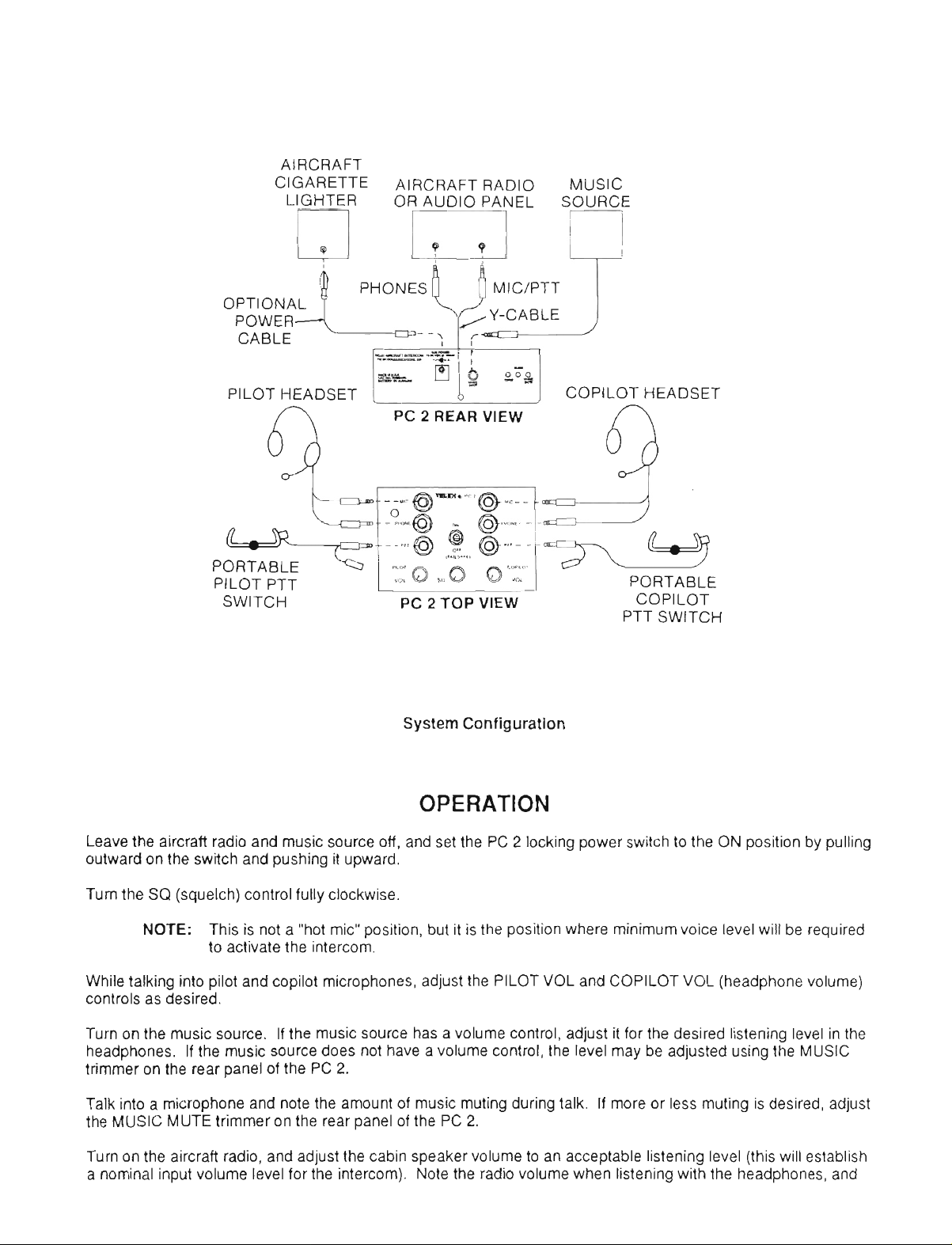
AIRCRAFT
CIGARETTE AIRCRAFT RADIO MUSIC
LIGHTER OR AUDIO PANEL SOURCE
n
m
n
opTloNA$
POWER Y-CABLE
CABLE
PILOT HEADSET COPILOT HEADSET
/-7
PHOY
,
--$/
%%-*
nnra
PC
Q
2
REAR
ry
-,
4
go&
VIEW
n
u
PORTABLE
PILOT PTT
SWITCH
PC
2
TOP VIEW COPILOT
System Configuration
PORTABLE
PTT SWITCH
OPERATION
Leave the aircraft radio and music source off, and set the PC 2 locking power switch to the ON position by pulling
outward on the switch and pushing
Tum the SQ (squelch) control fully clockwise.
NOTE: This is not a "hot mic" position, but it is the position where minimum voice level will be required
to activate the intercom.
While talking into pilot and copilot microphones, adjust the PILOT VOL and COPILOT VOL (headphone volume)
controls as desired.
Tum on the music source. If the music source has a volume control, adjust it for the desired listening level in the
headohones. If the music source does not have a volume control. the level mav be adiusted usina the MUSIC
trimnier on the rear panel of the PC
Talk into a microphone and note the amount of music muting during talk. If more or less muting is desired, adjust
the MUSIC MUTE trimmer on the rear panel of the PC
Turn on the aircraft radio, and adjust the cabin speaker volume to an acceptable listening level (this will establish
a nominal input volume level for the intercom). Note the radio volume when listening with the headphones, and
it
upward.
2.
2.
Page 3

compare
difference in levels, adjust the equalization trimmer (labeled RADIO) on the
rear panel of the PC 2 until the radii level is the same as the intercom level.
Set the power switch to OFF (FAILSAFE) when the intercom is not in use to
consewe battery power. In th'is position the pilot phones are connected
directly to the radio (the pilot microphone signal is always connected to the
radio except when copilot is transmitting).
it
to the volume level when talking on the intercom. If there is a
AUTOMATIC SQUELCH OPERATION
The PC 2 contains an automatic squelch circuit which makes most manual
squelch adjustments unnecessary. This circuit uses a built-in microphone
to monitor the noise level in the aircraft. The microohone is located on the
top panel of the PC 2 next to the pilot MIC and
operation, do not obstruct the microphone.
In most cases the manual squelch control should be left in the extreme
clockwise ~osition. and the automatic sauelch circuit will comoensate for
most chan'ges in ambient noise level; hdwever, if the ambieninoise level
during operation of the aircraft becomes too loud and causes undesirable
intercom activation, rotate the squelch control slightly counterclockwise until
the intercom audio tums off. The intercom should reactivate when speaking
into either microphone.
PHONE
jacks. For proper
Rear Panel Trimmer Controls
Squelch Circuit
Microphone
Optional Aircraft Power Cable
2-Foot (0.6 m), with Cigarette Lighter Plug
Model PT-300 Push-To-Talk Switch
...............................
ACCESSORY INFORMATION
..........................
Catalog No. 96513-000
Catalog No. 63966-000
 Loading...