

Page 1
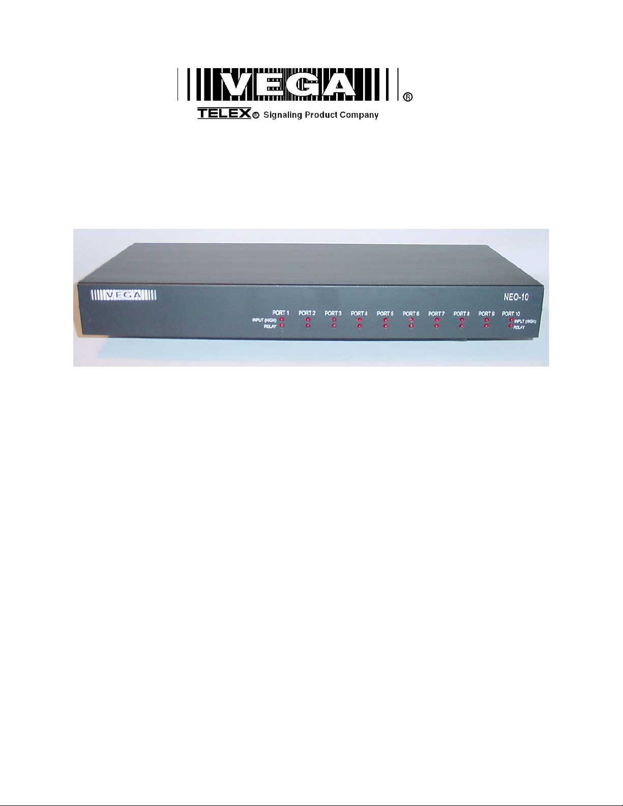
Model NEO-10
Version 1.0
Technical Manual
November 26, 2003 PN: 803968
Page 2

2
Table of Contents
1 INTRODUCTION..............................................................................................................................................3
2 CONNECTING NEO TO THE WORLD........................................................................................................ 4
2.1 RS-232 PORT ...................................................................................................................................................4
2.2 ETHERNET PORT .............................................................................................................................................. 4
2.3 RELAY/INPUT PORTS........................................................................................................................................4
3 SOFTWARE CONFIGURATION OF NEO...................................................................................................5
3.1 SETTING THE BASIC IP INFORMATION WITH HYPERTERMINAL .........................................................................5
3.2 GENERAL SETUP VIA WEB PAGES ....................................................................................................................8
3.3 BASIC ETHERNET SETUP SCREEN..................................................................................................................... 8
3.3.1 Use DHCP Server .............................................................................................................................8
3.3.2 Unit IP Address.................................................................................................................................8
3.3.3 Subnet Mask......................................................................................................................................8
3.3.4 Gateway Address ..............................................................................................................................8
3.3.5 DNS Addresses 1-3 ...........................................................................................................................8
3.4 MULTICAST SETUP.........................................................................................................................................10
3.5 DEBOUNCE INPUT SETTINGS ..........................................................................................................................11
3.6 ECHO PACKET ................................................................................................................................................12
3.7 CLONE FROM OTHER NEO ............................................................................................................................14
3.8 PIN CHANGE..................................................................................................................................................15
3.9 SAVE CHANGES TO EEPROM........................................................................................................................ 16
4 BILL OF MATERIAL AND SCHEMATICS ..............................................................................................17
WARRANTY, SERVICE, REPAIR, AND COMMENTS ..........................................................................18
5
Page 3

3
1 Introduction
The NEO-10 device is a network based Input Output device. Within its enclosure are 10 DPDT relays with all 6
contacts of the relays brought out to ports (Normally Open, Normally Close, Common for each half of relay). There
are also 10 diode blocked inputs which can be used to monitor external events. The NEO sends out multicast packet
bursts anytime a relay or input changes allowing for all users of the device to see status updates in real time. Actual
control of the NEO is accomplished by a TCP/IP socket connection from the controlling console. Version 2.52 of
C-Soft supports control and monitoring functions to support multiple NEO devices on the network. Later releases of
software for the desktop VoIP capable consoles will support NEO as well.
In addition to the I/O functions of the device, NEO supports 10 channels of echo packet functionality. Echo Packet
is a method of copying voice/data content on the network from and to multicast addresses. This features allows the
Vega multicast scheme to operate on a network without having multicast enabled. Until the release of NEO, only
the Vega C-Soft product has this capability which relied on the stability of the Windows operating system. With the
release of NEO this capability is now embedded in dedicated hardware and software in a more robust package.
Page 4
4
2 Connecting NEO to the World
NEO has a total of three different ports that are used to connect it to the world. Likely, the first port that will need to
be connected is the RS-232 port.
2.1 RS-232 Port
The RS-232 port is used for initial setup purposes only. It is a standard DCE pinout allowing a straight through DB9
cable to connect it to a computer or other terminal device for setup. Default baud rate is 19200,N81.
2.2 Ethernet Port
The Ethernet Port is used for setup of the NEO as well as for its operation from the consoles. Control of its relays is
handled through this port. The NEO sends multicast packets whenever status of one of its relays or inputs changes
allow for all users of the device to see real time changes in parallel. The port supports both 10 and 100 Mbps
operation of standard Cat 5 cable.
2.3 Relay/Input Ports
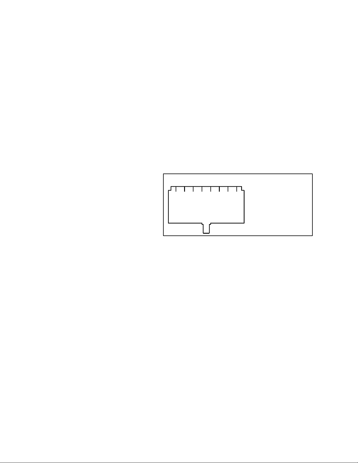
There are 10 RJ45 ports that are used to sense inputs and control external events. Each connector is connected to a
DPDT relay. Both sets of poles are brought out
to the connector allowing for two separate
circuits to be controlled by a single relay. Figure
1 shows the pin out of the rear RJ45s. “Relay1”
designates the pins on one half of the DPDT
relay and “Relay2” the other half. The relays are
rated for 1 Amp at 125VAC. The GND signal is
the signal ground of the device. The INPUT pin
is a diode blocked input that allows sensing of a
1 2 3 4 5 6 7 8 1) Relay1 N/O
2) Relay1 Common
3) Relay1 N/C
4) GND
5) INPUT
6) Relay2 N/C
7) Relay2 Common
8) Relay2 N/O
Connector View
logic signal. The input range is 0-18 volts.
Exceeding the limits of either the Input or the
Figure 1-NEO RJ-45 Connector Pinout
Relays is a violation of the warranty. The
manuals of the various Vega VoIP consoles should be consulted for programming the user interface buttons to
control the relays and sense the inputs of the NEO-10.
Page 5
5
3 Software Configuration of NEO
Setup of the NEO is almost entirely done using a web browser. The first step required during setup is to assign the
IP and Mask addresses to the NEO, using either a WEB Browser or Hyper Terminal program if the assigned IP
address is not accessible on your network.
3.1 Setting the basic IP information with Hyperterminal
As was mentioned before, all other parameters are setup by using a browser such as Netscape or Internet Explorer.
Before connecting to the adaptor with the browser, an IP address and Mask that is compatible with the users existing
network must be set. See your network administrator to determine the proper values. Once these values have been
set, the unit must be reset for them to take affect.
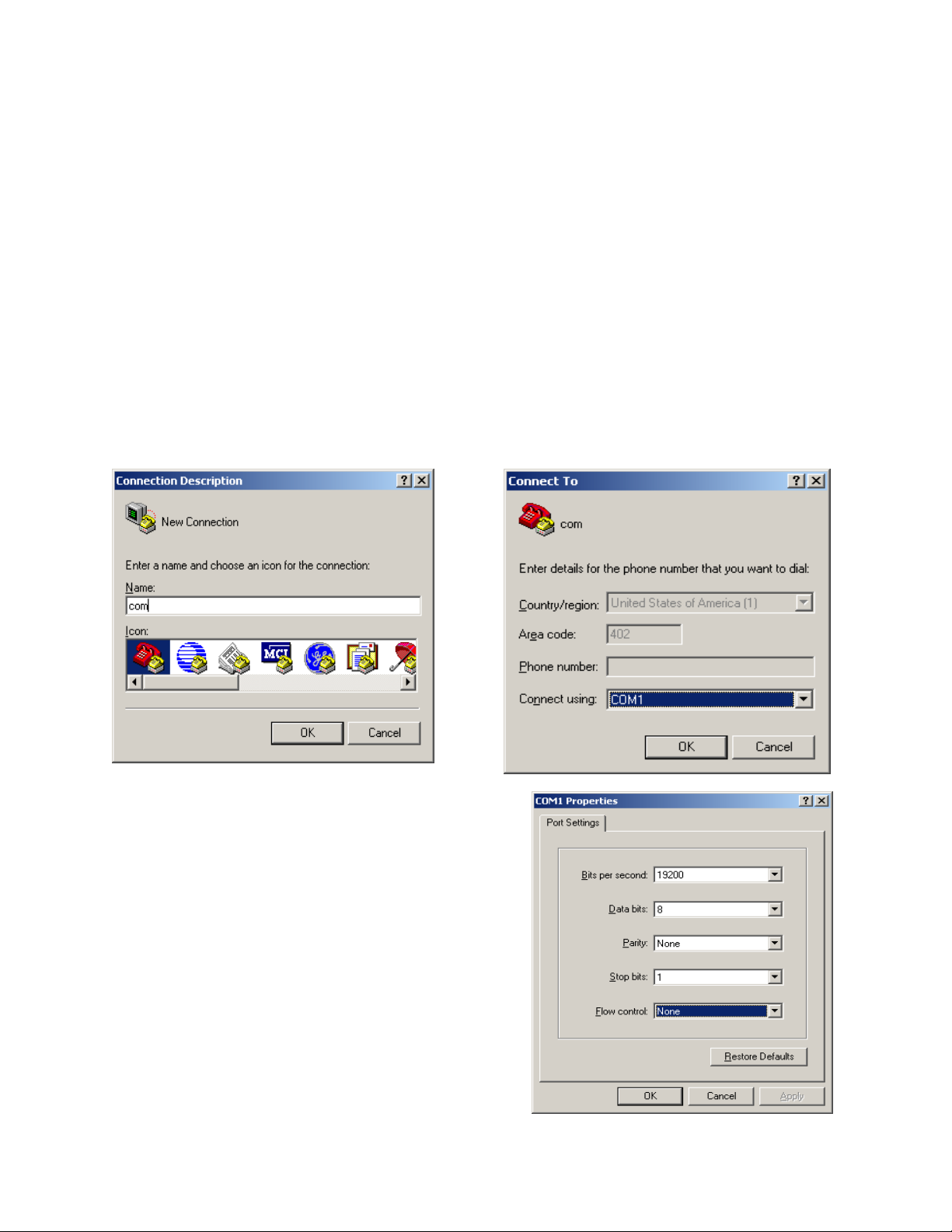
To change the IP and Mask addresses using a Hyper Terminal program follow these simple steps;
Connect the NEO serial port to your computer using a DB9 Serial cable.
Load Hyper Terminal in your PC setting the name to COM.
Set Connect using COM1 or Serial port with cable attached.
Set Baud to 19200 and Flow control to None.
Page 6
6
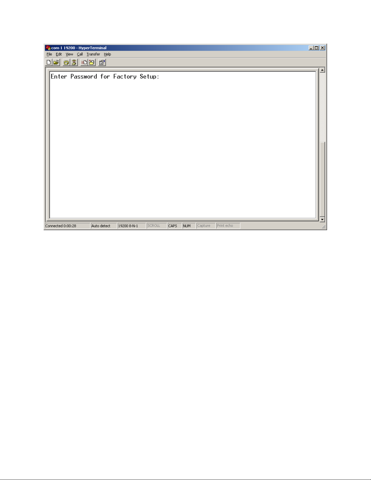
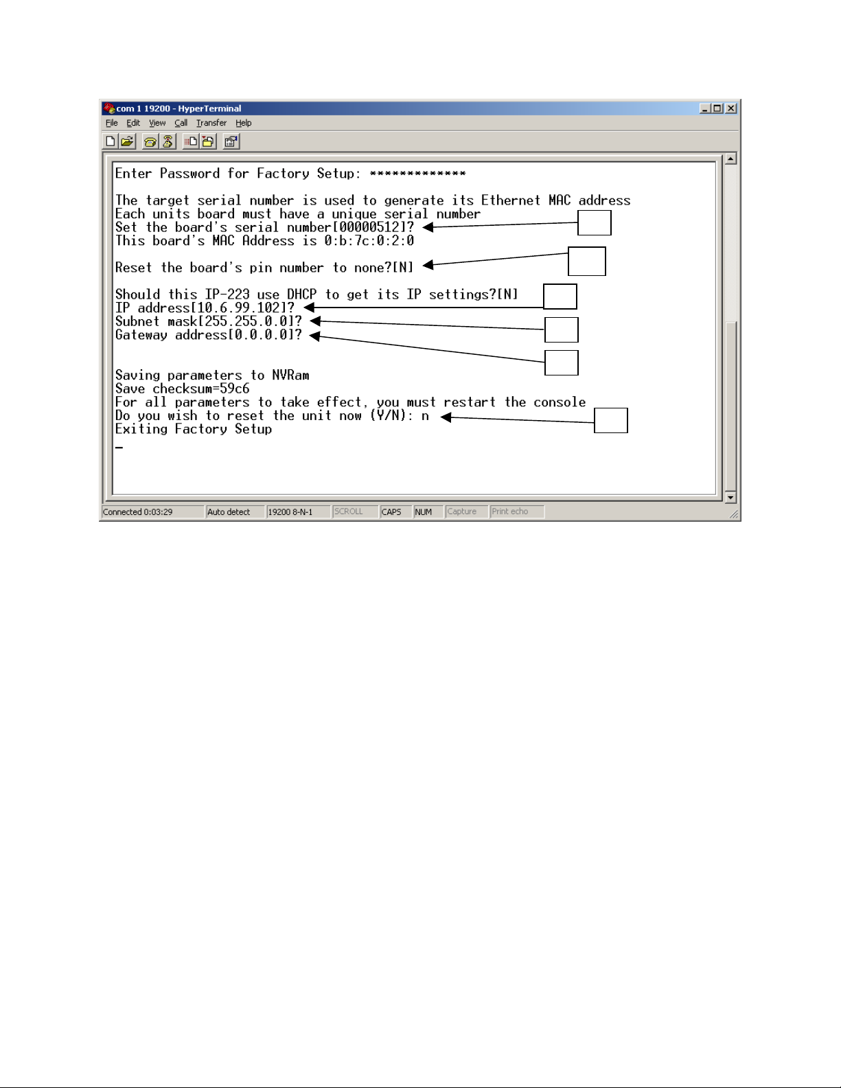
At the main Hyper Terminal screen type uppercase S then <enter>.
Enter “technobabble” for the factory password.
Page 7
7
A
B
C
D
E
F
A = The board serial number and case serial number should match.
B = Do you want to reset the PIN number programmed into NEO.
C = Current IP address, do you want to change?
D = Current Subnet Mask, do you want to change?
E = Current Gateway address, do you want to change?
F = Do you want to reset any of the above?
Once all parameters have been entered and saved, allow the unit to reset by answering Yes to the final question. The
unit will reset in 10-20 seconds. Startup text will be sent to the serial port allowing verification of the setup
parameters having been recorded correctly.
Page 8
8
F
3.2 General Setup via Web Pages
The majority of the setup of the NEO is completed through the Ethernet port. Once the steps of 3.1 have been
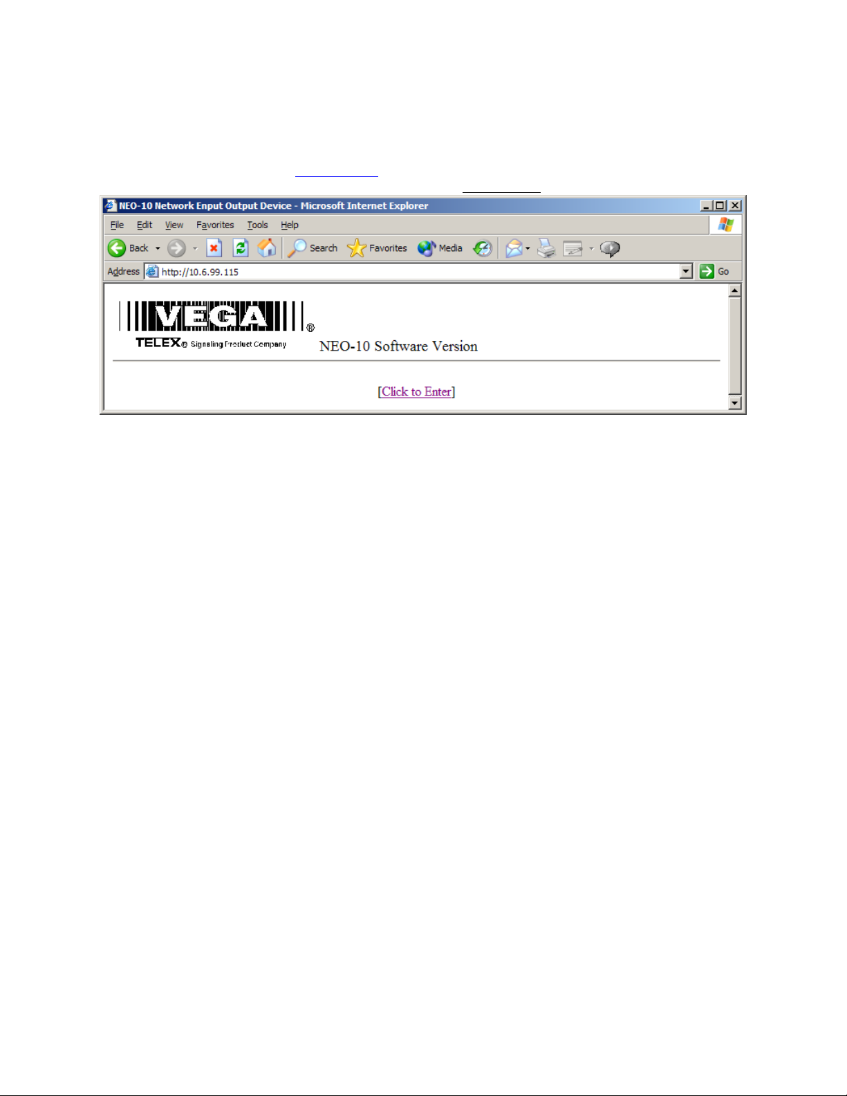
completed, a PC on the network can be used to gain access to the web page based setup of the NEO. In the URL
window of Internet Explorer, type http://X.X.X.X
opening page will appear as shown in Figure 2. Clicking on the [Click to Enter
igure 2-Opening Screen for web page setup
page shown in Figure 3.
where X.X.X.X is the IP address set in the previous section. An
] hyperlink will open the Basic Setup
3.3 Basic Ethernet Setup Screen
The parameters that can be set on the Basic Ethernet Setup Screen are as follows:
3.3.1 Use DHCP Server
This option, when checked will force the NEO to request a dynamic IP address when it is first turned on. Since it is
important that the NEO always be located in a known location for all consoles utilizing it on the network, this should
not be used as the normal operating mode. It is useful sometimes to determine the settings that might be used for a
particular network or testing.
3.3.2 Unit IP Address
In addition to the method outlined in section 3.1, the base IP address can be changed from this screen.
3.3.3 Subnet Mask
Enter the subnet mask into this field. Obtain this information from your network administrator.
3.3.4 Gateway Address
The Gateway Address is the address to which packets are sent when the destination address of the packet is not on
the same subnet as the NEO itself. Obtain this information from your network administrator.
3.3.5 DNS Addresses 1-3
Enter the DNS addresses provided by your network administrator. These are optional and not currently used.
Page 9

9
Once all parameters are set, press the Submit button to send them back to the NEO from the web browser. The
parameters are not updated until they are actually saved to EPROM, (Section 3.9)
Figure 3 – Basic Ethernet Setup Screen
Page 10

10
F
3.4 Multicast Setup
A single multicast address is employed by NEO for the purpose of updating consoles of changes in the Relays and
Inputs.
igure 4 - Multicast Port Number Setup
NEO sends out a single packet each time either a Relay is changed by any console or when an input changes due to
external event. The Multicast Address is any address in the range of 224.0.0.0 to 239.255.255.254. A specific
unicast address can also be used if only a single console is to be utilized. The Port number is a unique port to which
the multicast packet will be sent. Channel Hops is the number of routers that the packet will penetrate before being
stopped and allowed to propagate no further.
The Multicast Address and Port Number must match those set within the console. It is Okay to use the same
Multicast Address and Port number in multiple NEO devices. The base IP address is used to differentiate the source
of the I/O update. See the console documentation for more information on setting up NEO relays.
As in the case of all other web pages, the Submit button must be pressed to send the changes to the NEO under
configuration.
Page 11

3.5 Debounce Input Settings
The Debounce hyperlink will open the screen below.
11
Figure 5 - Input Debounce Settings
Each of the 10 inputs can have its own input debounce time. This is the amount of time, in milliseconds, that the
input is allowed to stabilize from first change detection to final sampling. The timer resolution is only 20ms, so
multiples of 20ms must be used. Other values will work, but give no finer resolution. Once all values have been
set, press the Submit button to send the values to the NEO. Save to EEPROM to make them permanent, (Section
3.9).
Page 12

12
3.6 Echo Packet
The Echo Packet function allows the system to operate on networks that do not support multicast. A typical
application might be a number of radios spread throughout a network. Since multicast is not supported, the radio
adaptors (IP-223s or C-6200s) are programmed to send packets to a specific static IP address; the IP address of the
NEO-10 with Echo Packet enabled.
Radio tower 2
NEO-10
Base IP: 10.6.100.202
Echo Packet Settings:
1) 10.7.100.101-225.8.11.83-1055--1 0.7.100.101-225.8.11.83-1073
2) 10.8.100.102-225.8.11.83-1056--1 0.8.100.102-225.8.11.83-1074
3-10 are disabled.
Base:10.7.100.101
RX: 10.6.100.202 - 1055
TX: 10.6.100.202 - 1073
Router
Radio tower 1
10.6.100.100
225.8.11.83
RX:1054
TX:1072
C-Soft
Chan1: RX 225.8.11.83:1054 TX 225.8.11.83:1072
Chan2: RX 10.8.100.201:1055 TX 10.8.100.201:1073
Chan3: RX 10.8.100.200:1056 TX 10.8.100.200:1074
10.6.100.200
Ethernet
Private W AN
Router
C-Soft
10.6.100.201
Chan1: RX 225.8.11.83:1054 TX 225.8.11.83:1072
Chan2: RX 225.8.11.83:1055 TX 225.8.11.83:1073
Chan3: RX 225.8.11.83:1056 TX 225.8.11.83:1074
225.8.11.83
Router
Radio tower 3
Base:10.8.100.102
RX:10.6.100.202 - 1056
TX:10.6.100.202 - 1074
Figure 6-Echo Packet Setup Example
The Example shown in Figure 6 shows a typical usage of the NEO in an echo packet configuration. It shows three
radios, two of which are on other subnets. Since multicast is assumed to be blocked, only unicast UDP is available
to get audio two and from Radio Towers 2 & 3. The two C-Softs on the 10.6 subnet are able to monitor and control
Radio Tower 1 using multicast. However to reach Radios 2&3 the C-Softs send their traffic to the multicast address,
which the NEO then translates and sends as unicast to Radio 2 or 3. Receive traffic from Radios 2&3 are sent
directly to the NEO which then translates the packets back to multicast so each of the C-Soft consoles can monitor
the RX audio. This enables NEO to function as a gateway for other consoles on the same local network segment.
The local consoles transmit and receive the multicast address only and NEO translates and sends the packets to the
radio directly.
The setup parameters shown for each device on the network are an example only. The parameters of the NEO are
delineated by a dash between each value. The values correspond to the entry fields, per line, of the NEO setup
screen shown in Figure 7. Note that RX traffic is a single direction copy. Packets received are copied only to the
RX MCast address. Note that traffic received to the RX multicast address will be recopied back out. Since there
should only be one receive source on the network for a given channel, this should not present a problem. This is
depicted by the arrow at the top of the Rx columns. TX traffic is bi-directional. Traffic received as multicast is sent
to the unicast address and traffic received as unicast is copied to the multicast address. The ports are still used to
delineate channels. Unused ports should not be enabled.
Page 13

13
Figure 7 - Echo Packet Setup
Page 14

14
F
3.7 Clone From Other NEO
The Clone function allows for the parameters of one NEO to be copied to another over the network. Simply enter
the IP address of the unit to copy the parameters from and press the submit button . The parameters will be copied.
The only parameters that are not copied are the PIN number, IP address, and Mask.
igure 8 - Clone from Other NEO
Page 15

F
15
3.8 PIN Change
The PIN number is the password required to enter the setup mode of the NEO. The default is no PIN number. The
PIN number is a 4 digit number that must be entered twice and then submitted.
igure 9 - Set PIN Number
Page 16

16
F
3.9 Save Changes to EEPROM
As each group of settings are changed and submitted, they still must be saved to EEPROM to be stored permanently.
Some settings require reboot of the device to take effect. These are primarily IP parameters.
igure 10 - Save to EEPROM
Page 17

4 BILL OF MATERIAL AND SCHEMATICS
17
Page 18

V
A
This drawing, written description or specification Is
a proprietary product of TELEX, Lincoln, NE, and
shall not be released, disclosed, nor duplicated
without the written permission of TELEX.
APPROVALS: DR BY: SBC
DATE: 09/16/2003
TITLE:
RE
1 PROTOTYPE
Telex Communications INC.
Lincoln, Nebraska USA
PROD:CHK: APPD:
PART NO:
REV LEVEL:
PCB ASSY, NEO-10
REVISIONS
DESCRIPTION ECO NO DATE
09/16/03
879796
1
PPD
LN,BE PAGE 1 OF 5
Page 19

2
0
5
7
O
5
R
6
5
This drawing, written description or specification Is
a proprietary product of TELEX, Lincoln, NE, and
shall not be released, disclosed, nor duplicated
without the written permission of TELEX.
APPROVALS: DR BY: SBC
DATE: 09/16/2003
TITLE:
TYPE DESCRIPTION PART NO. DESIGNATOR
ITEM
QTY
NEW
1
14 CAP 10uf 16vTANT 3528 B 102877065T
2
15 CAP 0805 0.1UF 25V +/-10% 102881186T
3
4
5
6
7
8
1 CAP 1000U,ELECTROLYTIC,LEADED
1 CAP .001UF 0603 50V +/-10% 102881717T
2 CAP 22PF 0603 723482121T
4 CAP 1uF 25V 3216 TANT 102877053T
1 CAP 1000U,ELECTROLYTIC,LEADED 51821526
2 CAP 4.7UF TANT A SIZE 102877067T
9
40 CAP .1UF 0603 723489101T
10
11
2 CAP 0805 330PF 50V +/-5% 72341131T
2 CAP 0805 47PF 50V +/-5% 72341121T
12
9 CAP 0.01UF 0603 25V +80/-20% 723489100T
13
14
15
16
17
2 CAP 6PF 0603 50V +/- 5% 102879805T
1 CAP 1000PF 500V 1206 723538T
1 LED RED SMT 0805 760532T
2 DIODE SMT 4004 1A DIODE 16016481SMT
1 LED GREEN SMT 0805 7605321T
18
20 DIODE 1N914 DIODE SOT-23 58711000T
19
10 LED RT ANG. DUAL VERT. LED RED 760506
20
1 FUSE SMT FUSE WITH HOLDER 5A SLO BL
21
16 FERRITE 0805 FERRITE BEAD 723511T
22
23
24
25
26
27
28
29
1 FERRITE COMMON MODE FB 724039T
1 CONN EMULATION HEADER 640125
1 CONN 20 PIN SURFACE MOUNT HEADER
1 CONN CN-3PIN WEILAND 2862050
10 CONN RJ-45 8 PIN RECEPT 2862013
1 CONN SHIELDED RJ-45 ETHERNET w/ LEDs 640157
1 CONN RTDB9 640149
10 RELAY DPDT THU HOLE 1800329
30
31
32
33
34
35
36
TRANSISTO
20
7 RES 0 OHM 0805 5% 102506000T
4 RES 75 OHM 0603 1% 723481084T
1 RES 4.64K 0805 1% 102515264T
1 RES 53.6K 0805 102515370T
1 RES 3.01K 0805 1% 102515246T
1 RES 301 1% 0603 723481146T
MMBT3904 SOT-23 54671200T
Telex Communications INC.
Lincoln, Nebraska USA
PROD:CHK: APPD:
PCB ASSY, NEO-10
O NOT PLACE
7101052T
O NOT PLACE
PART NO:
879796
REV LEVEL:
C1 C3 C11 C18 C19 C68 C71 C73 C74
C123 C124 C131 C162 C329
C6 C7 C8 C9 C10 C12 C13 C29 C30 C56
C69 C72 C75 C330 C59
C15
C150
C151 C15
C2 C5 C14 C6
C369
C38 C39
C4 C16 C17 C20 C21 C22 C23 C24 C25
C26 C27 C28 C31 C32 C33 C34 C35 C36
C37 C44 C45 C48 C49 C50 C51 C52 C53
C58 C63 C64 C65 C66 C67 C70 C87 C89
C127 C128 C136 C167
C47 C57
C54 C5
C40 C41 C42 C43 C46 C61 C91 C125 C129
C62 C13
C88
D1
D2 D3
D4
D5 D6 D7 D8 D10 D11 D13 D14 D16 D17
D19 D20 D22 D23 D25 D26 D28 D30 D32
D33
D9 D12 D15 D18 D21 D24 D27 D29 D31
D34
F44
FB1 FB2 FB3 FB4 FB5 FB6 FB7 FB8 FB9
FB10 FB11 FB12 FB13 FB14 FB22 FB23
FB44
J1
J12
J2
J3 J5 J6 J7 J8 J10 J11 J13 J14 J1
J4
J9
K1 K2 K3 K4 K5 K6 K7 K8 K9 K17
Q1 Q2 Q3 Q4 Q5 Q6 Q7 Q8 Q9 Q10 Q11
Q12 Q13 Q14 Q15 Q16 Q17 Q18 Q19 Q20
R1 R2 R133 R143 R144 R145 R14
R102 R104 R114 R11
R11
R12
R140
R141
1
LN,BE Page 2 of 5
Page 20

This drawing, written description or specification Is
4
7
6
5
6
2
7
2
9
a proprietary product of TELEX, Lincoln, NE, and
shall not be released, disclosed, nor duplicated
without the written permission of TELEX.
APPROVALS: DR BY: SBC
DATE: 09/16/2003
TITLE:
Telex Communications INC.
Lincoln, Nebraska USA
PCB ASSY, NEO-10
TYPE DESCRIPTION PART NO. DESIGNATOR
ITEM
QTY
NEW
37
10 RES 2.4K 0603 723488242T
38
39
40
41
42
43
44
4 RES 0 OHM 0603
2 RES 15 OHMS 0603 723488150T
9 RES 10K 0603 723488103T
2 RES 0603 OPTIONAL
1 RES 1.5K 0603 5% 723488152T
2 RES 0805 6.98k 1% 102515281T
5 RES 0 OHM 0603 723488000T
O NOT PLACE
O NOT PLACE
45
32 RES 0805 10K 100V 1% 102515300T
46
30 RES 0603 1k 5% 723488102T
47
15 RES 47 OHMS 0805 5% 102506470T
48
49
50
51
52
53
54
55
56
4 RES 0805 1k 1% 102515200T
1 RES 22.1K 0603 1% 723481333T
2 RES 220 OHMS 0805 5% 102506221T
2 RES 470 OHMS 0603 723488471T
1 RES 4.7K 0603 723488472T
2 RES 30.1K 1% 0603 723481346T
1 RES 33.2K 1% 0603 723481350T
1 RES 2.2M 0805 5% 102506225T
8 RES 0805 OPTIONAL
O NOT PLACE
57
26 RES 56 OHMS 0603 1% 723481072T
58
59
60
61
62
63
64
65
66
67
68
69
70
71
72
73
1 SWITCH SMT TACT SWITCH 700182T
1 XFMR PE-68515L 10/100 ETHERNET XFMR 730154S
1 IC NET+50 760342
1 IC TC7S86FU 760343S
1 IC 512Kx16 FLASH ATMEL/AMD 7603444PS
2 IC SN74LVC541ADWR SMT 760256T
2 IC MT48LC4M16A2-75 4Mx16 SDRAM 760501S
1 IC 74HC00 QUAD NAND 17-03-051986T
2 IC LT1086CM-33 3.3V REGULATOR 511155000S
1 IC MAX3232CSE S016 760349S
2 IC SN74LVC574ADW SMT 760257T
IC SOCKET PLCC SOCKET 44 539030044
1
X 1 IC 7032 NEO 76026718PS
1 IC SN74LVC541ADWR SMT
2 IC 74LCX245 Bi-Directional 8bit Bus Chip
O NOT PLACE
O NOT PLACE
4 IC LM317 ADJ REGULATOR, SMT 760250T
PART NO:
879796
PROD:CHK: APPD:
R23 R24 R25 R26 R150 R181 R196 R371
R372 R373
R16 R43 R53 R5
R162 R2
R17 R18 R32 R77 R78 R79 R15 R138 R
R180 R19
R197
R29 R131
R3 R4 R5 R139 R16
R30 R31 R33 R60 R61 R70 R71 R72 R80
R81 R83 R86 R88 R89 R93 R94 R98 R101
R103 R105 R108 R109 R110 R113 R118
R119 R124 R125 R126 R130 R388 R389
R7 R8 R9 R10 R14 R28 R34 R36 R62 R69
R73 R74 R84 R85 R90 R91 R99 R100 R106
R107 R111 R112 R122 R123 R127 R128
R129 R134 R136 R137
R35 R37 R38 R40 R41 R42 R44 R45 R46
R47 R48 R50 R51 R52 R57
R39 R132 R135 R14
R49
R55 R56
R59 R58
R63
R75 R13
R76
R82
R87 R96 R97 R116 R117 R120 R121 R14
R92 R95 R157 R158 R159 R160 R161 R18
R183 R186 R188 R189 R190 R191 R192
R193 R194
S1
T3
U1
U12
U13
U14 U18
U16 U17
U19
U2 U28
U20
U22 U23
FOR U24
U24
U25
U26
U3 U4 U27 U2
REV LEVEL:
1
LN,BE Page 3 of 5
Page 21

This drawing, written description or specification Is
5
a proprietary product of TELEX, Lincoln, NE, and
shall not be released, disclosed, nor duplicated
without the written permission of TELEX.
APPROVALS: DR BY: SBC
DATE: 09/16/2003
TITLE:
Telex Communications INC.
Lincoln, Nebraska USA
PCB ASSY, NEO-10
TYPE DESCRIPTION PART NO. DESIGNATOR
ITEM
74
75
76
77
78
79
80
81
82
83
QTY
NEW
1 IC Intel LXT791ALC 760533
5 IC 74LCX245 Bi-Directional 8bit Bus Chip 760255
1 IC TC7S32FU 760503S
2 IC TC7S08FU 760504S
1 IC TPS70102PWP 760505S
1 XTAL 44.2368MHz 3.3V OSC 780191S
1 XTAL 25.000MHZ SMT 780189S
X 1 PCB PRINTED CIRCUIT BOARD 750679
1 PASTE SOLDERPASTE BE738
X 1 REF SCHEMATIC 770865
PROD:CHK: APPD:
U49
U5 U9 U10 U11 U1
U6
U7 U21
U8
Y1
Y5
PART NO:
REV LEVEL:
879796
1
LN,BE Page 4 of 5
Page 22

Page 23

Page 24

Page 25

Page 26

18
5 Warranty, Service, Repair, and Comments
Important! Be sure the exact return address and a description of the problem or work to be
done are enclosed with your equipment.
Warranty (Limited)
All Telex Manufactured Vega signaling products are guaranteed against malfunction due to defects in
materials and workmanship for three years, beginning at the date of original purchase. If such a malfunction
occurs, the product will be repaired or replaced (at our option) without charge during the three-year period,
if delivered to the Telex factory. Warranty does not extend to damage due to improper repairs, finish or
appearance items, or malfunction due to abuse or operation under other than the specified conditions, nor
does it extend to incidental or consequential damages. Some states do not allow the exclusion or limitation of
incidental or consequential damages, so the above limitation may not apply to you. This warranty gives the
customer specific legal rights, and there may be other rights which vary from state to state.
Factory Service Center
TELEX Communications, Inc.
Vega Signaling Products
8601 East Cornhusker Highway, Lincoln, Nebraska, 68507
Phone: (402) 465-7026 / (800) 752-7560 Fax: (402) 467-3279
E-mail: vega@telex.com, Web: www.vega-signaling.com
Claims
No liability will be accepted for damages directly or indirectly arising from the use of our materials or from any
other causes. Our liability shall be expressly limited to replacement or repair of defective materials.
Suggestions or Comments
We’d appreciate your input. Please send us your suggestions or comments concerning this manual, by fax (402-467-
3279) or e-mail them to
: vega@telex.com
Visit our web site at www.vega-signaling.com
 Loading...