

Page 1
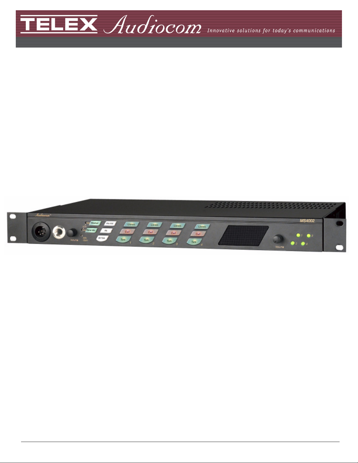
MS-4002 Master Station
User Manual
93507799000 Rev J July 2010
Page 2
PROPRIETARY NOTICE
The product information and design disclosed herein were originated by
and are the property of Bosch Security Systems, Inc. Bosch reserves all
patent, proprietary design, manufacturing, reproduction, use and sales
rights thereto, and to any article disclosed therein, except to the extent
rights are expressly granted to others.
COPYRIGHT NOTICE
Copyright 2010 by Bosch Security Systems, Inc. All rights reserved.
Reproduction, in whole or in part, without prior written permission from
Bosch is prohibited.
WARRANTY NOTICE
See the enclosed warranty card for further details.
CUSTOMER SUPPORT
Technical questions should be directed to:
Customer Service Department
Bosch Security Systems, Inc.
12000 Portland Avenue South
Burnsville, MN 55337 USA
Telephone: 800-392-3497
Fax: 800-323-0498
Factory Service: 800-553-5992 (Lincoln, NE)
This package should include the following
:
Qty Description Part Number
90107799000 (US)
1 MS-4002 Final Assembly
or
90107799001 (EU)
1 Power Cord 2504000300
1
1
1
Int’l Cordset, European
model only
1 1/4” Face Plate, Left,
Black
1 1/4” Face Plate, Right,
Black
550024000
9160-7353-002
9160-7353-003
1 MS-4002 User Manual 9350-7799-000
1 Statement of Conformity 38109-675
1 Warranty Card 38110-390
1 User Information 38109-668
2 Rackmount Bracket 9110-7353-000
RETURN SHIPPING INSTRUCTIONS
Customer Service Department
Bosch Security Systems, Inc. (Lincoln, NE)
Telephone: 402-467-5321
Fax: 402-467-3279
Factory Service: 800-553-5992
Please include a note in the box which supplies the company name,
address, phone number, a person to contact regarding the repair, the type
and quantity of equipment, a description of the problem and the serial
number(s).
SHIPPING TO THE MANUFACTURER
All shipments of product should be made via UPS Ground, prepaid (you
may request from Factory Service a different shipment method). Any
shipment upgrades will be paid by the customer. The equipment should
be shipped in the original packing carton. If the original carton is not
available, use any suitable container that is rigid and of adequate size. If
a substitute container is used, the equipment should be wrapped in paper
and surrounded with at least four (4) inches of excelsior or similar
shock-absorbing material. All shipments must be sent to the following
address and must include the Proof of Purchase for warranty repair.
Upon completion of any repair the equipment will be returned via
United Parcel Service or specified shipper, collect.
Factory Service Department
Bosch Security Systems, Inc.
8601 Cornhusker Hwy.
Lincoln, NE 68507 U.S.A.
Attn: Service
THE LIGHTNING
FLASH AND
ARROWHEAD
WITHIN THE
TRIANGLE IS A
WARNING SIGN
ALERTING YOU OF
“DANGEROUS
VOLTAGE” INSIDE
THE PRODUCT.
SEE MARKING ON BOTTOM/BACK OF PRODUCT
WARNING: APPARATUS SHALL NOT BE EXPOSED TO DRIPPING OR
SPLASHING AND NO OBJECTS FILLED WITH LIQUIDS, SUCH AS VASES,
SHALL BE PLACED ON THE APPARATUS.
WARNING: THE MAIN POWER PLUG MUST REMAIN READILY OPERABLE
CAUTION: TO REDUCE THE RISK OF ELECTRIC SHOCK, GROUNDING OF
THE CENTER PIN OF THIS PLUG MUST BE MAINTAINED.
WARNING: TO REDUCE THE RISK OF FIRE OR ELECTRIC SHOCK, DO NOT
EXPOSE THIS APPRATUS TO RAIN OR MOISTURE.
WARNING: TO PREVENT INJURY, THIS APPARATUS MUST BE SECURELY
ATTACHED TO THE FLOOR/WALL/RACK IN ACCORDANCE WITH THE
INSTALLATION INSTRUCTIONS.
CAUTION: TO REDUCE THE
RISK OF ELECTRIC SHOCK,
DO NOT REMOVE COVER.
NO USER-SERVICABLE
PARTS INSIDE. REFER
SERVICING TO QUALIFIED
SERVICE PERSONNEL.
This product is AC only.
THE
EXCLAMATION
POINT WITHIN
THE TRIANGLE IS
A WARNING SIGN
ALERTING YOU
OF IMPORTANT
INSTRUCTIONS
ACCOMPANYING
THE PRODUCT
Page 3

Important Safety Instructions
1. Read these instructions.
2. Keep these instructions.
3. Heed all warnings.
4. Follow all instructions.
5. Do not use this apparatus near water.
6. Clean only with dry cloth.
7. Do not block any ventilation openings. Install in accordance with the
manufacturer’s instructions.
8. Do not install near any heat sources such as radiators, heat registers, stoves, or
other apparatus (including amplifiers) that produce heat.
9. Do not defeat the safety purpose of the polarized or grounding-type plug. A
polarized plug has two blades with one wider than the other. A grounding type
plug has two blades and a third grounding prong. The wide blade or the third
prong are provided for your safety. If the provided plug does not fit into your
outlet, consult an electrician for replacement of the obsolete outlet.
10. Protect the power cord from being walked on or pinched particularly at plugs,
convenience receptacles, and the point where they exit from the apparatus.
11. Only use attachments/accessories specified by the manufacturer.
12. Use only with the cart, stand, tripod, bracket, or table specified by the
manufacturer, or sold with the apparatus. When a cart is used, use caution when
moving the cart/apparatus combination to avoid injury from tip-over.
13. Unplug this apparatus during lightning storms or when unused for long periods
of time.
14. Refer all servicing to qualified service personnel. Servicing is required when
the apparatus has been damaged in any way, such as power-supply cord or plug
is damaged, liquid has been spilled or objects have fallen into the apparatus, the
apparatus has been exposed to rain or moisture, does not operate normally, or
has been dropped.
Page 4

Page 5

Table
of
Contents
IMPORTANT SAFETY INSTRUCTIONS ...............................3
INTRODUCTION ............................................. 7
Description .............................................................7
Features ..................................................................7
Reference View .......................................................8
Default Jumper Settings .......................................10
INSTALLATION ............................................. 11
Direct Program Listen Enable/Disable ................11
Mounting ..............................................................11
Connections ..........................................................11
EXTERNAL PROGRAM INPUT AND PA OUTPUT ............12
ALANCED (BAL) OR UNBALANCED
B
(UNBAL) OPERATION ................................................12
Cables ...................................................................13
Power-up Check ...................................................14
Sidetone Adjustment .............................................15
Voice-Activated Microphone (Vox) Setup ............16
OPERATION ................................................... 17
Operation ..............................................................17
NORMAL VS. PROGRAMMING VS.
DVANCED PROGRAMMING MODE ..............................17
A
OLUME ADJUSTMENT ................................................18
V
R
ECEIVING CALLS .......................................................18
C
ALLING AN INTERCOM CHANNEL ...............................18
ICROPHONE MUTE DURING TALK ............................18
M
LL TALK ................................................................... 19
A
Public Address (PA) .............................................19
Turning the Program Input On and Off ................19
Using Mic Kill ......................................................20
Incoming Call Beep ON/OFF ...............................20
Test Tone ...............................................................20
Standard Programming ........................................21
Advanced Programming Using the MS-4002 .......22
CALL SIGNAL SEND AND RECEIVE, CHANNEL 1 .......... 22
C
ALL SIGNAL SEND AND RECEIVE, CHANNEL 2 .......... 23
ALL SIGNAL SEND AND RECEIVE, CHANNEL 3 .......... 23
C
ALL SIGNAL SEND AND RECEIVE, CHANNEL 4 .......... 23
C
P
ROGRAM INTERRUPT 1 ............................................. 24
ROGRAM INTERRUPT 2 ............................................. 24
P
ROGRAM INTERRUPT 3 ............................................. 24
P
P
ROGRAM INTERRUPT 4 ............................................. 24
NCOMING CALL BEEP, HEADSET ............................... 25
I
NCOMING CALL BEEP, PANEL SPEAKER .................... 25
I
L
ISTEN 2 TO SPEAKER 1 ............................................. 25
ISTEN 3 TO SPEAKER 1 ............................................. 25
L
ISTEN 4 TO SPEAKER 1 ............................................. 26
L
Specifications ........................................................27
Page 6

Page 7

CHAPTER 1
Introduction
Description
The MS-4002 is a complete 4-channel master station and system power supply (24 VDC, up to 3.5Amps total power) in a
single unit. Simply plug it into any AC power outlet from 100 to 240 volts, add a microphone or headset, connect intercom
stations to the backpanel, and it’s ready to communicate. It has 1-, 2-, 3- and 4-channel connectors, so a separate breakout
panel is not needed to mix multiple intercom stations. The MS-4002 fits in a standard 19-inch equipment rack and is 1 RU
(Rack Unit) high. A basic MS-4002 can communicate with four (4) intercom channels. This number can be increased by
connecting an optional EMS-4001 Expansion Station. Each EMS-4001 adds four (4) channels, and up to four (4) of these
expansion stations can be connected for a total of 20 channels.
Features
• Auto-Sensing Headset Connector
Built-in auto-sensing headset connectors that dynamically
determines whether the headset connected to the system is
dynamic or electret.
• Speaker Station or Headset Station
Uses the built-in speaker for listening and adds an optional
Telex MCP-90 series gooseneck panel microphone for
talk-back. Turn off the speaker volume and plug in any
Telex headset for private communication.
• PA (Public Address) Output, with PA Key
Uses the intercom microphone to talk over a PA system.
• Back-lit Keys
Uses back-lit keys to improve visibility in low-light
environments.
• Incoming Call Indications
Uses red flashing call lights with an optional beep tone for
call indications, if desired.
• Mic Kill Key
Turns off all microphones for a specific channel to
quickly clear traffic on the channel.
• Program Input for each Channel
Connects any line-level audio source for monitoring
speaker or headset, or for routing to an intercom channel.
The program audio to the channel can be set to interrupt
while the MS-4002 operator is talking on the channel.
• Listening with Externally Powered Speakers
Connect externally powered speakers and monitor
channels 1, 2, 3, and 4.
• Expandable
Adds more channels by connecting optional EMS-4001
Expansion Stations. Each EMS-4001 adds four (4)
additional powered channels (up to 20 channels).
• Clear - ComCompatible
Runs in unbalanced mode.
7
Page 8
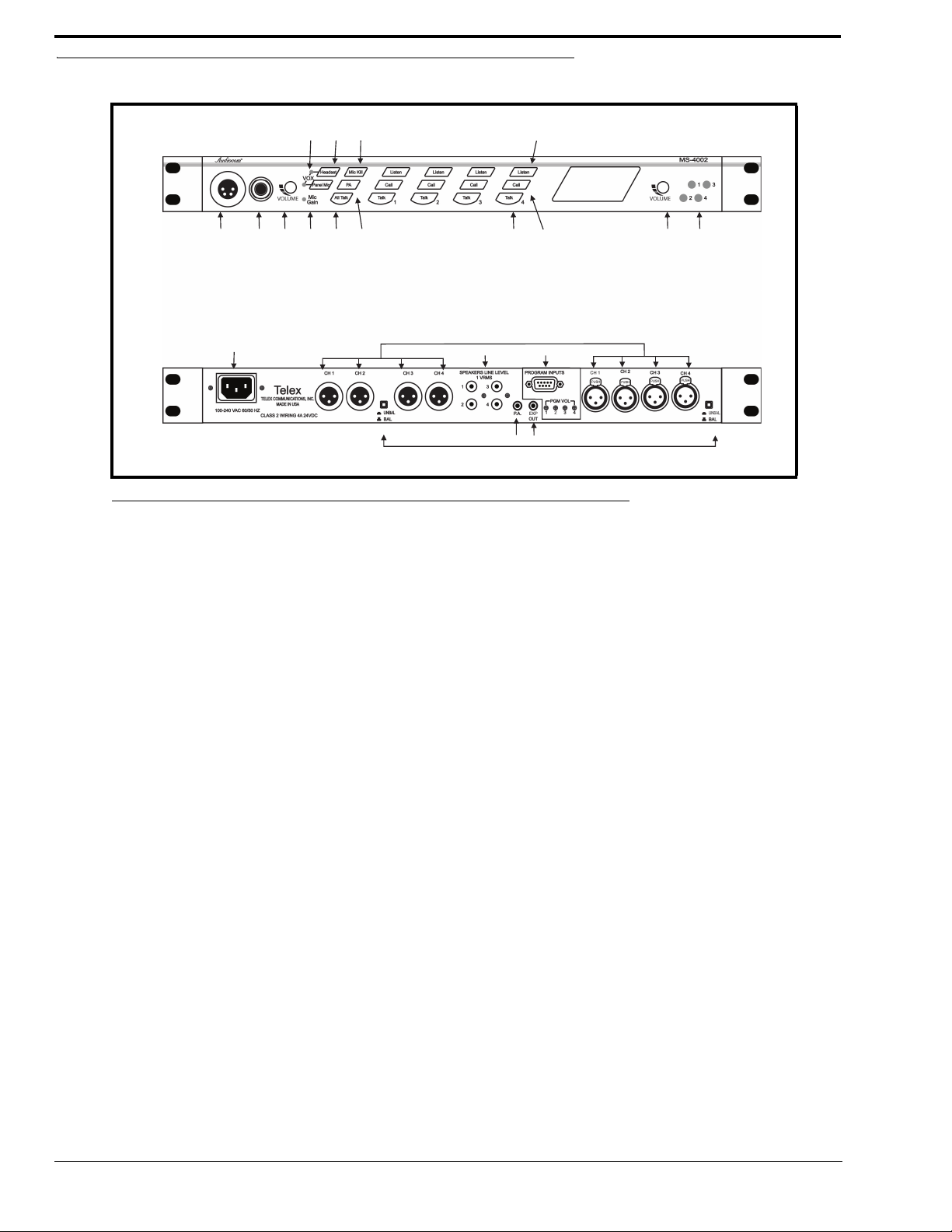
Reference View
1 23678 10 11 13 14
459 12
21
18
19
20
16
17
15
FIGURE 1. MS-4002 Reference View
1. Auto-sensing Mic Headset Connector -
Accepts headsets with monaural headphones; either dynamic and electret microphone.
2. Panel Mic Connector -
Accepts an electret gooseneck microphone. The model MCP-90 series panel mic connector is a 1/4” stereo plug, with
a threaded shaft for easy installation.
3. Vo l u m e Contro l -
Adjusts headphone volume only.
4. Vox Trimmers -
Used with the voice-activated microphone feature. Separate trimmers to adjust the voice activation level for the
headset and panel microphones.
5. Headset and Panel Mic Keys -
Used to manually activate either the headset or panel microphone, whichever is being used.
6. Mic Gain -
Used to adjust the level of audio sent from the microphone.
7. All Talk Key -
Used to talk to any station on any channel. This includes all the MS-4002 channels and any channels connected
through an EMS-4001 Expansion Station.
8. PA Ke y -
If the MS-4002 is connected to a PA system, this key may be used to talk over the public address system.
9. Mic Kill Key -
Used to turn off the microphones of any intercom station on a channel. Also, used to activate program inputs and the
audible beep feature for incoming calls.
10. Intercom Talk Keys -
Momentary or latching (hands-free) operation possible.
11. Call Keys -
Used to place calls on intercom channels and to indicate incoming calls.
12. Intercom Listen Keys -
Momentary or latching (hands-free) operation possible.
8
Page 9

13. Speaker Volume Control -
Volume control adjusts the level to the front panel speaker. If an external speaker is used, volume must be adjusted at
the speaker.
14. Channel Status Indicators -
The indicators are green for normal operation and red when there is an overload or short circuit. Once the fault is
resolved, the system will Auto-reset.
15. Universal AC Power Input -
The MS-4002 accepts any input power in the range of 100-240 VAC, 50/60 Hz.
16. Program Inputs Connector and Trimmers -
Each intercom channel has its own program input and level adjust trimmer. The program inputs may be turned on or
off via the front panel and they may be set to interrupt during talk, if desired.
17. Intercom Line Connector -
Two (2) connectors are provided for each channel for loop-through connection of 1-channel intercom stations.
18. PA O utput -
Connects to a public address system.
19. Expansion Out Connector -
Connects to an EMS-4001 Expansion Station.
20. Speaker Output Jacks -
May be used with externally-powered loudspeakers for monaural or binaural listening configurations.
21. Balanced/Unbalanced Selector Switches -
The selector switches set the MS-4002 for compatibility with either Audiocom or Clear-Com channel connector
pin-outs, channel power requirements, and call signaling requirements. Both switches must be in the same position.
9
Page 10

Default Jumper Settings
JP6
JP3
JP4
JP7
JP2
JP1
JP5
pin 1
pin 1
pin 1
pin 1
pin 1
FIGURE 2. Default Jumper Settings
NOTE: These jumpers settings apply only to board 9030-7799-000 Rev G or higher.
Description Default Position
JP1 Panel Microphone Power Connection Shorted on Pins 1&2
JP2 Headset Microphone Power Connection Shorted on Pins 1&2
JP3 Channel 2 Line Connection Format Select Shorted on Pins 1&2
JP4 Channel 4 Line Connection Format Select Shorted on Pins 1&2
JP5 Panel Microphone Audio Connection Shorted on Pins 2&3
JP6 Channel 1 Line Connection Format Select Shorted on Pins 1&2
JP7 Channel 3 Line Connection Format Select Shorted on Pins 1&2
10
Page 11

CHAPTER 2
Installation
Direct Program Listen Enable/Disable
By default, each MS-4002 program input can be heard locally by all intercom stations. Program input routing to the intercom
channels can be turned on or off via the MS-4002 front panel programming. For more information on programming, see
“Standard Programming” on page 21 and “Advanced Programming Using the MS-4002” on page 22.
Mounting
The MS-4002 mounts in a standard 19-inch equipment rack and is 1 RU (Rack Unit) high. When mounting the MS-4002,
install the supplied black face plates on the appropriate sides. The face plates should be mounted with the grooves on the top,
see Figure 1.
NOTE: After all components are connected, you may have to perform the sidetone adjustment, see “Sidetone
Adjustment” on page 15. With the MS-4002 being rack mounted, you may not be able to access the sidetone
trimmers. In this case, you can position the MS-4002 in the rack and make all required connections. Then, adjust
the sidetone trimmers before installing and tightening all rack mount screws.
Connections
Refer to the following paragraphs and sample connection drawings on page 6, 7 and 8.
11
Page 12

External Program Input and PA Output
100-240VAC 60/50 HZ
100-240VAC 60/50 HZ
3
3
5
5
PROGRAM
INPUTS
PROGRAM
INPUTS
PGMVOL
PGMVOL
4
4
6
6
3
3
4
4
5
5
6
6
LINE LEVEL
1VRMS
LINE LEVEL
1VRMS
EXP
OUT
EXP
OUT
EXP
IN
EXP
IN
UNBAL
BAL
UNBAL
BAL
CLASS 2WIRING 2A 24VDC
CLASS 2WIRING 2A 24VDC
UNBAL
BAL
UNBAL
BAL
TELEX COMMUNICATIONS, INC.
MADE IN USA
TELEX COMMUNICATIONS, INC.
MADE IN USA
Telex
®
Telex
®
CH 1-2
XP-USPG
PA
OUT
PGM
1 IN
PGM
2 IN
BACK
FRONT
CH 3 - 6
XP-4PGM
BACK
FRONT
PGM
3 IN
PGM
4 IN
PGM
5 IN
PGM
6 IN
CH 7 - 10
XP-4PGM
BACK
FRONT
PGM
7 IN
PGM
8 IN
PGM
9 IN
PGM
10 IN
5 555
5 55
5 65
5
2
2
2
3
4
1
1
1
1
1
1
1
1
1
1
4
4
TO TW-7W SPLITTERS
(FOR HOME RUN CONNECTION)
OR TO A STRING OF
INTERCOM STATIONS
(DAISY CHAIN CONNECTION)
TO TW-7W SPLITTERS
(FOR HOME RUN CONNECTION)
OR TO A STRING OF
INTERCOM STATIONS
(DAISY CHAIN CONNECTION)
CH 1
CH 2
CH 5
CH 6
CH 7
CH 8
CH 9
CH 10
CH 11
CH 12
TO ANOTHER EMS-4001
1
1
CH 3
CH 4
Connections for external program input and PA output are shown in Figure 1, EMS-4001 Expansion Station Connection
(optional component).
REFERENCE:Refer to the EMS-4001 User Instruction Manual (p/n 93507713000) for detailed connection information.
Balanced (BAL) or Unbalanced (UNBAL) Operation
Figure 1. Example of MS-4002 and EMS-4001 system.
Balanced or Unbalanced operation determines if the MS-4002 is compatible with Clear-Com equipment. If the unit is
configured to Balanced operation it can only use Telex equipment. If the unit is set to Unbalanced operation, it works with
Clear-Com or Clear-Com compatible equipment only.
NOTE: There are two (2) switches on the MS-4002 unit that control the Balanced/Unbalanced operation. You must set
12
both of these switches in the same position for proper operation, see Figure 2.
Page 13

Figure 2. MS-4002 Back Panel Balanced and Unbalanced Operation Switches
BAL / UNBAL
buttons
Default: Balanced (BAL) Operation (Out)
Switch position: out (not depressed) Balanced (Audiocom)
Switch position: in (depressed) Unbalanced (Clear-Com)
Cables
The numbers below correspond to the cable numbers in the connection drawings shown in Figure 3.
1. 1-channel intercom cable. Sold separately. Use Telex ME cables, below.
ME-25: 25’ (7.6 m) cable with Male and Female 3-pin XLR connectors.
ME-50: 50’ (15.2 m) cable with Male and Female 3-pin XLR connectors.
ME-100:100’ (30.4 m) cable with Male and Female 3-pin XLR connectors.
NOTE: When connecting from the MS-4002 to a TW-7W, keep cables as short as possible. Also, heavier gauge wire
is recommended.
2. 2-channel intercom cable. Sold separately. Use Telex ME cables, below.
ME-25/2: 25’ (7.6 m) cable with Male and Female 6-pin XLR connectors.
ME-50/2: 50’ (15.2 m) cable with Male and Female 6-pin XLR connectors.
ME-100/2: 100’ (30.4 m) cable with Male and Female 6-pin XLR connectors.
3. Y adapter cable. Sold separately. Use Telex CA-23-16.
3 ft. (0.91 m) speaker cable with RCA plugs. One supplied with each SPS2001, and SPK-2000.
4. 18” (457 mm) EXP IN/OUT cable, stereo mini-plug to stereo mini-plug. One (1) supplied with each EMS-4001.
5. Shielded patch cable, 9-pin Male D-sub to 9-pin Female D-sub. Customer local purchase. Available at most
electronic shops. Note, all pins must be connected straight through: do not use an RS232 computer cable.
6. Shielded patch cable, stereo miniplug to stereo miniplug. Customer local purchase. Available at most electronic
stores.
7. Shielded audio cable. Must have male 3-pin XLR connector at one (1) end for connection to the XP-USPG or SP-
4PGM program inputs. Pin-out for program inputs as follows:
Pin 1: common
Pin 2: + program input
Pin 3: - program input
13
Page 14

8. Shielded audio cable. Must have male 3-pin XLR connector at one (1) end for connection to the XP-USPG PA
Pair 1
Pair 1
Pair 1
Pair 2
Pair 2
Pair 2
Pair 3
Pair 3
TYPICAL 2-CHANNEL CABLE WIRING
“Y” CABLE WIRING
TYPICAL 1-CHANNEL CABLE WIRING
Cable Type: 22AWG Stranded, 3-Pair Twisted-wire, with Shield
Pin 3: Channel 1 Audio / Power
Pin 4: Channel 1 Audio / Power
Pin 5: Channel 2 Audio / Power
Pin 6: Channel 2 Audio / Power
: Earth ground
Connector Type: 6-Pin XLR Audio (Neutrik only, not compatible with 6-pin Switchcraft)
Pin 1: Channel 1 & 2 Common
Pin 2: No connection
*
Shield
Cable Type: 22AWG Stranded, 2-Pair Twisted-wire, with Shield
Channel Audio / Power
Pin 3: Channel Audio / Power
: Earth ground
Connector Type: 3-Pin XLR Audio (Neutrik or Switchcraft)
Pin 1: Common
Pin 2:
*
Shield
* Standard cables are generally constructed using a male connector at one end and a
female connector at the other end. This allows several cables to be interconnected to
create longer cable runs.
Audiocom power supplies use a 3-pin male Neutrik connector for
each channel. Audiocom wallplates use male Neutrik connectors.
Audiocom master stations, speaker stations and belt packs
also typically provide both a male and female Neutrik connector for each intercom
channel. This permits loop-through connection of several intercom stations using the
standard cables.
Use second drain wire if available, or add an extra section of wire.
Ch1
Ch2
Denotes twisted pair.
Denotes twisted pair.
Denotes shield.
Denotes shield.
33
3
3
22
2
2
1
1
1
Shield Shield
Case
Shield
44
4
33
3
66
6
55
5
1
1 (Both wires)
1 (Both wires)
1 (Both wires)
Shield
Shield
Shield
output. Pin-out for PA output as follows:
Pin 1: common
Pin 2: + PA output
Pin 3: - PA output
9. 18” (457 mm) CHANNEL OUTPUT cable, 15-pin Male D-sub to 15-pin Female D-sub. One supplied with each
XP-ES4000.
REFERENCE:Optional component, see EMS-4001 User Manual (p/n 93507713000) for more detailed connection
information.
Power-up Check
Plug in the MS-4002. When power is first applied to the unit, it performs a power-up reset (front panel indicators cycle through
all possible colors and then turn off). This verifies the general operation of the intercom station and indicators.
Figure 3. Audiocom Intercom Cables
14
Page 15

Sidetone Adjustment
Channel
4
Sidetone
Channel
3
Sidetone
Channel
2
Sidetone
Channel
1
Sidetone
The MS-4002 uses full-duplex audio (the same as a conventional telephone line) in which the talk and listen audio are sent and
received on the same line. When you talk on a channel, you hear your own voice in the speaker or headphones. This is called
sidetone. If you are using the MS-4002 with a microphone and speaker, sidetone could cause unwanted feedback, since the
microphone may pick up your returned voice audio and re-amplify it. This could also happen if you are using a headset where
the ear cushions do not completely cover the ears. In either of these cases, you should minimize the amount of sidetone.
NOTE: If you are using headphones that completely enclose the ears, a certain amount of your own voice level is
desirable to overcome the muffled sensation when talking.
Figure 4. Sidetone Adjustment diagram (MS-4002 bottom view)
To Adjust the Sidetone, do the following:
If you are using a speaker and microphone, or open-ear style headphones, adjust sidetone as follows:
1. Simultaneously press the All Talk and PA keys to activate the test tone.
2. Tap t he channel 1 Call key to send the test tone on channel 1.
3. Increase the volume until you can hear the test tone
NOTE: For the volume control descriptions, see Figure 1, “MS-4002 Reference View,” on page 8.
4. Using a small, standard screwdriver, adjust the channel 1 sidetone (Figure 4) through the access hole in the bottom
of the MS-4002 to minimize the tone volume.
5. Tap t he channel 1 Call key to turn off the test tone on channel 1 when finished.
6. Tap t he channel 2 Call key, repeat the adjust for the channel 2 sidetone.
7. Tap any other key, except a Call key, to turn off the test tone when finished.
To set channels 3 and 4, do the following:
> Repeat steps 1 through 7, above.
15
Page 16

If you are using headphones that completely enclose the ears, adjust sidetones as follows:
1. Tap t he Headset key to turn the headset microphone on.
2. Tap t he channel 1 Talk key to turn it on.
3. While speaking into the microphone, use a small flat-bladed screwdriver to adjust the channel 1 Talk key to turn it so
you hear your voice at an acceptable level in the headphones.
4. Tap t he channel 1 Talk key to turn it off when finished.
5. Tap t he channel 2 Talk key to turn it on, and adjust the channel 2 sidetone as for channel 1.
6. Tap t he channel 2 Talk key to turn it off when finished.
To set channels 3 and 4, do the following:
> Repeat steps 1 through 6, above.
Voice-Activated Microphone (Vox) Setup
If you are going to use Vox, you must adjust its level for proper operation. If the Vox level is too low, room noise activates the
microphone. If the Vox level is too high, the microphone does not activate when you begin talking.
To check and set the Vox level, do the following:
1. If you are using a headset, tap the Headset key twice to turn on headset Vox.
OR
If you are using a panel microphone, tap the Panel Mic key twice to turn on panel mic Vox.
Whichever key you tap, it will glow orange when the microphone is off and flickers or turn green when the sound is
picked up by the microphone.
2. Position the microphone at its normal operation location.
If you are using a headset, put the headset on and position the microphone about three fingers length from your
mouth.
3. Insure that background noise is at the normal operating level.
Do not speak into the microphone.
4. If the Headset or Panel Mic key is constantly glowing orange, turn the Vox trimmer clockwise until the key begins to
flicker green (mic activating), then turn the trimmer slightly back in the counterclockwise direction until the Panel
Mic key just returns to steady orange (mic off).
If you are wearing a headset, make sure that breathing and movement do not cause the Panel Mic key to flicker green.
If they do, adjust the Vox control slightly more in the counterclockwise direction to eliminate this.
5. Speak into the microphone in a normal voice, and verify the headset key immediately turns green when you talk.
If the key does not turn green, move the microphone closer to your mouth.
NOTE: If you are still unable to get satisfactory results, it may be that the microphone does not have the directional
characteristics required for the noise level in the room. A directional, or cardioid, microphone is
recommended when using Vox.
6. To return the MS-4002 to normal operation, tap the Mic Kill key.
16
Page 17

CHAPTER 3
Operation
Operation
NOTE: A quick-reference to the following operating features are shown in Table 5.
Normal vs. Programming vs. Advanced Programming Mode
The MS-4002 has three operating modes: normal operating mode, standard programming mode (see page 21), and advance
programming mode (see page 22). In normal operating mode, the Mic Kill key will be unlit, and in programming mode it is lit
continuously.
To return the MS-4002 to normal operation, do the following:
> If it has been left in programming mode, tap the Mic Kill key.
NOTE: For information on accessing Advanced Programming Mode, see “Advanced Programming Using the MS-
4002” on page 22
17
Page 18

Volum e A djus t m ent
If you are using a headset, adjust the intercom listen level with the left volume control on the front panel of the MS-4002. If
you are using a speaker, adjust the intercom listen level with the right volume control next to the speaker. External speakers
requires their own volume controls.
Receiving Calls
1. When there is an incoming call signal on a channel, the Call key for that channel flashes red. There also isa beep tone
if the beep feature has been activated
NOTE: See “Incoming Call Beep ON/OFF” on page 20.
2. Activate the microphone:
• If you are using a dynamic-mic headset or an electret-mic headset, tap the Headset key to turn the mic on.
• If you are using a panel-mounted microphone, tap the Panel Mic key to turn the mic on.
NOTE: You can also use the voice-activated microphone feature. See “Voice-Activated Microphone (Vox) Setup”
on page 16.
3. Tap on the Talk and Listen keys for the calling channel and begin your conversation.
4. Tap t he keys off when finished.
NOTE: When you tap the Headset key, or the Panel Mic key, or any Talk or Listen key, it will lock in the on position.
Then tap the key again to turn it off. For momentary activation, press and hold the key. It will remain on as long
as you hold it and then turn off when you release it.
Calling an Intercom Channel
1. Press and hold the Call key for the channel that you want to call.
An inaudible call signal is sent, and the listen key for that channel automatically turns on in preparation to receive a
verbal response.
2. When you hear a response, release the Call key.
3. If you are using manual microphone activation instead of Vox, make sure your microphone is on:
• for a headset mic, tap the Headset key to turn it on.
• for a panel-mounted microphone, tap the Panel Mic key to turn the mic on.
4. Tap on the Tal k key for the channel you called to begin your conversation.
5. Tap off your Tal k and Listen keys to end the conversation.
Microphone Mute During Talk
To mute the microphone while talking, do the following:
1. Tap either the Headset key or the Panel Mic key.
2. Tap t he key again to turn the microphone back on.
If you are using Vox, tap the key twice to reactivate Vox.
18
Page 19

All Talk
You can talk to all intercom stations that currently have their listen keys activated. This applies to all channels of the
MS-4002, as well as all the talk channels of any EMS-4001 Expansion Stations.
To use the all talk function, do the following:
NOTE: If you are using manual microphone activation instead of Vox, make sure the proper microphone switch is
turned on (either Headset or Panel Mic).
1. Press and hold the All Talk key while talking.
2. Release the All Talk key when finished.
NOTE: To insure that the All Talk key is never accidently left in the on position, it does not latch.
Public Address (PA)
You can create a PA system with the MS-4002 if the PA output on the back panel of the MS-4002 is connected to a public
address system.
To use the PA system function, do the following:
NOTE: If you are using the manual microphone activation instead of Vox, make sure the proper microphone switch
is turned on (either Headset or Panel Mic).
1. Press and hold the PA key while talking.
2. Release the key when finished.
NOTE: To insure that the PA key is never accidently left in the on position, it does not latch.
Turning the Program Input On and Off
To turn the program input on and off, do the following:
1. Insure the program inputs have been connected at the back panel and the program sources are ON.
2. Press and hold the Mic Kill key for two (2) seconds, then release it.
It should now be glowing green to indicate the MS-4002 is in programming mode.
3. The current status of the program inputs is indicated by the Talk keys:
a. If Channel 1 talk is lit, program 1 is activated to channel 1.
b. If Channel 2 talk is lit, program 2 is activated to channel 2.
c. Tap either Tal k key to turn the program input for that channel on or off.
NOTE: You can also turn the Program Input ON and OFF on channels 3 and 4.
4. When the program inputs are configured as desired, tap the Mic Kill key to exit programming mode and return to
normal operation.
5. Adjust Program 1, 2, 3, and 4 via the trimmers on the rear panel of the MS-4002.
NOTE: See “MS-4002 Reference View” on page 8.
19
Page 20

Using Mic Kill
If the Mic Kill feature has been enabled, you can use it to deactivate all talk keys on a single channel or on all channels. This
feature is useful when a remote talk key has been left ON and is causing unwanted noise on a channel.
To use Mic Kill, do the following:
1. Tap t he Mic Kill key.
It blinks green.
2. Tap t he Ta lk or Listen key for a channel to turn off all talk keys on that channel. Or, tap the All Talk key to turn off
all talk keys.
The key you tap turns green and the Mic Kill signal is sent.
3. Tap t he Mic Kill to exit.
Incoming Call Beep ON/OFF
Normally, incoming calls are indicated by red-flashing Call keys.
To enable the optional beep tone, do the following:
1. Press and hold the Mic Kill key for two (2) seconds, then release it.
It glows green to indicate the intercom station is in programming mode.
2. Tap any Call key on the MS-4002 to turn the beep feature on or off.
NOTE: This feature affects all channels.
3. Tap t he Mic Kill key to return to normal operation
Test Ton e
The MS-4002 can generate a test tone, which can be used to verify intercom channel operation after installation or to locate a
malfunction. This test tone is also used for the sidetone adjustment.
To use the test tone, do the following:
1. Simultaneously press the All Talk and PA keys to activate the test tone.
2. Tap t he Call key for the channel you want to test (can be either an MS-4002 channel or an EMS-4001 channel).
3. Verify the test tone can be heard at all intercom stations on the channel.
4. Replace any defective cable or intercom station where the test tone is being lost.
5. Tap the same Call key to stop the test signal on that channel.
6. Press any key except a Call key, to turn off the test tone.
20
Page 21

Standard Programming
Standard programming without entering program mode on the MS-4002
To enter Standard Programming, do the following:
1. Press and hold the Mic Kill key for about two (2) seconds, then release it.
It glows green to indicate the intercom station is in programming mode..
TABLE 5. Standard Programming Descriptions.
Description Action
Reset MS-4002 Press All Talk and Listen 1
Test Signal On Press All Talk and PA, then tap Call
Test Signal Off Tap Call, then tap any other key
Mic Latched On Tap Headset or Panel Mic (key is green)
Mic Latched Off Tap Headset or Panel Mic
Mic Momentary On Hold Headset or Panel Mic
Mic Momentary Off Release Headset or Panel Mic
VOX Mode On Tap Twice; Headset or Panel Mic (key is orange)
VOX Mode Off Tap Headset or Panel Mic
All Talk On Hold All Talk when Headset or Panel Mic is lit (All Talk key is green)
All Talk Off Release All Talk
Public Address Hold PA when Headset or Panel Mic is lit (PA key is green)
Mic Kill, One Channel
Mic Kill, All Channels
Program On Hold Mic Kill, then tap channel’s Talk key (key is green). Tap Mic Kill to exit
Program Off Hold Mic Kill, then tap the channel’s Talk key. Tap Mic Kill to exit.
Audible Call Alert On Hold Mic Kill, then tap Call (all Call keys are red). Tap the Mic Kill to exit
Audible Call Alert Off Hold Mic Kill, then tap Call. Tap Mic Kill to exit.
Turn Mic Kill Key Off Tap Mic Kill
Talk Latched On Tap Talk (key is green)
Talk Latched Off Tap Talk
Talk Momentary On Hold Talk
Talk Momentary Off Release Talk
Call Signal On Hold Call
Call Signal Off Release Call
Receive Call Signal Receive call (call key is red)
Listen Latched On Tap Listen (key is green)
Listen Latched Off Tap Listen
Listen Momentary On Hold Listen
Listen Momentary Off Release Listen
Tap Mic Kill, then tap Talk or Listen (Mic Kill key will blink green and the
Talk and Listen keys are green. Tap Mic Kill to exit.
Tap Mic Kill, then tap All Talk (Mic Kill key will blink green and all Talk/
Listen keys are green). Tap Mic Kill to exit.
21
Page 22

Advanced Programming Using the MS-4002
Advanced Programming for the MS-4002 has moved from the Internal DIP switches (MS-2002 and previous models) to the
front panel of the unit. Using Figure 6 you can program your MS-4002 with existing and new functionality.
Figure 6. Advanced Programming Buttons Diagram
To access Advanced Programming Mode on the MS-4002, do the following:
> Press and hold both Mic Kill and PA for five (5)seconds.
After 10 seconds of inactivity, the system returns back to Operation Mode.
NOTE: A red and green flashing All Talk button signals operation is in Advanced Programming Mode
Each programming function , as well as how to enable and disable the function, is described below.
NOTE: You must be in the Advanced Programming Mode to perform the following configurations.
Call Signal Send and Receive, Channel 1
The Call Signal Send and Call Signal Receive has been combined into one (1) function that is enabled and disabled.
Default Setting: Call Signal Send and Receive, Channel 1 enabled.
To enable the Signal Send and Signal Receive for Channel 1, do the following:
> Press Channel 1 Call button.
The button is backlit with a bright red light. The Signal Send and Signal Receive for Channel 1 is enabled.
To disable the Signal Send and Signal Receive for Channel 1, do the following:
> When lit red, press Channel 1 Call button.
The red back-light dims. The Signal Send and Signal Receive for Channel 1 is disabled.
22
Page 23

Call Signal Send and Receive, Channel 2
The Call Signal Send and Call Signal Receive has been combined into one (1) function that is enabled and disabled.
Default Setting: Call Signal Send and Receive, Channel 2 enabled.
To enable the Signal Send and Signal Receive for Channel 2, do the following:
> Press Channel 2 Call button.
The button is backlit with a bright red light. The Signal Send and Signal Receive for Channel 2 is enabled.
To disable the Signal Send and Signal Receive for Channel 2, do the following:
> When lit red, press Channel 2 Call button.
The red back-light dims. The Signal Send and Signal Receive for Channel 2 is disabled.
Call Signal Send and Receive, Channel 3
The Call Signal Send and Call Signal Receive has been combined into one (1) function that is enabled and disabled.
Default Setting: Call Signal Send and Receive, Channel 3 enabled.
To enable the Signal Send and Signal Receive for Channel 3, do the following:
> Press button Channel 3 Call button.
The button is backlit with a bright red light. The Signal Send and Signal Receive for Channel 3 is enabled.
To disable the Signal Send and Signal Receive for Channel 3, do the following:
> When lit red, press button Channel 3 Call button.
The red back-light dims. The Signal Send and Signal Receive for Channel 3 is disabled.
Call Signal Send and Receive, Channel 4
The Call Signal Send and Call Signal Receive has been combined into one (1) function that is enabled and disabled.
Default Setting: Call Signal Send and Receive, Channel 4 enabled.
To enable the Signal Send and Signal Receive for Channel 4, do the following:
> Press Channel 4 Call button.
The button is backlit with a bright red light. The Signal Send and Signal Receive for Channel 4 is enabled.
To disable the Signal Send and Signal Receive for Channel 4, do the following:
> When lit red, press Channel 4 Call button.
The red back-light dims. The Signal Send and Signal Receive for Channel 4 is disabled.
23
Page 24

Program Interrupt 1
NOTE: You must turn PGM Input on before using Program Inputs, see “Turning the Program Input On and Off” on
page 19
Default: Program 1 Interrupt is disabled.
To enable Program 1 Interrupt, do the following:
> Press Channel 1 Talk button.
The button is backlit with a bright green light. The Program 1 Interrupt is enabled.
To disable the Program 1 Interrupt, do the following:
> When lit green, press Channel 1 Talk button.
The green back-light dims. The Program 1 Interrupts disabled.
Program Interrupt 2
Default: Program 2 Interrupt is disabled.
To enable Program 2 Interrupt, do the following:
> Press the Channel 2 Talk button.
The button is backlit with a bright green light. The Program 2 Interrupt is enabled.
To disable the Program 2 Interrupt, do the following:
> When lit green, press the Channel 2 Talk button.
The green back-light dims. The Program 2 Interrupt is disabled.
Program Interrupt 3
Default: Program 3 Interrupt is disabled.
To enable Program 3 Interrupt, do the following:
1. Press the Channel 3 Talk button.
The button is backlit with a bright green light. The Program 3 Interrupt is enabled.
To disable the Program 3 Interrupt, do the following:
1. When lit green, press the Channel 3 Talk button.
The green back-light dims. The Program 3 Interrupt is disabled.
Program Interrupt 4
Default: Program 4 Interrupt is disabled.
To enable Program 4 Interrupt, do the following:
> Press the Channel 4 Talk button.
The button is backlit with a bright green light. The Program 4 Interrupt is enabled.
To disable the Program 4 Interrupt, do the following:
> When lit green, press the Channel 4 Talk button.
The green back-light dims. The Program 4 Interrupt is disabled.
24
Page 25

Incoming Call Beep, Headset
Default: Incoming Call Beep, Headset Enabled (on)
To enable the Incoming Call Beep, do the following:
> Press the Headset button.
The key is backlit with a bright green light. Incoming Call Beep, Headset is enabled.
To disable the Incoming Call Beep, Headset, do the following:
> When lit red, the Headset button.
The key is backlit with a dim red light. Incoming Call Beep, Headset is disabled.
Incoming Call Beep, Panel Speaker
Default: Incoming Call Beep, Panel Speaker Enabled (on)
To enable the Incoming Call Beep, do the following:
> Press the Panel Mic button.
The key is backlit with a bright green light. Incoming Call Beep, Panel Speaker is enabled.
To disable the Incoming Call Beep, Panel Speaker, do the following:
> When lit red, the Panel Mic button.
The key is backlit with a dim red light. Incoming Call Beep, Panel Speaker is disabled.
Listen 2 to Speaker 1
Default: Listen 2 to Speaker 1 Disabled (off)
To enable Listen 2 to Speaker 1, do the following:
> Press the Channel 2 Listen button.
The key is backlit with a bright green light. Listen 2 to Speaker 1 is enabled.
To disable the Listen 2 to Speaker 1, do the following:
> Press the Channel 2 Listen button.
The green back-light dims. Listen 2 to Speaker 1 is disabled.
Listen 3 to Speaker 1
Default: Listen 3 to Speaker 1 Disabled (off)
To enable Listen 3 to Speaker 1, do the following:
> Press the Channel 3 Listen button.
The key is backlit with a bright green light. Listen 3 to Speaker 1 is enabled.
To disable the Listen 3 to Speaker 1, do the following:
> Press the Channel 3 Listen button.
The green light dims. Listen 3 to Speaker 1 is disabled.
25
Page 26

Listen 4 to Speaker 1
Default: Listen 4 to Speaker 1 Disabled (off)
To enable Listen 4 to Speaker 1, do the following:
> Press the Channel 4 Listen button.
The key is backlit with a bright green light. Listen 4 to Speaker 1 is enabled.
To disable the Listen 4 to Speaker 1, do the following:
> Press the Channel 4 Listen button.
The green back-light dims. Listen 4 to Speaker 1 is disabled.
26
Page 27

Specifications
General
Power Requirements
AC Input:
100-240VAC, 50/60Hz
Channel Power:
24VDC nominal (12 - 30VDC), up to 1Amp per channel (max. 3.5
Amps)
Dimensions
1.75” (44.5mm)high x 19” (483mm) wide x 11.25” (286 mm) deep
Wei gh t
Approximately 5lb. (2.25kg)
Environmental Requirements
Storage:
-20° C to 80°C (-4°F – 176°F); 0% to 95% humidity, non-condensing
Operating
-15° C to 60°C (5°F – 140°F); 0% to 95% humidity, non-condensing
Dynamic/Electret Mic Headset
Microphone
50-200 Ohm, dynamic (balanced or unbalanced) - 2k Ohm, electret
Headphones
150-600 Ohm, monaural
Connector Type
XLR-4M connector
Input Level
-55dBu (nominal), dynamic
9mV, electret
Panel Microphone: Input
Microphone Type
Electret condenser (MCP-90 series microphone)
Power
Phantom (+12VDC)
Nominal Level
-42dBu
Maximum Level
-25dBu
Connector Type
1/4” stereo plug with threaded shaft
Program Input
Input Level
100mV maximum
Vo lt ag e G ai n
20 ± 3dB
Output Level (to intercom channel)
1.0Vrms nominal, 2.3 Vrms max.
Input Impedance
75k Ohm
Common Mode Rejection
Greater than 50dB
Connector Type
9-pin female D-sub (DE9S)
Pin 1
Pin 2
Pin 3
Pin 4
Pin 5
Pin 6
Pin 7
Pin 8
Pin 9
Input Channels, Balanced Mode
Output Level
1Vrms nominal
Input Impedance
300 Ohms
Bridging Impedance
Greater than 10,000 Ohms
Sidetone
-40dB, 35dB adjustable range
Call Signaling
Send:
20kHz ± 100Hz 0.5Vrms ± 10%
Receive:
20kHz ± 800Hz, 100mVrms
Mic Kill Frequency
Send
24 kHz ± 100Hz, 0.5Vrms ± 10%
Receive
24kHz ± 800Hz, 100mVrms
Noise Contribution
Less than -70dB
Common Mode Rejection Ratio
Greater than 50dB
Connector Type
One XLR-3M and XLR -3F pair, wired in parallel, for each channel
(permits loop-through connection). Four (4) total channels.
Pin 1
Pin 2
Pin 3
Intercom Channel, Unbalanced Mode
Output Level
.750Vrms ± 10%
Input Impedance
200 Ohms
Bridging Impendance
Greater than 10,000 Ohms
Call Signaling
Send
11 ±3VDC
Receive
4VDC minimum
Connector Type
Uses the same connectors as balanced mode, above, but with pin out
modified by BAL/UNBAL switch on back panel as follows:
XLR-3 Unbalanced Configuration Pin-out
Pin 1
Pin 2
Pin 3
Ground
Program 1 input low
Program 2 input low
Program 3 input low
Program 4 input low
Program 1 input high
Program 2 input high
Program 3 input high
Program 4 input high
Common
Intercom audio low and +24VDC input
Intercom audio high and +24VDC input
Common
+30VDC input
Intercom audio high
27
Page 28

PA O utp ut
Output Level
235mV nominal
Connector Type
3.5mm Stereo Phone Jack
Tip:
Ring:
Sleeve:
Speaker Output
Output Level
0dBu nominal (1.0Vrms max)
Output Impedance
1000 Ohms
Frequency Response
200Hz to 8kHz +1/-3dB
Connector Type
RCA Phono Jack
Tip:
Sleeve:
Expansion Input/Output
Type
3.5mm Stereo Phono Jack
Tip:
Ring:
Sleeve:
PA output high
Not Used
Common
Speaker output high
Common
Talk output
Listen input
Common
28
Page 29

29
Page 30

 Loading...