

Page 1
Telex
®
Operating Instructions
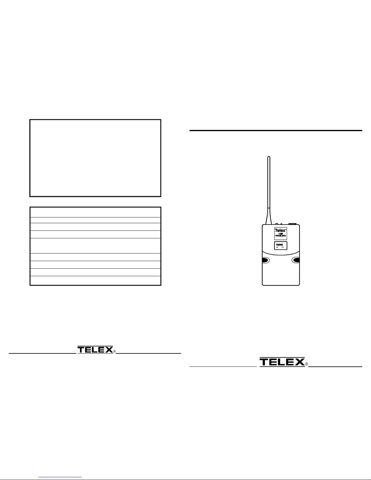
LT-1000
BODY PACK TRANSMITTER
FOR USE WITH
ENG-100
PN 803972 Made in U.S.A. DEC 2003
TELEX COMMUNICATIONS, INC. 12000 Portland Ave. So., Minneapolis, MN 55420, U.S.A.
LT-1000 SPECIFICATIONS
Radiated Output ..................................30 mW Typical
Standard Lavalier Microphone .....ELM-22 Omni-Directional Condenser
TA4F Connector Wiring ................Pin 1: Ground; Pin 2 Mic Input;
Pin3: +5V bias; Pin 4: +5V bias
through a 3k Ω resistor
Audio Gain Adjustment Range .......................40 dB WT-500
Power Requirements.........................9 Volt Alkaline Battery
Battery Life .....................>8 hours with 9-Volt Alkaline Typical
Antenna................................Flexible external 1/4 wave
Dimensions ........................3.8 in. H x 2.38 in. W x 0.92 in. D
96.5 mm H x 60.5 mm W x 23.4 mm D
ACCESSORIES and PARTS
Model No. Order No.
Premium Omnidirectional Lapel Microphone ELM-22 70925006
Unidirectional Lapel Microphone UML21 ULM21
Premium Lapel
Unidirectional Microphone ELM-33 70926001
Presenter's Headworn Microphone HM2 HM2
Singer's Headworn Microphone HM7 HM7
Bodypack Pouch WP-1000 879553
Beltclip Kit WP-1000 879518-1
Page 2
Bodypack Transmitter- LT-1000
1
8
5
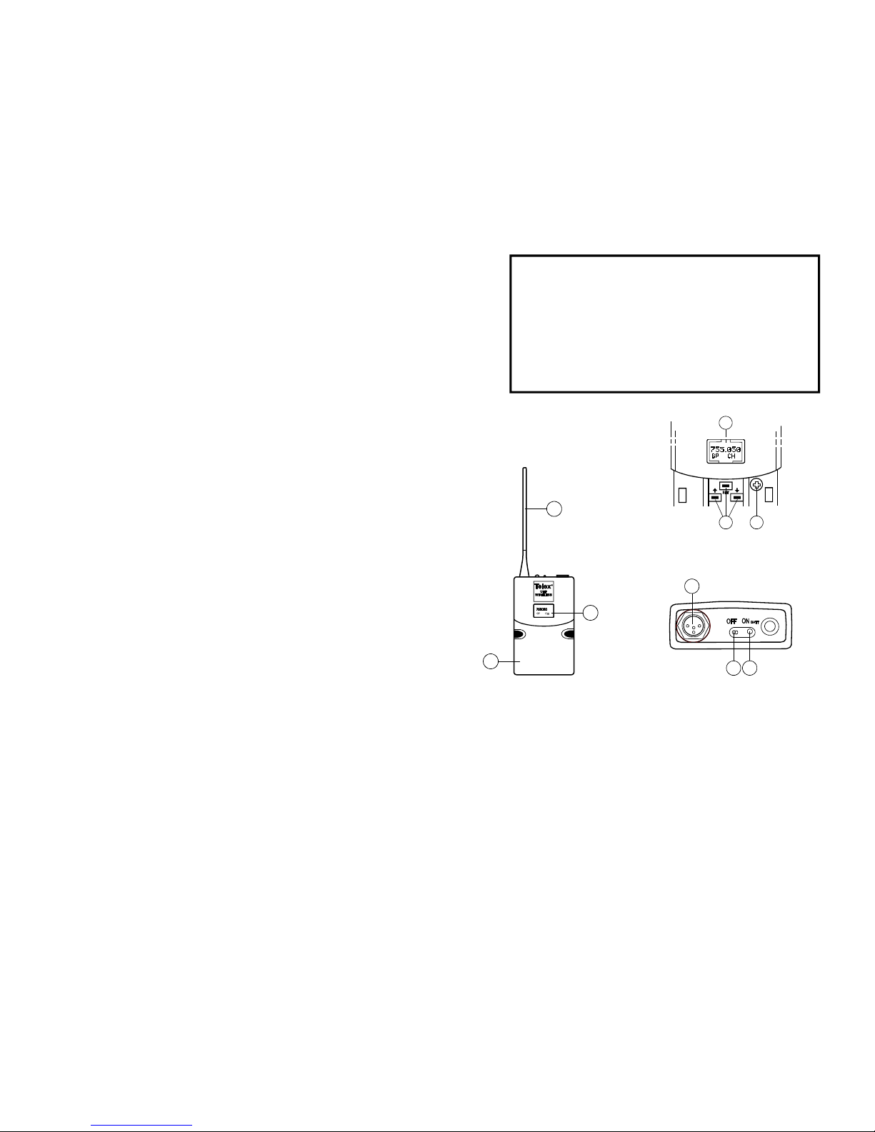
Figure 1
Bodypack Transmitter
6
9
5
4
2
3
Figure 2
Control View
Figure 3
Top View
1.
Insert Battery. Pinch the battery door
tabs inward and pull the door open. Insert
a 9V battery as indicated by the +/- in the
holder.
2. With battery compartment still open, turn
the unit on with Power switch on the top
panel. The battery low LED will light for
a second and the display will show the
Channel numbers.
3.
Change the channel numbers to match
those displayed on the receiver by
pressing SET. The Channel number will
flash and can be changed with the
UP/DOWN keys. Once the desired
Channel number is showing, press SET
and the flashing will stop and the channel
is now set.
4.
Set Key Lock-Out. By pressing and
holding the UP and DOWN arrow keys
together for 3 seconds, the SET key is
disabled. To reactivate the SET key,
simply press and hold the UP and DOWN
keys again for 3 seconds.
5.
Verify reception. With the transmitter
and receiver on with matching Channels,
one of the "Diversity" lights on the ENG
should illuminate. If the ENG does not
show reception, make sure the channels
are matching and refer to the trouble
shooting section.
6.
Attach the Microphone.
Microphone: Plug the microphone cable
into the top panel of the LT-1000. Speak
into the microphone and the "O/M" light
on the ENG should indicate audio signal
presence.
7.
Adjustment of the Transmitter
Audio Gain - (if necessary). The
transmitter audio gain is factory set at
the middle of the range, which should
be suitable for most applications. For
loud or soft speakers/singers, a gain
adjustment may be necessary.
Have the speaker use the microphone in a
normal performance level voice. The O/M
light should just "flicker" on and off. If the
light is on most of the time or not on at all,
adjust the transmitter audio gain.
To adjust the transmitter gain, gently
insert the provided screwdriver (or other
screwdriver) into the adjustment
potentiometer. Gently turn counterclockwise
until the control stops (the microphone
output is at minimum but not off). Slowly
turn the gain control up (clockwise) while
speaking into the microphone until the
O/M light just flickers.
NOTE: Operating with the
transmitter audio gain set as above
will result in the best performance
and highest signal to noise ratio.
Other Screens: Press SET and DOWN
at the same time to display the battery
level. Press SET and DOWN again to
display frequency. Press them one more
time to return to the Channel number.
8.
Power Lock Out - Press and hold SET,
UP, and DOWN at the same time and
hold for 3 seconds to lock the power
switch on. To turn the unit off, place the
power switch in the OFF position and
push SET, UP, or DOWN. To remove the
lock, press SET, UP, and DOWN again at
the same time and hold for 3 seconds. A
one-time only ON-Lock mode can also
be entered by quickly cycling the power
switch three times.
Bodypack Transmitter Setup and Operation
APPROVAL INFORMATION
The Telex Transmitter is Type Accepted under United States Federal
Communications Commission CFR 47, Part 74 and Industry Canada RSS123.
Licensing of Electro-Voice/Telex equipment is the users responsibility and
Licensability depends upon the users classification, users application and
frequency selected. Electro-Voice/Telex strongly urges the user to contact the
appropriate telecommunications authority for any desired clarification.
CAUTION: Any changes or modifications made to the above equipment could void
the users authority to operate the equipment.
1. Antenna - flexible 1/4 wave antenna
2. Power On/Off Switch
3. Battery Low LED Indicator
4. TA4 Audio Connector
5. LCD Display (Channel, Frequency
or Battery Level Indication)
6. Display Control Buttons (Set/Up/Down)
7. Belt Clip (Removable, not shown)
8. 9V Battery Compartment
9. Audio Gain Adjustment
 Loading...