

Page 1
USER INSTRUCTIONS
MODEL LCP-100A LEVEL CONTROL PANEL
FOR KP96/97/98 KEYPANELS WITH KP96-RC REAR CONNECTOR PANELS
AND EKP96/97 EXPANSION PANELS WITH DUAL CONTROL CONNECTORS
®
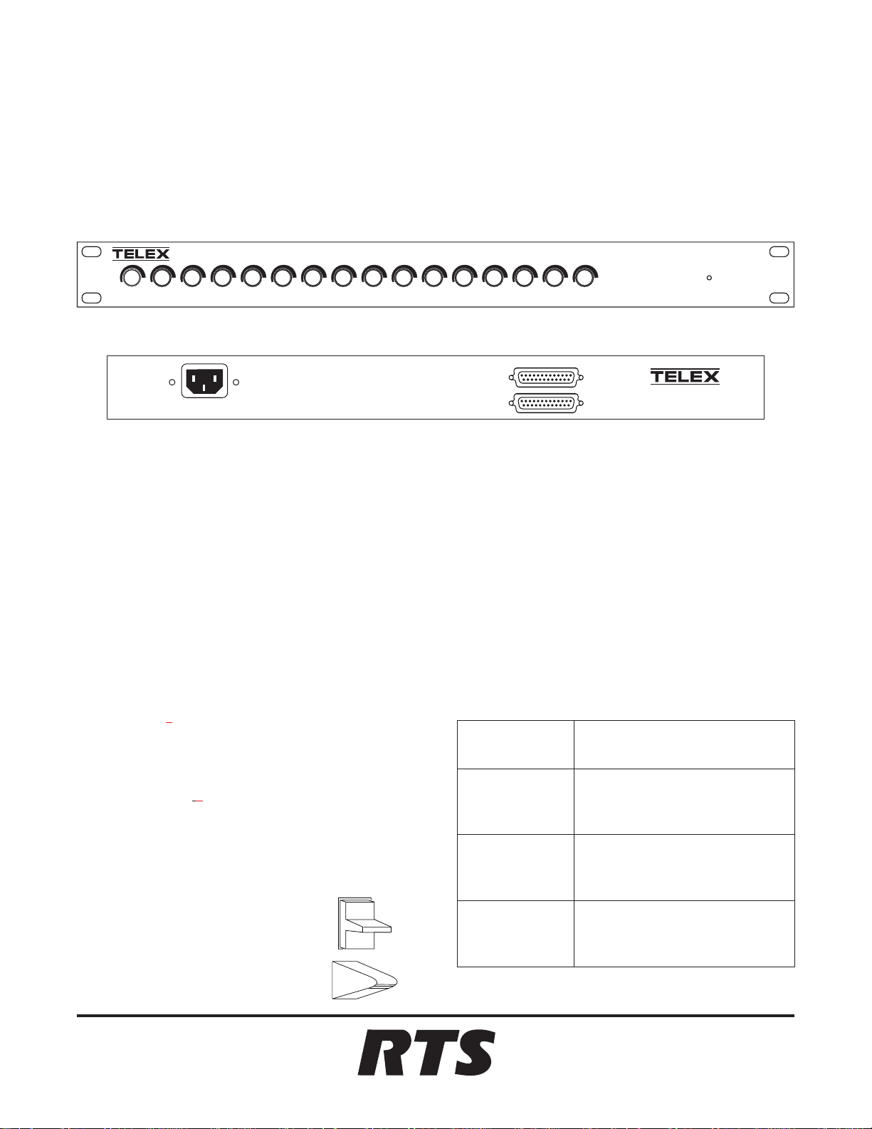
LCP-100A
EXP. DA TAIN
EXP. DA TAOUT
General Description
The LCP-100A Level Control Panel gives keypanel operators direct access to the crosspoint gain adjustment feature
of the intercom system. It lets them adjust the individual
listen levels for 16 keypanel or expansion panel keys.
Upgrade EEPROM
The LCP-100A is compatible with all KP96, KP97, and
KP98-7 Keypanels. However, the supplied keypanel
EEPROM may need to be installed in some cases. Since the
EEPROM is different for each keypanel model, the
LCP-100A is packaged under three different catalog numbers. See Table 1. The following paragraphs summarize the
keypanel model and EEPROM version identification, and
the procedure to replace the EEPROM. Note that the new
EEPROM changes the keypanel DIP switch functions as
summarized on page 2.
Keypanel Model Identification
®
TELEX COMMUNICATIONS,INC.
Minneapolis, MN.
Keypanel EEPROM Version Identification
Keypanels with programming keypad: Tap key sequence CLR-0-8. Then use the scroll up or down key to
locate the version number. It will be something like V82 or
V83G etc.
Note: If you are not able to determine the version with this
key sequence, or if the keypanel does not have a programming keypad, replace the EEPROM.
Table 1. LCP-100A catalog numbers and usage
Catalog Number
(On Box)
9000-7616-100
KP96 Keypanel. Install new
keypanel EEPROM if current
keypanel version is before 8.4G.
Usage
The KP98-7 Keypanel has all pushbutton keys. Identify
KP96 and KP97 Keypanels by the talk key style.
KP96 Keypanels (Carling Lever Keys)
KP97 Keypanels (TMC Lever Keys)
9330-7616-001 Rev A 10/98
9000-7616-110
9000-7616-120
™
KP97 Keypanel. Install new
keypanel EEPROM if current
keypanel version is before 8.4G.
KP98-7 Keypanel. Install new
keypanel EEPROM if current
keypanel version is before 8.3.
Page 2
EEPROM Replacement
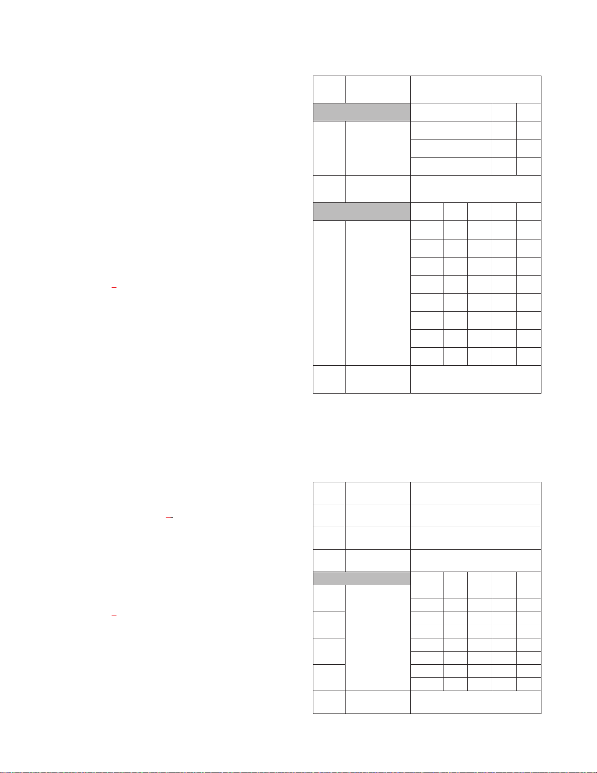
Table 2. KP96/97 DIP Switch Summary
Use normal precautions when handling static-sensitive devices.
1. Unplug the keypanel power cord.
2. Remove the screws from the top cover.
3. Locate the old EEPROM (U305). Observe the orientation of the old EEPROM, then remove it and install the
new EEPROM in the same orientation.
4. Replace the top cover and reconnect power.
KP96/97 Keypanel DIP Switch Functions after
EEPROM Replacement
Refer to Table 2
and the following descriptions.
☞ Important: Any time you change the DIP switch
settings you must turn the power off-then-on to reset.
Combinations of Expansion and Level Control Panels:
Dip switches 1 and 2 select the various allowable combinations of expansion panels and level control panels that
can be connected to the keypanel.
DIP
Switch
1, 2
3 Winking On / Off Open: Winking off
4-7
8 Baud rate select Open: 9600 baud
Description Settings
Combinations SW 1 SW 2
Combinations of
expansion and
level control
panels
Logical keypanel
address select.
0 EKP’s, 0 or 1 LCP X Open
1 EKP, 0 to 2 LCP’s Open Close
2 EKP’s, 0 to 3 LCP’s Close Close
Closed: Winking on
Address SW 4 SW 5 SW 6 SW 7
1 Close Open Open Open
2 Open Close Open Open
3 Close Close Open Open
4 Open Open Close Open
5 Close Open Close Open
6 Open Close Close Open
7 Close Close Close Open
8 Open Open Open Close
Closed: 76.8 kbaud (DO NOT USE!)
(X=Don’t care)
Winking On / Off: DIP switch 3 turns the winking feature
on or off. When winking is on, the LED in each listen key
will wink when the talk key directly beneath it is on. This
provides a visual reminder of any active talk paths. For
some people, this may be distracting and the feature may
be turned off.
Keypanel Address: DIP switches 4-7 set the keypanel
address as before. See Table 4
for address numbers.
Keypanel Baud Rate: Dip switch 8 sets the baud rate as
before.
KP98-7 Keypanel DIP Switch Functions after
EEPROM Replacement
Refer to Table 3
and the following descriptions.
☞ Important: Any time you change the DIP switch
settings you must turn the power off-then-on to reset.
Talk Key Row Selection: You can select whether you
want the talk keys to use the top row (above the displays)
or the bottom row. See DIP switch 1 settings.
Table 3. KP98-7 DIP Switch Summary
DIP
Switch
1 Talk key row
2 Expansion Panel
3 LCP select Open: No LCP connected
4
5 3 Close Close Open Open
6 5 Close Open Close Open
7 7 Close Close Close Open
8 Baud rate select Open: 9600 baud
Description Settings
select
In-use Indication
Logical keypanel
address select.
Open: Use bottom row
Closed: Use top row
Open: Flash
Closed: No flash
Closed: LCP connected
Address Sw 4 Sw 5 Sw 6 Sw 7
1 Close Open Open Open
2 Open Close Open Open
4 Open Open Close Open
6 Open Close Close Open
8 Open Open Open Close
Closed: 76.8 kbaud (DO NOT USE!)
2
Page 3

Expansion Panel In-use Indication for IFB and ISO:
The KP98-7 provides a flashing display indication when
an IFB or ISO is in-use by another keypanel. Generally,
the keypanel operator can distinguish this from an incoming call for two reasons: first, the flashing indication is
slower than an incoming call indication; second, an IFB or
ISO will generally have a distinctive name, and since calls
are not normally received from an IFB or ISO, the
keypanel operator is able to conclude that the flashing indication is not an incoming call.
EKP98-0 expansion panels connected to the KP98-7 are a
different matter, however, since they use illuminated buttons without alphanumeric displays and cannot display
names. In this case the keypanel operator can only distinguish between an in-use indication and an incoming call
indication by the speed of the button flash. If this creates
confusion, disable the flashing in-use indication by setting
DIP switch 2 to the “closed” position.
LCP Selection: If a level controlpanelwill be connected for
use with the KP98-7, set DIP switch 3 to the “Closed” position. Otherwise, leave this switch in the “Open” position.
Keypanel Address: DIP switches 4-7 set the keypanel address as before. See Table 4 for address numbers.
Operation Notes
KP96/97 Keypanels
Keypanel operation is described in the KP96/97 Operating
Instructions Manual. Note that the MVOL feature is no
longer applicable with the updated firmware. To adjust the
listen level for any keypanel key, rotate the corresponding
control on the LCP-100A.
KP98-7 Keypanel
Keypanel operation is described in the KP98-7 Operating
Instructions Manual. Note that the MVOL feature is no
longer applicable with the updated firmware. To adjust the
listen level for any keypanel key, rotate the corresponding
control on the LCP-100A.
The EKP98-0 does not have listen keys, but only has talk
keys. Therefore, it is not possible to manually activate the
listen path corresponding to any talk key. Consequently,
you should assign either the auto-listen or auto-reciprocal
special function to all listen keys. Auto-listen will force
the listen path to activate whenever the corresponding talk
key is pressed. Auto-reciprocal will force the listen path to
always be on.
Baud Rate: SW1-8 selects the baud rate as before.
Mounting
For ease of use, we recommend mounting each LCP-100A
directly above or below the keypanel or expansion panel
that it will be used with. The LCP-100A knobs do line up
with the keys on KP96/97 Keypanels and EKP96/97 Expansion Panels. When using the LCP-100A with a KP98-7, you
may wish to label the knobs.
Connections
KP96/97 Keypanels
Typical connections for a KP97/96 keypanel are shown in
Figure 1. A maximum of two expansion panels and three
level control panels may be connected.
KP98-7 Keypanel
Typical connections for the KP98-7 are shown in Figure 2
A maximum of one EKP98-0 and one LCP-100A may be
connected. The LCP-100A can only be used to adjust levels for the KP98-7.
Once you have assigned the EKP98-0 keys, you can adjust
the listen levels using the crosspoint gain feature of
ADAMedit (or ZEUSedit).
.
3
Page 4

Keypanel with LCP-100A Level Control Panel Only
KEYPANEL
EXPANSION
EXP.DATA IN
EXP.DATA OUT
LCP-100A
Keypanel with Expansion Panels only.Note: Do not exceed 2 expansion panels.
KEYPANEL
EXPANSION
EXPANSION PANEL EXPANSION PANEL
CONTROL CONTROL
Keypanel with Expansion Panels and LCP-100A Level Control Panels.
Panels after the Expansion Panels.
KEYPANEL
EXPANSION
Note: Do not exceed 2 expansion panels and 3 level control panels.
EXPANSION PANEL 1
CONTROL
Always connect the Level Control
EXPANSION PANEL 2
CONTROL
LCP-100A
Adjusts Keypanel Levels
EXP.DATA IN
EXP.DATA OUT
Adjusts Expansion Panel 1 Levels
EXP.DATA IN EXP.DATA IN
EXP.DATA OUT EXP.DATA OUT
LCP-100A
Adjusts Expansion Panel 2 Levels
LCP-100A
Figure 1. Typical Interconnections when using a KP96/97 Keypanel. A maximum of two expansion panels
and three level control panels may be connected.
4
Page 5

KP98-7 Keypanel with LCP-100A Level Control Panel Only
KP98-7
EXPANSION
EXP.DATA IN
EXP.DATA OUT
LCP-100A
KP98-7 Keypanel with EKP98-0 Expansion Panel Only
KP98-7
EXPANSION
EKP98-0
CONTROL
KP98-7 Keypanel with LCP-100A Level Control Panel and EKP98-0 Expansion Panel
(The LCP-100A adjusts levels only for the KP98-7 Keypanel.)
KP98-7
LCP-100A
EKP98-0
EXPANSION
EXP.DATA IN
EXP.DATA OUT
CONTROL
Figure 2. Typical Interconnections when using a KP98-7 Keypanel. A maximum of one EKP98-0 and one
LCP-100A may be connected. The LCP-100A can only be used to adjust levels for the KP98-7.
5
Page 6

Table 4. Address Numbers for Intercom Ports
Address
Numbers
1 1 9 17 25 33 41 49 57 65 73 81 89 97 105 113 121 129 137 145 153 161 169 177 185 193
2 2 10 18 26 34 42 50 58 66 74 82 90 98 106 114 122 130 138 146 154 162 170 178 186 194
3 3 11 19 27 35 43 51 59 67 75 83 91 99 107 115 123 131 139 147 155 163 171 179 187 195
4 4 12 20 28 36 44 52 60 68 76 84 92 100 108 116 124 132 140 148 156 164 172 180 188 196
5 5 13 21 29 37 45 53 61 69 77 85 93 101 109 117 125 133 141 149 157 165 173 181 189 197
6 6 14 22 30 38 46 54 62 70 78 86 94 102 110 118 126 134 142 150 158 166 174 182 190 198
7 7 15 23 31 39 47 55 63 71 79 87 95 103 111 119 127 135 143 151 159 167 175 183 191 199
8 8 16 24 32 40 48 56 64 72 80 88 96 104 112 120 128 136 144 152 160 168 176 184 192 200
1 201 209 217 225 233 241 249 257 265 273 281 289 297 305 313 321 329 337 345 353 361 369 377 385 393
2 202 210 218 226 234 242 250 258 266 274 282 290 298 306 314 322 330 338 346 354 362 370 378 386 394
3 203 211 219 227 235 243 251 259 267 275 283 291 299 307 315 323 331 339 347 355 363 371 379 387 395
4 204 212 220 228 236 244 252 260 268 276 284 292 300 308 316 324 332 340 348 356 364 372 380 388 396
6
5 205 213 221 229 237 245 253 261 269 277 285 293 301 309 317 325 333 341 349 357 365 373 381 389 397
6 206 214 222 230 238 246 254 262 270 278 286 294 302 310 318 326 334 342 350 358 366 374 382 390 398
7 207 215 223 231 239 247 255 263 271 279 287 295 303 311 319 327 335 343 351 359 367 375 383 391 399
8 208 216 224 232 240 248 256 264 272 280 288 296 304 312 320 328 336 344 352 360 368 376 384 392 400
1 401 409 417 425 433 441 449 457 465 473 481 489 497 505 513 521 529 537 545 553 561 569 577 585 593
2 402 410 418 426 434 442 450 458 466 474 482 490 498 506 514 522 530 538 546 554 562 570 578 586 594
3 403 411 419 427 435 443 451 459 467 475 483 491 499 507 515 523 531 539 547 555 563 571 579 587 595
4 404 412 420 428 436 444 452 460 468 476 484 492 500 508 516 524 532 540 548 556 564 572 580 588 596
5 405 413 421 429 437 445 453 461 469 477 485 493 501 509 517 525 533 541 549 557 565 573 581 589 597
6 406 414 422 430 438 446 454 462 470 478 486 494 502 510 518 526 534 542 550 558 566 574 582 590 598
7 407 415 423 431 439 447 455 463 471 479 487 495 503 511 519 527 535 543 551 559 567 575 583 591 599
8 408 416 424 432 440 448 456 464 472 480 488 496 504 512 520 528 536 544 552 560 568 576 584 592 600
Intercom Port Numbers
1 601 609 617 625 633 641 649 657 665 673 681 689 697 705 713 721 729 737 745 753 761 769 777 785 793
2 602 610 618 626 634 642 650 658 666 674 682 690 698 706 714 722 730 738 746 754 762 770 778 786 794
3 603 611 619 627 635 643 651 659 667 675 683 691 699 707 715 723 731 739 747 755 763 771 779 787 795
4 604 612 620 628 636 644 652 660 668 676 684 692 700 708 716 724 732 740 748 756 764 772 780 788 796
5 605 613 621 629 637 645 653 661 669 677 685 693 701 709 717 725 733 741 749 757 765 773 781 789 797
6 606 614 622 630 638 646 654 662 670 678 686 694 702 710 718 726 734 742 750 758 766 774 782 790 798
7 607 615 623 631 639 647 655 663 671 679 687 695 703 711 719 727 735 743 751 759 767 775 783 791 799
8 608 616 624 632 640 648 656 664 672 680 688 696 704 712 720 728 736 744 752 760 768 776 784 792 800
 Loading...