

Page 1
KP-812 Keypanel
Desktop with Handset, Desktop,
Rack Mount and Lever Key
User Manual
9350-7761-000 REV M 6/2005
Page 2

PROPRIETARY NOTICE
The product information and design disclosed herein
were originated by and are the property of Telex
Communications, Inc. Telex reserves all patent,
proprietary design, manufacturing, reproduction, use
and sales rights thereto, and to any article disclosed
therein, except to the extent rights are expressly
granted to others.
COPYRIGHT NOTICE
RETURN SHIPPING INSTRUCTIONS
PROCEDURE FOR RETURNS
If a repair is necessary, contact the dealer where this
unit was purchased.
If repair through the dealer is not possible, obtain a
RETURN AUTHORIZATION from:
Customer Service Department
Telex Communications, Inc.
Telephone: (800) 382-3497
Fax: (800)323-0498
Copyright 2005 by Telex Communications, Inc. All
rights reserved. Reproduction, in whole or in part,
without prior written permission from Telex is prohibited.
UNPACKING AND INSPECTION
Immediately upon receipt of the equipment, inspect
the shipping container and contents carefully for any
discrepancies or damage. Should there be any, notify
the freight company and the dealer at once.
CUSTOMER SUPPORT
Technical questions should be directed to:
Customer Service Department
RTS/Telex
12000 Portland Avenue South
Burnsville, MN 55337 USA
Telephone: (800) 392-3497
Fax: (800) 323-0498
DO NOT RETURN ANY EQUIPMENT DIRECTLY TO
THE FACTORY WITHOUT FIRST OBTAINING A
RETURN AUTHORIZATION.
Be prepared to provide the company name, address,
phone number, a person to contact regarding the
repair, the type and quantity of equipment, a description of the problem and the serial number(s).
SHIPPING TO MANUFACTURER FOR
REPAIR OR ADJUSTMENT
All shipments of RTS products should be made via
United Parcel Service or the best available shipper,
prepaid. The equipment should be shipped in the
original packing carton; if that is not available, use
any suitable container that is rigid and of adequate
size. If a substitute container is used, the equipment
should be wrapped in paper and surrounded with at
least four inches of excelsior or similar shock-absorbing material. All shipments must be sent to the
following address and must include the Return
Authorization
Factory Service Department
Telex Communications, Inc.
1930 West 1st Street
Blue Earth, MN 56013 U.S.A
Attn: Service
Upon completion of any repair the equipment will be
returned via United Parcel Service or specified
shipper collect.
2
KP-812 Keypanels User Manual
Page 3

Table of Contents
Chapter 1 ............................................................................................................................. 7
Introduction ................................................................................................................................................. 7
General Description .................................................................................................................................... 7
Features ...................................................................................................................................................... 8
Options ....................................................................................................................................................... 8
Connections and Controls ........................................................................................................................... 9
KP-812 Keypanel with Handset ............................................................................................................ 9
KP-812 Keypanel - Desktop................................................................................................................ 10
KP-812 Keypanel - Rack Mount .......................................................................................................... 11
Controls Descriptions ......................................................................................................................... 12
Specifications ............................................................................................................................................14
Chapter 2 ............................................................................................................................ 19
Installation ................................................................................................................................................. 19
Connections .............................................................................................................................................. 21
Headset Connector .............................................................................................................................22
Panel Microphone Connector.............................................................................................................. 22
Aux In ................................................................................................................................................. 22
Microphone Preamplifier ..................................................................................................................... 22
External Headset, Speaker Output, and Footswitch Input ................................................................... 22
GPIO Relay 1 & 2 (A&B) .................................................................................................................... 22
Coaxial Connection (CS-200 Coaxial System Interface) ..................................................................... 22
Replace the Flash Cards to Upgrade the Firmware Version to 2.0 or later ................................... 23
Cable the CSI-200, KP-812 and Frame ........................................................................................ 23
Chapter 3 ............................................................................................................................ 25
Basic Operation......................................................................................................................................... 25
Selecting Headset or Speaker ............................................................................................................ 25
Listen Volume Adjustments ................................................................................................................. 25
Listen Source Selection LED .............................................................................................................. 26
Intercom Keys and Displays ................................................................................................................ 27
Intercom Key Operation ............................................................................................................................ 29
Basic Intercom Key Operation ................................................................................................................... 29
Operation of Intercom Keys with Auto Functions ................................................................................. 29
Operation of Intercom Keys with Options ............................................................................................ 30
Operation of Intercom Talk Keys with the Speaker DIM Setting .......................................................... 30
Operation of Intercom Keys assigned to TIF Ports .............................................................................. 30
Muting the Microphone ....................................................................................................................... 30
Call Waiting Operation ........................................................................................................................ 30
Addressing.......................................................................................................................................... 31
KP-812 Keypanels User Manual
3
Page 4

Chapter 4 ............................................................................................................................ 33
Telephone Operation ................................................................................................................................. 33
Receiving a Phone Call....................................................................................................................... 33
Dialing and Hanging Up Using the KP-812 Keypanel Dialing Menu ....................................................33
Manual Dialing .................................................................................................................................... 33
Redial ................................................................................................................................................. 34
Autodial ............................................................................................................................................... 34
Chapter 5 ............................................................................................................................ 37
KP-812 Keypanel Menu System................................................................................................................ 37
Menu System, Menu Access .............................................................................................................. 37
Menu System, Display Menu .............................................................................................................. 37
Display Menu, Assign Type ........................................................................................................... 37
Display Menu, Chan ON ............................................................................................................... 38
Display Menu, Key Groups ...........................................................................................................38
Display Menu, Key List ................................................................................................................. 38
Display Menu, Level 2 .................................................................................................................. 38
Display Menu, Listen .................................................................................................................... 38
Display Menu, Matrix .................................................................................................................... 38
Display Menu, Panel ID ................................................................................................................ 38
Display Menu, Version .................................................................................................................. 38
Menu System, Key Assign Menu ........................................................................................................ 39
General Procedure to use the Key Assign Menu ..........................................................................39
Key Assign, Pt-to-Pt ..................................................................................................................... 40
Key Assign Menu, Party Line ........................................................................................................ 41
Key Assign Menu, IFB .................................................................................................................. 41
Key Assign Menu, Spcl List .......................................................................................................... 41
Key Assign Menu, Sys Relay........................................................................................................ 41
Key Assign Menu, Camera ISO .................................................................................................... 41
Key Assign Menu, UPL Resrc ......................................................................................................41
Key Assign Menu, Quick Assign: ..................................................................................................41
Key Assign Menu, Reset Vols ....................................................................................................... 42
Menus................................................................................................................................................. 43
Menu, Auto Dial ............................................................................................................................ 43
Menu, Key Option Chime.............................................................................................................. 43
Removing the chime option from a key......................................................................................... 43
Menu, Key Option, Key Groups ....................................................................................................44
Clearing a Key Group ................................................................................................................... 44
Menu, Key Option, Solo ................................................................................................................ 45
Removing the Solo Key Option ..................................................................................................... 45
Menu, Key Option, Exclusive ........................................................................................................ 45
Removing the Exclusive Key Option ............................................................................................. 45
Service Menu ...................................................................................................................................... 46
Service Menu, Aux Inputs ............................................................................................................ 46
Service Menu, Dim .......................................................................................................................46
Service Menu, LCD Bright ............................................................................................................ 46
Service Menu, DSP Func ............................................................................................................. 47
Service Menu, Handset ................................................................................................................ 49
Service Menu, LCP-16 ................................................................................................................. 49
Service Menu, Local GPIO ...........................................................................................................50
Assigning an Input to Activate a Key Group .................................................................................. 50
Removing an Input Assignment ....................................................................................................51
Adding or Removing a GPI Ouput Key Assignment ...................................................................... 51
Service Menu, Matrix Out ............................................................................................................. 52
Service Menu, Mic Select .............................................................................................................52
Service Menu, Min Volume ........................................................................................................... 52
4
KP-812 Keypanels User Manual
Page 5

Service Menu, Speaker ................................................................................................................ 53
Service Menu, Mod Assign ........................................................................................................... 53
Service Menu, Output Level ......................................................................................................... 54
Service Menu, Preamp Out .......................................................................................................... 54
Service Menu, Reset Cfg ............................................................................................................. 54
Service Menu, Save Cfg............................................................................................................... 54
Service Menu, Sidetone ............................................................................................................... 54
Service Menu, Test Panel ............................................................................................................. 55
Service Menu, Tone Gen .............................................................................................................. 55
Service Menu, Tally Duration ........................................................................................................ 55
Special Functions ............................................................................................................................... 56
Quick Assign....................................................................................................................................... 56
User Assignable Key ........................................................................................................................... 56
Special Functions ............................................................................................................................... 56
Chapter 6 ............................................................................................................................ 57
KP-812 Keypanel Firmware Download ...................................................................................................... 57
Download Keypanel Firmware through AZedit........................................................................................... 57
Chapter 7 ............................................................................................................................ 61
KP-812 Keypanel Menu System Quick Reference .................................................................................... 61
Menu Access ............................................................................................................................................ 61
Menu List .................................................................................................................................................. 61
Glossary .............................................................................................................................. 63
Addendum ........................................................................................................................... 69
KP-812 Keypanels User Manual
5
Page 6

6
KP-812 Keypanels User Manual
Page 7

Chapter
1
Introduction
General Description
The RTS ™ KP-812 keypanel fits in a standard 19” rack and is one rack space high. It has 12 keys (one listen
button and one talk button make up a key): 10 keys are for intercom talk and listen, two keys are for call
waiting response.
In addition, there are two encoders. One encoder is used for headset, microphone, auxilliary input, and matrix
in volume adjustment. The other encoder knob is used for menu selection. The KP-812 keypanel has a standard numerical keypad with four extra keys: Mic Mute, User Assignable, Page Up, and Page Down.
The KP-812 keypanels add significant new features such as digital signal processing.
KP-812 keypanels also offer a custom design LCD display with support for 16x16 Kanji, Katakana, Hiragana,
and English characters.
The KP-812 keypanels are made of pressed aluminum / metal and feature state of the art audio processors
and drivers. There are three different models of keypanel to choose between - Desktop, Desktop with Handset
and Rackmount.
KP-812 Keypanels User Manual
7
Page 8

Features
•
Talk / Listen Configuration
both latching (hands-free) and momentary (push-to-talk) operation. Plus an extensive scrollable menu
system (accessed using an encoder). Menus include helpful prompts to walk the user through setup.
•
Call Waiting Window
the 12th key is used for menu displays. The CWW is configured through the menu. The user has three
assignable options from the menu, as follows:
1) No CWW
2) One CWW (12th key only)
3) Two CWW (11th and 12th key)
•
Character Display
Each LCD will show two rows of 16 characters for a total of 32 characters. Each display area shows eightcharacter alphas per key (Talk/Listen).
•
Hands-Free Button (Handset Version Only)
button. When this button is active, the user is able to talk through a gooseneck mic and listen through the
front speaker.
: The LCD display is custom designed to show 16x16 size Japanese or Kanji characters.
Note: The KP-812 Keypanels have four keys per display area.
: 12 keys, with 10 keys available for full talk/listen configuration. Keys support
: The 11th and 12th display positions are used as a call waiting windows (CWW), while
: The front panel of the handset version has a hands-free
•
Connections
the matrix connection. On the rack mount model only, there is one RJ-12 connector for Expansion Panels
and one RJ-12 connector for LCP. There are two mechanical pots for Mic level control, one for headset mic
and one for panel mic gain.
Note: Only one Matrix connection can be used at a time.
•
Firmware
through AZedit application to the keypanels.
•
Configuration
(sending and receiving digital audio from the matrix) or as an analog key panel. Digital operation is used
when coaxial cables are used and for future technology enhancements.
•
Remote Applications
mounted separately and connected to the keypanel using up to a maximum of 50 feet of cable.
•
Digital Signal Processing (DSP)
metering, and filtering capabilities.
: The back of each key panel has one DB-9 connector, one RJ-12 connector, and one BNC for
: Every keypanel has an in-system downloadable firmware feature, where firmware is downloaded
: With the appropriate configuration, the KP-812 keypanel can be used as a digital keypanel
: The KP-812 keypanel can be used in remote applications. The front panel can be
: Improves microphone voice activation and limiting. Adds new mixing,
Options
EKP-816: Provides additional 12 or 16 intercom keys.
LCP-12 or 16: Provides easy adjustment of point to point and party line listen levels for individual
intercom keys. One LCP-12 or 16 controls volumes for one row of keys.
8
KP-812 Keypanels User Manual
Page 9
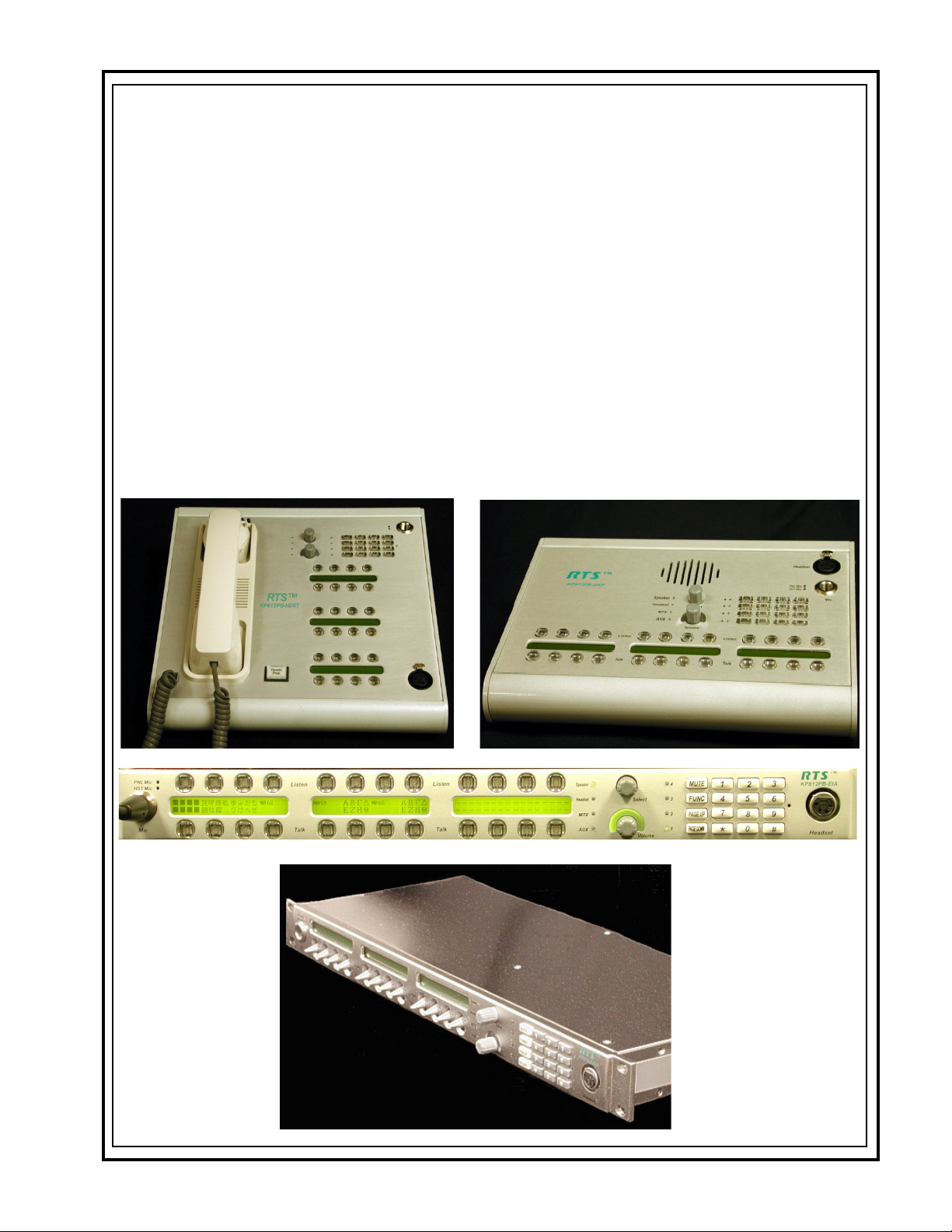
Connections and Controls
TM
KP-812 Keypanel with Handset
Front
Speaker
1
Headset
2
MTX IN
3
AUX IN
4
25
KP812PB-HND
23
24
Back
28
HEADSET
H-MIC
G-MIC
26
FOOT SW/SPEAKER
27
29
FRAME
30
31
9
4
11
5
3
12
Select
6
2
13
7
1
14
8
Volume
10
MIC OUT MIC IN
32
FRONT
1. Speaker LED
15
PNLMic
HSTMic
19
Listen
20
21
Talk
17
16
Mic
18
}
2. Headset LED
3. Matrix LED
4. AUX In LED
5. Page 4 LED
6. Page 3 LED
7. Page 2 LED
8. Page 1 LED
9. Select / Menu Encoder
Listen
10. Volume Control
11. Mic Mute
Talk
Listen
22
Talk
Headset
12. Func
13. Page Up
14. Page Down
15. Panel Mic LED
16. Headset Mic LED
17. Panel Mic Connector
18. Standard Numerical Keypad
19. Listen Keys
20. Display Panel
90-240 V AC
21. Talk Keys
22. Headset Connector
23. Hands-Free Switch
24. Handset RJ-11 Connector
25. Handset/Speaker
AUX IN
33
COAX
34
35
36
BACK
Figure 1. KP-812 Keypanel - Handset Model
KP-812 Keypanels User Manual
26. Headset Mic Gain
27. Mic MicGain
28. External Headset Connector
29. Speaker / Footswitch Connection
30. DB-9 Connection for Matrix(frame)
31. RJ-12 Connection for Matrix(frame)
32. MIC Out
33. MIC In
34. AUX In
35. Coax Connection
36. AC
9
Page 10
KP-812 Keypanel - Desktop
FRONT
Front
1. Speaker
2. Select / Menu Encoder
3. Volume Control
4. Headset Connector
4
1
5
6
8
9
10
11
3
12
16
13
2
17
14
18
15
19
7
20
21
22
23
5. Panel Mic LED
6. Headset Mic LED
7. Panel Mic Connector
8. Speaker LED
9. Headset LED
10. Matrix LED
11. Aux In LED
12. Page 4 LED
13. Page 3 LED
14. Page 2 LED
15. Page 1 LED
16. Mic Mute
17. Func
18. Page Up
19. Page Down
20. Standard Numerical Keypad
Back
21. Listen Keys
22. Display Panel
23. Talk Keys
28
BACK
24
25
26
Figure 2. KP-812 Keypanel - Desktop Model
27
29
30
31
32 33
24. Headset Mic Gain
25. Panel Mic Gain
26. Speaker / Footswitch
34
Connection
27. DB-9 Connection for Matrix
28. External Headset Connector
29. RJ-12 Connection for Matrix
30. MIC Out
31. MIC In
32. AUX In
33. Coaxial Connection
34. AC
10
KP-812 Keypanels User Manual
Page 11
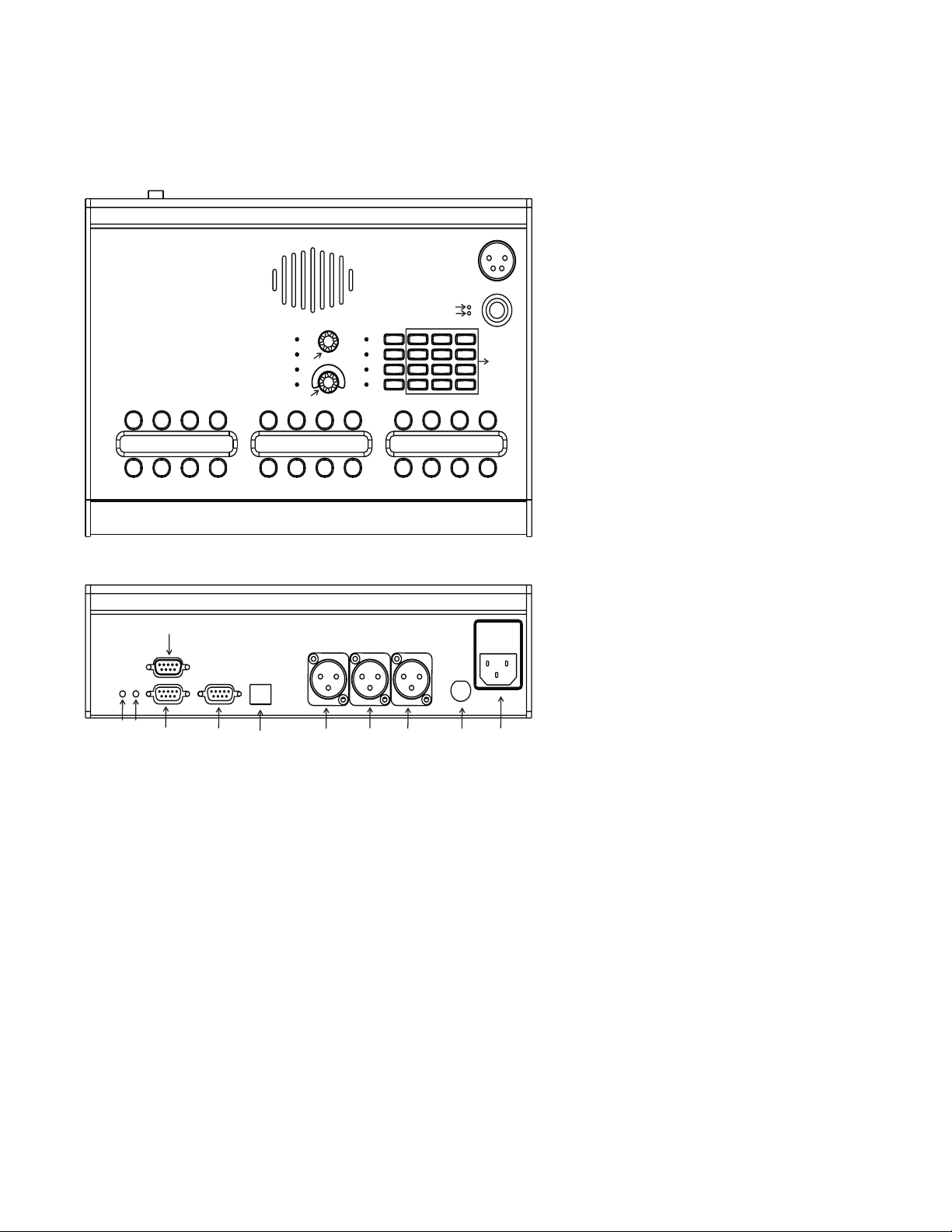
KP-812 Keypanel - Rack Mount
1
2
PNL Mic
HST Mic
Mic
3
5
90-240 V AC
23 24 25 26
Figure 3. KP-812 Keypanel - Rackmount Model
4
}
}
6
MIC OUT MIC IN SPK MON
Listen
Talk
AUX IN
Front
15
Listen
Talk
Back
30
HEADSET
H-MIC G-MIC
FOOT SW/SPEAKER
27
28 29
31
Speaker
7
Headset
8
MTX
9
AUX
10
16
FRAME
EXP
32 33 34
11
Select
12
13
14
Volume
LCP OPT. 1&2
35
4
17
3
18
2
19
1
20
}
36
RELAY 1&2A RELAY 1&2 B
37
21
38
OPT. 3&4 COAX
39 40
KP812PB-EIA
Headset
TM
22
FRONT
1. Panel Mic LED
2. Headset Mic LED
3. Panel Mic Connector
4. Listen Keys
5. Panel Display
6. Talk Keys
7. Speaker LED
8. Headset LED
9. Matrix LED
10. AUX LED
11. Page 4 LED
12. Page 3 LED
13. Page 2 LED
14. Page 1 LED
15. Select / Menu Encoder
16. Volume Control
17. Mic Mute
18. Func
19. Page Up
20. Page Down
21. Standard Numerical Keypad
22. Headset Connector
BACK
23. AC
24. MIC Out
25. MIC In
26. Speaker /Monitor
27. AUX In
28. Headset Gain
29. Mic Gain
30. External Headset Connector
31. Speaker / Footswitch Connection
32. DB-9 Connection for Matrix
33. RJ-11 Matrix Connection
34. RJ-45 EXP Connection
35. RJ-45 LCP Connection
36. Relay 1&2A
37. Opto-Isolate Input 1&2
Open Collector 1&2
38. Relay 1&2B
39. Opto-Isolate Input 3&4
Open Collector 3&4
40. Coaxial Connection
KP-812 Keypanels User Manual
11
Page 12

Controls Descriptions
SPEAKER LED: Indicates the user can adjust the Speaker levels.
HEADSET LED: Indicates the user can adjust the Headset levels.
MATRIX IN LED: Indicates the user can adjust the audio levels from the Matrix to the keypanel.
AUX IN LED: Indicates the user can adjust the audio levels from the Aux In to the keypanel.
PAGE 4 LED: When the Page 4 LED is lit, this indicates that setup page four is assigned to the main
panel.
PAGE 3 LED: When the Page 3 LED is lit, this indicates that setup page three is assigned to the
main panel.
PAGE 2 LED: When the Page 2 LED is lit, this indicates that setup page two is assigned to the main
panel.
PAGE 1 LED: When the Page 1 LED is lit, this indicates that setup page one is assigned to the main
panel.
MENU ENCODER: The menu encoder knob turns clockwise and counterclockwise to scroll through menu
options. To select an option, tap the encoder key once. To go back one step, doubletap the encoder knob. Press and hold for one second to exit.
VOLUME CONTROL: The volume control knob controls the volume of the selected source or destination
as indicated by the lit LED.
MIC MUTE: The Mic Mute button mutes whichever microphone is active so no audio can be
transmitted through the microphone.
FUNC KEY: The Func key is a user assignable key or soft key that can be programmed to perform
an action that is used frequently or is difficult to access, such as a lower level menu
item. It can also be programmed to operate a local GPI output.
PAGE UP AND DOWN: The Page Up button changes that active page assigned to the main panel.
PANEL MIC CONNECTOR: Accepts an electret gooseneck microphone, such as the Telex model MCP-90-XX.
The model MCP-90 series panel mic connector is a 1/4” stereo plug, with a threaded
shaft for easy installation.
PANEL MIC LED: When the Panel Mic LED is lit green, the Panel Mic is active. This is the default
setting for the KP-812 Keypanel.
HEADSET MIC LED: When the Headset Mic LED is lit green, the headset mic is active. This automatically
when a headset is plugged in.
STANDARD NUMERICAL
KEYPAD: Use the Keypad to enter auto dial numbers, as well as dial outside numbers for TIF
operation.
LISTEN BUTTONS: The listen buttons allow the user to listen to audio coming into the keypanel. To listen,
press an upper button. A green LED will light the button.
12
KP-812 Keypanels User Manual
Page 13

DISPLAY PANEL: The 11th and 12th display positions are used as call waiting windows (CWW) and
menu display. The CWW is configured through the menu. The user has three
assignable options from the menu, as follows:
1) No CWW
2) One CWW (12th key only)
3) Two CWW (11th and 12th key)
TALK KEYS: The talk buttons allow the user to talk to other keypanels. To talk, press a lower
button. A red LED will light the button.
HEADSET CONNECTOR The headset connector is a 4-pin XLR connector, which when plugged into the KP812 keypanel, turns the panel mic off and audio is sent to the headset and the
headset mic is activated.
HANDS-FREE SWITCH
(KP-812 KEYPANEL WITH
HANDSET
ONLY) : When hands-free is activated, the panel mic is selected and audio is heard through
the speaker.
HANDSET RJ-45
CONNECTOR
(KP-812 KEYPANEL
HANDSET ONLY) : Connects the handset to the KP-812 keypanel so telephone style operation is avail-
WITH
able.
HANDSET (RECEIVER)
(KP-812 KEYPANEL WITH
HANDSET ONLY) : The handset, or receiver, allows telephone style operation from the KP-812 keypanel.
The listen audio as well as the talk audio are sent through the microphone and
speaker within the handset.
KP-812 Keypanels User Manual
13
Page 14

Specifications
Microphone Preamplifier
Electret Mic Input Level @ 1 kHz -42 dB, 150ohms
Dynamic Mic Input Level @ 1kHz -50 dBm, 150 ohms
Output Level (to matrix) 0 dBu, ± 0.2 dBu
Max Voltage Gain, Mic to Line 70 dB, ± 2 dB
Frequency Response 100 Hz to 10 kHz, ± 2 dB
Limiter 10 dB above nominal
Tone Generator
Output Level (to matrix) 0 dBu ± 2 dBu
Output Frequency 500 Hz
Headphone Amplifier
Maximum Voltage Gain 200 dB
Frequency Response 100 Hz to 10 kHz, ± 2 dB
Headphone Impedance 8 to 600 ohms
Output Power 1 W to 50 ohms
Output Voltage Level 8 volts peak-to-peak (max.)
Sidetone Range 25 dB
Speaker Amplifier and Speaker
Frequency Response 100 Hz to 10 kHz, ± 2 dB
Output Power (per amplifier) 2 watt into 8 ohms
Output Voltage Level 12 volts peak-to-peak (max.)
Volume Control Range 30 dB
Intercom Input/Output
Input Nominal: 0 dBu, Peak +20 dBu max.
Output 0 dBu, ± 2 dBu nominal
External Line Input (Program Input)
Input Level + 8 dBu nominal
General
AC SUPPLY
Internal switching type, 100-240 VAC, 50/60 Hz with universal IEC connector for connection to
various AC main cords.
Environment
Storeage
Operating
: -40°C (-40°F) to 70°C (158°C)
: -20°C (-4°F) to 60°C (140°F)
DIMENSIONS:
Desktop 11.3 (W) x 7.623 (D) x3.1 (H)
Handset 11.3 (W) x 11 (D) x 3.75 (H)
Rackmount 19 (W) x 7.5 (D) x 1.75 (H)
14
Approvals
UL, CSA, VDE, CE
KP-812 Keypanels User Manual
Page 15

Connectors
Panel Microphone Connector
Headset Connector:
Intercom Connectors: Parallel-wired DE9S and RJ-12 Connectors
Type: 3-circuit, 1/4” phone jack with threaded metal bushing, compatible
with RTS MCP-90
Pin Out: Tip : + Audio and DC bias
Ring: Common
Sleeve: Chassis ground
Type: XLR-4 Female
Pin 1 Mic low
Pin 2 Mic high
Pin 3 Headphone low
Pin 4 Headphone high
Type: DE9S
Pin Out: Pin 1 Data +
Pin 2 Data Pin 3 Audio in (from matrix) shield
Pin 4 Audio out (to matrix) +
Pin 5 Audio out (to matrix) Pin 6 Data shield
Pin 7 Audio in (from matrix) Pin 8 Audio in (from matrix) +
Pin 9 Audio out (to matrix) shield
Type: RJ12
Pin Out: Pin 1 Data -
Pin 2 Audio in (from matrix) +
Pin 3 Audio out (to matrix) +
Pin 4 Audio out (to matrix) Pin 5 Audio in (from matrix) Pin 6 Data +
Expansion Connector
Type: RJ45
LCP Connector
Type: RJ45
KP-812 Keypanels User Manual
15
Page 16

GPI Module Connectors (Optional)
Speaker / Monitor Output
Type: 5-pin XLR Male
Pin out: Pin 1 Line Out (GND)
Aux 1 In (Auxiliary Program Input)
Type: 3-pin XLR Female
Pin out: Pin 1 Ground
Note: Balance input, + 8 dBu nominal
Relay 1 & 2 Out
Type: 9-pin male, D-Sub
Pin out Pin 1 NC contact 1
Pin 2 Line Out (+)
Pin 3 Line Out (-)
Pin 4 SPK Out (+)
Pin 5 SPK Out (-)
Pin 2 Input +
Pin 3 Input -
Pin 2 COM contact 1
Pin 3 NO contact 1
Pin 4 NC contact 2
Pin 5 COM contact 2
Pin 6 NO contact 2
Pin 7 +3.3 VDC
Pin 8 Ground
Pin 9 +3.3 VDC
Relay 3 & 4 Out
Type: 9-pin male D-Sub
Pin out: Pin 1 NC contact 3
Pin 2 COM contact 3
Pin 3 NO contact 3
Pin 4 NC contact 4
Pin 5 COM contact 4
Pin 6 NO contact 4
Pin 7 +3.3 VDC
Pin 8 Ground
Pin 9 +3.3 VDC
Note: The relay 1 and 3 contacts are electrically separate, but operate in unison.
The relay 2 and 4 contacts are electrically separate, but operate in unison.
The +3.3 VDC pins are connected internally through 1K resistors to +3.3 VDC
and can source 3 mA. This voltage can be used with the relay contacts to
create an active high output for some devices that require a +3.3 VDC signal
to activate. For example, connecting pin 7 to pin 3 of the Relay 1 & 2 connec
tor will result in +3.3 VDC on pin 2 when the relay is activated.
16
KP-812 Keypanels User Manual
Page 17

Opto 1-2 In (Opto-isolated control inputs) / OC 1-2 (J11)
Type: 9-pin male D-Sub
Pin-out Pin 1 3.3 VDC
Pin 2 Emitter OC 2
Pin 3 Emitter OC 1
Pin 4 Ground
Pin 5 Ground
Pin 6 Collector OC 1
Pin 7 Collector OC 2
Pin 8 Opto-Out 2
Pin 9 Opto-Out 1
Note: A contact closure between any switch input and ground will activate that input.
The switch contact inputs are also connected internally through 1K resistors
to internal +3.3 VDC and can source 3 mA for use with an external transistor
switch circuit.
Opto 3-4 In (Opto-isolated control inputs) / OC 3-4 (J12)
Type: 9-pin male D-Sub
Pin-out: Pin 1 3.3 VDC
Pin 2 Emitter OC 4
Pin 3 Emitter OC 3
Pin 4 Ground
Pin 5 Ground
Pin 6 Collector OC 3
Pin 7 Collector OC 4
Pin 8 Opto-Out 4
Pin 9 Opto-Out 3
Note: A contact closure between any switch input and ground will activate that input.
The switch contact inputs are also connected internally through 1K resistors
to internal +3.3 VDC and can source 3 mA for use with an external transistor
switch circuit.
Headset (External headset connector)
Type: 9-pin male D-Sub
Pin-out Pin 1 Ground
Pin 2 External headset PTT
Pin 3 External headset PTT enable
Pin 4 External headset enable
Pin 5 Balanced dynamic mic input +
Pin 6 Ground
Pin 7 Left Speaker
Pin 8 Right Speaker
Pin 9 Balanced dynamic mic input -
Note: Mic input -50 dBu nominal. Headset out 0.325 watts into 8 ohms.
KP-812 Keypanels User Manual
17
Page 18

Foot Switch / Speaker
Type: 9-pin male D-Sub
Pin-out: Pin 1 Ground
Pin 2 Speaker Plus (+)
Pin 3 Ground
Pin 4 No Connection
Pin 5 Foot Switch
Pin 6 Speaker Minus (-)
Pin 7 No Connection
Pin 8 No Connection
Pin 9 Ground
Note: A switch contact closure from the footswitch input to ground will activate the
footswitch input.
MIC In Unbalanced Panel Microphone Input
Type: 3-pin XLR Female
Pin-out: Pin 1 Ground
Pin 2 DC bias and Audio Plus (+)
Pin 3 Shield (circuit common)
Note: Input level -42.5 dBu nominal.
MIC Out Balanced Microphone Output
Type: 3-pin XLR Male
Pin-out: Pin 1 Shield (circuit common)
Pin 2 Audio output +
Pin 3 Audio output -
Note: Output level 0 dBu nominal (balanced).
18
KP-812 Keypanels User Manual
Page 19

Chapter
Installation
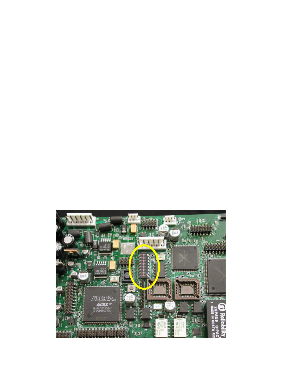
Note: To see where the DIP Switch is on the circuit board, see Figure 4, page 20.
DIP Switch Settings
Switch 1: Latch Enable/Disable
Default Setting: Open (Enable)
Description: An intercom key can always be turned on for momentary conversation by pressing and
holding the key during the conversation. There is also an electronic latching feature that lets you tap
intercom keys to turn them on or off. This permits convenient hands-free conversation. However, it
can also result in a talk circuit being left on unintentionally. For example, A key that talks to a public
address system could be accidentally left on. Or, an IFB key (a type of key assignment often used by
a director or producer to give instructions to a listener, such as a news anchor during a television
broadcast) could accidently be left on, causing confusion for the IFB listener. To prevent such accidents, the latching feature can be turned off.
2
NOTE: DIP Switch 1 disables latching for the entire keypanel. If you just need to disable latching for
selected keys, leave DIP Switch 1 in the “open” position. Then, disable latching for the desired keys
using the “D” check boxes in the Keypanels/Ports setup screen in AZedit.
Switch 2: Enable/ Disable the adjustment of listen volumes.
Default Setting: Open (Enable)
Description: Enables or disables the Key Gain item in the Key Assign menu.
Switch 3: Unused
Default Setting: Open (Enable)
KP-812 Keypanels User Manual
19
Page 20
Switch 4: Call Flash Time-out
Default Setting: Closed (Infinite Tally)
Description: Whenever there is an incoming call and there is a talk key assigned to the caller, the talk
LED next to that key will flash. If this DIP switch is closed the flashing light goes off as the callers talk
key is closed. Otherwise, flash time can be set for 15 second time-out, or until the caller’s talk key is
released. Call Flash Time-out can be set to 5 sec, 10 sec, and 15 sec.
Switch 5: Footswitch Enable/Disable
Default: Open (Disabled)
Description: The optional Connector Module has a footswitch (GRP CALL) input. If the footswitch is
enabled (DIP switch 5 set to the “Closed” position), then keys that are latched on will not activate until
the footswitch is closed. Latched keys are indicated by winking amber talk LEDs (on time less than off
time), and when the footswitch is activated, the LEDs provide normal talk-on indication.
NOTE:
1. If the talk key is held down in the Footswitch mode, the channel will be activated until the user
releases the key. The use of this function does not require the footswitch to be used.
2. If DIP switch 1 is set to the “Closed” position, nothing will latch.
3. Individual keys can be set to non-latching via AZedit. If this is done, the footswitch has no effect on
the keys that have been set to non-latching.
Switch 6: Reserved
Switch 7: Reserved. Must be left in the Open position.
Switch 8: Reserved, Must be left in the Open position.
Figure 4. KP-812 Keypanel board, DIP switch placement.
20
KP-812 Keypanels User Manual
Page 21
Connections
EXP. and LCP. Connectors
Connect from the EXP connector on the back of the KP-812 keypanel to the Expansion 1 connector of
an optional EKP-812 Expansion Panel. Use the interconnect cable supplied with the Expansion Panel.
Note: JP1 must have pins 1 and 2 shorted to use the LCP connection.
Each LCP adjusts the listen levels for up to 16 keypanel keys, and you can connect as many LCP
panels as required to adjust all keys on the KP-812 keypanel and on an EKP-812 Expansion panel.
An interconnect cable is supplied with each LCP. Connect the first LCP to the LCP connector on the
KP-812. Connect the second LCP to the first LCP, and so forth.
Note: When arranging LCP panels in an equipment rack, you should put them directly above or below
the keys they will be used to adjust.
Frame Connector
Use either of the Frame connectors (but not both) to connect to an intercom port of the intercom
system. The intercom port you connect to should agree with the address that you set previously (for
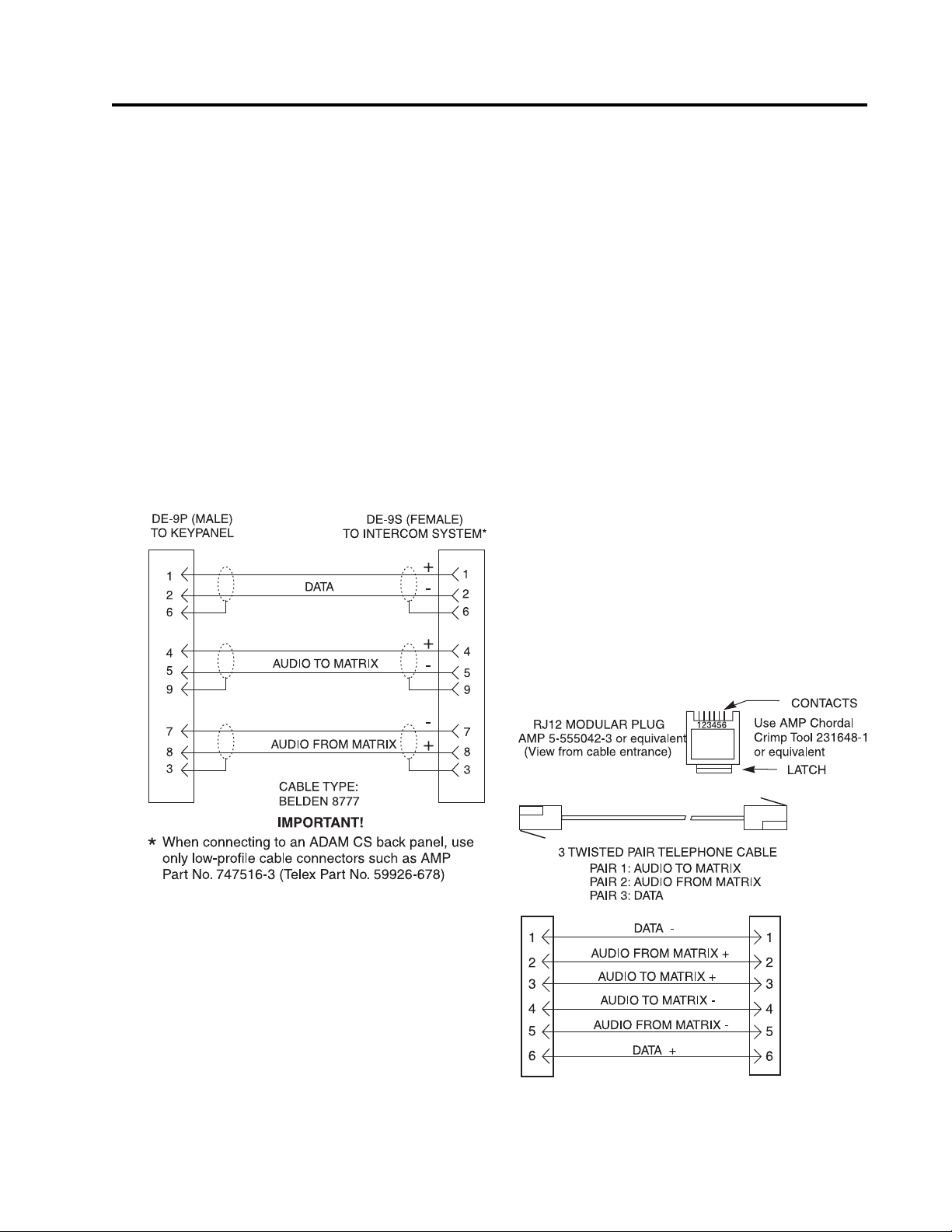
more information on addressing, see page 29). Use the following cable diagrams to help you connect
your system.
Figure 5. DE9S Intercom Cable Wiring
KP-812 Keypanels User Manual
Figure 6. RJ12 Intercom Cable Wiring
21
Page 22

Headset Connector
A duel-sided, mono headset may be connected for use along with or in place of the front panel
speaker and a separate microphone. Headphones may be connected for use with a separate microphone.
Headset Microphone Gain Adjustment
The gain of the headset microphone preamp can be adjusted via the recessed trim pot located on the
back panel (see figures, 1, 2, and 3, on pages 10,11, and 12). Turn the pot clockwise to increase gain
and counterclockwise to decrease gain. The limits are ±20 dB from nominal.
Panel Microphone Connector
A panel microphone may be connected for talking with either the front panel speaker or headphones
used for listening. The connector accepts MCP5, MCP6, or MCP90 Panel Microphones. Insert the
microphone and rotate the entire microphone body several turns to lock in place.
Panel Microphone Gain Adjustment
The gain of the panel microphone preamp can be adjusted via the recessed trim pot located on the
back panel. Turn the pot clockwise to increase gain and counterclockwise to decrease gain. The
limits are ±20 dB from nominal.Aux IN
Aux In
Provides a connector for a line-level audio input (program 1).
Microphone Preamplifier
Provides an unswitched, balanced, microphone preamplifier output.
External Headset, Speaker Output, and Footswitch Input
Provides one DB-9 Headset Connection, one DB-9 Speaker Output/Footswitch Connection.
GPIO
Opto-Isolate Input 1-4 ➝ Four general purpose input lines.
Open Collector 1-4 ➝ Four general purpose output lines.
Relay 1 & 2 (A&B)
Includes two SPDT relay outputs.
Coaxial Connection (CS-100 Coaxial System Interface)
Provides the ability to link the unit to the matrix using a single 75 ohm coaxial cable. The interface
converts all audio and data streams to a single transmission path. Perfect for systems where there
are existing, but unused 75 ohm video cable. Requires CSI-200 interface unit at the intercom matrix
end.
22
KP-812 Keypanels User Manual
Page 23

To convert an existing KP-812 keypanel to use the coaxial connection, do the following:
Requirements:
You will need to upgrade the KP-812(9030-7761-000 [rackmount unit] 9030-7761-001 [desktop unit]) board to
Rev J.
Flash Cards to Upgrade the Firmware Version to 2.0 or later
Flash Chip Old Part Number New Part Number
U21 9015-7761-021
U22 9015-7761-022
1. On the KP-812 board, find U21 and U22 flash cards.
2. Using IC pullers, remove both flash cards.
3. Replace the existing flash cards with the new flash cards (see above for part numbers). Carefully
snap the flash cards in place.
Cable the CSI-200, KP-812 and Frame
1. Connect a DB-9 connection to Frame A or Frame B (depending upon the channel being used) on
the CSI-200.
2. Connect the opposite end of the DB-9 cable to the Frame you want to use (ADAM, ADAM CS,
Zeus, or Cronus).
3. Connect the coaxial calbe (up to 1000 ft) to Coax A or Coax B on the CSI-200 (depending upon
the channel being used).
4. Connect the opposite end of the coaxial cable to the KP-812 COAX connect on the back of the
unit.
5. Using AZedit, add 5 ms to the Panel Poll Delay (Keypanels>Edit button> Advanced).
6. Click Apply.
7. Send changes to the frame.
NOTE: Panel Poll Delay must be set for each CSI-200 connected to the frame.
8. Power ON the CSI-200.
9. Power ON the KP-812.
NOTE: On the CSI-200, the Frame LED is solid green for the channel that is connected and active. The
Transfer (TX) and Receive (RX) LEDs for the specified channel flash rapidly to signify the connection is active. On the KP-812, dashes or panel assignments on the port are displayed in the panel
window.
KP-812 Keypanels User Manual
23
Page 24

24
KP-812 Keypanels User Manual
Page 25

Chapter
3
Basic Operation
Selecting Headset or Speaker
By default, the panel mic is active. When a headset is used via the 4-pin XLR connector on the
keypanel, the Headset Mic LED indicator activates and the headset mic is used.
Listen Volume Adjustments
By default, the Vol. control adjusts the listen volume for the speaker, headset,intercom input, or or
AUX In as indicated by the lit LED. The level of auxiliary program input 1 (if Aux inputs are enabled)
and the level of incoming audio from the intercom matrix can be adjusted. Use the Vol. control to
adjust the listen volume. The Vol. control defaults back to the speaker or headset after about one
minute of inactivity of the control. The minimum volume level for either the keypanel speaker or
headset may be adjusted. See,
Note: You can save the volume adjustments to be the power-up defaults using
Cfg
.
KP-812 Keypanels User Manual
Service Menu, Min Vol
.
Service Menu, Save
25
Page 26

Listen Source Selection LED
There are four LED indicators for Listen Source selection. (Default is speaker LED on, rest of them
off).
Internal Speaker
Headset/Handset
Matrix Audio In
Auxilliary 1 In
On power-up MATRIX IN audio is routed to speaker. This is indicated by the following:
Speaker Selected
Speaker
Headset/Handset
MATRIX IN
AUXIN 1
The audio being heard on the speaker
will be changed through the volume
encoder.
If the encoder were pushed once, it would select between Headset/Handset and Speaker volume. If it
is pushed twice from either headset or speaker it will jump to MATRIX IN, if enabled.
Matrix In Selected
Speaker
Headset/Handset
MATRIX IN
AUXIN 1
The above LEDs indicate that
Level of audio being adjusted
through the encoder is not of speaker
but it is of MATRIX IN.
In order to move between MATRIX IN or AUX IN 1, tap the encoder once is required.
Ta b le
1
Ta bl e
2
Handset/Headset Selected
Speaker
Headset/Handset
MATRIX IN
AUXIN1
The audio being heard on headset is from
MATRIX IN. Audio level on headset will
be changed through the volume encoder.
26
AUX IN Selected
Speaker
Headset/Handset
MATRIX IN
AUXIN 1
The above LEDs indicate that
Level of audio being adjusted
through the encoder is not of speaker
but it is of AUX IN 1.
If the encoder is pushed twice it will go back to the previously selected item in table 1.
KP-812 Keypanels User Manual
Page 27

Intercom Keys and Displays
Alphanumeric Display Indications for Intercom Keys
Upper Case Letters
without a corresponding listen assignment. Example, DIR1.
: Upper case letters indicate keys that have any kind of talk assignment, with or
Lower Case Letters
dir1.
Dashes ----
Note: The flashing alphanumeric display for the TIF keys, remote IFB keys, and remote ISO keys can
be disabled by placing a check mark next to “Don’t generate tallies for TIF and trunk use” in AZedit
(Options menu, Intercom Configuration, Options tab).
: Dashes indicate a key that has no talk or listen assignment.
: Lower case letters indicate keys that have only a listen assignment. Example,
LED Indications for Intercom Keys
Note: For the Japanese model KP-812 keypanel, the talk ON LED will appear red and the Listen ON
LED will appear green.
Talk LED Indications
Each button is back lit with a Bi-colorLED as an indicator. The talk LED is the button below the display
panel. The talk LED indications are as follows:
Continuous Red
Talk is on and the keypanel operator can be heard at the destination.
Continuous Green Talk LED & Flashing Display Alpha (“in-use”)
The key is off, but someone is talking to the destination. This indication is provided for any local PL,
IFB, ISO, or TIF key. It does not apply to remote IFB or ISO keys. This indication is provided so
keypanel operators know when critical director communications are occurring. If you activate the key,
either of two things will happen:
• If you activate the key and the talk LED turns continuous red, this indicates you and the other
keypanel operator are both talk to the destination.
• IFB keys only: If the talk LED flashes green when an IFB key is activated, this indicates the
other keypanel has a higher IFB priority and you cannot talk at this time.
Note: The green “in-use” indication for TIF keys can be disabled in AZedit. In the AZedit Options
menu, select Intercom Configuration, then click on the Options tab. Place a check mark next
to “Don’t generate tallies for TIF and trunk use”. Be sure to send the change to the intercom
system.
Flashing Green Talk LED
You cannot talk at this time. This indication occurs when you activate a local IFB key that is already in
use by a keypanel with a higher IFB priority. It also occurs when you activate any key assigned to a
remote destination, but there are currently no trunks available.
KP-812 Keypanels User Manual
27
Page 28

Flashing Red Talk LED
There is an incoming call from the destination assigned to the key. Activate the key to talk back.
Note: The duration of incoming call flash is controlled by DIP switch 4 on the KP-812 keypanels. See
Option Switch Settings
, for further information.
Amber Talk LED (on time less than off time)
This indicates that a key is ready to talk (key is on), but requires external footswitch activation to talk
or the key has been selected but the handset is still on the receiver.
Listen LED Indication
Each button is back lit with a bi-color LED as an indicator. The listen LED is the button above the
display panel.
Page 29

Intercom Key Operation
Basic Intercom Key Operation
The upper button of an intercom key is on continuously (if assigned). The lower button activates the
talk (if assigned). If there is no talk assignment for an intercom key, the talk button will not activate. If
there is no listen assignment, the listen button will not activate.
For momentary activation of a key, press and hold the key. Then, release it when finished.
For latching operation (if enabled), tap the button; it will turn on and remain on. Tap the button again to
turn it off when finished.
Note: Latching may be turned off for the entire keypanel by setting DIP switch 1 on the keypanel to
the “closed” position. Latching may be disabled for individual keys on a keypanel using AZedit or the
latching menu (Menu>KeyOption>Latching). Click the KP button in the AZedit toolbar to open the
Keypanels / Ports setup screen. Select the intercom port where the keypanel is connected. Place a
check mark in the check box marked “D” for any keys where you want to disable latching. Be sure to
send your changes to the intercom system.
Operation of Intercom Keys with Auto Functions
Note: Assignment of keys with auto functions is described in the programming sections that follow.
Descriptions of the auto functions are also contained in the Glossary.
Operation of keys with auto functions is as follows:
Talk + auto follow
Talk and listen can be activated separately. The listen assignment listens to whatever is assigned to
the talk key.
Talk + auto listen
Both talk and listen will activate when talk is activated.
Talk + auto mute
Listen will turn off when talk is activated.
Talk + auto reciprocal
Listen will always be on, and talk may be turned on or off.
Talk + auto table
If an IFB talk key has an auto-table listen assignment, talk and listen can be independently activated.
The listen key listens to whatever is defined as the IFB Listen Source for the IFB that is assigned to
the talk key. For an assignment other than IFB, auto-table acts like auto-follow.
Note: A full explanation of the auto-table feature is beyond the scope of this manual. For further
information, search for IFB in AZedit help, then read the topics
Setup Procedures
.
IFB Auto-Table Description
and
IFB
All Call Key
Activating the key will also activate all keys to the left of it (up to, but not including another all call key).
Talk + DIM
If a point-to-point key has the DIM function as a level 2 talk assignment, activating the key will cause
the crosspoint levels to diminish for any other intercom ports that are currently listening to the same
destination and that are in the same DIM table.
Note: A full explanation of DIM tables is beyond the scope of this manual. For further information,
search for “dim table” in AZedit help.
Page 30

Operation of Intercom Keys with Options
Group Option Keys
Activating the master key in a key group will activate all keys in that group according to each key’s
individual key assignment. Activating a slave key will not affect any other keys in the group.
Solo Key
Activating a key that has the solo option will cause all other keys to turn off until the solo key is again
turned off.
Exclusive Key
Activating a key that has the exclusive option will cause all other keys to turn off and stay off after the
exclusive key is turned off.
Operation of Intercom Talk Keys with the Speaker DIM Setting
Activating any talk key will cause the speaker or headphone volume at this keypanel to diminish by the
amount specified in the Dim menu item on the Service menu.
Note: Do not confuse this with the Talk+DIM auto function previously described. Talk+DIM affects the
speaker or headphones on the other keypanels when a particular talk key is activated on this
keypanel. Speaker DIM affects the speaker or headphone level on this keypanel when any talk key on
this keypanel is activated.
Operation of Intercom Keys assigned to TIF Ports
If an intercom key is assigned to talk to an intercom port that is designated as a TIF port in AZedit,
tapping the talk button will activate the KP-812’s dialing menu. See
Telephone Operation
.
Note: You designate an intercom port as a TIF port by checking the Port is TIF check box in AZedit.
In AZedit, click the KP button on the toolbar to access Keypanels / Ports setup. Select the intercom
port where the TIF is connected, then click Edit. Select the Advanced tab. Select the Port is TIF
check box. Remember to send the changes to the intercom system.
Muting the Microphone
Tap the Mic Mute key to turn the microphone muting ON or OFF. The Mic Mute LED indicator activates with a blinking green light.
Note: While muting is on, you cannot be heard on the intercom, by anyone on the telephone, or by
any device connected to the mic preamp output of the optional connector module.
Call Waiting Operation
Occasionally, a keypanel may call, and there will not be a key assigned to talk back to that caller. In
this case, the caller’s name appears in the
back.
To clear a name from a Call Waiting Window, tap the listen key above the assignment.
If two call waiting windows are configured on the keypanel, the first call will display in the left window.
If a second call comes into the keypanel, it will display in the right call waiting window. Once the first
call is complete the call in the right call waiting window moves to the left call waiting window. However,
if the first call waiting window key is latched on and a call is waiting in the second call waiting window
and a third call comes in, then the second call is dropped and the third call displays in the right call
waiting window.
Call Waiting Window
. Press the appropriate key to talk
30
Note: By default, only the names of callers who are not currently assigned to intercom keys will
appear in the Call Waiting Window. This is a configuration option in the Master Controller.
KP-812 Keypanels User Manual
Page 31

Addressing
Note: SET ADDR must be used during installation or whenever the keypanel is reset or moved to a new port.
Determining the Keypanel Address, ADAM and ADAM CS Intercoms
See Table 1 on page 9.
Determining the Keypanel Address, Zeus Intercom Systems
The address is the number (1-8) printed next to the connector on the back panel of the Zeus Frame.
(This number repeats for each group of 8 connectors. The intercom system is able to distinguish
between to keypanels set to the same address by the group where each one is connected.)
Setting the Keypanel Address
1. Turn the the encoder knob and scroll to Menu, tap the knob once.
2. Turn the encoder knob and scroll to Service, tap the knob once.
3. Turn the encoder knob and scroll to Set Address, tap the knob once.
4. Turn the encoder knob and scroll to Address X, tap the knob once.
5. Tap on the selected address.
The CWW will display Save Config?
6. Tap the encoder knob to save.
The displays will show “*******” and change to “ xxxxxx”, where xxx is the address.
KP-812 Keypanels User Manual
31
Page 32

93
95
97
99
9
93004
3893
95006
5895
97008
7897
990001
9899
1171971781591
11621431241051851661471281091891
NN
N
NNTERCOM PORT NUMBERS
II
I
II
RDDARDDA
RDDA
RDDARDDA
EE
E
EETTINGS FOR
SS
S
SS
Table 1. Correspondence between ADDR numbers and Intercom port numbers for ADAM and ADAM CS Intercom Systems.
32
1197152331494755637189879501311121921731541351161961771581391
22018162432405856647280989601411221031831641451261071871681491
3311917253340595765738199970151132113193174155136
553112927354251696775839101901711521331141941751561371181981791
442102826344150686674829001801611421231041841651461271081881691
6641220383643526078768492010118
775132139374453617977859301111911721531341151951761571381191991
1102902712522332142942752562372182982792503313123923733543353163963773583393
886142230484554627088869401211021821631441251061861671481291002
2202012812622432242052852662472282092892603413223033833643453263073873683493
3302112912722532342152952762572382192992703513323133933743553363173973783593
660241222203283264245226207287268249220301381362343324305385366347328309
5502312122922732542352162962772582392103903713523333143943753563373183983793
44022120228226324422520628626724822920038036134232330438436534632730838836
7702512322132932742552362172972782592303113913723533343153953763573383193993
1104904714624334144944754564374184984794505315125925735545355165965775585395
88026124222320428426524622720828826924032130238236334432530638636734832
2204014814624434244054854664474284094894605415225035835645455265075875685495
5504314124924734544354164964774584394105905715525335145945755565375185985795
3304114914724534344154954764574384194994705515325135935745555365175975785595
44042140248246344442540648646744842940058056154252350458456554652750858856
660441422403483464445426407487468449420501581562543524505585566547528509
7704514324134934744554364174974784594305115915725535345155955765575385195995
1106906716526336146946756566476286986796507317127927737647457267967777587397
88046144242340448446544642740848846944052150258256354452550658656754852
2206016816626436246056856666576386096896607417227037837747557367077877687497
5506316126926736346356166966876686396107907717527337147057857667377187987797
3306116916726536346156956766676486196996707517327137937847657467177977787597
44062160268266362462560668667765862960078076174272370479477575672770878876
660641622603683644645626607697678649620701781762743724715798776747728709
7706516326136936546556366176086886596307117917727537347257097867577387197997
1108908718528338148948758568378188988798509319129929739549359169969779589399
88066164262360466469564662762869866964072170278276374473571979676774872
220801881862843824805885866847828809889860941922903983964945926907987968949
5508318128928738548358168968778588398109909719529339149949759569379189989799
3308118918728538348158958768578388198998709519329139939749559369179979789599
44082180288286384482580688686784882980098096194292390498496594692790898896
660841822803883864845826807887868849820901981962943924905985966947928909
7708518328138938748558368178978788598309119919729539349159959769579389199999
88086184282380488486584683780888886984092190298296394492590698696794892
KP-812 Keypanels User Manual
Page 33

Chapter
4
Telephone Operation
Note: Telephone operations require an optional TIF-2000 Telephone Interface. Also, you must first assign an
intercom key to talk/listen to the TIF. We recommend a talk+auto listen assignment.
Receiving a Phone Call
When there is an incoming telephone call, the talk LED will flash green on the selected key
assigned to the TIF.
Note: The green flash for incoming TIF call is the default operation. Alternatively, a continuous-
green talk LED indication can be provided. This is accomplished by checking the check box
“Don’t generate tallies for TIF or trunk use” in AZedit (Options menu, Intercom Configuration,
Options tab). Note, this check box also affects other tally indications. For further information,
see the AZedit User Manual.
Dialing and Hanging Up Using the KP-812 Keypanel Dialing Menu
The dialing menu will only activate when talking to an intercom port that has the “Port is TIF” check box
activated in AZedit.
Manual Dialing
1. Turn ON the TIF talk key.
Manual Dial displays in the call waiting window.
2. Tap the menu encoder.
Dial#? appears and a dial tone should be audible in your speaker or headset.
Note: To hang up at any time after this point, tap the encoder knob. Hang Up will display.
Tap the encoder knob again.
3. Dial the phone number.
Digits appear in the Call Waiting Window as you dial. Dialing tones are audible in the speaker
or headset.
4. If the far end answers, begin your conversation.
Note: After the far end answers, you may dial additional digits (to retrieve voice mail, log
KP-812 Keypanels User Manual
33
Page 34

5. If there is no answer, or to hang up when finished talking, verify the CWW window clear.
6. Hold encoder for 1 second.
Hang Up TIF displays
7. Continue holding the encoder knob, and tap the Talk key assigned to the TIF.
When the encoder is released the CWW window will be cleared.
Note: Occasionally you may receive intercom caller namesin the Call Waiting Window while
you are talking on the phone. In this case, the dialing menu options will be cleared
from the Call Waiting Window, and the Hang Up option will not be available.
Redial
1. Rotate the encoder knob until ManualDial display in the Call Waiting Window.
2. Tap the encoder knob.
3. Rotate the encoder knob until Redial displays.
4. Tap the encoder knob.
5. If the far end answers, beging your conversation.
Note: After the far end answers, you may dial additional digits (to retrieve voice mail, log
onto an automated answering system, etc.). Or, refer to the above hang up
instuctions in the manual dial section.
Note: Occasionally you may receive intercom caller namesin the Call Waiting Window while
you are talking on the phone. In this case, the dialing menu options will be cleared
from the Call Waiting Window, and the Hang Up option will not be available.
Autodial
Note: Autodial is only available after you have saved autodial numbers.
1. Turn on the TIF talk key.
ManualDial appears in the Call Waiting Window.
2. Rotate the encoder knob until AutoDial appears.
3. Tap the encoder knob.
4. Rotate the encoder knob until the desired number to autodial appears.
5. Tap the encoder knob.
6. If the far end answers, begin your conversation.
34
KP-812 Keypanels User Manual
Page 35

Note: After the far end answers, you may dial additional digits (to retrieve voice mail, log
onto an automated answering system, etc.). Or refer to the hang up instructions in the
manual hang up section.
Note: Occasionally you may receive intercom caller namesin the Call Waiting Window while
you are talking on the phone. In this case, the dialing menu options will be cleared
from the Call Waiting Window, and the Hang Up option will not be available.
KP-812 Keypanels User Manual
35
Page 36

36
KP-812 Keypanels User Manual
Page 37

KP-812 Keypanel Menu
Note: A menu system quick reference is located at the back of this manual (page 59).
MENU SYSTEM, MENU ACCESS
1) On the front panel of the KP-812 keypanel, turn the encoder knob to scroll to the
menu.
2) Tap the encoder to select the menu.
3) Turn the encoder knob clockwise to scroll forward, and counterclockwise to scroll
backward through a list of menus.
4) Tap the encoder knob to enter a menu.
Within a menu:
1) Turn the encoder knob clockwise to scroll forward, and counterclockwise to scroll
backward through a list of menus.
2) Tap the encoder knob to enter a menu.
3) Tap the encoder knob twice to exit a menu or press the encoder knob for 1 second
to exit the menu system.
Chapter
5
System
Menu System, Display Menu
Use this menu to display information about the keypanel configuration
Display Menu, Assign Type
Displays the talk level 1 assignment types for all keys. Abbreviations for the key assignment
types appear in the alphanumeric displays as follows:
P-P: Point-to-Point
PL: Party line talk key
IFB: IFB talk key
SPCL: Special list talk key
RLY (System relay): The key activates a GPI output at the intercom frame, or a relay
output at a UIO-256 or FR9528 frame.
ISO: Camera ISO talk key
UPL: UPL resource key
AC: All Call key
KP-812 Keypanels User Manual
37
Page 38

Display Menu, Chan ON
Displays an alpha list, in the
crosspoints closed to this keypanel. Chans On is typically used to locate an open mic or other
open audio source that needs to be shut off. The most likely cause is typically a talk key that
has been left on at some keypanel. In this case, turn the encoder knob to scroll through the
list of names. Then use the call waiting button to ask the user at the other end to turn off the
talk button.
Display Menu, Key Groups
Turn the encoder knob to select Group 1, Group 2, etc. Then, tap the encoder button to
display the group. The talk and listen LEDs of the master key will be lit red and the talk and
listen LEDs for the slave keys will be lit green.
Display Menu, Key List
Displays and allows access to all the other assignments on the other keypanel pages that are
not currently showing in the keypanel display.
Display Menu, Level 2
Displays the talk level 2 assignments for all keys.
Display Menu, Listen
Displays the listen assignments for all keys
Call waiting
window, of all intercom ports that currently have talk
Display Menu, Matrix
Displays the intercom system name for all talk level 1 key assignments. In non-trunked
intercom systems, the intercom system name is always LOCL (local). In trunked intercom
systems, intercom system names are created in TrunkEdit (Intercoms menu, Names).
Display Menu, Panel ID
Panel ID displays the calculated port number that the keypanel is connect to. The calculation
is based on the data group that the keypanel is connected to, along with the Address switch
setting on the keypanel. If the Address switch is incorrectly set, the wrong Panel ID will
display. If available, the entire alpha can be seen by rotating the encoder knob.
Display Menu, Version
Displays the firmware version of the keypanel.
Note: For Firmware upgrades, contact your intercom system dealer. The KP-812 Keypanel
firmware can be upgraded throughout AZedit. See KP-812 Keypanel Download on page 55.
38
KP-812 Keypanels User Manual
Page 39

Menu System, Key Assign Menu
Use this menu to assign intercom keys, to adjust listen levels for point-to-point keys and party line keys, to
assign setup pages, to configure quick assign and reset all volumes.
General Procedure to use the Key Assign Menu
1. Using the encoder knob, rotate to Key Assign.
2. Tap the encoder button to enter the menu.
Note: If you do not have a trunking intercom system, skip to step 3.
Remote key assignment only (trunking systems only): If your intercom is trunked,
displays in the
ing intercom keys to destinations in that matrix. You do not need to select an intercom matrix
if you are assigning keys in your own intercom system. Also, do not select an intercom matrix
if you are assigning auto functions or setup pages, or if you are changing listen gains for
remote point-to-point keys or remote party line keys. Select a matrix as follows:
Call waiting
window. You must select a remote intercom matrix before assign-
Matrix
• Tap the encoder key once to access the Matrix list.
• Turn the encoder knob clockwise to scroll forward, to locate the desired matrix.
• Once you have found the matrix, tap the encoder knob once to select it. “Wait” may
display while the scroll lists for that matrix are loading.
Pt-to-Pt should now display in the Call Waiting window (both for local and remote key assign
ment). This is the list of available point-to-point key assignments.
3. Turn the knob to select a different list as follows:
Pt-to-Pt
Party Line
IFB
Spcl List
Sys Relay
Camera ISO
Groups
UPL Resrc
Quick Assign:
Reset Vols
4. Tap the encoder once to select a list.
: Assign a key to talk/listen to another intercom port.
: Assign a key to talk/listen to a party line.
: Assign a key to talk/listen to an IFB.
: Assign a key to talk/listen to a special list.
: Assign a key to activate a relay or GPI output.
: Assign a key to talk/listen to an ISO.
: Assign a key to a group of ports.
: Assign a key to activate a UPL resource
Configure the Quick Assign key with Talk/Listen options
: Restore the default listen level for keys that have a point-to-point or
party line assignment. (If you select this item, skip the rest of this
procedure and go to “Key Assign Menu, Key Gain”.)
In some cases, “Wait” may display while the requested list is uploaded from the intercom
system.
KP-812 Keypanels User Manual
39
Page 40

5. When the requested list is displayed, turn the encoder knob to scroll through to the
desired assignment.
6. Once you come to the desired list, tap the encoder to select it.
Talk Lvl 1 should now display in the Call waiting window.
7. Turn the encoder knob if necessary to select a different option.
Options are as follows:
Talk Lvl 1: Assigns only talk level 1. Leaves the listen assignment as is
Listen: Assigns only listen. Leaves the talk assignment as is
Talk + AF: Assigns talk level 1, with auto-follow listen
Talk + AL: Assigns talk level 1, with auto-listen
Talk + AM: Assigns talk level 1, with auto-mute listen.
Talk + AR: Assigns talk level 1, with auto-reciprocal listen
Talk + AT: Assigns talk + auto-table.
Talk Lvl 2: Assigns talk level 2
• If you attempt to assign talk level 2 to a key and there is no talk level 1 assignment,
the assignment will go on talk level 1.
• If you change the talk level 1 assignment for a key that also has a talk level 2
assignment, the talk level 2 assignment will be erased.
8. Once you have selected an option, tap the encoder knob.
Tap Key should now display
9. Tap an available keypanel key. The top button is for listen and the bottom button is for
talk.
• If you assign any type of talk key, the assignment name will appear in the
alphanumeric display above the key.
• If you add a listen assignment to an existing talk assignment, the listen assignment
will appear briefly in the alphanumeric display to confirm the assignment. Then, the
talk assignment will reappear.
• If you assign a key that is listen only, the assignment name will appear briefly in
uppercase letters, then will change to lowercase letters.
This completes the key assignment procedure. Refer to any notes below regarding the
various key assignment types.
Note: When reassigning keys remember to remove any Chime, Solo, or Key Group options
if they will not be needed for the new key assignments.
Key Assign, Pt-to-Pt
Assigns a key that talks or listens to another intercom port. Note, some pt-to-pt destinations
may be non-keypanel devices that cannot activate talk and listen paths. Therefore, if you
want full communications, you may need to assign both talk and listen on the key.
40
KP-812 Keypanels User Manual
Page 41

Key Assign Menu, Party Line
Assigns a key that talks and/or listens to a party line. Note, party line members are usually
non-keypanel devices that cannot activate talk and listen paths. Therefore, if you want full
communication with the party line, you will need to assign both talk and listen on the key. If all
communications will normally be 2-way, you may wish to assign the key as Talk+ Auto Listen.
Key Assign Menu, IFB
By default, all IFBs are restricted and you see a
To see IFBs, you must check the appropriate Scroll Enable check boxes in AZedit.
Key Assign Menu, Spcl List
Assigns a key that talks and/or listens to a special list. The will have no effect until members
have been assigned to the special list in AZedit. Note, some or all special list members may
be non-keypanel devices that cannot themselves activate talk and listen paths. Therefore, if
you want full communication with all members of the special list, you may need to assign both
talk and listen on the key.
Key Assign Menu, Sys Relay
Sys Relay refers to any of several types of control devices that can exist in the intercom
system, including:
The 8 GPI outputs from an ADAM Frame (J11 on the XCP-ADAM-MC Breakout Panel).
The 8 GPI outputs of an ADAM CS frame (J903 on the ADAM CS back panel).
The relay outputs of an FR9528 Relay Frame (RELAY OUTPUTS connector on the FR9528
back panel).
The 16 GPI outputs of a UIO-256 Universal Input/Output Frame (J5 on the UIO-256 back
panel).
Key Assign Menu, Camera ISO
By default, all ISOs are restricted and you will see
item. To see ISOs, you must check the appropriate Scroll Enable check boxes in AZedit.
Not Avail
Not Avail
when you attempt to select this item.
when you attempt to select this
Key Assign Menu, UPL Resrc
By default, all UPL resources are restricted and you will see
select this item. To see UPL resources, you must check the appropriate Scroll Enable check
boxes in AZedit. In the AZedit System menu, select UPL Resources. Select the appropriate
Scroll Enable check boxes.
Key Assign Menu, Quick Assign:
The Quick Assign menu is used to configure what talk/listen function is assigned when a
Quick Assignment is made. The Options are
Party Line
Point -to-Point
Group
Special List
Also, from this menu, special functions can be individually assigned to a talk/listent assignment. For the different special assignments, see page 38.
KP-812 Keypanels User Manual
Not Avail
when you attempt to
41
Page 42

Key Assign Menu, Reset Vols
Use this menu item to simultaneously reset gains for all point-to-point or party line keys.
1. Turn the encoder knob until Reset Vols displays.
2. Tap the encoder knob to select.
Done displays. All key gains are now reset to the default level.
3. Hold the encoder knob for 1 second to exit.
Note: You do not need to run Save Cfg after resetting key gains. These settings are stored in
the intercom system.
42
KP-812 Keypanels User Manual
Page 43

Menus
Menu, Auto Dial
Use this menu item to store auto dial numbers.
1. Select Auto Dial, then tap the encoder knob.
Phone # displays.
2. Enter the phone number on the keypad.
The numbers will scroll in the Call Waiting window.
Note: To insert a pause or space at any time, tap * 9 9. For example, you may have to insert
a pause after dialing 9 to get an outside line.
3. Tap the Encoder knob.
A-Dial #1 displays (store auto dial number 1).
4. To store a different auto dial number, turn and tap the encoder knob to display and
select the desired auto dial number.
#XX saved displays (where XX=the auto dial number you selected.)
5. Run Service Menu, Save Cfg to store auto dial numbers.
Menu, Key Option Chime
You can add a chime tone to any key for incoming call announcement. The chime tone will activate for
about 5 seconds after a call is received.
1. Select Chime, then tap the encoder knob.
2. Tap any buttons on the keypanel where you want to add a chime tone.
3. Hold the encoder knob for 1 second to exit.
4. Run Service Menu, Save Cfg to store Chime settings.
Note: The chime option will continue on a key even if you change the key assignment.
Removing the chime option from a key
Repeat the procedure to add chime, but tap any keys where the LEDs are lit red to turn them off. Run
Save Cfg to store the changes.
KP-812 Keypanels User Manual
43
Page 44

Menu, Key Option, Key Groups
You can set up a key group, so that when you activate one key (the master key) all keys in the group
will activate. Up to four key groups can be set. The Master LED is indicated by red, while the Slave
LED is indicated by green.
1. Select Key Groups, then tap the encoder knob to select.
Group 1 displays.
2. Tap the encoder knob.
Tap Master displays. The master key is the key that you will press to activate the
group.
Note: Tap the encoder knob once to bypass the master. You can define the slaves without the
master. For example, using a GPI Input to trigger a group.
3. Tap the intercom key that you want to use as the master.
4. Once you have assigned the master, turn the encoder knob to display Slaves and tap
the encoder knob.
Tap Slaves displays. Slave keys are the keys that will activate along with the master
key.
5. Tap one or more intercom keys to select them as slave keys. Tap the key again to
remove it from the key group.
6. Once you are finished, hold the encoder knob for 1 second to exit.
Activating the master key should now cause it and all slave keys to activate. The
LEDs for each key will activate according to the current key assignment for that call.
7. Run Service Menu, Save Cfg to store Key Group Settings.
Note: Key group settings will continue on keys even if you change the key assignments.
Clearing a Key Group
1. Select Key Groups, then tap the encoder knob.
Group 1 displays.
2. Tap the encoder knob.
Tap Master displays.
3. Tap the encoder knob to clear the master key assignment. The LED turns off.
4. After tap the encoder knob,
5. Tap all the keys where the LEDs are lit green. This will turn the LEDs off.
6. Hold the encoder knob for 1 second to exit.
The key group is now cleared.
Tap Slaves
displays.
44
7. Run Service Menu, Save Cfg to store the cleared key group setting.
KP-812 Keypanels User Manual
Page 45

Menu, Key Option, Solo
A solo key will cause all other keys to turn off when activated. You can assign one solo key.
1. Select Solo, then tap the encoder knob.
Tap Key displays
2. Tap an intercom key. Both LEDs for the key will light red to confirm the assignment.
Tap the key again if you want to remove the assignment.
3. Hold the encoder knob for 1 second to exit.
Activating the solo key should now cause all other activated keys to turn off. The keys will
turn back on when you turn off the solo key.
4. Run Service Menu, Save Cfg to store the Solo setting
Note: The Solo option will continue on a key even if you change key assignments.
Removing the Solo Key Option
1. Select Solo, then tap the encoder knob.
2. Tap the solo key to turn off the LEDs.
3. Hold the encoder knob for 1 second to exit.
The solo key is now cleared.
4. Run Service Menu, Save Cfg to store the Solo setting
Menu, Key Option, Exclusive
An exclusive key will cause all other keys to turn off when activated. You can assign one
exclusive key.
1. Select Exclusive, then tap the encoder knob.
Tap Key displays
2. Tap a key. Both LEDs for the key will light red to confirm the assignment. Tap the key
again if you want to remove the assignment.
3. Hold the encoder knob for 1 second to exit.
Activating the exclusive key should now cause all other activated keys to turn off. The keys
will NOT turn back on when you turn off the exclusive key.
4. Run Service Menu, Save Cfg to store the Exclusive setting
Note: The Exclusive option will continue on a key even if you change key assignments.
Removing the Exclusive Key Option
1. Select Exclusive, then tap the encoder knob.
2. Tap the exclusive key to turn off the LEDs.
3. Hold the encoder knob for 1 second to exit.
The exclusive key is now cleared.
4. Run Service Menu, Save Cfg to store the Exclusive setting
KP-812 Keypanels User Manual
45
Page 46

Service Menu
Service Menu, Aux Inputs
Service Menu, Baud Rate
Controls what input levels can be adjusted by the volume knob.
1. Select Aux Inputs, then tap the encoder knob.
Intercom displays.
2. Tap the encoder knob.
Turn the encoder knob and then tap to either Aux In and Intercom. Tap the encoder
knob to enable or disable that item. The arrow indicates that the input is enabled.
This allows the sources volume to be adjusted.
3. Hold the encoder knob for 1 second to exit.
The new Aux In assignment is now set.
4. Run Service Menu, Save Cfg to store the Aux Inputs setting.
To assign the destination of the Aux Inputs, see the Mixing entry for “Service Menu, DSP
Func”.
1. Select Baud Rate, then tap the encoder knob.
Auto Baud displays.
2. Turn the encoder knob to select Auto Baud, 9600 Baud, or 76.8 Baud
3. Tap the encoder knob once to select the baud rate.
4. Hold the encoder knob for 1 second to exit.
.
The new baud rate is now set.
5. Run Service Menu, Save Cfg to store the Baud setting.
Service Menu, Dim
This item causes the speaker or headphone level to diminish by a specified amount whenever
a talk key is activated.
1. Select Dim, then tap the encoder knob.
Speaker displays. Turn the encoder knob to select headset.
Note: By default, -8dB displays for speaker and 0dB displays for headset. This is the default
amount of dimming.
3. Turn the encoder knob clockwise to increase the Dim or counterclockwise to reduce
the Dim.
4. Hold the encoder knob for 1 second to exit.
The new dimming level is now set.
5. Run Service Menu, Save Cfg to store the Dim setting.
Service Menu, LCD Bright
This item adjusts the alphanumeric display settings.
1. Select LCD Bright, then tap the encoder knob.
An option for mods 1 through 8 or All appears.
2. Turn the encoder knob clockwise to increase the brightness and counterclockwise to
reduce the brightness.
Note: The brightness scale ranges from 0 to 100, with 100 being the brightest.
3. Run Service Menu, Save Cfg to store the LCD Bright setting.
46
KP-812 Keypanels User Manual
Page 47

Service Menu, DSP Func
This service menu item accesses the digital signal processing feature.
1. Select DSP Func, then tap the encoder knob.
Filtering displays. Turn the encoder knob to see the other DSP options: Filtering,
Gating, Metering, Mixing.
Refer to one of the following paragraphs for further information on each of these options:
Filtering
Filtering lets you add a 9.6 kHz notch filter to one or more audio sources. This can be useful
in a few cases when the keypanel data port signal is being heard in the audio line due to cable
routing problems.
1. Select Filtering, then tap the encoder knob.
Microphone displays. Turn the encoder knob to display other options for filtering.
2. Once you have chosen the source to filter, tap the encoder knob.
¡
None displays to indicate that no filtering is selected.
3. Turn the encoder knob to display
Notch
.
Notch displays
4. Tap the encoder knob.
¡
Notch displays. The arrow indicates that the notch filter is now selected.
5. Hold the encoder knob for 1 second to exit.
6. Run Service Menu, Save Cfg to save the change.
Gating
Gating minimizes or eliminates background noise problems by shutting off an audio source
when the sound level drops below a certain threshold.
1. Select Gating, then tap the encoder knob.
Microphone displays. Turn the encoder knob to display other options for filtering.
Microphone, Matrix, Aux 1
2. Once you have chosen the source to gate, tap the encoder knob.
Gating displays to indicate that no filtering is selected.
3. Tap the encoder knob.
¡
Gating displays. The arrow incidates that gating is now selected.
4. Hold the encoder knob for 1 second to exit.
5. Run Service Menu, Save Cfg to save the change.
KP-812 Keypanels User Manual
47
Page 48

Metering
Metering lets you use the Vol. display as an LED bar graph meter to monitor an audio signal
for about 1 minute.
1. Select Metering, then tap the encoder knob.
Microphone displays. Turn the encoder knob to display other options for metering.
Microphone, Matrix, Aux1
2. Once you have chosen the source to meter, tap the encoder knob.
Meter: Mic displays to indicate that no filtering is selected. Turn the encoder knob to
display other options:
Meter: Mic
Meter: Mtx
Meter: Aux1
3. Tap the encoder knob.
The Vol. bar graph is now monitoring the selected audio source.
4. Hold the encoder knob for 1 second to exit metering or allow the metering function
to time-out after about 1 minute.
5. Run Service Menu, Save Cfg to save the change.
Mixing
Mixing lets you route selected audio signals to the intercom system, to the speaker, or to the
left headphone when using the headset. By default, the microphone signal is routed to the
matrix, and the matrix signal is routed to the speaker and to the left headphone.
1. Select Mixing, then tap the encoder knob.
Aux In displays.
2. Tap the encoder knob.
To Matrix displays. Turn the encoder knob to display other options for mixing.
To Speaker. An arrow appears to indicate if AUX In audio is being fed to that
destination.
3. Tap the encoder to select if the audio should be activated to the destination.
4. Hold the encoder knob for 1 second to exit the mixing selections.
5. Run Service Menu, Save Cfg to save the change Service Menu, Hdst Sel
48
KP-812 Keypanels User Manual
Page 49

Service Menu, Handset
This item gives the user the ability to configure the operation of the handset, if present.
1. Select Handset Sel, then tap the encoder knob.
¡
mode displays. Turn the encoder knob to toggle between mode and speaker mute.
Note: If there is not a handset present,
2. To change the selection in the mode submenu, turn the encoder knob clockwise.
The options are: None, Manual, Manual PTT, Auto, Auto PTT.
For speaker mute, the options are normal and no mute.
3. Tap the encoder knob
An arrow appears to indicate this item is selected.
4. Hold the encoder knob 1 second to exit.
5. Run Service Menu, Save Cfg to store the new setting.
Service Menu, LCP-16
By default, each LCP-16 that you connect to the KP-812 Keypanel takes control of level
adjustment for the first available group of 16 physical keys that it finds. The first LCP-16
adjusts keys 1-16, which corresponds to the bottom row of keys on the KP-812 Keypanel; the
second LCP-16 adjusts keys 17-32, and so forth.
If you do not want to use an LCP-16 with certain keys, you must program the KP-812 Keypanel to skip those keys. For example, you may not want to use the LCP-16 with the KP-812
Keypanel but do want to use it with an EKP KP-816. In this case, you must turn off LCP usage
for keys 1-16 as follows:
None
must be selected.
1. Select LCP-16, then tap the encoder knob.
1-16: Yes displays. This indicates that the first connected LCP-16 will attach to keys
1-16. If you select this option, skip to step 3.
2. Turn the encoder knob to see other options:
1-16: Skip displays. This indicates that the first connected LCP-16 will skip keys 1-16
and will attach to the next available row of keys.
3. Tap the encoder knob.
17-32: Yes displays.
4. Turn the encoder knob to see other options:
17-32: Skip displays. This indicates that the first connected LCP-16 will skip keys 116 and will attach to the next available row of keys.
5. Hold the encoder knob for 1 second to exit.
6. Run Service Menu, Save Cfg to store the new LCP-16 settings.
KP-812 Keypanels User Manual
49
Page 50

Service Menu, Local GPIO
Use this menu item to assign the GPIO inputs and outputs. Inputs can be assigned to activate
intercom keys (including group master keys and a solo key). Outputs can be activated by
intercom keys. Set up inputs and outputs as follows:
Assigning an Input to Activate a Key
1. Select Local GPIO, then tap the encoder knob.
Input displays.
2. Tap the encoder knob.
GPI Inp #1 displays.
3. Turn the encoder knob to display
4. Tap the encoder knob to select a GPI Input.
5. Turn the encoder knob to display
6. Tap the encoder knob.
different GPI Input
Talk Key
.
.
Tap Key displays
7. Tap the intercom key that you want to assign. This is the key that will activate when
the GPI Input activates.
8. Hold the encoder knob for 1 second to
up
and make more assignments.
9. Run Service Menu, Save Cfg to store local GPIO settings.
Assigning an Input to Activate a Key Group
1. Select Local GPIO, then tap the encoder knob.
exit
, or tap the encoder knob twice to
back
Input displays.
2. Tap the encoder knob.
GPI Inp #1 displays.
50
3. Turn the encoder knob to display
4. Tap the encoder knob to select a GPI Input.
5. Turn the encoder knob to select Group.
6. Tap the encoder knob.
different GPI Input
.
By default, Group 1 displays. Turn the encoder knob to select a different group.
7. Tap the intercom key that you want to assign. This is the key that will activate when
the GPI Input activates.
8. Hold the encoder knob for second to
up
and make more assignments.
9. Run Service Menu, Save Cfg to store local GPIO settings.
exit
, or tap the encoder knob twice to
KP-812 Keypanels User Manual
back
Page 51

Removing an Input Assignment
1. Select GPIO, then tap the encoder knob.
2. Turn the encoder knob to scroll to Input.
3. Tap the encoder knob to select Input.
4. Turn the encoder knob to display the
5. Tap the encoder knob to select the GPI input.
6. Turn the encoder knob until
7. Tap the encoder knob to select Not Asgnd.
¡
Not Asgnd displays. The arrow indicates that “Not Assigned” is the new selection.
8. Press the encoder knob for 1 second to exit.
9. Run Service Menu, Save Cfg to store local GPIO settings.
Adding or Removing a GPI Ouput Key Assignment
1. Select Local GPIO, then tap the encoder knob.
Not Asgnd
GPI input
appears.
you want to remove.
Input displays.
2. Turn the encoder knob until
3. Tap the encoder knob to select Output.
Output
appears.
GPI Out #1 displays.
4. Turn the encoder knob to display a different
GPI Output
.
5. Tap the encoder knob to select a GPI output.
Tap Key displays.
Note: If there is a key currently assigned to activate the selected GPI output, both LEDs for
that key will be lit red. If there is no assignment, no LEDs will be lit red.
6. Tap an intercom button or user assignable key to add or remove the GPI output
assignment.
7. Press the encoder knob for 1 second to
up
and make more assignments.
8. Run Service Menu, Save Cfg to store local GPIO settings.
exit
or tap the encoder knob twice to
back
KP-812 Keypanels User Manual
51
Page 52

Service Menu, Matrix Out
This menu item allows the user to select between Normal or Hot Mic. In the Normal (default)
setting audio from the Mic goes out to the Matrix when the talk key is latched. In the Hot Mic
setting, audio from the Mic goes out to the Matrix without regard to the talk key’s state.
1. Turn the encoder knob until Matrix Out displays.
2. Tap the encoder knob.
Normal displays.
3. Turn the encoder knob to display either
4. Tap the encoder knob to select Normal or Hot Mic.
5. Press the encoder knob for 1 second to exit.
6. Run Service Menu, Save Cfg to store Matrix Out settings.
Service Menu, Mic Select
This menu item allows the user to select between the Panel Mic and External Mic Input. In
the Panel Mic (default) setting, audio from the Panel Mic is used. In the Hdst Only setting,
audio from the Headset Mic is used. This is used to force the use of the headset microphone
even when the keypanel’s speaker is being used.
1. Turn the encoder knob until Mic Select displays.
2. Tap the encoder knob.
Normal displays.
3. Turn the encoder knob to display either Normal or Extern.
4. Tap the encoder knob to select Normal or Extern.
5. Press the encoder knob for 1 second to exit.
Normal
or
Hot Mic
.
52
6. Run Service Menu, Save Cfg to store Mic Select settings.
Service Menu, Min Volume
This menu item allows the user to set the minimum volume level for both the keypanel
speaker and the headset speaker(s). This is the minimum volume level available on the
volume control located on the front of the KP-812.
1. Turn the encoder knob until Min Volume displays. Tap the encoder knob.
2. Turn the encoder knob to increase or decrease the minimum volume level. The
range is -1dB to -60dB or full Mute.
3. Tap the encoder knob to select the volume level.
4. Press the encoder knob for 1 second to exit.
5. Run Service Menu, Save Cfg to store Min Volume settings.
KP-812 Keypanels User Manual
Page 53

Service Menu, Speaker
Listen
Talk
Listen
Talk
™
EKP-816
Select Module ID 1
↑↑ ↓↓Change Select
1. Module ID number
is displayed here.
2. Select the correct Module ID
with this button
(see below).
3. Tap here to assign.
Asterisks will briefly display
while the module updates.
ID 1
ID 5
ID 4
(cannot change)
ID 2
Kanji
EKP-816
ID 6
ID 3
ID 7
ID 8
This menu item allows the user to select the volume level for either the keypanel speaker and
the headset speaker(s). The default level is -30dB and the range goes from 0 - -60dB.
1. Turn the encoder knob until Speaker displays. Tap the encoder knob.
2. Turn the encoder knob to select either Headset or Speaker. Tap the encoder knob.
3. Turn the encoder knob toincrease or decrease the minimum volume level. The
range is -1dB to -60dB or full Mute.
3. Tap the encoder knob to select the volume level.
4. Press the encoder knob for 1 second to exit.
5. Run Service Menu, Save Cfg to store Speaker settings.
Service Menu, Mod Assign
Note: Normally, this is a service adjustment that is required only when replacing a key and
display module. It may also be required if for some reason, the key assignments, as displayed in AZedit, appear to be in the wrong position on the keypanel or expansion panel.
The KP-812 keypanel and EKP-816 use Module ID numbers (Mod ID Numbers) to define the
address of each key and display module. See Figure 7.
1. Turn the encoder knob to display Mod Assign.
All modules go into Select module ID. To exit this procedure without making changes,
tap the encoder once.
All of the alphanumeric displays, appear as shown in figure 7. Assign the Mod IDs as shown
in the figure. Repeat the procedure for each module.
Note: You do not need to run Service Menu, Save Cfg after changing Mod assignments.
KP-812 Keypanels User Manual
Figure 7. Module Assignment Example.
53
Page 54

Service Menu, Output Level
Allows the adjustment of the nominal audio output level to the matrix from 0 dBu to +8 dBu.
1. Turn the encoder knob until Outp Level displays
2. Tap the encoder knob.
0 dBu displays
3. Turn the encoder knob clockwise to increase the output level or turn the encoder knob
counterclockwise to decrease the output level.
4. Tap the encoder knob to select the output level.
5. Press the encoder knob for 1 second to exit.
6. Run Service Menu, Save Cfg to store the Output Level settings.
Service Menu, Preamp Out
Allows the user to choose how audio is routed to the Preamp Out connector. When Switched
is chosen, keypanel audio is routed to the Preamp Out connected when a talk key is latched.
When Hot Mic is chosen, audio is always available at the Preamp Out connector. When
Disable is chosen, keypanel audio is isolated from the USM connector.
Note: The default setting is 0 dBu.
1. Turn the encoder knob until Preamp Out displays.
2. Tap the encoder knob to select Preamp Out.
¡
Switch displays
3. Turn the encoder knob to toggle between
4. Tap the encoder knob to select the Preamp Out option you chose.
5. Press the encoder knob for 1 second to exit.
6. Run Service Menu, Save Cfg to store the USM settings.
Service Menu, Reset Cfg
Reset Cfg restores all custom settings to the defaults and erases all stored auto dial numbers.
Service Menu, Save Cfg
Save Cfg saves custom settings that you have made in the Key Option or Service menus.
After customizing settings in the Key Option and Service menus, run Save Cfg to store your
custom settings in nonvolatile memory. This will assure protection of your settings when the
keypanel is powered down. To erase all custom settings, run Service Menu, Reset Cfg.
Switchd, Hot Mic, Inverted, and Disabld.
54
Service Menu, Sidetone
Sidetone lets you adjust the level of your own voice heard in the headphones when using a
headset. Most people prefer some amount of sidetone to overcome the muffled sensation
when talking, especially when wearing a full-muff headset. The maximum level is 0dB.
KP-812 Keypanels User Manual
Page 55

Service Menu, Test Panel
Test Panel lets you check the operation of all key and displays.
All alphanumeric displays show a % symbol. Pressing down on any key will cause OK to
display. This verifies operation of the key. Tapping up or down on the Headset/Vol. Sel. key
will cause the display to cycle through the available selections.
Tapping either the listen or talk button, or the Call Waiting button will cause the corresponding
red LED to light. This verifies latching operation and also that each red LED is OK.
Holding any button will cause the corresponding green LED to light. This verifies operation of
the green LEDs.
Service Menu, Tone Gen
Tone Gen turns the Internal tone generator on or off. You can use the tone generator to
check the audio path from the keypanel to the matrix and back.
Note: The microphone is muted when the tone generator is active.
Service Menu, Tally Duration
1. Turn the encoder knob until Tally Duration displays.
2. Tap the encoder knob to select.
3. Turn the encoder knob to toggle between
4. Tap the encoder knob to select the Tally Duration you chose.
5. Press the encoder knob for 1 second to exit.
6. Run Service Menu, Save Cfg to store the Tally Duration settings.
Note: If DIP switch four is closed the tally lasts for as long as the caller’s talk key is closed.
5 sec, 10 sec, and 15 sec.
KP-812 Keypanels User Manual
55
Page 56

Special Functions
Quick Assign
This menu function allows the user to assign key assignments to any key on the keypanel. This is
only used for top level assignments.
1. Tap the encoder knob once to access the Quick Assign menu.
2. When Assign is selected, the key assign list becomes available. Turn the encoder
3. Once you have made your selection, tap the encoder knob once.
4. Tap the talk button of the key you want to assign.
Note: When in a Quick Assign list and the FUNC key is tapped, it displays the next Quick
Assign List.
User Assignable Key
This key allows you to assign lower level menu items that are frequently used to operate a single key
on the keypanel.
Turn the encoder knob to select between Assign and Clear Assign
knob to scroll through the different assignments.
Tap Key appears.
.
1. Turn the encoder knob to scroll to a menu item you wish to assign to the key. The
assignment should appear in the Call Waiting Window.
2. Hold the user assignable key until the LED behind the key turns a constant green for
two seconds. This verifies the assignments have been made
56
KP-812 Keypanels User Manual
Page 57

Chapter
KP-812 Keypanel Firmware
Download Keypanel Firmware through AZedit
1. Open AZedit.
2. From the Status menu, select Software Versions, then Keypanels.
The Keypanel Version Information screen appears.
6
Download
3. Highlight the port of the keypanel to be updated.
You may select more than one port at a time by holding CTRL key down while you select.
4. Right-click the highlighted selections and select Download Firmware.
The Firmware Download Window appears.
5. Using the browse feature, browse to the file to be downloaded (
KP-812 Keypanels User Manual
XXX
.hex)
57
Page 58

6. Click Open.
The Download Device Firmware window appears.
7. Click Begin Download.
The download begins.
8. Click OK.
The firmware download to the master is complete. This may take a few minutes to occur. It will take
10 minutes or more to download to the keypanel.
Note: The Keypanel Version Information window shows the progress download.
9. Verify the version upgrade in the Keypanel Version Information Window is correct.
58
KP-812 Keypanels User Manual
Page 59

KP-812 Keypanels User Manual
59
Page 60

60
KP-812 Keypanels User Manual
Page 61

KP-812 Keypanel Menu System
Menu Access
1) On the front panel of the KP-812 keypanel, turn the encoder knob to scroll to the menu.
2) Tap the encoder to select the menu.
3) Turn the encoder knob clockwise to scroll forward, and counterclockwise to scroll backward
4) Tap the encoder knob to enter a menu.
Within a menu:
1) Turn the encoder knob clockwise to scroll forward, and counterclockwise to scroll backward
2) Tap the encoder knob to enter a menu.
3) Tap the encoder knob twice to exit a menu or press the encoder knob for 1 second to exit
the menu system.
Menu List
Chapter
7
Quick Reference
through a list of menus.
through a list of menus.
Display Key Assign
Assign Type
Chan ON
Key Groups
Key List
Level 2
Listen
Matrix
Panel ID
Version
Pt - to - Pt
Party Line
IFB
Spcl List
Sys Relay
Camera ISO
UPL
Quick Assign
Reset Vol
** Under Key Assign, Matrix will
appear if the system is trunked.
Figure 8. Menu List, Exploded View.
Auto Dial
Key Option
Phone #?
Button Lock
Chime
Clear Options
Exclusive
Key Groups
Latching
Solo
Service
Aux Inputs
Intercom
AUX IN
Baud Rate
Auto Baud
9600 Baud
76.8K Baud
Caller Vol
Adj Disab
Adj Enab
CWW Mode
No CWW
1 CWW
2 CWW
DIM
Speaker
Headset
DSP Func
Filters
Gating
Metering
Mixing
Mic
Matrix
Aux IN
Mic
Matrix
Aux IN
Mic
Matrix
Aux IN
Aux IN
Quick Assign
Menu
Service (cont.)
Handset
Mode
Speaker Mute
LCD_Bright (value = 5-100)
All
Module (1-8)
LCP-32
Main: Skip / Yes
EKP: Skip / Yes
Local GPIO
Input
Output
Matrix Out
Mic Select
None
Auto
Auto PTT
Manual
Manual PTT
Normal
No Mute
GPI Opto 1
GPI Opto 2
GPI Opto 3
GPI Opto 4
OC output #1
OC output #2
Relays 1&2
Relays 3&4
Hot Mic
Normal
Normal
External
Service (co nt.)
Min Vol
Speaker (default -30dB)
Mod Assign
Outp Level
Page Skip
USM (Preamp Out)
Reset Cfg
Save Cfg
Set Address
Sidetone
Tally Duration
Test Panel
Tone Gen
Clear Assign
-1 dB to -60 dB
Mute
Headset (default -30dB)
-1 dB to -60 dB
Mute
Speaker Mute
Normal
No Mute
0dB - 8dB
Page 2: Ok, Skip
Page 3: Ok, Skip
Page 4: Ok, Skip
Switchd
Hot Mic
Inverted
Disabld
Cancel
Do Reset
Addr: 1-8
Level
Off - 26
Mode
Always ON
Switchd
5 sec.
10 sec.
15 sec.
Keypanel
Tone OFF
Tone ON
Assign
KP-812 Keypanels User Manual
61
Page 62

62
KP-812 Keypanels User Manual
Page 63

Glossary
A
All Call For talk key assignment only. Activating an All Call key will also activate all talk keys
to the left of the All Call key (up to, but not including another All Call key).
Alpha Alphas are the user-changeable names which identify destinations (intercom ports,
party lines, etc.). Change Alpha names for intercom ports using the Port Alpha button
in AZedit. Change alpha names for everything else using the Other Alphas button.
When you assign a destination to a talk key, the alpha name will appear in the alphanumeric display for that key (on keypanels so equipped).
Auto Follow (AF) A key assignment for listkeys only. Auto follow causes a key’s listen assignment to
always be the same as the talk assignment. Thus, if you change the talk assignment,
you do not also have to change the listen assignment. You can manually activate an
auto-follow listen key independently of the talk key. If you want auto-activation (or
deactivation of listen during talk, use one of the other auto key assignments, such as
auto listen or auto mute.
Auto Functions Auto functions are special key assignments that work with other key assignments.
For further information, see the glossary descriptions of individual auto functions:
auto-follow, auto-listen, auto-reciprocal, auto-mute, auto-table, all-call, DIM.
Auto Listen (AL) A key assignment for listen keys only. This assignment works like auto follow, except
that listen automatically activates during talk. Auto listen is sometimes a good assignment for use with party lines or other non-keypanel devices that do not have talk-back
control of matrix crosspoints.
Auto Mute (AM) A key assignment for listen keys only. This assignment works like auto follow, except
that listen automatically mutes during talk. Auto mute can help prevent feedback or
echo when talking to certain destinations. In some cases, you may find it works better
to disable talk latching for this type of key, because if you accidentally leave talk
latched on you will never be able to hear the destination. To disable latching, in the
Keypanels / Ports menu of AZedit, check the “D” check box for any talk key that has
auto mute selected as the listen assignment.
Auto Reciprocal (AR) A key assignment for listen keys only. This assignment forces you to continuously
listen ton whatever is assigned to the talk key. It is used commonly on keypanels
which are not equipped with listen keys, to allow listening to party lines. It is also
useful to force listening when it is desirable to have an operator continuously hear a
party line or other source.
KP-812 Keypanels User Manual
63
Page 64

Auto Table (AT) A key assignment for listen keys only, when the corresponding talk key is assigned to
an IFB. Auto Table causes a listen key’s assignment to always be the same as the
Listen Source for whatever IFB is currently assigned to the talk key. (You define the
Listen Source in AZedit during IFB setup.) Auto Table is convenient in a broadcast
environment when a director needs 2-way communication with the IFB talent, AND
the IFB keys are frequently reassigned during the course of a program to talk to new
talent locations. Using AZedit, several IFBs can be set up in advance, and their Listen
Sources can also be defined during setup. Then every time an IFB talk key is reassigned on a keypanel, the Listen Source for each new IFB will automatically become
the listen key assignment for that key.
C
Crosspoint The term “Crosspoint”, like the term “Matrix” is inherited from intercom systems, such
as the RTS™ CS9500, CS9600, and CS9700, that use a switching matrix to route
intercom audio. In those systems, the crosspoints are the actual switches that close
or open to connect or disconnect talk and listen paths. RTS™ ADAM, ADAM CS, and
Zeus Intercom Systems do not actually use crosspoint switches, but use a technique
called time division multiplexing (TDM), in which communications are routed as digital
packets. However, use of the term “crosspoint” persists since packet routing basically
accomplishes the same thing as conventional crosspoints: namely, connecting distinct
talkers and listeners. In this sense, a crosspoint can be thought of simply as a
communication link between any two points in the intercom system.
D
Destination A destination is anything that a talk key talks to or a listen key listens to. A destination
can therefore be any port, party line, IFB, etc.
Dim “Dim” occurs in two contexts in RTS™Digital Matrix Intercom Systems. First, the Dim
Table feature. Dim tables are used to correct a feedback problem that can occur
between two keypanels operating in close proximity that have keys assigned to talk /
listen to a common destination. Dim tables are setup in AZedit (search for keyword
“dim” in AZedit help). Once a dim table is setup, it can be assigned as a level 2 talk
assignment for those keys that are causing the feedback problem. For information
about how to make this assignment from a programmable keypanel, search for “Dim
Table” in the keypanel manual index. Second, the adjustable speaker dim available of
the KP-32 Keypanel. This causes the speaker or headphone volume to diminish by a
preset amount whenever a talk key is activated. This can help to prevent occasional
feeback between the speaker and microphone due to volume settings, microphone
placement, etc. For setup and usage, search for “Speaker Dim” in the keypanel
manual index.
64
KP-812 Keypanels User Manual
Page 65

G
GPIO General Purpose Input / Output. (You may also see this referred simply as “GPI”.)
GPIO is a means of controlling devices using switch contact closures, DC voltages, or
similar methods. For example, you can control a lighting system from keypanel keys,
or key a transmitter from a talk key during transmit. Or, simply operate a light or
buzzer for cueing. In ADAM, ADAM CS, and Zeus intercom systems, you can also
control intercom events from external switches. For example, you can activate key
assignments, close or open crosspoints, activate GPI outputs, etc. In CS9000 Series
intercom systems, general purpose control outputs are provided by optional FR9528
Relay Frames (8 relays each). In those systems, a relay may be assigned to an
intercom key on a keypanel using the Relay key assignment type. Pressing the
intercom button activates the relay. ADAM, ADAM CS, and Zeus intercom systems all
have a dedicated GPIO connector (J27 on a Zeus Frame, J903 on an ADAM CS
frame, and J11 on the XCP-ADAM-MC Master Controller Breakout Panel in an ADAM
Intercom System). This connector supports 8 control inputs and 8 control outputs.
Additionally, one or more UIO-256 Universal Input/Output frames may be connected
to the intercom system. Each UIO-256 provides another 16 control inputs and no
control outputs. Control Outputs may be assigned to intercom keys using the Relay
key assignment type, and the intercom keys can then control external devices the
same as the FR9528. Control inputs can be assigned to activate “virtual” key assignments. (A virtual key assignment is a key assignment at an intercom port where there
is not actually any keypanel connected. Basically, you use an external switch to act
like a talk or listen key.) The control inputs and outputs can also be used as conditions for UPL statements in AZedit. Finally, there is a GPIO option available for the
KP-12 keypanel, and a connector module option for the KP-32, which includes GPIO.
These are referred to as “Local” GPIO, since they are assigned and used locally at
the keypanel. Each local GPIO includes 4 control inputs and 4 control outputs.
I
IFB (Interrupt Foldback) is a special type of communication in which a listener at a particu-
lar intercom output port normally hears an audio program source connected to a
particular intercom port. A keypanel operator can activate a key to interrupt the audio
program source and then talk to the listener. Normal operation resumes when the
keypanel operator releases the key. IFB is typically used to cue on-air-talent. For
example, the news anchor during a news broadcast typically listens to the broadcast
audio mix in an earset (except that the news anchor’s own voice audio is removed
from the mix). A director at a keypanel can interrupt the broadcast audio to the news
anchor’s earset and provide new information to the news anchor. IFB could also be
used with a PA (public address) system that normally broadcasts background music.
The background music can be interrupted while someone is talking over the PA. IFBs
are set up by defining the IFB inputs and outputs using the intercom system configuration software. The intercom output port is called the IFB output and the program
input port is called the IFB input. IFBs can also be given names which are meaningful
to keypanel operators. Once an IFB has been set up and named, it can be assigned
to any keypanel key (provided that IFB assignment has not been restricted or disabled in the intercom system configuration software). For further information about
IFBs, search “IFB” in AZedit user manual.
KP-812 Keypanels User Manual
65
Page 66

ISO (Camera ISO) ISO is a means for a keypanel operator to isolate a particular intercom port for private
communication. While the intercom port is isolated, it can only hear audio from the
keypanel operator. ISO is frequently used in television broadcasting to temporarily
isolate a member of a camera party line. The isolated camera operator can then
receive directions without interference from other audio traffic on the party line. ISOs
are setup using the intercom system configuration software. Each ISO can also be
given a name which is meaningful to keypanel operators. Once an ISO has been set
up and named, it can be assigned to any keypanel key (provided that ISO assignment
has not been restricted or disabled in the intercom system configuration software).
For further information about ISOs, see the AZedit user manual.
M
Matrix “Matrix” is a term inherited from earlier point-to-point intercom systems, where all
point-to-point communication was accomplished by closing specific switches in a
switching matrix. Examples include the RTS™ CS9500, CS9600, and CS9700
Intercom Systems. In many instances, “Matrix” is used interchangeably with “Intercom Systems”. RTS™ ADAM, ADAM CS, and Zeus Intercom Systems, on the other
hand, do not use a switching matrix, but use a method called Time Division Multiplexing (TDM), in which communications are routed as digital packets. However, use of
the term “matrix” persists since packet routing basically accomplishes the same thing
as a conventional switching matrix: namely, connecting distinct talkers and listeners.
P
Party Line (PL) A party line (also called a conference line) is a group of intercom ports which can
always talk and/or listen to each other. Party lines have default names PL01, PL02
etc. These names can be changed to more meaningful names using Other Alpha
setup in AZedit. Members are assigned to a party line using Party Line setup in
AZedit. Once a party line has been set up, it can also be assigned to a keypanel key
either from the configuration software or at a programmable keypanel. This allows the
keypanel operator to talk and/or listen to the party line without being a member.
IMPORTANT: Do not confuse special lists and party lines. A special list is used when
a keypanel operator needs to occasionally talk or listen to a group of intercom ports
that are otherwise unrelated. A party line is typically used when several users of nonkeypanel devices (such as belt packs or camera intercoms) are engaged in a specific
common activity and they need to talk and/or listen to each other all the time. Keypanels are almost never members of party lines (although they can be). However, a
keypanel key can be assigned to occasionally talk or listen to a party line, if desired.
Remember, party lines are primarily set up for party line members, with occasional
access by keypanel operators, while special lists are set up exclusively for keypanel
operators to talk or listen to several unrelated intercom ports. For specific information
about party line setup, see the AZedit User Manual.
Port The ports are the individual channels that devices are connected to. Devices include:
2-way communication devices, such as keypanels, belt packs, etc.; Audio sources,
such as broadcast feeds or background music; Miscellaneous audio output devices,
such as powered loudspeakers, PA systems, etc. The audio signal from any input
port can be routed to any output port. For example, during keypanel setup, you
assign keypanel keys so that keypanel operators can talk and listen to other intercom
ports. Communication of this type is called point-to-point communication. You can
also route signals between intercom ports without keypanels. One way to do this is to
force crosspoints in the Crosspoint Status screen of AZedit. Another way to do this is
to with a GPI Input. Intercom ports have identification numbers 001,002, etc. These
numbers cannot be changed, but may not be commonly known to intercom system
users. Each intercom port also has a default name, called an “alpha”, because this
66
KP-812 Keypanels User Manual
Page 67

keys for talking and listening. The default alpha names are N001, N002, etc. These
default alpha names can be changed to ones that are meaningful to keypanel operators using Port Alpha setup in AZedit.
For data routing purposes, port numbers are arranged in groups of eight sequential
intercom ports. In an ADAM or ADAM CS Intercom System, each Audio I/O card
comprises one data group. In a Zeus Intercom System, each group of eight port
connectors comprises a data group. Within each data group, each keypanel is
uniquely identified by is address setting. Whenever you display the Panel ID, the
intercom system determines which data group the keypanel is connected to, and also
the address setting. It then reports the calculated address. For example, suppose a
keypanel is connected to data group 3 and the keypanel address is set to 5. Since
each data group consists of eight sequential intercom ports, the calculated port
number for this keypanel will be (2*8) + 5, or 21. This is the total of all intercom port
numbers on the first two data groups, plus the offset of five ports into the third data
group.
RTS™ keypanels are calibrated to send and receive audio at the standard operating
levels of the intercom system. No audio gain adjustment is normally required when
connecting these. However, many other types of devices may not operate at the
standard intercom system levels. To assure signal level compatibility between the
various types of audio devices connected to the intercom system there are separate
analog input and output gain adjustments for each intercom port. It is also possible to
adjust the listen gain for any specific intercom port when listening to any other specific
intercom port. This is called the point-to-point listen gain, or crosspoint gain. For
example, a keypanel operator might want to monitor a music source connected at
some intercom port, but at a reduced audio level so that it does not interfere with
normal intercom communications. The crosspoint gain can be reduced for the
keypanel port listening to the port where the music source is connected. Analog gain
adjustment is only available using AZedit. Crosspoint gains can be adjusted either
within AZedit or from a programmable keypanel. For further information, see the
AZedit User Manual.
R
Relay Relay is used interchangeably with GPI output. The relay feature works with the 16
GPI outputs of an optional UIO-256 Universal Input/Output Frame and with the relay
outputs of an FR9528 Relay Frame. The relay feature also works with the eight GPI
outputs of an ADAM, ADAM CS, or Zeus intercom system (J27 on a Zeus frame, J903
on an ADAM CS frame, and J11 on the XCP-ADAM-MC Master Controller Breakout
Panel in and ADAM Intercom System). You can assigned a keypanel key to control a
GPI output from any of these devices, and then use that key and output to control an
external device. For example, you could use a keypanel key to control lighting. Or
you could assign a relay as a level 2 talk key assignment in a stacked talk key arrangement to both send audio and key a device, such as a paging amplifier or a 2way radio.
KP-812 Keypanels User Manual
67
Page 68

S
Special List A special list is a means for a keypanel operator to talk and/or listen to several
unrelated destinations using a single key. Special lists are useful for group call or
zone paging. Special list members are defined in AZedit. Once a special list has
been configured, it can be assigned to a keypanel key. A special list is a group of
intercom ports that a keypanel operator can talk or listen to by activating a single key.
A special list is a group of intercom ports that a keypanel operator can talk or listen to
by activating a single key. Special Lists are typically used for paging, all call, group
call, etc. Special Lists have default names SL01, SL02, etc. These names can be
changed using Other Alpha setup. You define the members of the special lists using
Special List setup. Once a special list has been setup, you typically assign it to a
keypanel key using Keypanel setup. The keypanel operator can then activate the
special list key to talk or listen to all members of the special list. IMPORTANT: Do
NOT confuse special lists and party lines. A special list is used when a keypanel
operator needs to occasionally talk or listen to a group of intercom ports that are
otherwise unrelated. A party line is typically used when several users of non-keypanel
device (such as belt packs or camera intercoms) are engaged in a specific common
activity and they need to talk and/or listen to each other all the time. Keypanels are
almost never members of party lines (although they can be). However, a keypanel
key can be assigned to occasionally talk or listen to a party line if desired. Remember, party lines are primarily set up for party line members, with occasional access by
keypanel operators, while special lists are set up exclusively for keypanel operators to
talk or listen to several unrelated intercom ports. For more information, see the AZedit
User Manual.
Stacked Key See Talk Level 1 and Talk Level 2 descriptions.
T
Talk Level 1 Talk Level 1 is the normal talk key assignment. This is the assignment that normally
appears in the alphanumeric display (on keypanels so equipped). You may add a talk
level 2 assignment to activate a second device along with talk level 2.
Talk Level 2 Talk Level 2 is used with stacked talk keys. A stacked talk key activates two types of
communication at once. For example, a stacked talk key could simultaneously
activate audio output to a transmitter using a relay. The audio output is call the level 1
assignment and the relay is the called the level 2 assignment.
Trunking Trunking is a method of interconnecting two or more independent intercom systems.
The connection is accomplished by reserving one or more audio ports in each of the
intercom systems for use as audio links between the systems. A special device,
called a Trunking Master Controller, is required to control access and usage for the
trunked intercom ports. A configuration utility, called CSTrunk, is used to set up the
Trunking Master Controller.
68
KP-812 Keypanels User Manual
Page 69

KP-812 Keypanels User Manual
69
Page 70

Page 71

RVON 1
RTS Voice Over Network
Interface Card for the KP-32 and KP-812
Family of Keypanels
ADDENDUM
Page 72

2 RVON-1 User Manual
Page 73

Proprietary Notice
The RTS product information and design disclosed herein
were originated by and are the property of Telex Communications, Inc. Telex reserves all patent, proprietary
design, manufacturing, reproduction, use and sales rights
thereto, and to any article disclosed therein, except to the
extent rights are expressly granted to others.
Copyright Notice
Copyright 2004 by Telex Communications, Inc.. All rights
reserved. Reproduction in whole or in part without prior
written permission from Telex is prohibited.
Unpacking and Inspection
Immediately upon receipt of the equipment, inspect the
shipping container and the contents carefully for any
discrepancies or damage. Should there be any, notify the
freight company and the dealer at once.
Package Contents
Return Shipping Instructions Procedure for Returns
If a repair is necessary, contact the dealer where this unit was
purchased.
If repair through the dealer is not possible, obtain a Return
Authorization from:
Customer Service Department
Telex Communications, Inc.
Telephone: 800-392-3497
Fax: 800-323-0498
DO NOT RETURN ANY EQUIPMENT DIRECTLY TO THE
FACTORY WITHOUT FIRST OBTAINING A RETURN AUTHORIZATION.
Be prepared to provide the company name, address, phone
number, a person to contact regarding the repair, the type and
quantity of equipment, a description of the problem and the
serial number(s).
tcudorPrebmuNtraP
ylbmessAdraoB.C.P1-NOVR000-7577-0309
1-NOVR,kcolBgnitnuoM000-458107
.GL"8/3x02-4,etitsalP,wercS500-68815
launaMresU1-NOVR000-7577-0539
1-NOVR,23-PK,lenaPraeR
ydaeR
trevnocotdeenuoyfi-lanoitpO(
)lenapkcab23-PKredlona
erawtfoShsalFdradnatS
23-PK)2U(200-65675109
)napaJ(23-PK)2U(240-6567-5109
236-PK)2U(202-65675109
238-PK)2U(203-65675109
.evahuoylenapyekfonoisrev
Warranty Information
See the enclosed Warranty card.
Shipping to Manufacturer for Repair or Adjustment.
All shipments of RTS products should be made via United
Parcel Service or the best available shipper, prepaid. The
equipment should be shipped in the original packing carton; if
that is not available, use any suitable container that is rigid and
of adequate size. If a substitute container is used, the equipment should be wrapped in paper and surrounded with at least
200-6567-0809
four inches of excelsior or similar shock absorbing material. The
unit should also be sent in the original Anti-Static bag or a
similar anti-static method. All shipments must be sent to the
following address:
Factory Service Department
Telex Communications, Inc.
8601 East Cornhusker Hwy
300-65675109)3U(
)3U(340-6567-5109
)3U(302-68675109
)3U(303-65675109
ehtroferawtfoShsalFfotes1ylnolliwuoY:etoN
Lincoln, NE 68507
Attn: Service Dept.
Upon completion of any repair the equipment will be returned
via United Parcel Service or specified shipper collect.
Customer Support
Technical questions should be directed to:
Customer Service Department
RTS/Telex
12000 Portland Avenue South
Burnsville, MN 55337 U.S.A.
Telephone: 800-392-3497
Fax: 800-323-0498
RVON-1 User Manual 3
Page 74

4 RVON-1 User Manual
Page 75

Contents
General Description of the RVON-1 Voice Over Network Card ............................................................7
Features ..............................................................................................................................................7
Specifications ......................................................................................................................................8
Digital ..................................................................................................................................................8
Connections ........................................................................................................................................8
Dip Switches .......................................................................................................................................8
Compatibility Requirements for the RVON-1 Card ...............................................................................9
Flash Chip Replacement .....................................................................................................................9
Installation of the RVON-1 Card (cont.) ..............................................................................................11
RVON-1 Relay ................................................................................................................................... 11
Addresses and the RVON-1 ...............................................................................................................11
Configure the RVON-1 from the KP-32 .............................................................................................. 12
Configure the RVON-1 from the KP-812 ............................................................................................14
Configure the RVON-8 using AZedit to contact the RVON-1 ..............................................................16
Download RVON-1 Firmware Through AZedit ...................................................................................17
Appendix A ........................................................................................................................................19
RVON-1 User Manual 5
Page 76

This Page Intentionally left blank.
6 RVON-1 User Manual
Page 77

Chapter
1
Introduction
General Description of the RVON-1 Voice Over Network Card
Installed directly into KP-32 or KP-812 keypanels, the RVON-1 provides voice over IP (Internet Protocol) communications for the RTS™ ADAM intercom family. In general, voice over IP means sending voice information in digital
form using discrete packets rather than the traditional hardwire connection. The RVON-1 delivers an integrated
solution for connecting keypanels to the Intercom matrix over standard IP networks.
The RVON-1 is compatible with any RTS™ Matrix Intercom system equipped with a suitable RVON interface. In
conjunction with any new or existing KP-32 or KP-812 keypanel, the RVON-1 brings a new level of enterprise-wide
and remote access functionality to your RTS™ Matrix Intercom.
The RVON-1 card is configurable through the keypanel service menu and Telex’s AZedit configuration software. It
is also fully compatible with internationally recognized standards and supports the following protocols: G.711,
G.729 AB, and G.723 (2 bit rates).
The RVON-1 reaffirms RTS’ history of providing support for the latest technology in a fully supported backward
compatible manner to all its RTS™ products.
Features
Installation: The RVON-1 provides a single RJ-45 Ethernet connection for use with a 10 BASE-T
or 100 BASE-TX network.
1 Channel of
Audio In and Out: The RVON-1 card supports one channel in and out and has configurable network and
bandwidth parameters that can be tailored to individual network functions.
Ethernet Compatible: The RVON-1 card uses standard Ethernet protocols and is compatible with 10 BASE-T
and 100 BASE-TX Ethernet compliant devices and networks.
AZedit Configurations: Users have the ability to adjust the audio parameters of the RVON-1 channel to
optimize the available bandwidth.
Swappable Between
Ethernet and AIO
Connection: When connected to an Ethernet LAN, audio comes from the RVON 1 card; and, when an
Ethernet link is not present, the audio comes from the AIO connection.
Note, the user does not need to remove the RVON-1 card to switch to AIO mode.
RVON-1 User Manual 7
Page 78

Specifications
Digital
Compression Audio Bit Rate Coding Delay Playout Delay IP Bandwidth
G.711 64k 125µs 20-60ms 160-224 kbps
G.729AB 8k 10ms 20-120ms 32-112 kbps
G.723 5.3k/6.3k 30ms 60-120ms 29-45 kbps
* Data depends on CODEC selection
Note: The Playout Delay and Bandwidth depend on the configured amount of audio per packet.
Connections
- RJ-45 Ethernet via backcard
- 14-pin KP Compatible Expansion Connector
Pin 1 ............................................................................................. 5 Volt Analog
Pin 2 ............................................................................................. -12 Volt
Pin 3 ............................................................................................. +12 Volt
Pin 4 ............................................................................................. 5 Volt Digital
Pin 5 ............................................................................................. Analog GND
Pin 6 ............................................................................................. Digital GND
Pin 7 ............................................................................................. To Matrix Audio L
Pin 8 ............................................................................................. NC
Pin 9 ............................................................................................. From Matrix Audio L
Pin 10 ........................................................................................... RS485L
Pin 11 ........................................................................................... From Matrix Audio H
Pin 12 ........................................................................................... NC
Pin 13 ........................................................................................... To Matrix Audio H
Pin 14 ........................................................................................... RS485H
Power .......................................................................................... Powered internally from
keypanel motherboard
Physical ....................................................................................... 2.5”W x 5.75”L
(63.5mm W X 146.05mm L)
Dip Switches
Switch 1: Reserved
Switch 2: Disable Telnet Shell
Default Setting: OFF (Telnet Enabled)
Description: The Telnet shell allows you to access configuration options through the use of
Telnet. When DIP switch 2 is OFF, you can use Telnet to access configuration
options on the RVON-1 card. Turn DIP switch 2 ON to disable the Telnet shell.
Switch 3: Enable Boot Downloader
Default Setting: OFF (Boot Downloader Disabled)
Description: The purpose of the boot downloader is to allow you to recover from having your
main application image corrupted (either by bad flash programming or by downloading an invalid image). Turn DIP switch 3 ON to enable the boot downloader.
Switch 4: Debug Only!
Default Setting: OFF
Description: DIP switch 4 should always be left in the OFF position. It is reserved for debug-
ging and can have unintended consequences.
8 RVON-1 User Manual
Page 79

Firmware Compatibility Requirements for the RVON-1 Card
noitpircseD noisreV
rellortnoCretsaMretalro0.91.9
rellortnoClarehpirePretalro0.01.01
XBDretalro1.01.1
tideZAretalro60.60.2
8-NOVRretalro0.1.1
23-PKretalro0.0.2
Table 1. Compatibility Requirements for the RVON-1 Card
Flash Chip Replacement
The KP32, KP-32J , KP-632, and KP-832 must upgraded to 4MB flash chips that are programmed in the
factory. Note, there are two chips for each model (see figure 1). Table 2 shows the respective part numbers
for each type of keypanel.
lenapyeK tnemecalpeRpihChsalF
dradnatS23-PK
)napaJ(23-PK
236-PK
238-PK
Table 2. Flash Chip replacement part numbers.
)2U(200-6567-5109
)3U(300-6567-5109
)2U(240-6567-5109
)3U(340-6567-5109
)2U(202-6567-5109
)3U(302-6567-5109
)2U(203-6567-5109
)3U(303-6567-5109
Flash Chips
U2
U3
Figure 1. Flash Chip placement on the KP-32 motherboard.
RVON-1 User Manual 9
Page 80

Installation of the RVON-1 Card
Before using the RVON-1 card with the KP-32, a few modifications need to be made to the keypanel. If the
serial number on your KP-32 keypanel is 61170, you will need to update your backpanel with the Ethernet RJ45 connection (
replaced with larger flash chips (4MB) (see the chart on page 9 for the flash chip part numbers.
To Install the RVON-1 Card in the KP-32 series family, do the following:
1. Remove the cover from the KP-32 keypanel.
2. If present, remove the GPI/O board.
The GPI/O board contains the general purpose input and output connections located on the back
cover.
3. Using a chip extractor, carefully remove and replace the flash chips located at U2 and U3 on the KP32 Motherboard. See Figure 1.
4. Using a hammer and screwdriver, remove the specified knockout pieces. See Figure 2.
5. Mount the supplied spacer on the RVON-1 card on the corner of the card near the DIP switch. See
figure 3. For more resources concerning the RVON-1 Installation, see Installation of the RVON-1 Card
(cont.) on page 11.
6. Securely connect the RVON-1 card to the KP-32 mother board, see page 11 for connector specifics.
7. Replace the GPI/O board.
8. Re-attach the backplate to the KP-32 keypanel. Be sure to secure the spacer with a screw in the
back plate. See figure 2 and figure 3.
9. Replace the cover on the KP-32 keypanel.
part number - 9080-7656-00
2) knockout present. Also, the KP-32 flash chips need to be
Figure 2. Knock out positions for the RVON-1 card on the KP-32.
Holds the spacer to the backplate of the
Holds the spacer to the RVON-1 card
Figure 3. The placement of the spacer and screw position
on the RVON-1 card for KP-32 series keypanels.
Figure 4. The placement of the spacer and screw position
on the RVON-1 card for the KP-812 series keypanels.
10 RVON-1 User Manual
Page 81

To install the RVON-1 card into the KP-812 keypanel, do the following:
1. Remove the cover from the KP-812 keypanel.
2. Mount the supplied spacers (there are three) on the RVON-1 card. See figure 4.
4. Securely connect the RVON-1 card to the KP-812 mother board, see figure 6 for connector specifics.
5. Using a screwdriver, attach the Ethernet connector cable mount to the backplane on the KP-812. See
Figure 2.
6. Connect the Ethernet connector to the RVON-1 card, see figure 4.
7. Replace the cover on the keypanel.
Desktop version
MICOUT90-240V AC
knockout
MICIN SPK MON
AUXIN
G-MICH-MIC
FOOTSW/SPEAKER
HEADSET
Rackmount version
knockout
FRAME
EXP
LCP OPT.3&4OPT.1&2 COAX
RELAY1&2 BRELAY1&2 A
Figure 5. The KP-812 series Ethernet knockout placement.
In the KP-32 keypanel, the RVON-1 card connects to the KP-32 by way of the J2 connector on the RVON-1
attached to J4 on the KP-32 header. Gently secure the board in place. See Figure 6.
Figure 6. The J4 connector on the KP-32 board.
Figure 7. The J37 connector on the KP-812 board.
In the KP-812, the RVON-1 card connects to the KP-812 by way of the J2 connector on the RVON-1
attached to J37 on the KP-812 header. Gently secure the board in place. See Figure 7.
NOTE: Be sure the orientation of the board is correct, otherwise undesirable effects may occur. Make sure
the RJ-45 connection is positioned so it will fit through the specified knockout on the back cover. When
installing the RVON-1 card in an existing KP-32 or KP-812, each keypanel needs to be upgraded to include
the following:
KP-32
• A backplate that allows for the RJ-45 connection (Ethernet).
• Larger flash chips.
KP-812
• A backplate that allows for the RJ-45 connection (Ethernet).
• Extension for the RJ-45 connector.
RVON-1 Relay
When connected to an Ethernet LAN, audio comes from the RVON 1 card; and, when Ethernet is not
plugged in, the audio comes from the AIO connection. Note, the user does not need to remove the RVON1 card to switch to AIO mode.
WARNING!: You cannot have both an Ethernet connection and an AIO connection simultaneously. If the
Ethernet and AIO are connected simultaneously, no audio communication will occur.
RVON-1 User Manual 11
Page 82

Addresses and the RVON-1
Because the RVON-1 has an Ethernet interface, it is required to have a MAC (Media Access Control) address.
This is a low level address that contains 48 bits. Do not confuse this address with an IP (Internet Protocol)
address. In order to be IP compliant, all cards must have a unique MAC ID when shipped from the manufacturer. Typically, the MAC ID of a piece of hardware, such as the RVON-1 card, has a fixed or static address.
Where as the RVON-1 card’s IP address can change over time.
The MAC address uniquely identifies each node of a network and interfaces directly with the network media.
The RVON-1 card has a small 8-pin serial device on the board that the processor can read the unique MAC
address from. For more information on MAC IDs, contact technical support.
NOTE: Each RVON-1 Card needs to be programmed with its own IP Address.
Configure the RVON-1 from the KP-32
To use the RVON-1 with the KP-32, the KP-32 firmware must be at V 2.0.0 or higher. In turn, the firmware
requires that larger flash chips be used as well. For more information, see page 9.
TOP LEVEL MENU, SERVICE, RVON SETUP
Set the IP Address from the Service Level Menu
The RVON-1 card, when shipped has a default IP Address already configured. This must be changed in
order for the RVON-1 card to function properly because the pre-configured IP Address may not work
with your network.
To set the IP Address, do the following:
1. On the KP-32, press Menu.
The top level menu appears .
2. Using the
3. Press PGM.
The Service menu appears.
4. Using the
5. Press PGM.
The IP Address menu item appears.
6. Press PGM.
The actual IP Address appears.
7. Enter the first number in the IP Address.
This activates the first octet of the IP Address and clears the rest of the IP Address.
8. Press PGM.
This confirms the first octet in the IP Address and moves you to the second octet.
↓↓↓↓
↓↓, scroll to Service.
↓↓↓↓
↓↓↓↓
↓↓, scroll to RVON Setup.
↓↓↓↓
NOTE: Press PGM to skip over any octet that does not need modifications.
9. Repeat steps 7 and 8 until the entire IP Address is entered.
10. Press PGM.
The Netmask menu item appears
NOTE: Once you have entered the IP Address, you will then enter the Netmask. The Netmask is a
string of numbers similar to an IP Address, except that it masks or screens out the network
part of an IP Address so that only the host computer part of the address remains
(for example, 255.255.255.0).
11. Press PGM.
.
The actual Netmask appears.
12. Enter the first number in the Netmask.
This activates the first octet of the Netmask and clears the rest of the Netmask.
13. Press PGM.
This confirms the first octet in the Netmask and moves you to the second octet.
12 RVON-1 User Manual
Page 83

NOTE: Press PGM to skip over any octet that does not need modifications.
14. Repeat steps 13 and 14 until the entire Netmask is entered.
15. Press PGM.
The Gateway IP Address menu item appears.
NOTE: Once you have entered the Netmask, you may need to enter the Gateway IP Address. A
Gateway is a node (for example, a computer) on a network that serves as an
entrance to another network.
16. Press PGM.
The actual Gateway IP Address appears.
17. Enter the first number in the Gateway IP Address.
This activates the first octet of the Gateway IP Address and clears the rest of the address.
18. Press PGM.
This confirms the first octet in the Gateway IP Address and moves you to the second octet.
NOTE: Press PGM to skip over any octet that does not need modifications.
19. Repeat steps 19 and 20 until the entire Gateway is entered.
20. Press PGM.
21. Press CLR to exit the menu.
The changes are now enabled.
NOTE: You can still set the IP Address without being connected to an Ethernet LAN. Once
you have entered the IP information, you will be prompted to perform a Save Cfg. The address is saved in the keypanel until the RVON-1 is connected to an Ethernet LAN.
TOP LEVEL MENU, RVON CONN.
Select an RVON Connection from the Top Level Menu
The RVON Conn menu contains a list of connection offers from intercoms. This menu allows the
keypanel to dynamically select an intercom and port to which it will connect.
To select a connection offer, do the following:
1. On the KP-32, press Menu.
The top level menu appears in the CWW window.
2. Using the
3. Press PGM.
The currently selected intercom port appears in the CWW window. If you have not previously
selected a connection, you will see “none”.
4. Using the
5. Press PGM.
→
<connection offer> appears. The arrow to left of the connection offer designates which
connection offer was chosen.
6. Press CLR to exit.
The keypanel will now connect to the selected intercom port.
↓↓↓↓
↓↓, scroll to RVON Conn.
↓↓↓↓
↓↓↓↓
↓↓, scroll to the connection offer that you want to accept.
↓↓↓↓
RVON-1 User Manual 13
Page 84

Configure the RVON-1 from the KP-812
TOP LEVEL MENU, SERVICE, RVON SETUP
Set the IP Address from the Service Level Menu
The RVON-1 card, when shipped has a default IP Address already configured. This must be changed
in order for the RVON-1 card to function properly because the pre-configured IP Address may not
work with your network.
To set the IP Address, do the following:
1. On the KP-812, scroll to Menu.
The top level menu appears .
2. Using the encoder knob, scroll to Service.
3. Tap the encoder knob.
The Service menu appears.
4. Using the encoder knob, scroll to RVON Setup.
5. Tap the encoder knob.
The IP Address menu item appears.
6. Tap the encoder knob.
The actual IP Address appears.
7. Enter the first number in the IP Address.
This activates the first octet of the IP Address and clears the rest of the IP Address.
8. Tap the encoder knob.
This confirms the first octet in the IP Address and moves you to the second octet.
NOTE: Tap the encoder knob to skip over any octet that does not need modifications.
9. Repeat steps 7 and 8 until the entire IP Address is entered.
10. Tap the encoder knob.
The Netmask menu item appears
NOTE: Once you have entered the IP Address, you will then enter the Netmask. The Netmask is a
string of number similar to an IP Address, except that it masks or screens out the network
part of an IP Address so that only the host computer part of the address remains
(for example, 255.255.255.0).
11. Tap the encoder knob.
.
The actual Netmask appears.
12. Enter the first number in the Netmask.
This activates the first octet of the Netmask and clears the rest of the Netmask.
13. Tap the encoder knob.
This confirms the first octet in the Netmask and moves you to the second octet.
NOTE: Tap the encoder knob to skip over any octet that does not need modifications.
14. Repeat steps 13 and 14 until the entire Netmask is entered.
15. Tap the encoder knob.
The Gateway IP Address menu item appears.
14 RVON-1 User Manual
Page 85

NOTE: Once you have entered the Netmask, you may need to enter the Gateway IP Address. A
Gateway is a node (for example, a computer) on a network that serves as an entrance to another
network.
16. Tap the encoder knob.
The actual Gateway IP Address appears.
17. Enter the first number in the Gateway IP Address.
This activates the first octet of the Gateway IP Address and clears the rest of the address.
18. Tap the encoder knob.
This confirms the first octet in the Gateway IP Address and moves you to the second octet.
NOTE: Tap the encoder knob to skip over any octet that does not need modifications.
19. Repeat steps 19 and 20 until the entire Gateway is entered.
20. Tap the encoder knob.
21. Press and hold the encoder knob to exit the menu.
The changes are now enabled.
NOTE: You can still set the IP Address without being connected to an Ethernet LAN. Once
you have entered the IP information, you will be prompted to perform a Save Cfg. The address is saved in the keypanel until the RVON-1 is connected to an Ethernet LAN.
TOP LEVEL MENU, RVON CONN.
Select an RVON Connection from the Top Level Menu
The RVON Conn. menu is a list of connection offers from other intercoms. This menu allows the
keypanel to dynamically select an intercom and port to which it will connect.
To select the connection offer, do the following:
1. On the KP-812, scroll to RVON Conn., then tap the encoder knob.
The currently selected connection offer appears in the CWW window. If you have not
previously selected the connection, you will see “none”.
2. Scroll to the connection offer to which you want to connect, then tap the encoder knob.
The connection offer begins to flash indicating that it has been selected.
3. Press and hold the encoder knob to exit the menu.
The keypanel will now connect to the selected port
RVON-1 User Manual 15
Page 86

Configure the RVON-8 using AZedit to contact the RVON-1
To configure the RVON-1 card, do the following:
1. From the Status menu, select I/O Cards.
The I/O Card Status screen appears showing the types of installed cards
2. Right click on an RVON-8 card and select RVON-8 Configuration.
The RVON-8 Configuration screen appears
.
.
NOTE: The RVON-8 you use should be already configured. If it is not configured, refer to your
RVON-8 Card User Manual.
Remember, the RVON-1 has only one channel that can be configured.
3. In the RVON-8 Channel drop down list, select the channel that will be used to communicate
to the RVON-1 card across the network.
4. In the Device IP field, enter the IP Address for the RVON-1 card.
5. From the Device Type drop down list, select RVON-1/Keypanel.
16 RVON-1 User Manual
Page 87

6. From the Device Channel drop down list, select Channel 1. There may be two channels
listed, but the connection can only be made through channel 1.
7. From the CODEC Type drop down list, select the CODEC type.
8. From the Packet Size drop down list, select the size of each audio packet.
NOTE: A CODEC is an algorithm used to compress audio. Codecs dictate the quality of audio you hear and the
network bandwidth used. The packet size determines how much audio data is carried across the network
in each transmitted packet. The CODEC type and packet size chosen require different amounts of
bandwidth from the network. As with the CODEC type, the packet size you choose for the audio
transfer will affect the audio you hear and the bandwidth you use over the network. The larger the audio
packet you choose to use, the lower the bandwidth used. However, the larger packet size can result in a
higher delay and longer gaps if the packet is lost. On the other hand, smaller packet sizes result in
larger bandwidth use, but lower delays and smaller gaps if the packet is lost. The Intercom System
Engineer and the Network Designer may want to work together in choosing the CODEC type and packet
size suitable for the size of the network, so degradation of network resources does not occur.
9. Select Enable VAD (Voice Activity Detection), if you want to conserve bandwidth when the
audio level is below a given threshold.
NOTE: VAD saves network bandwidth by stopping the flow of audio packets when silence is de-
tected. VAD is similar to VOX.
10. Once you are completely finished, click Apply.
Download RVON-1 Firmware Through AZedit
NOTE: AZedit sends firmware directly to the RVON-1 card over Ethernet. This is different from other I/O
cards (except the RVON-8) that receive the firmware from the Master Controller. For this reason, verify the
PC running AZedit is able to contact the RVON-1 card via the network, or is configured with a Gateway IP
Address that can contact the RVON card. If it is not, AZedit will not be able to find the RVON-8 card. To test
the connection, ping the RVON card from a command line. For more information on how to test for a connection, see Appendix A.
To download the RVON-1 Firmware, do the following:
1. Open AZedit.
2. From the Status menu, select Software Versions and then Keypanels.
The Keypanel Version screen appears.
3. On the Keypanel Version screen, select the Show RVON-1 Versions check box.
4. Select and right click the keypanel which has the RVON-1 installed, and then select
Download RVON-1.
The Download Device Firmware screen appears.
RVON-1 User Manual 17
Page 88

5. Using the Browse feature, browse to the file to be downloaded.
6. Click Open.
The Download Device Firmware screen appears.
7. Click Begin Download.
The download begins.
8. Click OK.
The RVON-1 firmware download is complete. This takes a minute or two to occur.
WARNING! - Do NOT power down the keypanel until you have verified the new version
information from AZedit. If the card loses power while reprogramming the onboard flash memory, the card may become unbootable and may need to have
its flash chips reprogrammed at the factory.
9. Verify the correct version is shown on the keypanel version screen.
NOTE: You can also download the RVON-1 firmware through Status>Ports. You will
not be able to check the version once the download is completed from the
Port Status screen.
18 RVON-1 User Manual
Page 89

Appendix A
Basic Network Configuration
This section covers basic network configuration set up and testing. Also covered are basic concepts and
operations, including the difference between LAN and WAN networks and how IP Addressing is used.
In a networked environment, such as a company, typically there are many computers connected together
using a router or a switch (for more information router or switch in the definitions section). In larger companies,
there may be several different routers distributed in buildings and plant locations. A router allows any LANside computer to communicate with computers and devices outside the LAN (local area network). Routers
send data packets from one place to another place on a network. Routers use network addresses to route
packets to the correct destination. For example, in a TCP/IP network, the IP (internet protocol) address of the
network interface is used to direct router destinations.
Because routers help computers inside the LAN “talk” with computers outside the LAN, the security of a
company’s LAN may be compromised by gaps of open ports in the router. Security measures may have been
instituted to compensate for these vulnerabilities. Consult your network administrator to learn more about the
security measures taken to protect your network. VPN, or virtual private network, is one such security
measure to protect the intelligence of the LAN. A computer outside the LAN must have an address of key
known by the VPN to allow access to the LAN. Many companies use a VPN to connect two different LANs,
thus allowing the transfer of data between the two networks.
LAN (local area network) vs. WAN (wide area network)
Local Area Network
Simply put, a LAN is a computer network that connects a relatively small area ( a single building or group of
buildings). Most LANs connect workstations and computers to each other. Each computer (also known as a
“node”), has its own processing unit and executes its own programs; however, it can also access data and
devices anywhere on the LAN. This means that many users can access and share the same information and
devices. A good example of a LAN device is a network printer. Most companies cannot afford the budgetary
or hardware expense of providing printers for each of its users. Therefore, one printer (i.e., device) is placed
on the LAN where every user can access the same printer.
The LAN users IP addresses to route data to different destinations on the network. An IP Address is a 32-bit
numerical address written as four numbers separated by periods (for example, 1.160.10.240).
NOTE: For more information on IP Addresses, consult your local network administrator.
Figure 1. Local Area Network Diagram
RVON-1 User Manual 19
Page 90

Wide Area Network
A wide area network connects two or more LANs and can span a relatively large geographical area. For
example, Telex Headquarters in Burnsville, MN is connected to several branch offices in Nebraska and
Arkansas over the wide area network. The largest WAN in existence is the Internet.
Figure 2. Wide area network diagram
Accessing the Wide Area Network (WAN)
Figure 3 shows LAN IP addresses using a common IP address, 10.2.100.x (192.168.x.x is another common
address). Most devices are shipped with these addresses as its default. It is recommended to use these
addresses for LANs.
Figure 3. Network Address Translation
20 RVON-1 User Manual
Page 91

Network Address Translating (NAT)
Using the initial IP address, then converting it to a valid WAN IP address is how the network address translation works in theory. Once the IP address is changed, it is up to the network interface device (such as a
router, gateway, switch, etc. ) to keep track of which computers are talking on which ports. For example, if two
local devices (PC1 and PC2 in Figure 3) both wanted to talk via port 1031, then the network interface device
would have to change one of the port requests to the next available port, 1032.
Por ts
In general, a network port is an endpoint to a logical connection. The port number identifies what type
of port it is. For example, port 80 is used for HTTP traffic. When you type an address into the address
bar of a web browser, you computer goes to find an IP address for the URL you are requesting (http://
www.telex.com). To obtain this address, the computer contact a DNS server (Domain Name Server).
Once the IP address is found, it tries to connect to the http port of the network device (port 80). See
Table 1 for a list of the more well-known port numbers.
Each network device can be set up to respond or not respond to the various ports. The function of
responding or “hosting a service” is called “serving”.
noitalsnarTerofeBtekcaP noitalsnarTretfAtekcaP
ecruoSnoitanitseDecruoSnoitanitseD
sserddAPI
troP
rebmuN
sserddAPI
troP
rebmuN
sserddAPI
troP
rebmuN
sserddAPI
troP
rebmuN
tenretnIoT2.001.2.01130122.631.651.2910803.1.5.99130122.631.651.29108
tenretnImorF22.631.651.2910803.1.5.99130122.631.651.291082.001.2.011301
Table 1. Packet Translation
If a second work station on the LAN wants to communicate to the same server, and happens to use the same
source port number, then the LAN Modem will translate the source port number as well as the source IP
address. In Table 2, a second computer wants to access a web page. The NAT device now uses port 1032
for this connection where it used port 1031 in Table 1.
noitalsnarTerofeBtekcaP noitalsnarTretfAtekcaP
ecruoSnoitanitseDecruoSnoitanitseD
tenretnIoT1.001.2.01130122.631.651.2910803.1.5.99230122.631.651.29108
tenretnImorF22.631.651.2910803.1.5.99230122.631.651.291081001.2.011301
Table 2. Packet Translation
sserddAPI
troP
rebmuN
sserddAPI
troP
rebmuN
sserddAPI
troP
rebmuN
sserddAPI
troP
rebmuN
Amazingly, all the address translation that occurs take place automatically in order to make web browsing and
other functions easier. This is also a way for large web hosting services to speed up the network by having
different devices perform different functions.
RVON-1 User Manual 21
Page 92

rebmuNtroP noitpircseD
1reilpitluMecivreStroPPCT
5yrtnEboJetomeR
7OHCE
81)PSM(locotorPdneSegasseM
02ataD-PTF
12lortnoC-PTF
32tenleT
52)PTMS(locotorPrefsnarTliaMelpmiS
92PCIGSM
73emiT
24)vresemaN(revreSemaNtsoH
34slohW
94)nigoL(locotorPtsoHnigoL
35)SND(revreSemaNniamoD
96)PTFT(locotorPrefsnarTeliFlaivirT
07ecivreSrehpoG
97regniF
08PTTH
301dradnatS004.X
801revreSsseccAyawetaGANS
9012POP
0113POP
511locotorPrefsnarTeliFelpmiS
811secivreSLQS
911)PTNN(puorgsweN
731ecivreSemaNSOIBteN
931ecivreSmargataDSOIBteN
341)PAMI(locotorPsseccAliaMmiretnI
051ecivreSnoisseSsoiBteN
651revreSLQS
161PMNS
971)PGBlocotorPyawetaGredroB
091)PCAG(locotorPlortnoCsseccAyawetaG
491)CRI(tahCyaleRtenretnI
791)SLD(secivreSnoitacoLyrotceriD
983)PADL(locotorPsseccAyrotceriDthgiewthgiL
693PIrevoerawteNllevoN
344SPTTH
444)PPNS(locotorPgnigaPkrowteNelpmiS
544SD-tfosorciM
854emiTkciuQelppA
645tneilCPCHD
745revreSPCHD
365SWENS
965NSM
0801SKCOS
Table 3. Well-Known TCP Port Numbers
22 RVON-1 User Manual
Page 93

IP Addresses
If you do not know your IP Address, you can open a DOS screen in Windows
up the ipconfig screen.
To find your IP Address using ipconfig, do the following:
1. From the Start Menu, open a Command Prompt window.
®
- based environment and bring
2. At the prompt, type ipconfig, then press Enter.
The IP configurations appear for your machine, such as the DNS suffix, IP Address, Subnet Mask,
and Default Gateway.
3. At the prompt, type Exit to close the screen.
Note: If you want more detailed parameters for your machine, type ipconfig/All. This screen shows the
computers network configuration settings.
RVON-1 User Manual 23
Page 94

Ping a Computer
Pinging a computer on the network makes sure it is able to be “seen” and receive messages on the network.
Note: You can also ping your RVON-8 card to verify that it is responding over the network by putting
the cards IP address in place of the computer IP address.
To ping a computer on the network, do the following,
1. From the Start Menu, open a Command Prompt window.
2. At the prompt, type the IP Address of the computer you want to ping (for example, 10.2.100.130).
3. Press Enter.
Note: If the computer you are pinging is not responding to the ping, you will receive a time out message in
the command prompt screen.
24 RVON-1 User Manual
Page 95

Possible Pitfall with Routers, Gateways, and Switches
Anytime computers communicate through routers, gateways, and switches, they may be allowed or denied the
connection. Network interface devices can be configured to block specific outgoing requests, as well as
incoming requests, based on the IP address and/or port. This is one of the security mechanisms of a router.
This also happens when broadcast messages are sent and received.
To view the path an IP address takes to retrieve information you can execute a
Prompt screen.
To run tracert, do the following:
1. From the Start Menu, open a Command Prompt window.
2. At the prompt, type tracert and type the url or IP address you want to trace.
3. Press Enter.
tracert
The details of the tracer route are displayed.
from the Command
Note: You will see the message “request timed out” if the IP address/port in or out is denied to the outgoing
or incoming message.
4. When you are finished, type exit to close the Command Prompt window.
RVON-1 User Manual 25
Page 96

RVON-1 Specific Configuration
RVON-1 cards use ports for communication of audio and control packets. Because routers can be configured
to block certain incoming and outgoing requests, you will need to open the following ports in your network to
allow WAN connections to and from a Network Interface Device. See Table 4 for the ports that need to be
opened for the RVON-1 card to operate properly.
troP noitpircseDtroP
6702gnillangiSlortnoCllaCPDU
7702stekcaPoiduAPDU
9702gnillangiSyrateirporPxeleTPDU
0802locotorPlenapyeKxeleTPCT
1802laireShguorhTssaPPDU
2802daolnwoDerawmriFPCT
0012noitartsinimdAetomeR
2012revreSnoitacitnehtuA
Table 4. Ports necessary for RVON-1 Card functionality.
Figure 4 is an example of a router configuration screen. Not all routers are configured the same way and may
not look exactly like this figure.
Figure 4. An example of a router configuration screen.
Note: Linksys™ only supports up to 253 nodes on a router. This is why it is called a Router/Switch, because there are WAN functions like a router as well as having a 4-port LAN switch. It also does not support
simultaneous forward and DHCP.
26 RVON-1 User Manual
Page 97

Network Terminology
Bridges -A bridge is a device that connects two LANs, or two segments of the same LAN that use the
same protocol. Sometimes called “transparent bridges”, they work at the OSI model Layer 2.
Simply put, they are not concerned with protocols. Their main job is to pass data to a destination address that is predetermined in the data packet.
With a bridge, all you computers are on the same network subnet (see Subnet). This means
your computers can communicate with each other and have their own Internet connection. If
you assign your own IP Addresses be sure to use the same first 3 “octets” of the IP Address
(for example, 192.168.0.X).
Domain
Name Server -A DNS Server is an Internet service that translates domain names (for example, in the URL
http://www.telex.com, the domain name is telex.com) into IP Addresses. The Internet is based
on IP Addresses which are numeric and since domain names are alphabetic, they are easier
to remember. Everytime a domain name is used it must go through the DNS server to be
translated into an IP Address.
Gateway - A gateway is a node on a network that serves as an entrance to another network. The
gateway routes traffic from a computer to an outside network that is serving the web pages.
For example, the gateway for a home computer is the ISP provider that connects the user to
the Internet.
In a corporate environment, the gateway often acts as a proxy server and a firewall. Gateways are similar to routers and switches in that they forward data to the destination and
provide the path for which the data will travel to the destination.
Hub -A hub is a common connection point for devices in a network. A hub has multiple ports.
When a data packet arrives at a hub it is copied and distributed to all of its ports so that all
nodes on the LAN can see the packets.
These are three types of hubs:
passive hub
device to another.
intelligent hub (also known as manageable hubs)
tures that enable administrators to monitor traffic through the hub.
switching hub
forwards the data packet to the appropriate port.
: this hub serves as a conduit for the data, enabling it to go from one
: this hub includes additional fea
: this hub reads the destination address of each packet and then
IP Address
(Internet
Protocol) - An IP Address is an identifier or numerical name for a computer or device on a network. Data
between computers is routed over the network using these addresses to identify the computer
the message is being sent to and from.
The format of an IP address is a 32-bit numeric address written as four numbers separated by
periods. For example, an IP Address looks like 10.100.1.1.
Important: When working within an isolated network (meaning there is no Internet access), IP
addresses can be assigned at random just as long as they are unique to each computer and
device.
The four numbers in an IP address are used in different ways to identify a particular network
and host on that network. There are three classes of Internet addresses:
Class A - supports 16 million hosts on each of 127 networks.
Class B - supports 65,000 hosts on each of 16,000 networks.
Class C - supports 254 hosts on each of 2 million networks.
RVON-1 User Manual 27
Page 98

LAN - A LAN is a computer network that connects a relatively small area (a single building or group
of buildings). Most LANs connect workstations and computers to each other. Each computer
(also know as a “node”), has its own processing unit and executes its own programs; however, it can also access data and devices on the LAN. This means that many users can
access and share the same information and devices. A good example of a LAN device is a
network printer. Most companies cannot afford the budgetary or hardware expense of providing printers for each of its users. Therefore, one printer (i.e., device) is placed on the LAN
where every user can access the same printer.
The LAN uses IP addresses to route data to different destinations on the network. An IP
Address is a 32-bit numeric address written as four numbers separated by periods (For
example, 1.160.10.240.
Por t - A port, when referring to TCP and UDP networks, is an endpoint in a logical connection. The
port number identifies the type of port it is. For example, port 80 is used for HTTP traffic.
Routers - A router is a device that forwards data packets over networks. Most commonly, a router is
connected to at least two networks (normally LANs or WANs). Routers are located at gateways, the place where two networks are connected. Routers do little data filtering, they
mainly deliver the data.
Subnet - A subnet is a portion of a network that shares a common address component. On a TCP/IP
network, a subnet is described as all computers or devices whose IP Address have the same
prefix.
Switches - A switch is a device that filters and forwards data packets between networks. Switches
operate at the data layer, and sometimes at the network layer.
WAN - A wide area network connects two or more LANs and can span a relatively large geographi-
cal area. For example, Telex Headquarters in Burnsville, MN is connected to several of its
branch offices in Nebraska and Arkansas over the wide area network. The largest WAN in
existence is the Internet.
28 RVON-1 User Manual
Page 99

Appendix B
Telnet & Serial Port Programming of the RVON-1 Card
RVON Serial and Telnet Commands
RVON-1 card programming can also be done via a direct serial or Telnet connection. There are two
physical connections to an RVON-1 board:
• Direct serial through a custom debug cable (J3 6-pin bottom front)
The custom debug cable always functions as the general-purpose debug tool.
• Backcard RJ-45 J7 (Telnet only)
Setup:
Serial Port: 38,400 baud, No-Flow control
Telnet: IP Address, port 23
Configure the RVON-1 Using Telnet and Serial Port
IMPORTANT: Because the RVON-1 card is shipped with a default IP Address it may not be acces-
sible on the network. The IP Address should already be configured before attempting to try to connect
through TELNET. To set the IP Address, use the keypanel display menu, see pages 10 - 14.
Without access to the physical KP-32 or KP-812 where the RVON-1 is installed, you can still configure
the card through the use of Telnet. The following instructions will show you how to access the Telnet
screens and show you some of the information you can display and edit.
NOTE: These instructions are intended to help you get to the Telnet screens and give you an overview
of what can be done.
To Display settings for the RVON-1 Card, do the following:
1. Open a command prompt.
2. At the prompt type
RVON-1 card.
TELNET <IP Address>
(The IP Address is the IP address assigned to the
RVON-1 User Manual 29
Page 100

3. Press Enter.
The RVON login screen appears.
4. In the logon field, type the RVON login (default = Telex).
5. Press Enter.
6. In the password field, type the RVON password (default = password).
7. Press Enter.
A prompt appears.
8. Type dbgcmd to access the debug command screens.
9. Press Enter.
An MXP prompt appears.
Table 1 is a list of commands support from the MXP Shell Prompt.
30 RVON-1 User Manual
 Loading...