

Page 1

IP-223 to RTS Intercom System
AN-DISPATCH-035 Rev A 05 AUG 2009
Page 2

Table of Contents
1.0 General ..................................................................................................... 3
2.0 RTS Matrix to IP-223 Cabling .............................................................. 4
3.0 LMR Configuration Example ................................................................ 5
3.1 IP-223 Setup .........................................................................................................5
3.1.1 Multicast Address Setup Window ..............................................................6
3.1.2 Crosspatch Setup Window .........................................................................7
3.1.3 Per Line Setup Window Line 1 ..................................................................7
3.1.4 Per Line Setup Window Line 2 ..................................................................8
4.0 iDEN Configuration Example ............................................................... 9
4.1 IP-223 Setup .........................................................................................................9
4.1.1 Multicast Address Setup Window ..............................................................10
4.1.2 Crosspatch Setup Window .........................................................................11
4.1.3 Per-Line Setup Window Line 1 .................................................................11
4.1.4 Per Line Setup Window Line 2 .................................................................13
5.0 WAN/LAN Remote Configuration Example ........................................ 15
5.1 Local IP-223 Setup ...............................................................................................15
5.1.1 Local IP-223 Multicast Address Setup Window ........................................16
5.1.2 Local IP-223 Per Line Setup Window Lines 1 & 2 ....................................18
5.2 IP-223 Remote Setup ...........................................................................................19
5.2.1 Remote IP-223 Multicast Address Setup Window .....................................19
5.2.2 Remote IP-223 Per Line Setup Windows Line 1 and 2 ..............................20
6.0 Remote Tone Control Configuration Example .................................... 21
6.1 IP-223 Setup .........................................................................................................21
6.1.1 Multicast Address Setup Window ..............................................................22
6.1.2 Per Line Setup Window Line 1 ..................................................................23
6.1.3 Per Line Setup Window Line 2 ..................................................................24
7.0 Radio Connection Chart ........................................................................ 26
2 AN-DISPATCH-035
Page 3

IP-223 to RTS Intercom Products
1.0 General
This application note demonstrates how to configure and connect the Telex Dispatch
IP-223 Remote Adapter Panel panel to an RTS Intercom System. This interface provides PTT
(Push To Talk) control and audio connections from most LMRs (Land Mobile Radio) to the
operator keypanels.
All Telex Radio Dispatch reference documents are available at http://www.telex.com/Downloads/.
AN-DISPATCH-035 3
Page 4
IP-223 to RTS Intercom Products
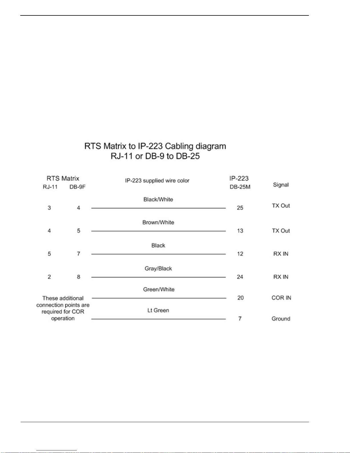
2.0 RTS Matrix to IP-223 Cabling
The R TS Matrix to IP-223 cabling diagram, shown in Figure 1, illustrates pinouts used to connect
an RTS Intercom to a Telex IP-223 Adapter Panel.
NOTE: RTS documents are available at: http://www.rtsintercoms.com/manuals/php.
REFERENCE: For more information, see the appropriate technical manual:
ADAM CS System Installation Guide (P/N 9330-7517-000)
ADAM Installation Guide (P/N 9330-7467-000)
Cronus User Manual (P/N 9350-7770-000)
ZEUS/ZEUSII User Guide (P/N 9330-7634-000)
ZEUSIII User Manual (P/N/ 9350-7843-000
FIGURE 1. RTS Matrix to IP-223 Cabling Diagram
4 AN-DISPATCH-035
Page 5
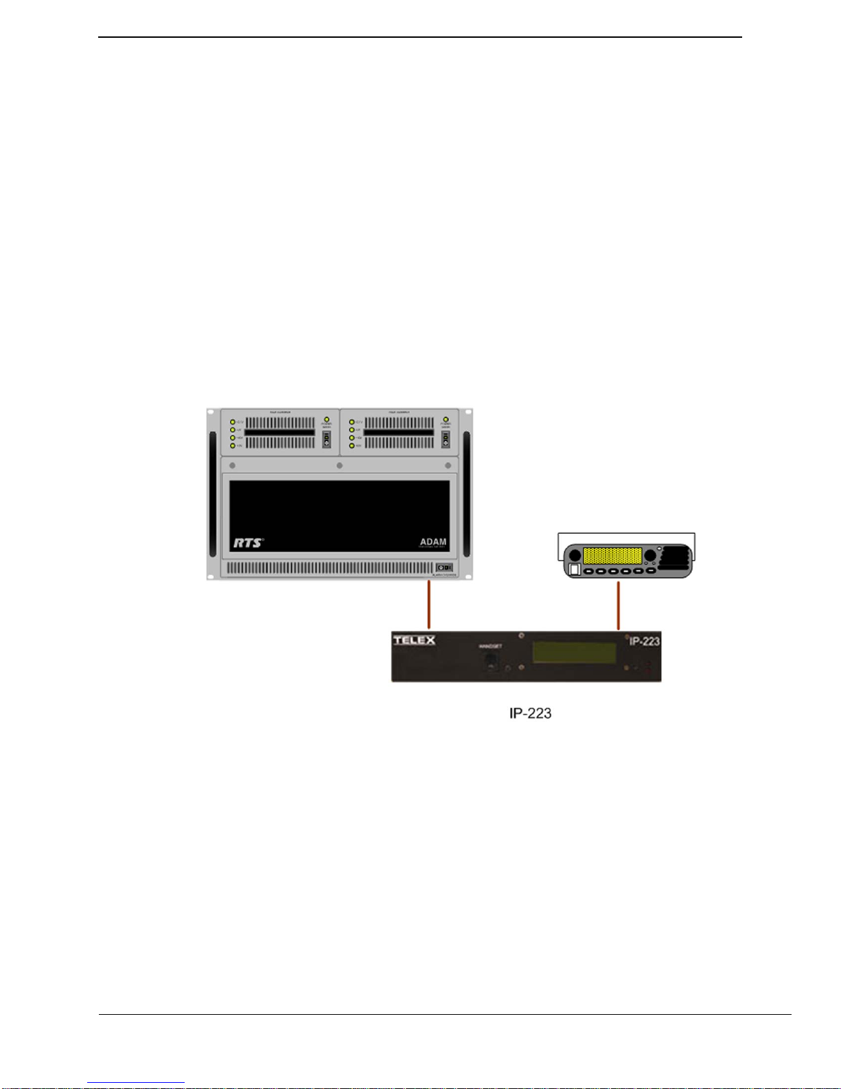
3.0 LMR Configuration Example
A line to line configuration example using an LMR is shown in Figure 2. The line to line
crosspatch is enabled in the IP-223. Control logic and audio (6-wire E&M) are generated by the
RTS system; these are connected to Line 2 I/O on the Ip-223 which is configured for local mode
operation.
Line 1 I/O of the IP-223 is also configured for local mode operation and is directly connected to a
LMR radio.
Receive audio from the LMR is connected to the IP-223’s Line 1 I/O. Based on COR (Carrier
Operated Relay) or LAM (Line Activity Monitor), the IP-223 passes this audio to the IP-223’s
Line 2 and out to the RTS Intercom System for playback at keypanels. P T T commands at the
keypanel generate a relay closure that activates the COR logic at the IP-223. The IP-223 then
accepts audio on its Line 2 input. The crosspatch transfers the audio from Line 2 to Line 1 and a
relay closure is activated to key the LMR. Audio is passed from the IP-223 Line 1 to modulate the
LMR.
IP-223 to RTS Intercom Products
FIGURE 2. Line to Line Configuration Example
3.1 IP-223 Setup
The IP-223 is configured for local mode operation on both Line 1 and Line 2 and a
line-to-line crosspatch is enabled.
NOTE: The IP-223’s default username is admin and the password is blank.
AN-DISPATCH-035 5
Page 6

IP-223 to RTS Intercom Products
3.1.1 Multicast Address Setup Window
The Multicast Address Setup window, shown in Figure 3, is used to configure the
line type for Lines 1 and 2.
To configure Lines 1 and 2 for an LMR configuration, do the following.
1. Click Multicast Address Setup.
2. From Line 1’s Line Type drop down menu, select Local Mode.
3. From Line 2’s Line Type drop down menu, select Local Mode.
4. Click Submit.
The Multicast Address Setup configuration is temporarily saved.
5. Click Save to EEPROM.
The EEPROM window appears.
6. Click Save Parameters.
All configurations are permanently saved to the IP-223 console.
FIGURE 3. Multicast Address Setup Window, Line to Line Configuration
6 AN-DISPATCH-035
Page 7
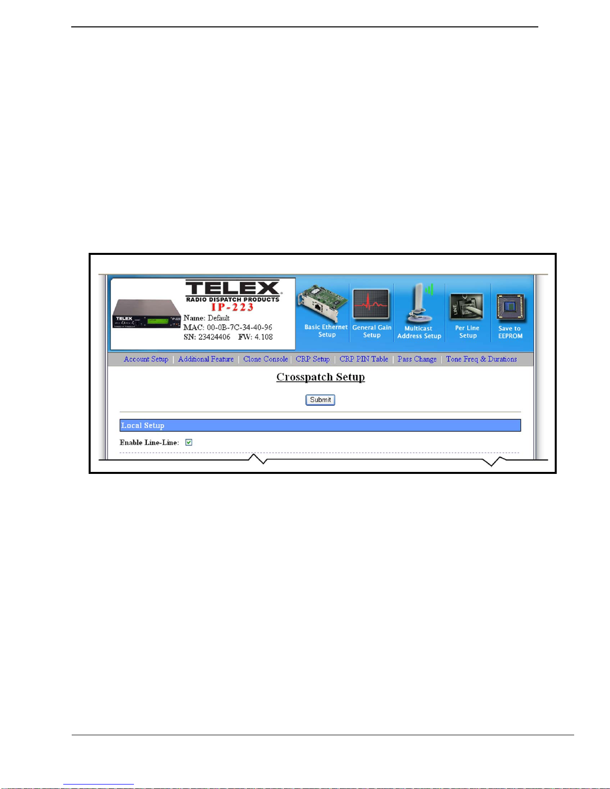
3.1.2 Crosspatch Setup Window
The Crosspatch Setup window, shown in Figure 4, is used to set up a crosspatch.
To enable crosspatching, do the following:
1. Click CRP Setup.
The Crosspatch Setup window appears.
2. Select the Enable Line-Line check box.
Crosspatching is enabled.
3. Click Submit.
The Crosspatch Setup configuration is temporarily saved.
4. Click Save to EEPROM.
The EEPROM window appears.
5. Click Save Parameters.
All configurations are permanently saved to the IP-223 console.
IP-223 to RTS Intercom Products
FIGURE 4. Crosspatch Setup Window
3.1.3 Per Line Setup Window Line 1
The Per Line Setup window is used to configure per line setup. Line 1
configuration depends on the type of radio interface.
REFERENCE: For more information about special configuration requirements on
Line 2 for the type of radio connected, see the IP-223 Technical
Manual (P/N 803641) or the appropriate application note.
AN-DISPATCH-035 7
Page 8

IP-223 to RTS Intercom Products
3.1.4 Per Line Setup Window Line 2
The Per Line Setup window, shown in Figure 5, is used to setup the connection to
the RTS equipment. Depending on the connection to the RTS equipment, VOX or
COR triggering may be used.
To configure an RTS supplied relay closure, do the following:
1. Click Per Line Setup.
The Per Line Setup window appears.
2. Click Line Select 2.
The Per Line Setup window for Line 2 appears.
3. Select the COR Enabled check box on Line 2’s Per Line Setup window.
The RTS supplied relay is enabled.
4. Click Submit.
The Per Line Setup configuration is temporarily saved.
5. Click Save to EEPROM.
The EEPROM window appears.
6. Click Save Parameters.
All configurations are permanently saved to the IP-223 console.
FIGURE 5. Per Line Setup Window, Local Mode–Line 2
8 AN-DISPATCH-035
Page 9
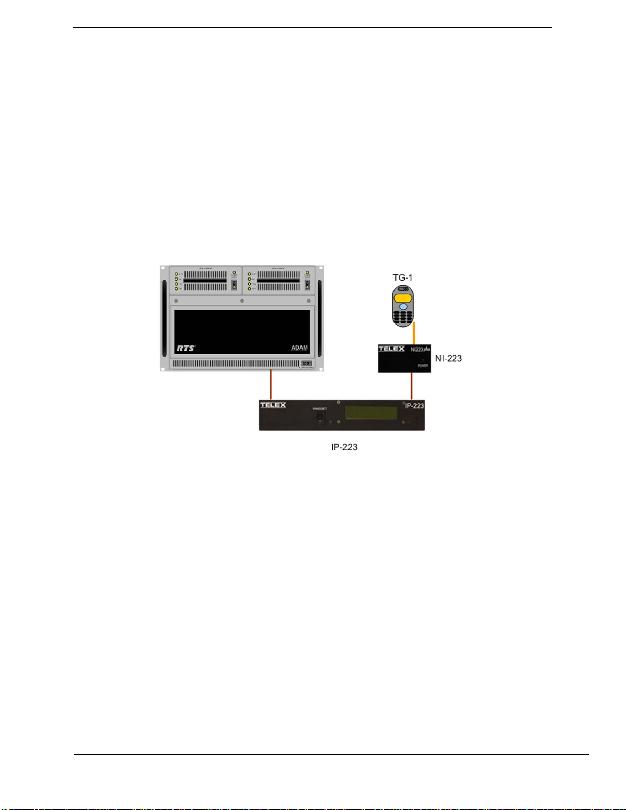
4.0 iDEN Configuration Example
An iDEN configuration example is shown in Figure 6. Line-to-line Crosspatch is enabled in the
IP-223. Control logic and audio (6-wire E&M) are generated by the RTS system; these are
connected to Line 2 I/O which is configured for local mode operation. Line 1 I/O of the IP-223 is
also configured for local mode operation with iDEN as the selected radio. A Telex NI-223 is
required for this interface.
Receive audio from the iDEN is connected to the Line 1 I/O of the IP-223. Based on LAM levels,
the IP-223 passes the audio to Line 2 and out to the RTS Intercom System for playback at
keypanels. P TT commands at the keypanel generate a relay closure that activates the COR logic at
the IP-223. The IP-223 then accepts audio on its Line 2 input. The crosspatch transfers the audio
from Line 2 to Line 1, and a relay closure is activated to key the iDEN. Audio is passed from the
IP-223 Line 1 to modulate the iDEN.
IP-223 to RTS Intercom Products
FIGURE 6. iDEN Configuration Example
4.1 IP-223 Setup
Configure the IP-223 for iDEN on Line 1 and local mode operation on line 2.
NOTE:
• The IP-223’s default username is admin and the password is blank.
• The Line-Line check box on the Crosspatch window and F1 Last Call check box
on the Per Line Setup for Line 1 must be selected.
AN-DISPATCH-035 9
Page 10

IP-223 to RTS Intercom Products
4.1.1 Multicast Address Setup Window
The Multicast Address Setup window, shown in Figure 7, is used to configure the
line type.
To configure an iDEN type on Line 1, do the following.
1. Click Multicast Address Setup.
The Multicast Address Setup window appears.
2. From Line 1’s Line Type drop down menu, select iDEN Radio.
3. From Line 2’s Line Type drop down menu, select Local Mode.
4. Click Submit.
The Multicast Address configuration is temporarily saved.
5. Click Save to EEPROM.
The EEPROM window appears.
6. Click Save Parameters.
All configurations are permanently saved to the IP-223 console.
NOTE: No other Multicast Address Setup window changes are required for iDEN
configuration.
FIGURE 7. Multicast Address Setup Window, iDEN Configuration
10 AN-DISPATCH-035
Page 11

4.1.2 Crosspatch Setup Window
The Crosspatch Setup window, shown in Figure 4, is used to enable line-to-line
crosspatching.
To enable a crosspatch for an iDEN radio, do the following:
1. Click CRP Setup
The Crosspatch Setup window appears.
2. Select the Enable Line-Line check box.
Crosspatching is enabled.
3. Click Submit.
The Crosspatch configuration is temporarily saved.
4. Click Save to EEPROM.
The EEPROM window appears.
5. Click Save Parameters.
All configurations are permanently saved to the IP-223 console.
4.1.3 Per-Line Setup Window Line 1
The Per Line Setup window for Line 1, shown in Figure 8, is used to setup LAM
and activate options such as F1 Last Call, Full Duplex, and RxACG.
IP-223 to RTS Intercom Products
The recommended LAM level is -25dB. However, the optimum level may vary
depending on the terminal attachment (iDEN handset). Handset volume is adjusted
to present clear receive audio and the LAM level is set to block unwanted noise. A
LAM time of three (3) seconds is recommended to avoid continual switching of
receive audio.
AN-DISPATCH-035 11
Page 12

IP-223 to RTS Intercom Products
REFERENCE: For more information, see the NI-223+ Technical Manual
(P/N 804165) for jumper settings and alignment procedures for
Line 1.
FIGURE 8. Per Line Setup Window, iDEN Radio–Line 1
12 AN-DISPATCH-035
Page 13

4.1.4 Per Line Setup Window Line 2
The Per Line Setup window for Line 2, shown in Figure 9, is used to set up COR or
VOX triggering and audio levels. Depending on the connection to the RTS
equipment, VOX or COR triggering may be used.
To configure an RTS supplied relay closure for an iDEN radio connection, do
the following:
1. Click Per Line Setup.
The Per Line Setup window appears.
2. Click Line Select 2.
The Per Line Setup window for Line 2 appears.
3. Select the COR Enabled check box.
4. Click Submit.
The configuration is temporarily saved.
5. Click Save to EEPROM.
The EEPROM window appears.
6. Click Save Parameters.
All configurations are permanently saved to the IP-223 console.
IP-223 to RTS Intercom Products
To configure PTT with VOX for an iDEN radio connection, do the following:
1. Click Per Line Setup.
The Per Line Setup window appears.
2. Click Line Select 2.
The Per Line Setup window for line 2 appears.
3. In the LAM Level dB field, enter the level in dB.
4. In the LAM Time field, enter three (3) seconds.
5. Click Submit.
The configuration is temporarily saved.
6. Click Save to EEPROM.
The EEPROM window appears.
7. Click Save Parameters.
All configurations are permanently saved to the IP-223 console.
NOTE: The recommended LAM level is -20dB to -25dB.
AN-DISPATCH-035 13
Page 14

IP-223 to RTS Intercom Products
FIGURE 9. Per Line Setup Window, Local Mode–Line 2
14 AN-DISPATCH-035
Page 15

IP-223 to RTS Intercom Products
5.0 WAN/LAN Remote Configuration Example
The Telex IP-223 Adapter Panel can be employed to provide access to remote radio devices over
a LAN or WAN. See Figure 10.
Receive audio from the LMR, or iDEN handset, is connected to the line’s I/O (DB-25) of the
remote IP-223. This audio is passed, via the IP network, to the corresponding line I/O of the local
IP-223. A PTT command, and audio, from the RTS keypanel, received at the local IP-223 line
I/O, are passed across the IP network to the remote IP-223. The remote IP-223 keys the radio
device and passes audio for transmission.
FIGURE 10. LAN/WAN Configuration Example
5.1 Local IP-223 Setup
The locally connected IP-223 must to be configured for local mode operation on both lines.
The Line Type and jumper settings should be appropriately configured for the device being
connected. The following example uses an iDEN handset.
NOTE: The IP-223’s default username is admin and the password is blank.
REFERENCE: For more information, see the IP-223 Technical Manual (P/N 803641) for
jumper settings relevant to the RTS equipment to be connected.
AN-DISPATCH-035 15
Page 16

IP-223 to RTS Intercom Products
5.1.1 Local IP-223 Multicast Address Setup Window
NOTE: Both Unicast and Multicast are supported for this feature.
See examples shown in Figure 11 and Figure 13.
To configure a unicast system, do the following:
1. From the local IP-223 configuration webpage, click Multicast Address Setup.
The Multicast Address Setup window appears.
2. Enter the static IP Address of the remote IP-223 in:
3. Click Submit.
The Multicast Address Setup configuration is temporarily saved.
4. Click Save to EEPROM.
The EEPROM window appears.
5. Click Save Parameters.
All configurations are permanently saved to the IP-223 console.
To configure a multicast system, do the following:
Line 1’s Rx and Tx Mcast Address fields.
Line 2’s Rx and Tx Mcast Address fields.
1. From the local IP-223 configuration webpage, click Multicast Address Setup.
The Multicast Address Setup window appears.
2. Enter the same Multicast Address in:
Line 1’s Rx and Tx Mcast Address fields.
Line 2’s Rx and Tx Mcast Address fields.
3. Click Submit.
The Multicast Address Setup configuration is temporarily saved.
4. Click Save to EEPROM.
The EEPROM window appears.
5. Click Save Parameters.
All configurations are permanently saved to the IP-223 console.
NOTE: The range for Multicast Addresses is 224.0.0.2 to 239.255.255.255.
16 AN-DISPATCH-035
Page 17

IP-223 to RTS Intercom Products
To configure the Rx and Tx port numbers, do the following:
> From the local IP-223 Multicast Address Setup window, in:
• Line 1’s Rx Port field, enter an Rx port number for Line 1 (for example
1054).
• Line 1’s Tx Port field, enter a Tx port number for Line 1 (for example
1072).
• Line 2’s Rx Port field, enter an Rx port number for Line 2 (for example
1055).
• Line 2’s Tx Port field, enter a Tx port number for Line 2 (for example
1073).
NOTE: The range for the Tx and Rx port number fields is 1054 to 65535.
FIGURE 11. Multicast Address Setup Window, WAN/LAN Configuration –Local IP-223
AN-DISPATCH-035 17
Page 18

IP-223 to RTS Intercom Products
5.1.2 Local IP-223 Per Line Setup Window Lines 1 & 2
Depending on the connection to the R TS equipment, VOX or COR triggering maybe
used.
To configure an RTS supplied relay closure for a WAN/LAN system, do the
following:
1. Click Per Line Setup.
The Per Line Setup window appears.
2. Click Line Select 2.
The Per Line Setup window for Line 2 appears.
3. Select the COR Enabled check box.
4. Click Submit.
The Multicast Address Setup configuration is temporarily saved.
5. Click Save to EEPROM.
The EEPROM window appears.
6. Click Save Parameters.
All configurations are permanently saved to the IP-223 console.
To configure PTT with VOX for a WAN/LAN system, do the following:
1. In the LAM Level dB field, enter the level in dB.
2. In the LAM Time field, enter three (3) seconds.
3. Click Submit.
The Multicast Address Setup configuration is temporarily saved.
4. Click Save to EEPROM.
The EEPROM window appears.
5. Click Save Parameters.
All configurations are permanently saved to the IP-223 console.
NOTE: The recommended LAM level is -20dB to -25dB.
FIGURE 12. Per Line Setup Window WAN/LAN, Local Mode–Line 2
18 AN-DISPATCH-035
Page 19

IP-223 to RTS Intercom Products
5.2 IP-223 Remote Setup
The remote IP-223 must be configured for local mode operation on both lines.
NOTE: The IP-223’s default username is admin and the password is blank.
REFERENCE: For more information, see the IP-223 Technical Manual (P/N803641) for
jumper settings relevant to the RTS equipment to be connected.
5.2.1 Remote IP-223 Multicast Address Setup Window
NOTE: Both Unicast and Multicast are supported for this feature.
See examples shown in Figure 11 and Figure 13.
To configure a unicast system, do the following:
1. From the remote IP-223 configuration webpage, click Multicast Address Setup.
The Multicast Address Setup window appears.
2. Enter the static IP Address of the local IP-223 in:
Line 1’s Rx and Tx Mcast Address fields.
Line 2’s Rx and Tx Mcast Address fields.
3. Click Submit.
The Multicast Address Setup configuration is temporarily saved.
4. Click Save to EEPROM.
The EEPROM window appears.
5. Click Save Parameters.
All configurations are permanently saved to the IP-223 console.
To configure a multicast system, do the following:
1. From the remote IP-223 configuration webpage, click Multicast Address Setup.
The Multicast Address Setup window appears.
2. Enter the same Multicast Address used in the local IP Setup in:
Line 1’s Rx and Tx Mcast Address fields.
Line 2’s Rx and Tx Mcast Address fields.
3. Click Save to EEPROM.
The EEPROM window appears.
4. Click Save Parameters.
All configurations are permanently saved to the IP-223 console.
NOTE: The range for Multicast Addresses is 224.0.0.2 to 239.255.255.255.
AN-DISPATCH-035 19
Page 20

IP-223 to RTS Intercom Products
To configure the Rx and Tx port numbers, do the following:
From the remote IP-223 Multicast Address Setup window, in:
1. Line 1’s Rx Port field, enter the same port number as the local IP-223’s Tx port
number for Line 1 (for example 1072).
2. Line 1’s Tx Port field, enter the same port number as the local IP-223’s Rx port
number for Line 1 (for example 1054).
3. Line 2’s Rx Port field, enter the same port number as the local IP-223’s Tx port
number for Line 2 (for example 1073).
4. Line 2’s Tx Port field, enter the same port number as the local IP-223’s Rx port
number for Line 2 (for example 1055).
5. Click Save to EEPROM.
The EEPROM window appears.
6. Click Save Parameters.
All configurations are permanently saved to the IP-223 console.
NOTE: The range for the Rx Port field and Tx Port field is 1054 to 65535.
FIGURE 13. Multicast Address Setup Window, WAN/LAN Configuration–Remote IP-223
5.2.2 Remote IP-223 Per Line Setup Windows Line 1 and 2
REFERENCE: For more information, see the IP-223 Technical Manual (P/N
20 AN-DISPATCH-035
803641) or appropriate application note for any special IP-223
configuration requirements on Line 1 and Line 2 for the type of
radio connected.
Page 21

IP-223 to RTS Intercom Products
6.0 Remote Tone Control Configuration Example
FIGURE 14. Remote Tone Control Example
Line to Line Crosspatch, see Figure 14, is enabled in the IP-223. Control logic and audio (6-wire
E&M) are generated by the R TS system; these are connected to Line 2 I/O on the IP-223 which is
configured for Local mode operation. Line 1 I/O of the IP223 is configured for Tone mode
operation and is connected to a 2- or 4-wire lease line for Tone Remote operation of a LMR
mobile radio. Industry standard radio control tones are generated and coupled with voice audio for
control of distant radio locations. Control tones are decoded by either a Telex TRA-223 or
DSP-223 Tone Remote Adaptor which is directly connected to the LMR radio.
Receive audio from the LMR is connected to the I/O of the DSP-223 and amplified down the
2- or 4-wire line to Line 1 I/O of the IP-223. The IP-223 based on LAM passes audio to Line 2 of
the IP-223 and out to the RTS Intercom System for playback at keypanels. PTT commands on a
keypanel generate a relay closure and audio is inserted on Line 2 of the IP-223 COR and audio
inputs. This creates a P TT tone generation sent out Line 1 of the IP-223 onto the 2- or 4-wire line
to the remote radio adaptor, the tone is decoded and a relay closure to key the LMR is generated,
audio is coupled and passed to the radio.
6.1 IP-223 Setup
The IP-223 must be configured for tone mode operation on line 1 and local mode on Line 2.
NOTE: The IP-223’s default username is admin and the password is blank.
REFERENCE: For more information, see the IP-223 Technical Manual (P/N 803641) for
jumper settings relevant to the RTS equipment to be connected.
AN-DISPATCH-035 21
Page 22

IP-223 to RTS Intercom Products
6.1.1 Multicast Address Setup Window
To configure the IP-223 for remote tone control, do the following:
1. Click Multicast Address Setup.
The Multicast Address Setup window appears.
2. From the Line Type drop down menu for Line 1, select Tone Mode.
3. From the Line Type drop down menu for Line 2, select Local Mode.
4. Click CRP Setup.
The Crosspatch Setup window appears.
5. Select the Enable Line-Line check box (full stop).
6. Click Submit.
The Multicast Address Setup configuration is temporarily saved.
7. Click Save to EEPROM.
The EEPROM window appears.
8. Click Save Parameters
All configurations are permanently saved to the IP-223 console.
FIGURE 15. Multicast Address Setup, Remote Tone Control Configuration
22 AN-DISPATCH-035
Page 23

6.1.2 Per Line Setup Window Line 1
The Per Line Setup window, shown in Figure 16, require no changes although,
various fields and options can be set based on the line type being configured.
REFERENCE: For more information, see the IP-223 Technical Manual
(P/N 803641).
IP-223 to RTS Intercom Products
FIGURE 16. Per Line Setup Window, Tone Mode–Line 1
AN-DISPATCH-035 23
Page 24

IP-223 to RTS Intercom Products
6.1.3 Per Line Setup Window Line 2
Depending on the connection to the RTS equipment, VOX or COR triggering may
be used. If a relay closure from the RTS equipment is supplied, the COR Enabled
check box must be selected on Line 2’s Per Line Setup window. An example is
shown in Figure 17.
To configure an RTS supplied r elay closure for a r emote tone contr ol system, do
the following:
1. Click Per Line Setup.
The Per Line Setup window appears.
2. Select the COR Enabled check box. See Figure 17.
3. Click Submit.
The Per Line Setup configurations are temporarily saved.
FIGURE 17. Per Line Set Window, Local Mode–Line 2
24 AN-DISPATCH-035
Page 25

IP-223 to RTS Intercom Products
To configure PTT with VOX for a remote tone control system, do the following:
1. Click Per Line Setup.
The Per Line Setup window appears.
1. In the LAM Level dB field, enter the level in dB.
2. In the LAM Time field, enter three (3) seconds.
3. Click Submit.
The Per Line Setup configurations are temporarily saved.
4. Click Save to EEPROM.
The EEPROM window appears.
5. Click Save Parameters.
All configurations are permanently saved to the IP-223 console.
NOTE: The recommended LAM level is -20dB to -25dB.
FIGURE 18. Per Line Setup Window, Local Mode– Line 2
AN-DISPATCH-035 25
Page 26

IP-223 to RTS Intercom Products
7.0 Radio Connection Chart
Table 1 lists popular radios supported.by the IP-223.
Manufacturer
BK/Relm GMH 1 AN-DISPATCH-017
BK/Relm RM Series 1 AN-DISPATCH-019
Datron Guardian 1 AN-DISPATCH-015
EF Johnson RS-5300 100 IP-25300
ICOM F121/221 1 AN-DISPATCH-022
ICOM A200 1 AN-DISPATCH-033
Kenwood TK-863 1 AN-DISPATCH-008
Kenwood TK-x80 100 AN-DISPATCH-001
Kenwood TK-x90 100 301957000 AN-DISPATCH-001
Kenwood TK-x150 100 301956000 AN-DISPATCH-001
Kenwood TK-x180 100 301956000 AN-DISPATCH-001
Kenwood TK-57/5810 100 301956000 AN-DISPATCH-001
Kenwood TK-6110 1 AN-DISPATCH-023
Kenwood TKR-x40 32
Kenwood TKR-x50 16 AN-DISPATCH-021
M/A Com-Ericsson GE M7100 1 AN-DISPATCH-032
Midland Base Tech II 16
Motorola Astro Spectra 1
Motorola CDM/PRO 16 301969000 AN-DISPATCH-009
Motorola DIU-3000 1
Motorola MCS2000 1 AN-DISPATCH-020
Motorola XTL Series 1 AN-DISPATCH-010
Motorola Old mobiles 1 AN-DISPATCH-006
Raytheon/JPS ACU DSP-1
Raytheon/JPS ACU-HSP-2
Raytheon/JPS NXU-2
Sepura SRM2000 100 301961000 AN-DISPATCH-011
Sprint/Nextel Falcon Series 100 NI-223
Tait TB-7100 16
Vertex
Table 1: Radio Cable Part Numbers and Application Note References
Manufacturer’s
Model Number
VX-4100/4200
VX-5500
VX-7200
Line Qty
16
T elex Cable
Assy P/N or
Product
Telex Application
Note
AN-DISPATCH-016
AN-DISPATCH-031
26 AN-DISPATCH-035
Page 27

IP-223 to RTS Intercom Products
Table 2 lists cable assemblies required to connect the specified device to a Telex V.I.P.E.R.
Cable
Manufacturer Model Line Qty
Assembly
Application Note
or Product
T actical Radios URC and PRC 1 400100161
LPX, LPU, LPH,
BK/Relm
ICOM F3/F4 400100144
ICOM F30GS/F40GS 400100156
ICOM A3 400100148
ICOM
Kenwood
Kenwood
M/A-COM-Ericsson GE MRK, Prism 400100139
M/A-COM-Ericsson GE KPC 400100143
M/A-COM-Ericsson GE LPE 400100154
M/A-COM-Ericsson GE Jaguar 400100160
Motorola
Motorola HT750, 1250 400100152
Motorola EX500 400100162
Motorola
Motorola
Vertex VX210 400100155
Vertex VX800 400100153
Table 2: Viper Cable Part Number Information
3142, LMH, EPU,
EPH
F11/F21/F3GS/
F4GS
TK220, 320, 240,
248, 250, 350, 260,
270, TH91A, AT,
E, TH25A
TK280, 380, 290,
480, 481
SABRE, MX1000,
ASTRO
GP300, G Tx, P110,
HT1225, P1225,
SP50, GP1250,
LTS2000
HT1000, MT2000,
MTS2000,
MTx838,
MTx2000,
MTx80000,
MTx9000,
XTx3000,
GP1200, JT1000
400100093
400100159
400100043
400100150
400100069
400100130
400100135
AN-DISPATCH-035 27
Page 28

IP-223 to RTS Intercom Products
28 AN-DISPATCH-035
Page 29

Revision History
Document Title: IP-223 to RTS Intercom Products
Document Number: AN-DISPATCH-035
Revision Change Description Date
A Initial Release 05-AUG-2009
Suggestions or comments:
Contact technical support with suggestions or comments concerning this application note.
Technical Support:
Email: TelexDispatchtechsupport@us.bosch.com
Fax: 1-402-467-3279
Phone: 1-800-898-6723
Bosch Security Systems, Inc.
8601 East Cornhusker Highway
Lincoln Nebraska 68507
Phone: (800) 752-7560 Fax: (402) 467-3279
Email: Telexdispatch@us.bosch.com
Web: www.telex.com
29
Page 30

 Loading...