

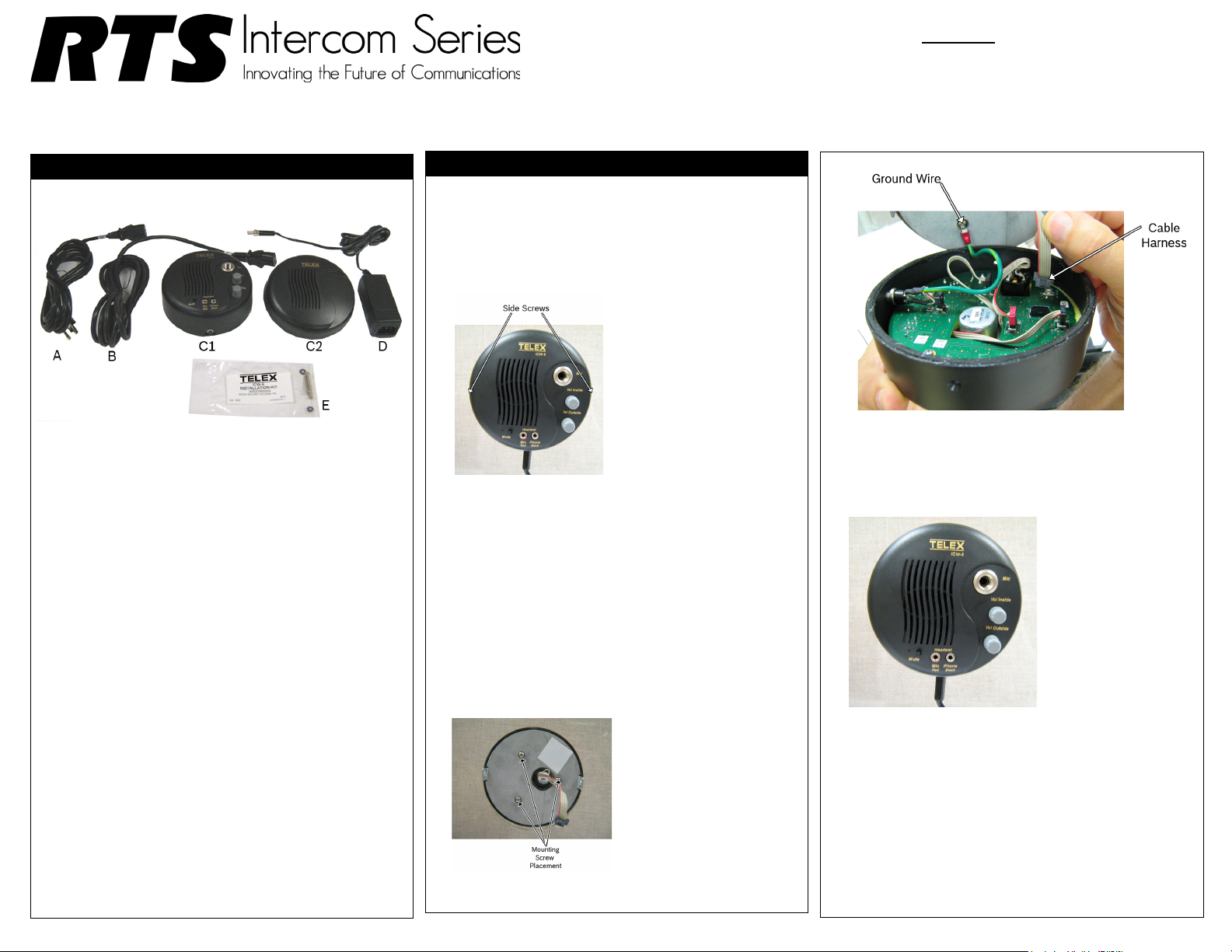
CAUTION: Do not allow
the intercom to hang from
the ground wire. The wire
connection may break.
Quick Start Guide for ICW-6 Window Intercom
NOTICE
USE THE POWER SUPPLY INCLUDED WITH THE ICW-6.
USE OF ANY OTHER POWER SUPPLY COULD DAMAGE
THE ICW-6 AND WILL VOID THE WARRANTY.
Packing list
Please inspect package contents
Included Parts
A. Cordset - European
B. Cordset - U.S.A.
C. ICW-6 Final Assembly
1. Operator-Side Assembly
2. Customer-Side Assembly
D. Switching Power Supply
E. Installation Kit
• #6 screws 1” (3)
• #6 washers (3)
•Cable Tie
F. User Manual (not shown)
G. Mounting Template (not shown)
H. Quick Start Guide (not shown)
I. Warranty (not shown)
Recommended Tools
• No. 1 Phillips screwdriver
• Equipment for cutting/drilling hole(s) for mounting
• 1” wide transparent tape
Installation
To install the ICW-6 window intercom, do the following:
1. On the operator unit, remove the two (2) side screws holding the mounting plate to the operator assembly.
NOTE: To adjust the mic sensitivity, see “Inside Mic
Sensitivity Adjustment” on page 2
2. Measure and identify the location where the intercom is to be mounted.
3. Attach the mounting template (included in box - P/N LIT000401000) to the window (customer unit side) being sure to center the appropriate guide in the location identified.
4. Cut and/or drill the holes from the customer unit side.
5. Have an assistant place the customer unit against the window. Make sure the holes line up correctly.
6. Attach the mounting plate removed from the operator assembly using the three (3) supplied mounting screws and rubber washers.
.
8. Attach the cable harness from the customer unit to the connector on the operator unit.
9. Attach the operator unit to the mounting plate using the side screws.
10. Screw the threaded end of the ICW-6 power supply
interface cord into the ICW-6.
The connector is located on the bottom of the ICW-6 on
the operator unit.
11. Secure the cord to the glass using wide clear adhesive.
12. Connect the power supply to AC power using the supplied power cord.
F.01U.196.220 Rev 03 12/2012 Copyright Bosch Security Systems 2012 Printed in USA
7. Remove the lower left screw and washer and attach the
ground wire.
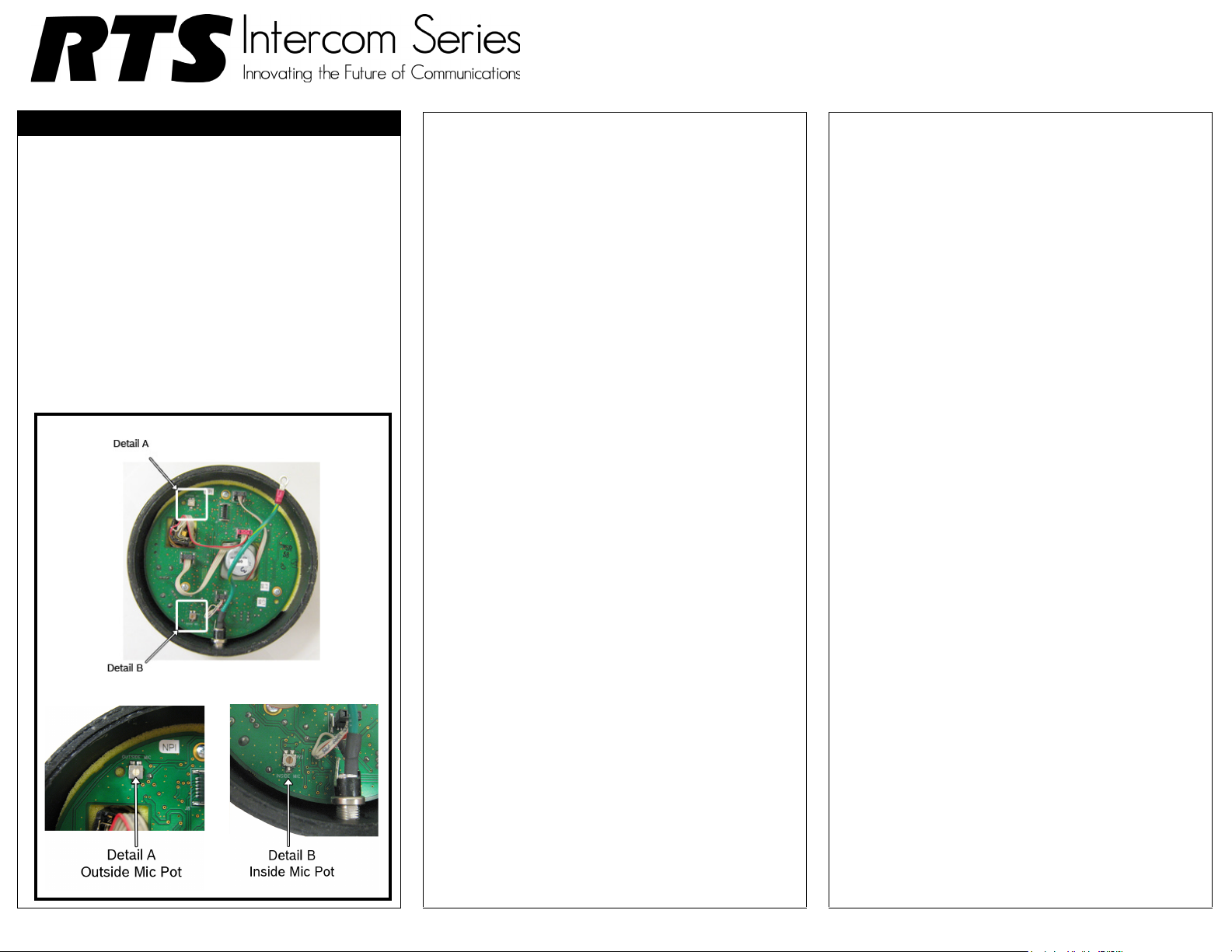
Inside Mic Sensitivity Adjustment
On the ICW-6, you can adjust the sensitivity of the inside
and outside mic. This means the how far away from the
microphone a person can stand to talk and still be heard.
Mic Adjustment Pot Location
By default, the following applies:
• The inside mic is set midpoint, 2”- 3”
Speak Zone
• The outside mic is set midpoint, 1’ - 2’
Speak Zone
To adjust the inside or outside mic sensitivity level, do
the following:
1. Using a small screwdriver, remove the two (2) side screws from the operator side unit.
2. Carefully remove the back plate from the operator side unit.
3. Locate the mic pot you want to adjust.
4. With a flathead screwdriver, turn the mic pot clockwise to increase the sensitivity. OR Turn the mic pot counter-clockwise to decrease the sensitivity.
 Loading...