

Page 1
Installation and Operation Instructions
b
®
111111111111
222222222222
333333333333
444444444444
555555555555
666666666666
IC-6SX
Source Assign Panel
Channel 1
Channel 2
Channel 3
Channel 4
Channel 5
Channel 6
OUTPUTS
1 2 3 4 5 6 7 8 9 10 11 12
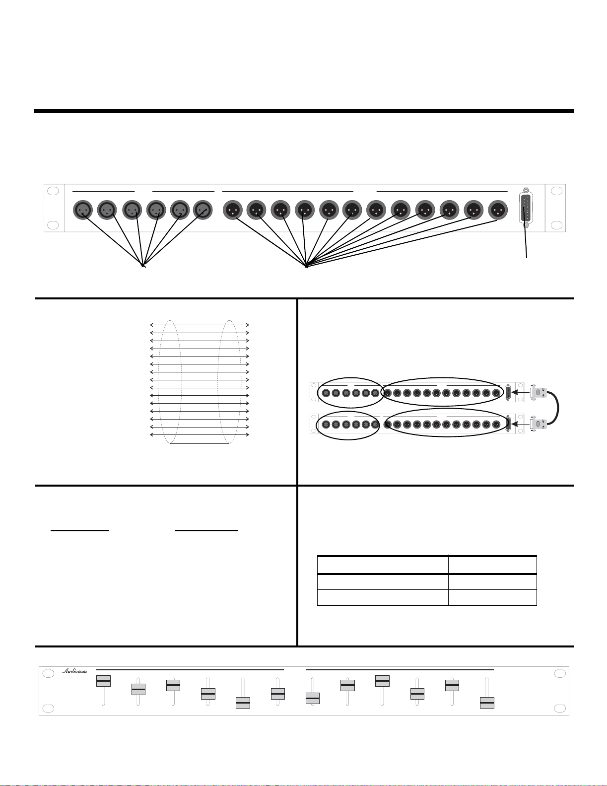
IC-6SX Source Assignment Panel
INSTALLATION: When the cable is plugged into either the input or the output channels, it locks in place. On
the input channels, push the Silver tab to release the plug.
INPUTS
123456 123456789101112
INPUTS OUTPUTS
TELEX COMMUNICATIONS, INC. MADE IN USA
OUTPUT CHANNELS
1
2
3
4
5
6
7
8
9
10
11
12
13
14
Link Cable
Wiring
INPUT CHANNELS
15-pin Male D-sub
1
2
3
4
5
6
7
8
9
10
11
12
13
14
15 15
NOTE: An optional pre-wired, unshielded cable is availa
Use p/n: 9002-7690-000 when ordering
EXPANSION CONNECTOR (15-PIN
D-SUB FEMALE) PINOUT
Description
Pin Number
Channel 1 Audio 1, 9
Channel 2 Audio 2, 10
Channel 3 Audio 3, 11
Channel 4 Audio 4, 12
Channel 5 Audio 5, 13
Channel 6 Audio 6, 14
Signal Common (GND) 7, 8, 15
IC-6SX SOURCE ASSIGN PANEL
Links two IC-6SX units
LINKING TWO UNITS TOGETHER
15-pin Male D-sub
Inputs 1-6
INPUTS
INPUTS
TELEXCOMMUNICATIONS, INC. MADEIN USA
INPUTS
INPUTS
1122334455661122334455667788991010111112
TELEXCOMMUNICATIONS, INC. MADEIN USA
Inputs Not
Used
Outputs 1-12
OUTPUTS
IC-6SXSOURCE ASSIGN PANEL
OUTPUTS
IC-6SXSOURCE ASSIGN PANEL
Outputs 13-24
12
Expansion
Cable
Input (3 pin XLR Female) & Output (3 pin XLR Male)
Connector
Table 1:
Description Pin Number(s)
Signal Common (GND) 1
Balanced Audio 2,3
EXPANSION
together
EXPANSION
EXPANSION
IC-6SX
Source Assign Panel
Channel 1
Channel 2
Channel 3
Channel 4
Channel 5
Channel 6
Set Switches to assign input channels to output channels
9350-7690-000 Rev C 4-2006
Page 2

SPECIFICATIONS
Dimensions:.................................................................H: 1.75” (44.5 mm) W: 19.0” (482 mm) D: 3.85” (98 mm)
Weight: .........................................................................................................................................3.44lbs. (1.55 kg)
Power:................................................................................................................................................................ N/A
Matrix Type: ..........................................................................................................Passive, Mechanically Switched
Inputs:......................................................................................................................6, Balanced, Female XLR type
Outputs ..................................................................................................................... 12, Balanced, Male XLR type
PROPRIETARY NOTICE
The product information and design disclosed herein were originated by
and are the property of Telex Communications, Inc. Telex reserves all
patent, proprietary design, manufacturing, reproduction, use and sales
rights thereto, and to any article disclosed therein, except to the extent
rights are expressly granted to others.
COPYRIGHT NOTICE
Copyright 2006 by Telex Communications, Inc. All rights reserved.
Reproduction, in whole or in part, without prior written permission from
Telex is prohibited.
WARRANTY NOTICE
See the enclosed warranty card for further details.
CUSTOMER SUPPORT
Technical questions should be directed to:
Customer Service Department
RTS/Telex Communications, Inc.
12000 Portland Avenue South
Burnsville, MN 55337 USA
Telephone: 800-392-3497
Fax: 800-323-0498
Factory Service: 800-553-5992
RETURN SHIPPING INSTRUCTIONS
Customer Service Department
Telex Communications, Inc. (Lincoln, NE)
Telephone: 402-467-5321
Fax: 402-467-3279
Factory Service: 800-553-5992
Please include a note in the box which supplies the company name,
address, phone number, a person to contact regarding the repair, the type
and quantity of equipment, a description of the problem and the serial
number(s).
SHIPPING TO THE MANUFACTURER
All shipments of product should be made via UPS Ground, prepaid (you
may request from Factory Service a different shipment method). Any
shipment upgrades will be paid by the customer. The equipment should
be shipped in the original packing carton. If the original carton is not
available, use any suitable container that is rigid and of adequate size. If
a substitute container is used, the equipment should be wrapped in paper
and surrounded with at least four (4) inches of excelsior or similar
shock-absorbing material. All shipments must be sent to the following
address and must include the Proof of Purchase for warranty repair.
Upon completion of any repair the equipment will be returned via
United Parcel Service or specified shipper, collect.
Factory Service Department
Telex Communications, Inc.
8601 Cornhusker Hwy.
Lincoln, NE 68507 U.S.A.
Attn: Service
 Loading...