

Page 1
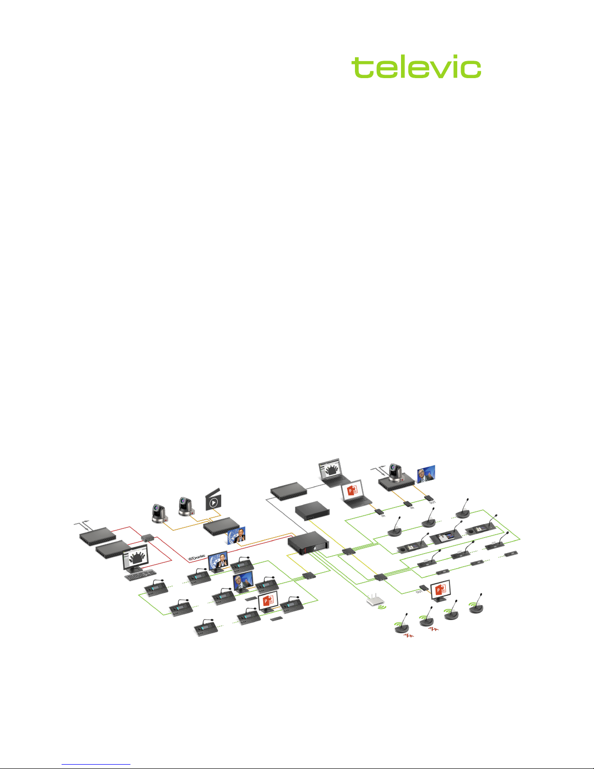
conference
PLIXUS
USER & INSTALLATION GUIDE
Page 2

Copyright Statement
No part of this publication or documentation accompanying this product may be reproduced in any form or
by any means or used to make any derivative such as translation, transformation, oradaptation without the
prior written permission of the publisher, except in case of brief quotations embodied in critical articles or
reviews. Contents are subject to change without prior notice.
Copyright © 2018 by Televic Conference NV. All rights reserved.
The authors of this manual have made every effort in the preparation of this book to ensure the accuracy of
the information. However, the information in this manual is supplied without warranty, either express or
implied. Neither the authors, Televic Conference NV, nor its dealers or distributors will be held liable for any
damages caused or alleged to be caused either directly or indirectly by this book.
Trademarks
All terms mentioned in this manual that are known to be trademarks or service marks have been
appropriately capitalized. Televic NV cannot attest to the accuracy of this information. Use of a term in this
book should not be regarded as affecting the validity of any trademark or service mark.
Page 3

CONTENTS
Introduction
Getting started 8
About this manual 8
Compatibility 9
9
Safety instructions 10
Safety 10
FCC &ICES Information 10
Conformity and Certification Info for Japan 11
Important safety instructions 12
Power connections 14
About Plixus 16
Concept anddesign 16
Plixus components
Components 18
General overview 18
Component range 20
Plixus MME 21
Overview 21
Control dialfunct ionality 21
Rear connectivity 23
Dante™ interface 24
Supported Video Formats 25
Factory defaults restore button 25
Plixus AE-R 26
Overview 26
Recording feature 26
Rear end connectivity 27
Power supply 27
Factory defaults restore button 27
Plixus power supply 28
Plixus AE-R power supply 28
Plixus power supply 28
3
Page 4

Plixus NEXT 29
DIPswitch table 30
General Network Extender Guidelines 30
Redundancy 31
Video In 33
Video-In box 33
Video request 34
Video-OUT 35
Video-Out box 35
Video selection 36
Video stream routing 37
Delegate equipment 38
Audio only equipment 38
Multimedia equipment 38
Interpreter equipment 39
Installation design
Plixus component properties 41
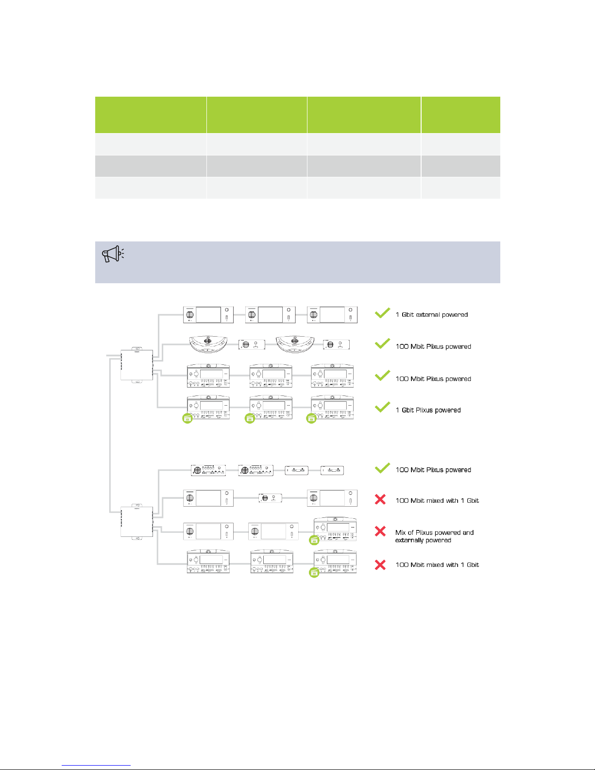
100 Mbit powered over Plixus Cable 41
1Gbit powered over Plixus cable 41
1Gbit externally powered 42
General installation guidelines 44
Units per branch / loop 44
When to use anetwork extender 44
Installation diagram 46
Configuration with Plixus engine only 46
Configuration with network extender 46
Examples 50
Power supply design 51
Power availability and consumption table 51
Plixus AE-R power supply 51
Calculator tool 52
Cabler equirements 52
Combine Plixus with Confidea G3 54
Combine wired and wireless units 54
Combine interpretation with wirelessunits 55
Range extension with multipleaccesspoints 56
Split andcombine rooms 57
Create redundancy 57
4
Page 5

Installation process
Introduction 60
Power supply 61
Power uniCOS units and network extenders 61
Power supply of the centr al unit 61
Install cables 63
Install microphones 64
General microphone characteristics 64
Technicalmicrophone characteristics 64
Microphone connector characteristics 65
Microphone Operation Modes 65
Install delegate units 67
Connect Plixus units 67
Connect to Plixus engine 67
Install Confidea G3 68
Connect WirelessConference AccessPoint (WCAP) to Plixus network 68
Configuration
Introduction 70
Plixus Core 70
Plixus Core versus CoCon 70
Configure IP settings 73
Change IP settings in Windows 73
Change IP settings in macOS 75
Getting started with Plixus Core 78
Activate Plixus Core 78
Explore Plixus Core 78
The Home page 81
Initialization 82
Introduction 82
How to initializeunits 83
Discussion options 85
Number of open microphones 85
Microphone mode 85
Microphone LED 87
Recording 88
Record usingthe record button 88
Record usingPlixus Core 88
Manage recor ded files 90
Audio settings 91
5
Page 6

General volume 91
Dynamics processing 91
Auto gain reduction 92
Audio routing 93
Audio routing configuration 93
Auxiliary levels 95
Additionaloptions 95
Interpretation 96
Add new language 96
Add Interpretation configuration from CoCon 97
Operator 98
Regional settings 99
Network settings 100
Network infor mation 100
Camera protocol 100
RESTAPI 101
Users 102
System info 103
Couple with Confidea G3 105
Couple WCAP with engine 105
Associate units with WCAP 106
Takeover WCAP 107
6
Page 7

INTRODUCTION
This chapter will give you a short introduction to this manual together with a
general description of the Plixus network and its functionalities.
Page 8
GETTING STARTED
About This Manual
Throughout this guide we use icons to designate different types of information:
This is a note. A note gives additional information, such as the meaning of the color of the
microphone LEDs. A note also provides information that may only be applicable to some situations.
This is a tip. A tip gives you an alternative way to do a particular step or procedure, or lets you know
of an option that you may find helpful.
This indicates that something is very important. Important information is something that you need to
do in order to accomplish a certain task.
This provides safety precaution information, that is, information that you need to be careful about to
prevent potential problems when using our systems.
GET TI NG S TAR TED 8
Page 9

Compatibility
This user manual applies to the following products:
Product Version
Plixus MME ≥
Plixus AE-R ≥ CRP 5.2
Confidea WCAP G3 ≥ 3.1
Confidea G3 delegate units ≥ 3.1
GET TI NG S TAR TED 9
Page 10

SAFETY INSTRUCTIONS
The safety instructions contain general safety guidelines that integrators, installers, operators, end users,
and anyone else who installs or uses Televic material is required to read and follow at all times.
Safety
All Televic systems are state of the art devices and have been designed to meet all quality standards.
Nevertheless, the individual components of the conference system can cause danger for persons and
material assets if
the conference system is not used as intended,
the conference system is set up by personnel not familiar with the safety regulations,
the conference system is converted or altered incorrectly,
the safety instructions are not observed.
FCC & ICES Information
(U.S.A and Canadian Models only).
This Class B digital apparatus complies with Canadian norm ICES-003.
Cet appareil numérique de la classe B est conforme à la norme NMB-003 du Canada.
This equipment has been tested and found to comply with the limits for a Class B digital device, pursuant to
Part 15 of the FCC Rules. These limits are designed to provide reasonable protection against harmful
interference in a residential installation. This equipment generates, uses and can radiate radio frequency
energy and, if not installed and used in accordance with the instructions, may cause harmful interference to
radio communications. However, there is no guarantee that interference will not occur in a particular
installation. If this equipment does cause harmful interference to radio or television reception, which can be
determined by turning the equipment off and on, the user is encouraged to try to correct the interference by
one or more of the following measures:
Reorient or relocate the receiving antenna
Increase the separation between the equipment and receiver
Connect the equipment into an outlet on a circuit different from that to which the receiver is
connected
Consult the dealer or an experienced radio/TV technician for help
SA F ETY IN STR UCT IONS 10
Page 11

Consult the Federal Communications Commission’s manual “How to Identify and Resolve
Radio-TV Interference Problems”
Wireless discussion units and the Wireless Access Point comply with Part 15 of the FCC Rules and with RSS-
210 of Industry Canada.
Operation is subject to the following two conditions:
1. This device may not cause harmful interference
2. This device must accept any interference received, including interference that may cause
undesired operation.
Changes or modifications made to this equipment not expressly approved by Televic Conference
NV may void the FCC authorization to operate this equipment.
Wireless discussion units and the Wireless Access Point comply with FCC radiation exposure limits
set forth for an uncontrolled environment. These Wireless discussion units and the Wireless Access
Point should be installed and operated with minimum distance of 20 cm between the radiator and
your body. The RF-parts of the Wireless discussion units and the Wireless Access Point must not be
co-located or operating in conjunction with any other antenna or transmitter.
Conformity And Certification Info For Japan
This device has been granted a designation number by Ministry of Internal Affairs and Communications
according to:
Ordinance concerning Technical Regulations Conformity Certification etc. of Specified Radio
Equipment (特 定 無 線 設 備の技 術 基 準 適 合証 明 等 に関する規 則 )
Article 2 clause 1 item 19/3
Approval No.:
202WW10120791/2”
202XW10120791/2
This device should not be modified, otherwise the granted designation number will be invalid.
SA F ETY IN STR UCT IONS 11
Page 12

Important Safety Instructions
1. Read Instructions. All the safety and operating instructions should be read before the product,
device or system is operated.
2. Retain Instructions. The safety and operating instructions should be retained for future
reference. The instructions should be kept in the vicinity of the product or system.
3. Heed Warnings. All warnings on the product and the operating instructions should be closely
adhered to.
4. Follow Instructions. All instructions for installation or operating/use should be followed
closely.
5. Cleaning. Unplug this product from the wall outlet before cleaning. Do not use liquid cleaners or
aerosol cleaners. Use only a damp cloth for cleaning.
6. Ventilation. Any slots and openings in the device or equipment are provided for ventilation and
to ensure reliable operation of the product and to protect it from overheating. These openings must
not be blocked or covered. The openings should never be blocked by placing the product on a bed,
sofa, rug, or other similar surface. This product should not be placed in a built-in installation such as
a bookcase or rack unless proper ventilation is provided or the manufacturer's instructions have
been adhered to.
7. Heat. The product should be situated away from heat sources such as radiators, heat registers,
stoves, or other products (including amplifiers) that produce heat. Do not use or operate any
equipment in environments that exceed the standard operating temperatures.
8. Modifications. Do not use any modifications, extension, or other attachemnts not
recommended by the product manufacturer as they may cause hazards.
9. Accessories. Only use attachments/accessories specified by the manufacturer. Do not place this
product on an unstable cart, stand, tripod, bracket, or table. The product may fall, causing serious
injury to a child or adult, and serious damage to the product. Use only with a cart, stand, tripod,
bracket, or table recommended by the manufacturer, or sold with the product. Any mounting of the
product should follow the manufacturer's instructions, and should use a mounting accessory
recommended by the manufacturer.
10. Water and Moisture. Do not use this product near water or in a moistures environment - for
example, near a bath tub, wash bowl, kitchen sink, or laundry tub; in a wet basement; or near a
swimming pool, in an unprotected outdoor installation; and the like.
11. Moving. A product and cart combination should be moved with care. Quick stops, excessive
force, and uneven surfaces may cause the product and cart combination to overturn.
SA F ETY IN STR UCT IONS 12
Page 13

12. Power Sources. This product should be operated only from the type of power source indicated
on the marking label. If you are not sure of the type of power supply to your home, consult your
product dealer or local power company. For products intended to operate from battery power, or
other sources, refer to the operating instructions.
13. Power Lines. An outdoor system should not be located in the vicinity of overhead power lines
or other electric light or power circuits, or where it can fall into such power lines or circuits. When
installing an outdoor system, extreme care should be taken to keep from touching such power lines
or circuits, as contact with them might be fatal. U.S.A. models only - refer to the National Electrical
Code Article 820 regarding installation of CATV systems.
14. Grounding or Polarization. Do not defeat the safety purpose of the polarized or ground-type
plug. A polarized plug has two blades with one wider than the other. A grounding type plug has two
blades and a third grounding prong. The wider blade or the third prong are provided for your safety.
If the provided plug does not fit into your outlet, consult an electrician for replacement of the
obsolete outlet.
15. Power-Cord Protection. Power-supply cords should be routed to that they are not likely to be
walked on or pinched by items placed upon or against them, paying particular attention to cords at
plug, convenience receptacles, and the point where they exit from the product.
16. Lightning. For added protection for this product during a lightning storm, or when it is left
unattended and unused for long periods of time, unplug it from the wall outlet. This will prevent
damage to the product due to lightning and power-line surges. (Not applicable when special
functions are to be maintained, such as evacuation systems.)
17. Overloading. Do not overload wall outlets, extension cords or integral convenience receptacles
as this can result in a risk of fire or electric shock.
18. Object and Liquid Entry. Never push objects of any kind into this product through openings as
they may touch dangerous voltage points or short-out parts that could result in a fire or electric
shock. Never spill liquid of any kind on the product.
19. Inflammable and Explosive Substance. Avoid using this product where there are gases, and
also where there are inflammable and explosive substances in the immediate vicinity.
20. Heavy Shock or Vibration. When carrying this product around, do not subject the product to
heavy shock or vibration.
21. Servicing. Do not attempt to service this product yourself as opening or removing covers may
expose you to dangerous voltage or other hazards. Refer all servicing to qualified service personnel.
22. Damage Requiring Service. Unplug this product from the wall outlet and refer servicing to
qualified service personnel under the following conditions:
SA F ETY IN STR UCT IONS 13
Page 14

a. When the power-supply cord or plug is damaged.
b. if liquid has been spilled, or objects have fallen into the product.
c. If the product has been exposed to rain or water.
d. If the product does not operate normally by following the operating instructions. Adjust
only those controls that are covered by the operating instructions as an improper
adjustment of other controls may result in damage and will often require extensive work
by a qualified technician to restore the product to its normal operation.
e. If the product has been dropped or damaged in any way.
f. When the product exhibits a distinct change in performance-this indicates a need for
service.
23. Replacement Parts. When replacement parts are required, be sure the service technician has
used replacement parts specified by the manufacturer or have the same characteristics as the
original part. Unauthorized substitutions may result in fire, electric shock, or other hazards.
24. Safety Check. Upon completion of any service orrepairs to this product, ask the service
technician to perform safety checks to determine that the product is in proper operating condition.
25. Coax Grounding. If an outside cable system is connected to the apparatus, be sure the cable
system is grounded. U.S.A. models only: Section 810 of the National Electrical Code, ANSI/NFPA
No.70-1981, provides information with respect to proper grounding of the mount and supporting
structure, grounding of the coax to a discharge apparatus, size of grounding conductors, location of
discharge unit, connection to grounding electrodes, and requirements for the grounding electrode.
Power Connections
For permanently connected equipment, a readily accessible disconnect device shall be incorporated in the
fixed wiring; For pluggable equipment, the socket-outlet shall be installed near the equipment and shall be
easily accessible.
This label may appear on the bottom of the apparatus due to space limitations.
SA F ETY IN STR UCT IONS 14
Page 15
The lightning flash with an arrowhead symbol, with an equilateral triangle, is intended
to alert the user to the presence of un-insulated ‘dangerous voltage’ within the
products enclosure that may be of sufficient magnitude to constitute a risk of electric
shock to persons.
The exclamation mark within an equilateral triangle is intended to alert the user to the
presence of important operating and maintenance (servicing) instructions in the
literature accompanying the appliance.
To reduce the risk of fire or electric shock, do not expose this appliance to rain or moisture. Do not
open the cabinet; refer servicing to qualified personnel only.
To prevent electric shock, do not use this (polarized) plug with an extension cord receptacle or
other outlet unless the blades can be fully inserted to prevent blade exposure.
Installation should be performed by qualified service personnel only in accordance with the
National Electrical Code or applicable local codes.
Installation should be performed by qualified service personnel only in accordance with the
National Electrical Code or applicable local codes.
SA F ETY IN STR UCT IONS 15
Page 16

ABOUT PLIXUS
Concept And Design
Figure 1-1 : Plixus CAT 5e cable characteristics
Plixus is a state-of-the-art conference architecture that excels in performance, security & reliability.
It is a packet-based IP network that radically simplifies the conference architecture by sending all
information over a single CAT 5e cable. HQ audio, HD video, and data travel over a single cable. Dedicated
bandwidth is reserved for audio and video. The result is permanent and uninterrupted crystal-clear audio
and video. Plixus also eliminates the large amount of equipment and cabling that was traditionally required
to bring video to each delegate. Video splitters, distribution amplifiers and several cables to each delegate
position are no longer needed. As a result, Plixus drastically reduces the installation cost and simplifies the
maintainability of the total system architecture.
The Plixus architecture is also engineered with redundancy & maintenance in mind. All delegate stations
are interconnected in daisy-chain and the last unit in the chain can close the loop for increased reliability
and redundancy. Moreover, Plixus is conceived with a self-healing topology: data will always travel the
shortest route and in the case of an error, Plixus will self-correct and reroute data via the fastest available
pathway. Ultimately, it offers all parties peace of mind with Plixus’ rock-solid reliability.
Finally, Plixus offers the best of both worlds. The mission-critical part of the central unit is entirely closed off
while the DANTE™ interface enables third-party devices to communicate with the closed core network. As
a result, Plixus acts as a gatekeeper who guarantees safe & secure communication and allows device
extensibility via the DANTE™ interface.
AB O UT P L IX US 16
Page 17

PLIXUS COMPONENTS
The Plixus architecture allows for a mix & match of components: from flushmount
devices to multimedia units and interpreter desk to PTZ cameras and third-party
Dante™-enabled applications.
This chapter will describe all available hardware components together with how
you can use these components to match your needs.
Page 18
COMPONENTS
General Overview
2
2
2
3
4
5
6
15
16
16
17
17
18
1
5
5
6
7
8
9
10
11
12
12
14
19
20
Plixus Network Plixus Power LAN HDMI/SDI Dante™
Wireless Co upling
1
Plixus Multimedia Engine
2
Plixus Network Extender
3
CoCon Software & Data Ser ver
4
Video Conference System
5
Lingua Interpreter Desk
6
HD Monitor
7
Confidea T
uniCOS Multimedia 7"
9
uniCOS Multimedia 10"
10
Confidea F
T-ReX Recording Software
T-Cam PTZ Camera
13
Video Source
14
T-Cam Video Switcher
11
12
Dante™ Enabled Devices
Video-IN Box
Video-OUT Box
Video-SELECT Panel
Confidea G3 WCAP
Confidea G3 DIV
15
16
17
18
19
20
8
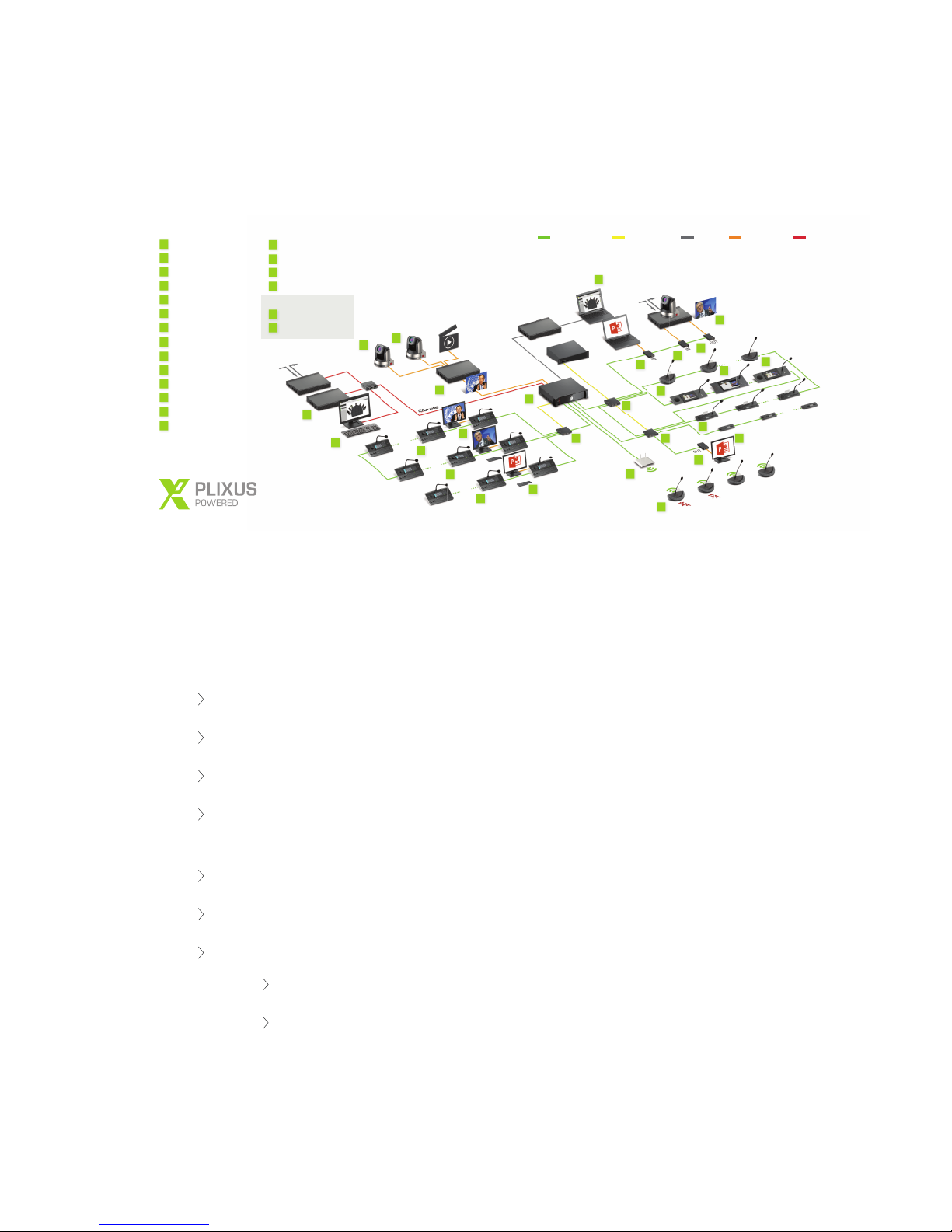
Figure 1-2 Plixus architecture diagram with example setup
The Plixus architecture allows for a mix & match of components: from flushmount devices over multimedia
units and interpreter desk to PTZ cameras and third-party Dante™-enabled applications.
A typical setup consists of the following components:
A central engine (multimedia or audio-only)
CAT 5e network cables
Depending on the size of the network: one or more power supplies.
Depending on the size of the network: one or more network extenders. Each network extender
powers a separate branch. It permits 4 branches or 2 loops.
CoCon management software to manage every aspect of the meeting
T-Rex recording software to record audio
A combination of units
uniCOS units: multimedia flushmount units
Confidea T units: tabletop units (discussion/voting/interpretation)
CO MPO N EN TS 18
Page 19

Confidea F units: flushmountunits (discussion/voting/interpretation)
Confidea G3 units: the wireless solution
Lingua Interpreter Desks
Video IN-OUT boxes
A combination of peripherals
PTZ cameras
External displays
Dante™-enabled devices
CO MPO NEN TS 19
Page 20

COMPONENT RANGE
As discussed earlier, you can include different components in your Plixus network. These components can
be divided into four different categories:
Central equipment: the heart of the Plixus network, with these devices you can set up,
configure and maintain the Plixus network.
Network equipment
Multimedia: these devices support the usage of multimedia during the meeting such as
viewing video on delegate units or video injection / extraction from the Plixus network.
Audio: these units only support receiving and sending audio.
Interpreter equipment:
CO MPO N EN T R A NGE 20
Page 21
PLIXUS MME
Overview
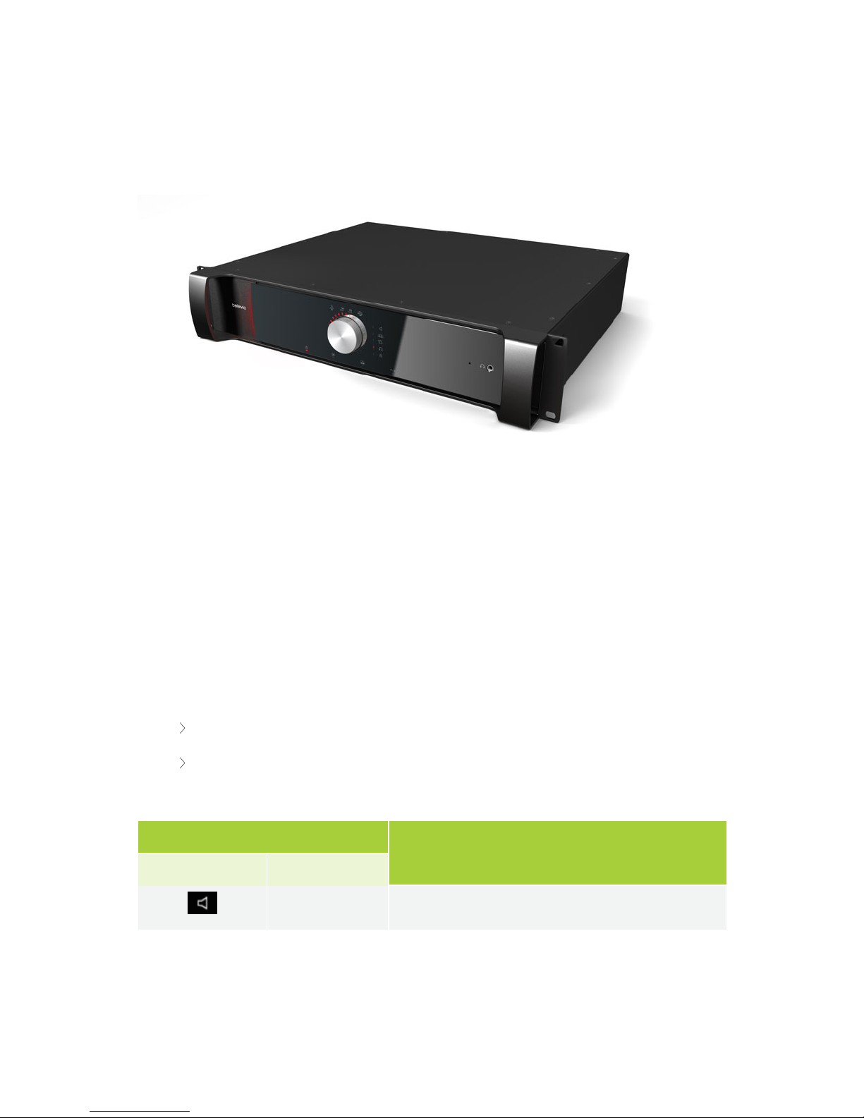
Figure 1-3 Plixus MME front view
The Plixus Multimedia Engine is the heart of the Plixus system. It controls all delegate units and
interconnects to other systems either via the external audio connections or control ports (camera control,
Dante, central software, API).
The central unit can drive a maximum of 80 Plixus units directly from the engine. In case a large number of
units are required, the system can be extended with multiple Plixus Network Extenders.
Control Dial Functionality
The front of the Plixus MME/AE-R has a Jog Wheel with the following options:
Push the dial to select a Level 1 setting
Turn the dial to select a Level 2 setting
The following table details the control dial options:
Level
Function
1 2
0 to max Loudspeaker volume
PL I X U S M ME 21
Page 22
Level
Function
1 2
Microphone mode: Direct access
Microphone mode: Request
Microphone mode: VoX
Microphone mode: Group
0 to 8 Maximum number of open microphones
0 to max Plixus MME headphone volume
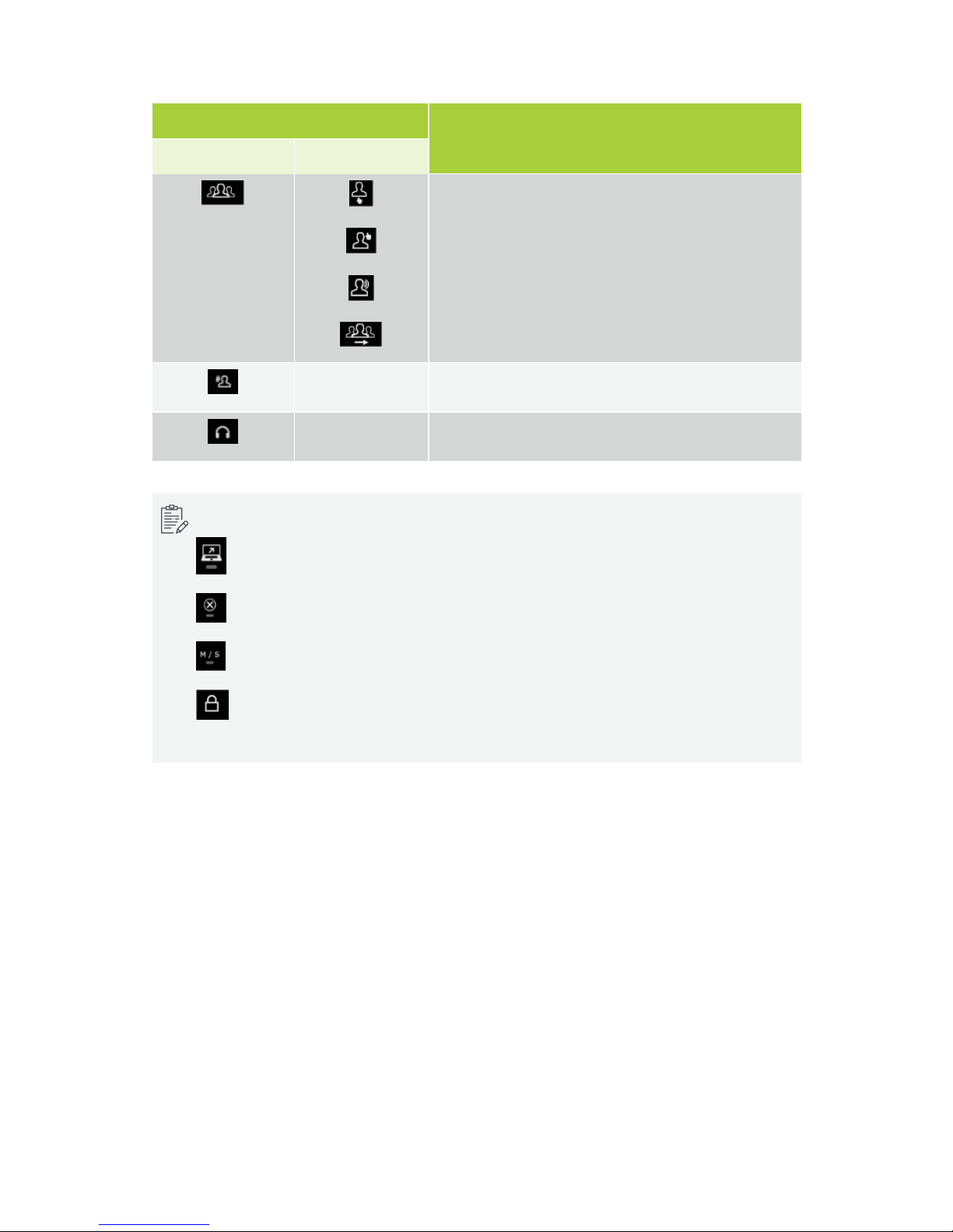
Additional icons are displayed to indicate different states:
indicates that CoCon server is connected to the Plixus Multimedia Engine
indicates an error state.
indicates a Master/Slave setup.
Control button key lock activation/deactivation. Press and hold control dial for 5 sec. You can
still browse through the settings when locked.
PL I X U S M ME 22
Page 23

Rear Connectivity
Figure 1-4 Plixus MME rear view
The rear of the Plixus MME/AE-R has the following connectivity options:
1. AC power inlet & fuse holder
2. Balanced (XLR) and two unbalanced (RCA) audio outputs
3. Balanced and (XLR) two unbalanced (RCA) audio inputs
4. 48 V power output (400W)
5. Two redundant DANTE™ network ports
6. Two USB 2.0 ports (for future use)
7. IP configuration port (LAN)
8. Digital video output (HDMI) (for future usage)
9. SDI video input
10. SDI video output
11. Two back bone conference network ports that are not powered (for future use)
12. Four powered Plixus conference network ports
PL I X U S M ME 23
Page 24
Dante™ Interface
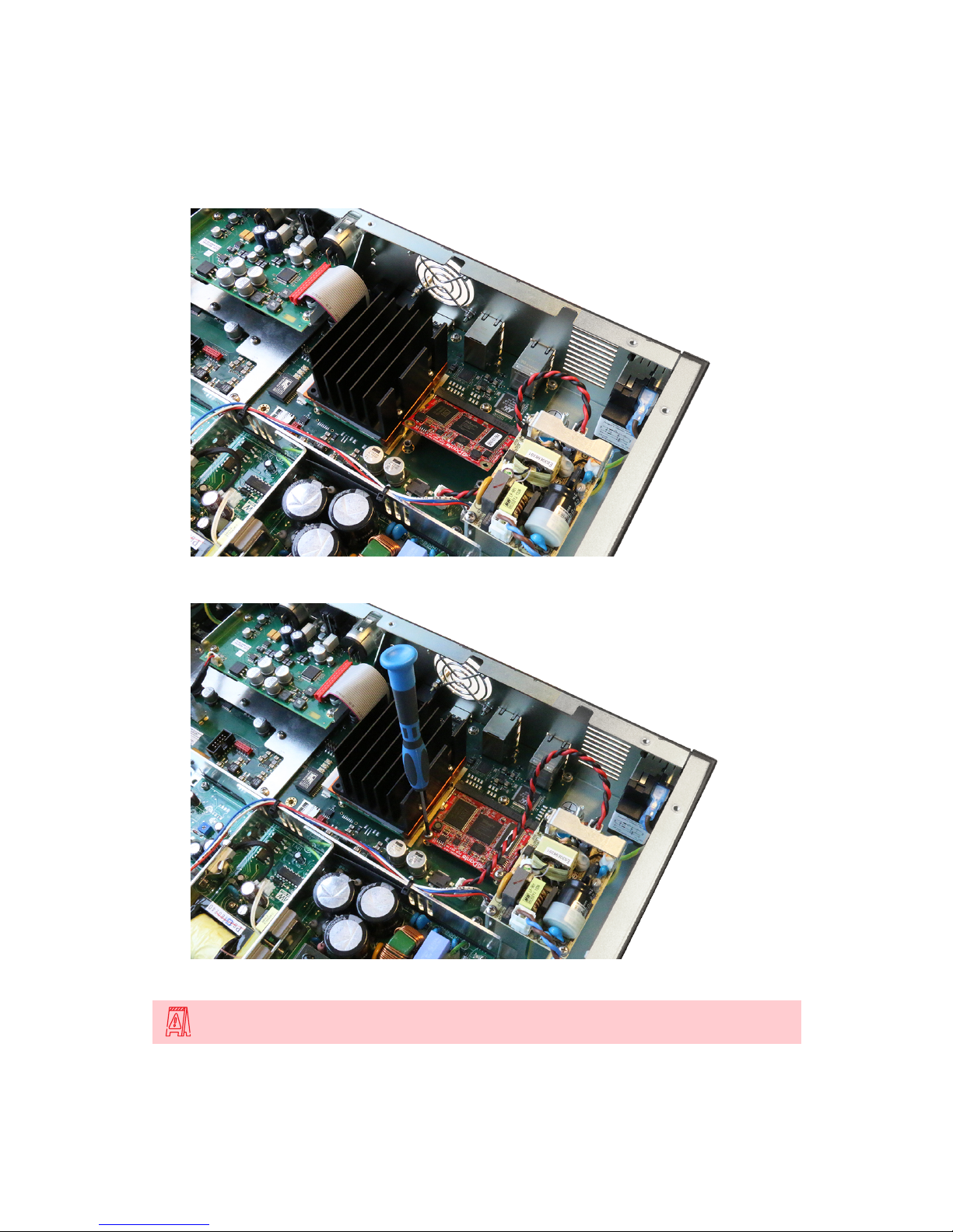
The optional Dante™ card should be installed as follows:
1. Make sure the Dante card connectors face the top and put the card in under a 45° angle.
2. Press the card down and secure it with two screws, one at each corner of the card.
Please switch off power before inserting the DANTE™ card into the Plixus MME/AE-R.
PL I X U S M ME 24
Page 25
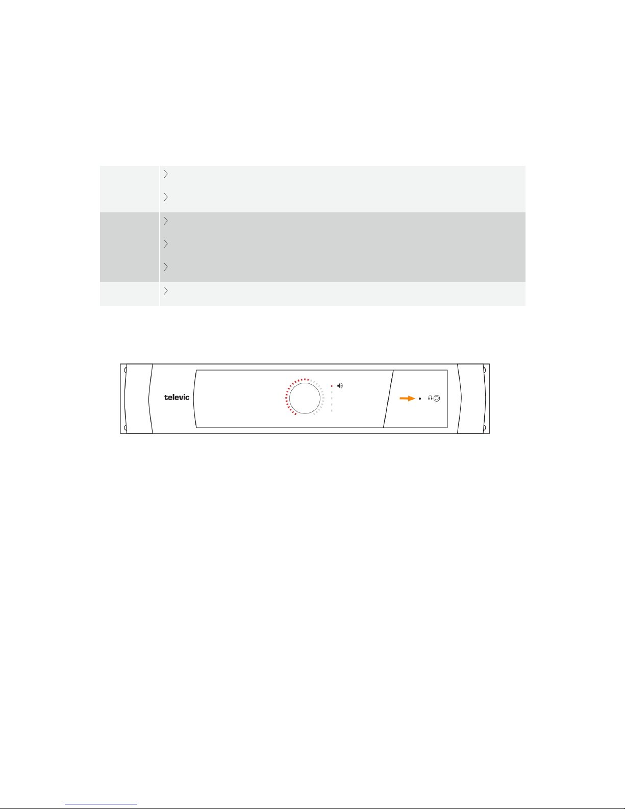
Open the cover of the central unit and insert the card in the position as indicated in the picture. Fix the
Dante™ card by means of two screws and put the cover back on the central unit.
Supported Video Formats
SD SDI
PAL
NTSC
HD SDI
720p: 23.976, 24, 25, 29.97, 30, 50, 59.94 and 60 Hz
1080p: 23.976, 24, 25, 29.97 and 30 Hz
1080i: 50, 59.94 and 60 Hz
3G SDI
1080p: 50, 59.94 and 60 Hz
Factory Defaults Restore Button
Figure 1-5 Reset button on Plixus MME
To restore factory default settings , push the button inside the small hole , next to the headphone connector
for at least 10 sec and release.
PL I X U S M ME 25
Page 26
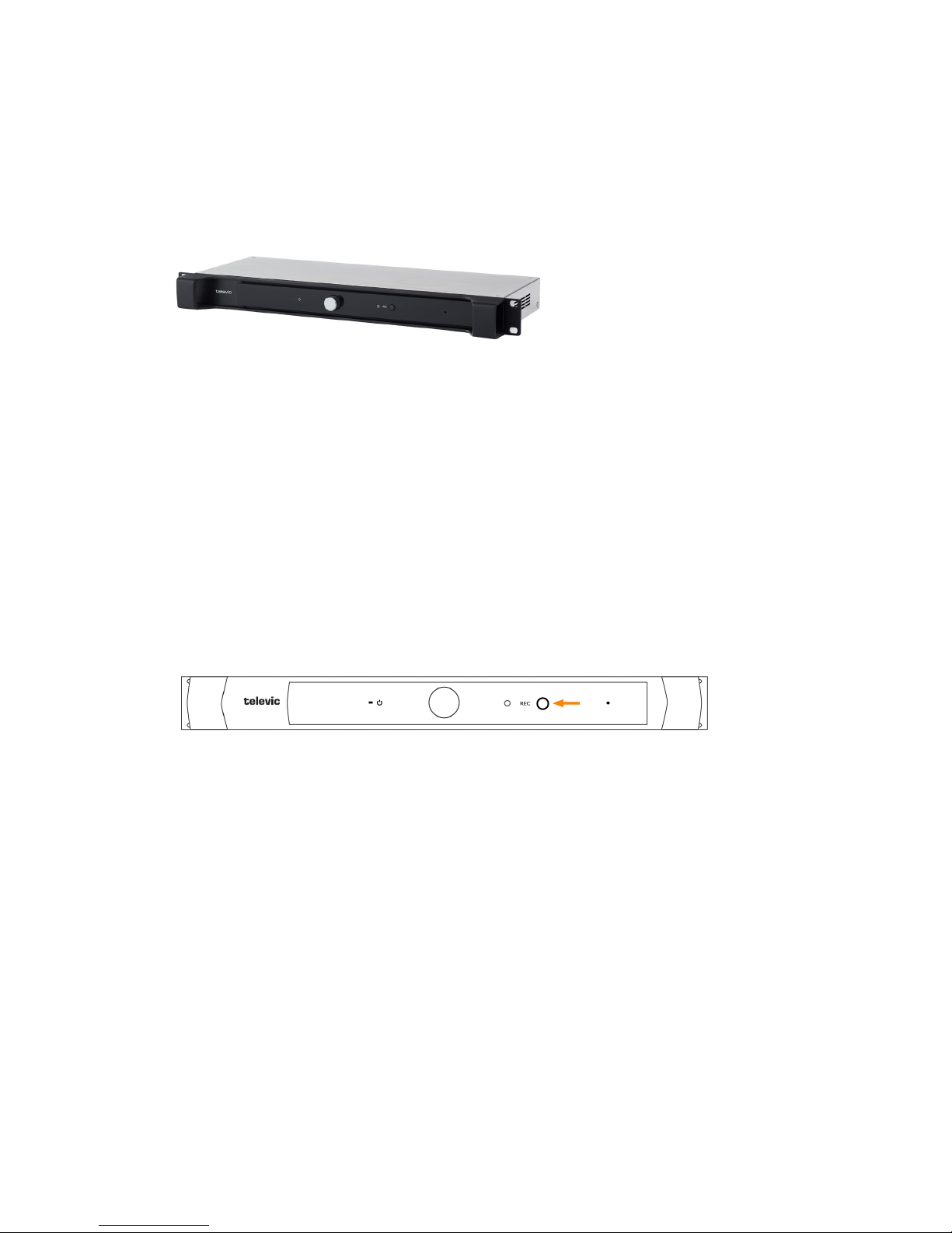
PLIXUS AE-R
Overview
Figure 1-6 Plixus AE-R front view
The Plixus audio engine is a 19" rack mountable device that provides audio processing and signal handling
required for the Plixus network. It controls all delegate units and interconnects to other systems either via
the external audio connections or control ports.
With the volume dial you can adjust the volume and using the record button you can easily start or stop
recording the meeting. In contrast to the multimedia engine the Plixus AE-R does not have an internal
power supply, meaning you will need at least one external power supply.
Recording Feature
Figure 1-7 How to use the recording feature
With the Plixus AE-R you can record the floor and up to three different languages. You can use the button
on the engine or the Plixus Core web server to control recording.
The LED next to the recording button shows the status of recording. The Plixus AE-R has an internal
recording capacity of 8GB. Depending on the selected bitrate you can record over 100 hours of audio. Use
the USB port on the back to expand the recording memory.
You can download all Recorded meetings from the Plixus Core web server. There is an option to configure
different recording features using the web server. See "Recording" on page88 for more information.
PL I X U S A E- R 26
Page 27
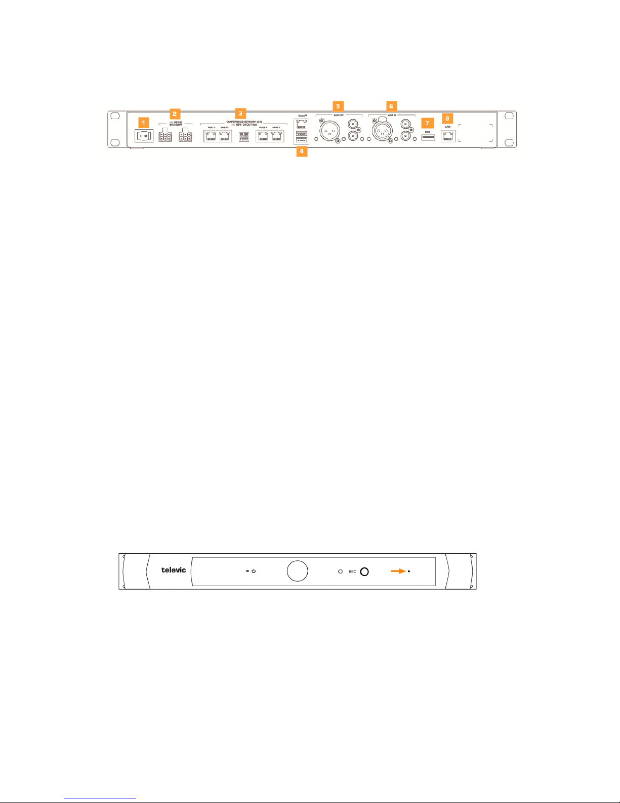
Rear End Connectivity
Figure 1-8 Back view of Plixus AE-R
1. On/off switch
2. Two power connectors for power supply injection
3. Plixus conference ports
4. Two redundant Dante™ network ports
5. Balanced (XLR) and two unbalanced (RCA) audio outputs
6. Balanced (XLR) and two unbalanced (RCA) audio inputs
7. USB 2.0 port to plug in USB device for audio recording
8. LAN port
Power Supply
The Plixus AE-R does not have an internal power supply. By default one external power supply of 220W is
delivered together with the engine. You can use a second power supply for redundancy. However for larger
setups you need the additional power to power the units, preventing you to use the second power supply for
redundancy. See "Power supply design" on page51
Factory Defaults Restore Button
Figure 1-9 Reset button on Plixus AE-R
To restore factory default settings , push the button inside the small hole , next to the headphone connector
for at least 10 sec and release.
PL I X U S A E- R 27
Page 28
PLIXUS POWER SUPPLY
The Plixus MME has an internal power supply of 48V/10A(480W). However the Plixus AE-R does not. By
default you receive one Plixus power supply with the AE-R. When the internal power supply of the MME or
the external power supply of the AE-R is insufficient, a separate power supply is necessary.
For more information on how many power supplies your system requires see "Power supply design" on
page51.
Plixus AE-R Power Supply
In contrast to the MME the Plixus AE-R doesn't have an internal power supply. By default the Plixus AE-R
comes with one external power supply.
Plixus Power Supply
The power supply is a 19" rack mount version. The front panel is equipped with a rocker mains switch with
built-in indicator and two mains fuses.
The use of an additional power supply is needed when the internal power supply of the Plixus MME/AE-R is
insufficient.
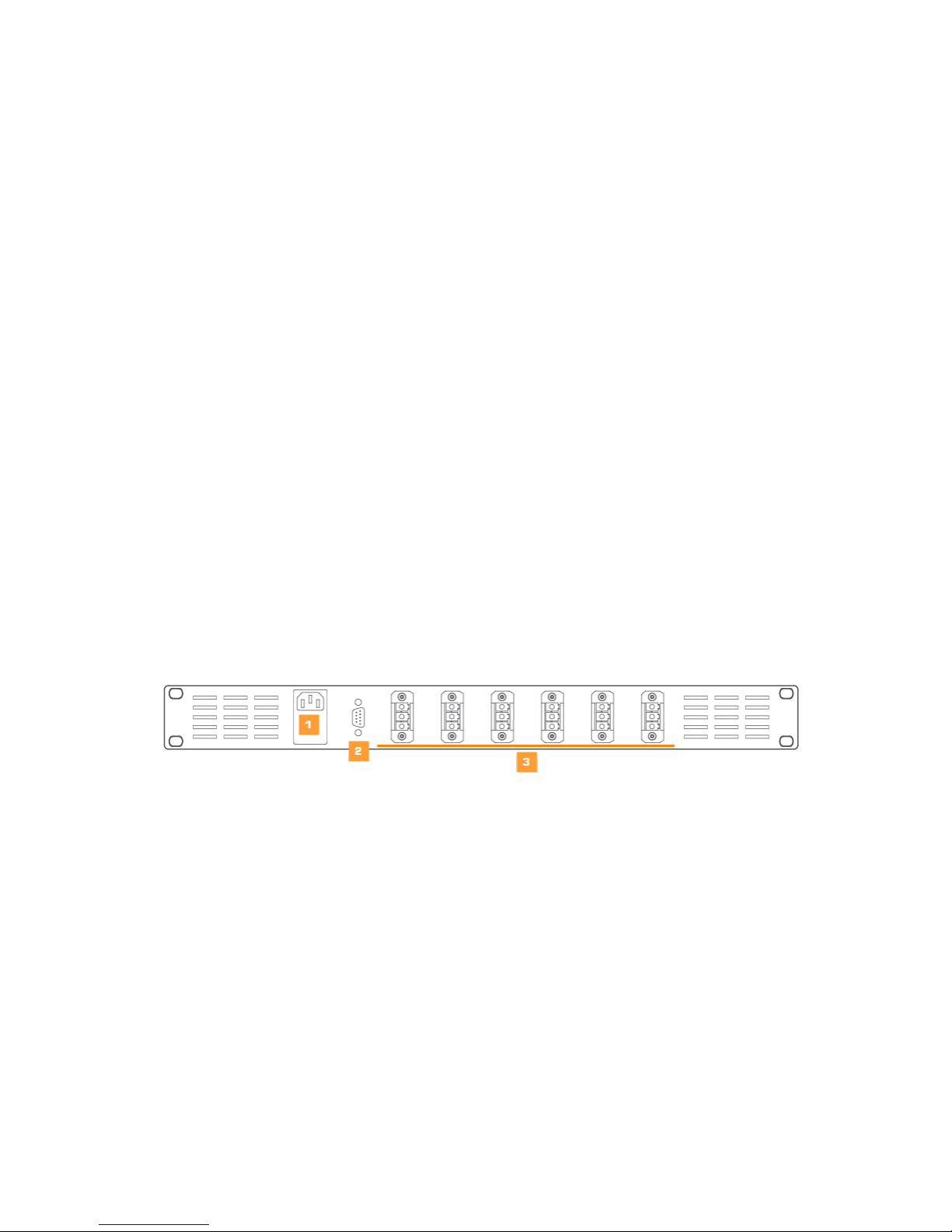
The 230 V mains is connected to the power supply through a male connector (1) at the back of the power
supply. A power good TTL output on a D9 connector (2) allows you to check whether the power is okay. Six
female Phoenix connectors (3) are available to branch off the 48 V.
Figure 1-10 Rear power supply connections
PL I X U S P O W ER SU PP L Y 2 8
Page 29
PLIXUS NEXT
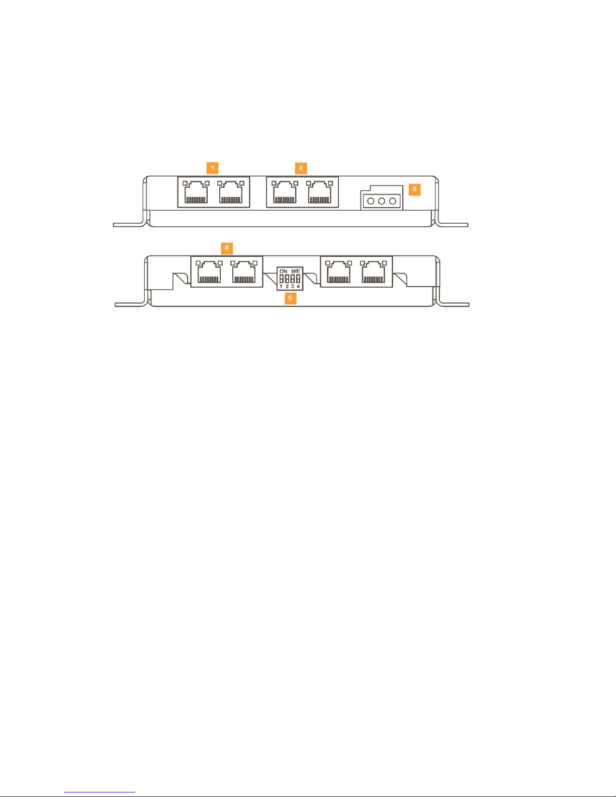
Plixus NEXT is the next generation of Plixus network extenders which have the same functionality and
connectivity, but additionally offer the option to configure (via DIP switches) a delayed power up of the
conference extension ports (see DIP switch table below).
1. Two Plixus network conference ports (uplink).
a. Gives Plixus network signal to conference extension ports of the central engine or other
network extender.
b. Allows connection in branch / loop.
2. LAN ports are not used.
3. 48V power supply: powers the four conference ports.
4. Four Plixus network conference ports (downlink).
5. DIP switches enable / disable power of conference ports and allow sequential startup.
PL I X U S N EX T 29
Page 30

DIP Switch Table
DIP switch
settings
Ports powered
at startup
Startup delay
of first port(s)
Port interval(s) Remark
1 1 1 1 All ports 0 0 Standard settings
0 0 0 0 None NA NA
No power, only data.
Switches activated after startup,
will power corresponding ports
1 0 0 0 Port 1 0 NA 1 port powered
0 1 0 0 Port 1 + 2 0 0.5 2 ports powered
1 1 0 0 Port 1 + 2 + 3 0 0.5 3 ports powered
0 0 1 0 All ports 0 0.5 delay 0 to 1.5
1 0 1 1 All ports 2 0.5 delay 2 to 3.5
0 1 1 0 All ports 4 0.5 delay 4 to 5.5
1 1 1 0 All ports 6 0.5 delay 6 to 7.5
0 0 0 1 All ports 8 0.5 delay 8 to 9.5
1 0 0 1 All ports 10 0.5 delay 10 to 11.5
0 1 0 1 All ports 12 0.5 delay 12 to 13.5
1 1 0 1 All ports 14 0.5 delay 14 to 15.5
0 0 1 1 All ports 16 0.5 delay 16 to 17.5
1 0 1 1 All ports 18 0.5 delay 18 to 19.5
0 1 1 1 None NA 0 Remote control*
*planned for future releases
General Network Extender Guidelines
The maximum distance between the central unit and the first Plixus network extender or
delegate unit in the branch is 100 m.
The maximum distance between two Plixus network extenders is 100m.
PL I X U S N EX T 30
Page 31
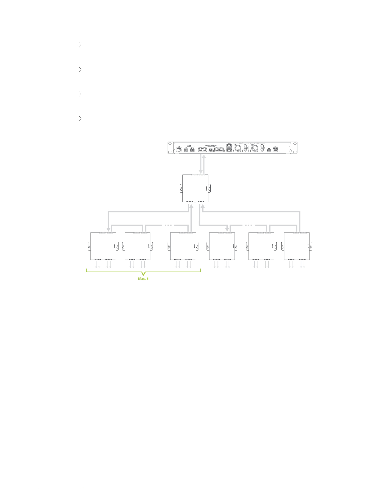
The Plixus network extender must be powered externally (through power supply of Plixus MME
or Plixus power supply).
One branch or loop cannot consist out of more than 8 Plixus network extenders (for optimized
packet propagation)
One branch or loop may consist of no more than 20 Plixus devices (less if power is limiting
factor).
Restrict a downlink port branch to 1 network speed: 100 Mbit or 1 Gbit!
Figure 1-11 Example network extender configuration
Redundancy
In Plixus it is possible to insert a type of fail-safe mechanism by creating redundancy. You can get
redundancy by inserting loops in your network. When there is a loop, Plixus can still access the device using
a different route when a cable or a device in one side of the loop breaks.
PL I X U S N EX T 31
Page 32
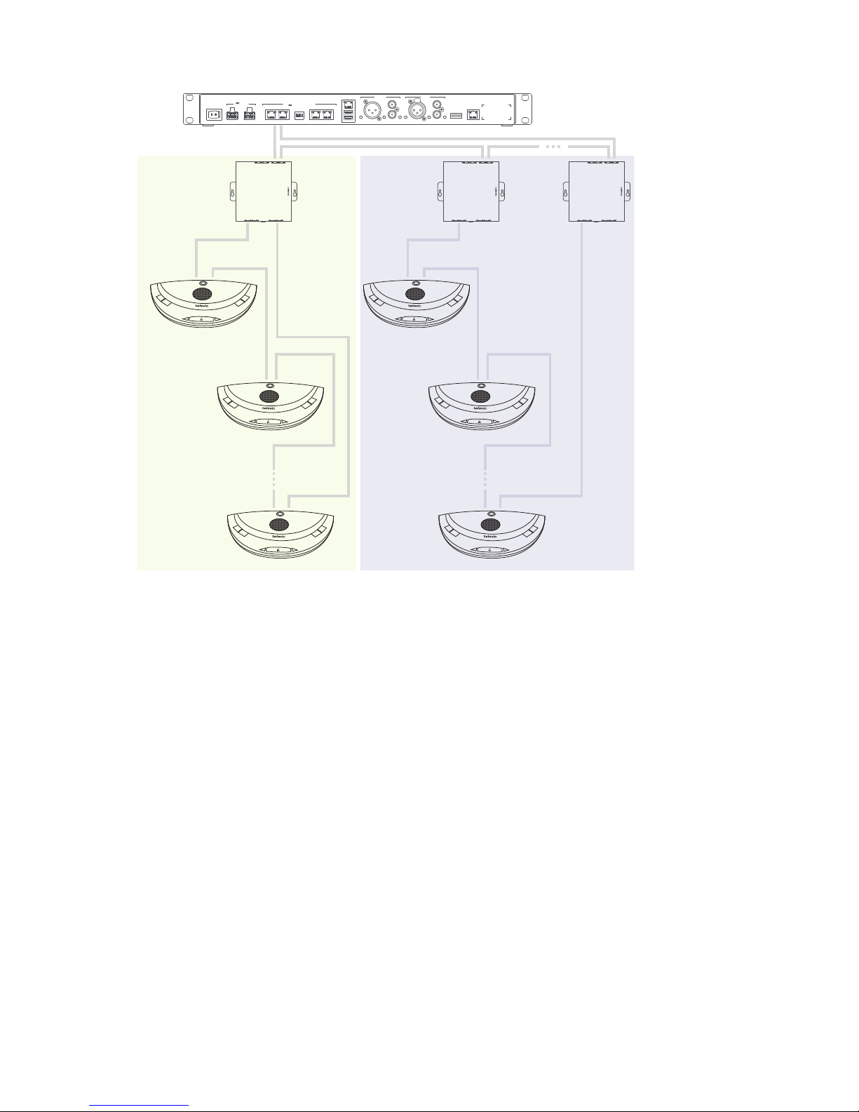
Central
Unit
Network
Extender
Delegate
Unit
Redundancy for cables and
delegate units
Redundancy for cables, network extenders
and delegate units
Dante
TM
LAN
USB
PORT 1
1
ON WE
23 4
PORT 2 PORT 3 PORT 4
CONFERENCE NETWORK (CN)
48 V / 2A OUT (4x)
AUX OUT
AUX IN
48 V IN
MAX 420W
Figure 1-12 How to create redundancy using a netwotk extender.
PL I X U S N EX T 32
Page 33
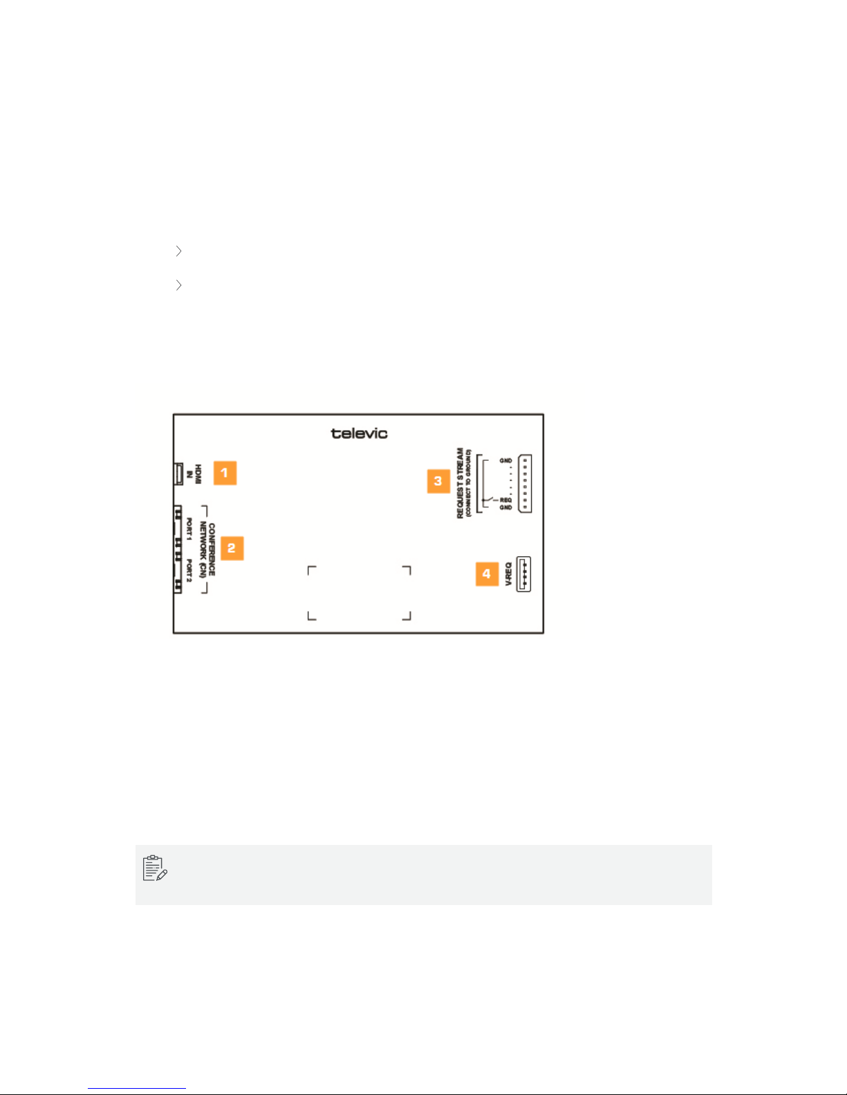
VIDEO IN
Video-In Box
Through the Plixus Video-IN (V-IN) box you can insert a HDMI video stream anywhere in the Plixus network.
There are two modes available for the V-IN box:
Fixed routing
Push to show
You can use multiple V-IN boxes in a Plixus network. Group V-IN boxes in order to create a presentation
stream based on a push to show principle (using the Video-Request button or dry contacts). A total of six
streams can be active in the Plixus network at any given time.
Figure 1-13 Video-IN box
1. Insert HDMI video stream
2. Two Plixus conference ports
3. Dry contacts for video stream input request
4. USB connection to V-REQ
The USB connection for the V-REQ is not a standard USB connection. This connection only works
for the V-REQ.
V ID EO I N 33
Page 34
The V-IN box supports the following formats:
1920×1080p60
1920×1080p30
1280×720p30
Interlace is not supported
Video Request
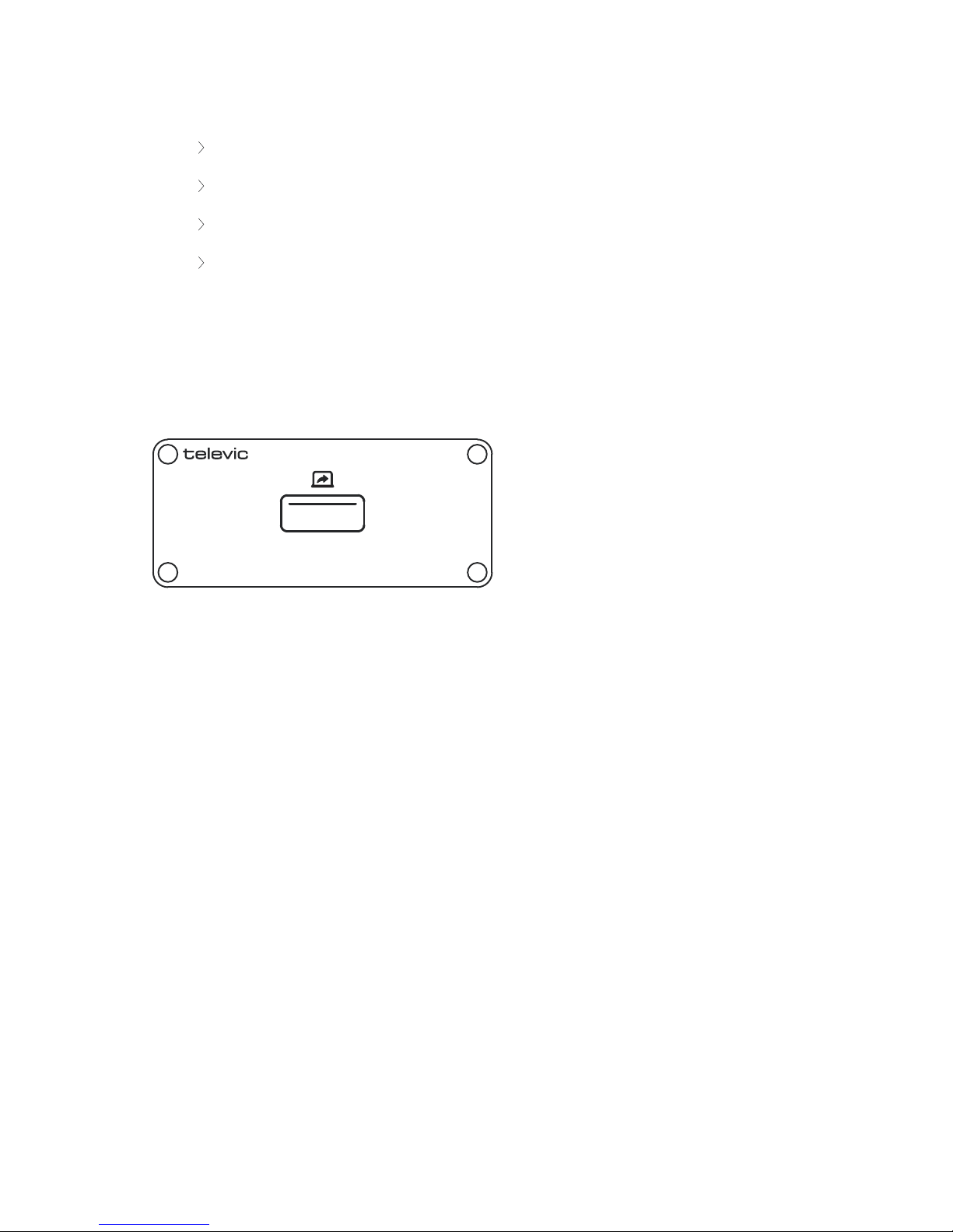
The video stream input request can be done via dry contacts or by using the Plixus V-REQ (video input
request button), see image below.
Connection of V-REQ to the Video In Box is done through the included micro USB cable.
Figure 1-14 Video-Request button
V ID EO I N 34
Page 35
VIDEO-OUT
Video-Out Box
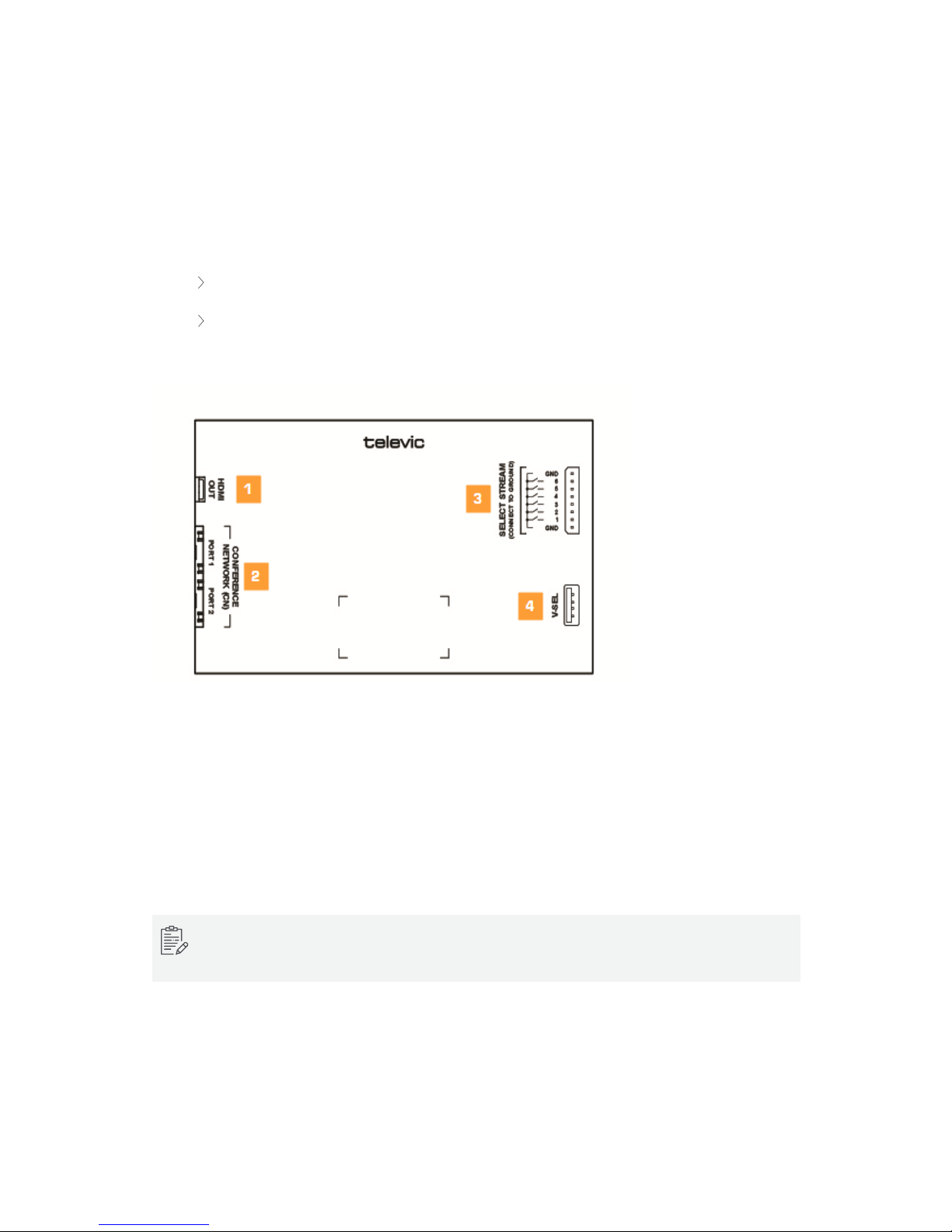
You can use the Plixus Video-OUT Box to extract any HDMI video stream from the Plixus network to an
external device using HDMI. Two modes are available:
fixed stream routing
selection of available streams (using Video-Selection (V-SEL) or dry contacts)
You can assign multiple V-OUT boxes to a group, routing a specific stream to these boxes.
Figure 1-15 Video-OUT box
1. HDMI OUT connection
2. Two Plixus conference ports
3. Dry contacts for video stream selection (six streams available)
4. USB connection for V-SEL
The USB connection for the V-SEL is not a standard USB connection. This connection only works for
the V-SEL.
The V-OUT box supports the following formats:
V ID EO - O U T 35
Page 36
Supports all resolutions with a maximum of 1920×1080p60
Interlace is not supported
Video Selection
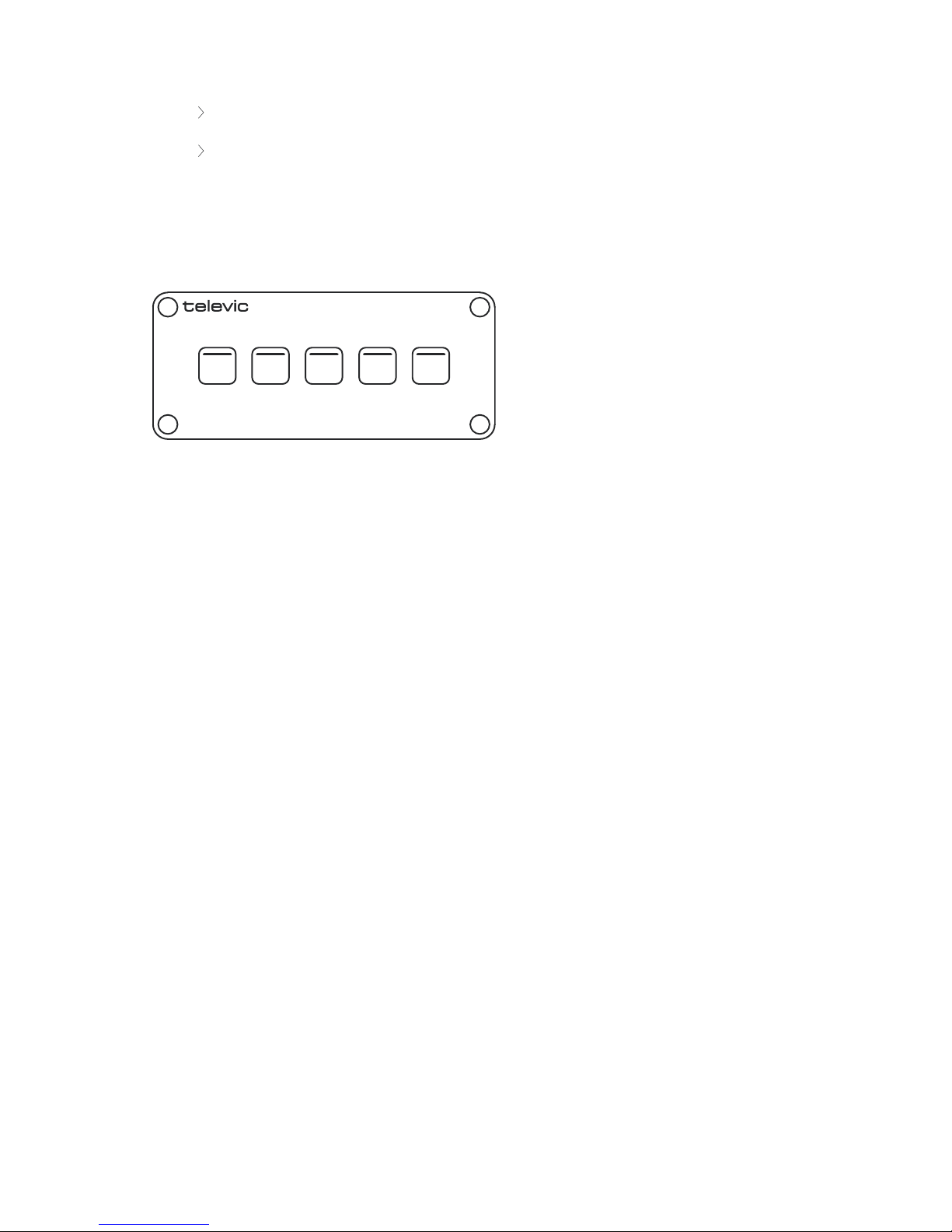
Video stream selection can be done via dry contacts or by using the Plixus V-SEL accessory. Connect the V-
SEL to the Video-OUT Box is done through the included micro USB cable.
21
3
4
5
Figure 1-16 Plixus V-SEL accessory
V ID EO - O U T 36
Page 37
VIDEO STREAM ROUTING
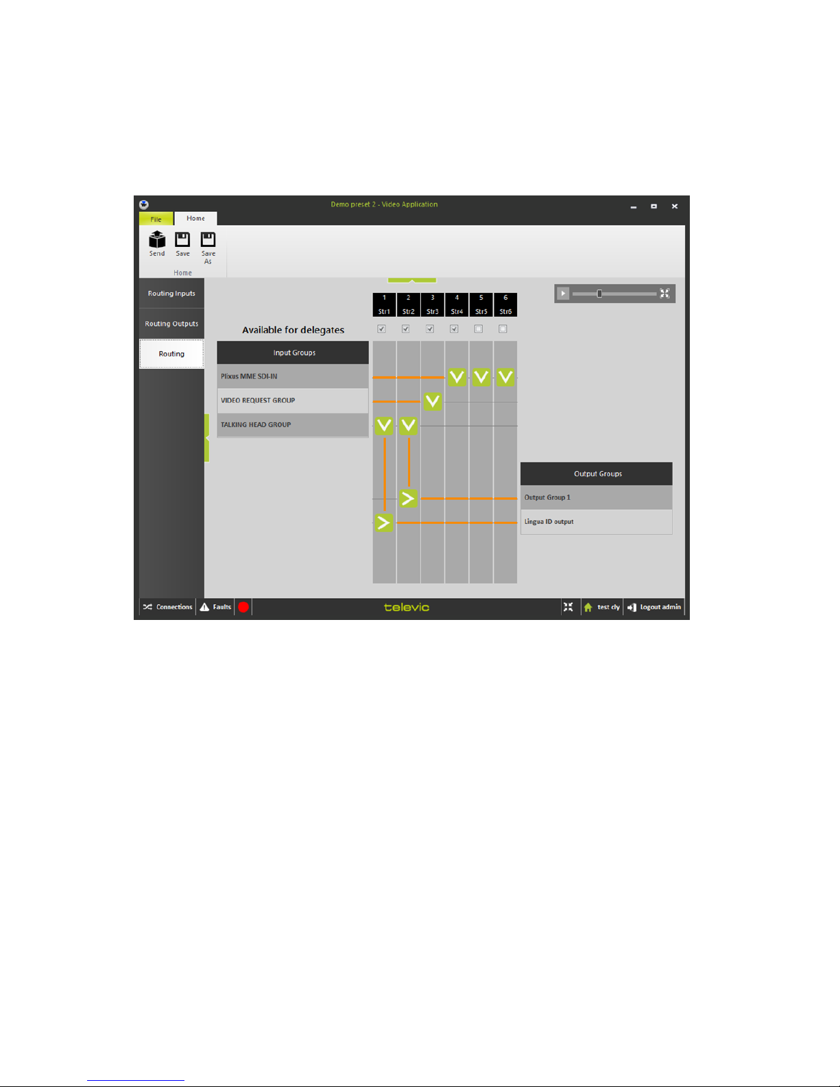
You can configure video stream routing using the CoCon Video application (CoCon & Plixus CRP version ≥
5.0).
Figure 1-17 Configure video stream routing in CoCon
In the application you can define the video input and create input groups ( shown on the left side of the
figure). In the middle you can see the six available video streams, you can change the name of each of
these streams. Disable streams by unchecking the option Available for delegates, these streams will not
be available for the V-SEL.
Assign a specific input to one or more streams, the downwards arrow indicates that the input is put on that
video stream. The output is shown on the right side, the arrow pointing to the right indicates that the video
stream is connected to the output.
See CoCon user guide for more information.
V ID EO S TRE AM R O U TI NG 3 7
Page 38

DELEGATE EQUIPMENT
You can add different types of units and other peripherals to your Plixus architecture depending on your
requirements. Below you can find a list of all delegate equipment that you can combine with Plixus together
with a short description.
Audio Only Equipment
Product Description
Confidea (tabletop or
flushmount)
The audio only unit of the Plixus network.
Lingua interpreter desk Unit specifically designed to support interpretation. This unit only supports
audio.
Multimedia Equipment
Product Description
uniCOS (7" or 10") The touch screen multimedia unit. Allows delegates and chairmen to see additional
information, video, but also documents that are relevant for the meeting or the
agenda.
For more information on how to use these different peripherals consult their dedicated user guides. How to
set them up in the Plixus network is explained in the chapter "Installation design" on page40.
DE L EGAT E EQUIPMENT 38
Page 39

INTERPRETER EQUIPMENT
Within the Plixus network it is possible to configure interpretation. Different units are availble for
interpreters. Below you can find a list of all these units, together with a short description.
Product Description
Lingua interpreter desk
(video enabled)
Unit specifically designed to support interpretation. In the video enabled version you
can extract video from the units HDMI output.
Lingua Interpreter desk
(Audio)
Unit specifically designed to support interpretation, that does not support video.
IN TER PRE TER EQ UIPMENT 39
Page 40

INSTALLATION DESIGN
This chapter describes how to set up the installation of the Plixus network before
you can physically install it. You will find more information on the technical details
of the different components and how to combine and configure them.
Page 41
PLIXUS COMPONENT PROPERTIES
It is not possible to combine all Plixus components on the same branch because some units are powered
over the Plixus cable, while others require external power.
In addition there is a difference in network speed for audio-only devices versus multimedia devices. As a
consequence, three different categories of devices are possible that you cannot mix on the same branch.
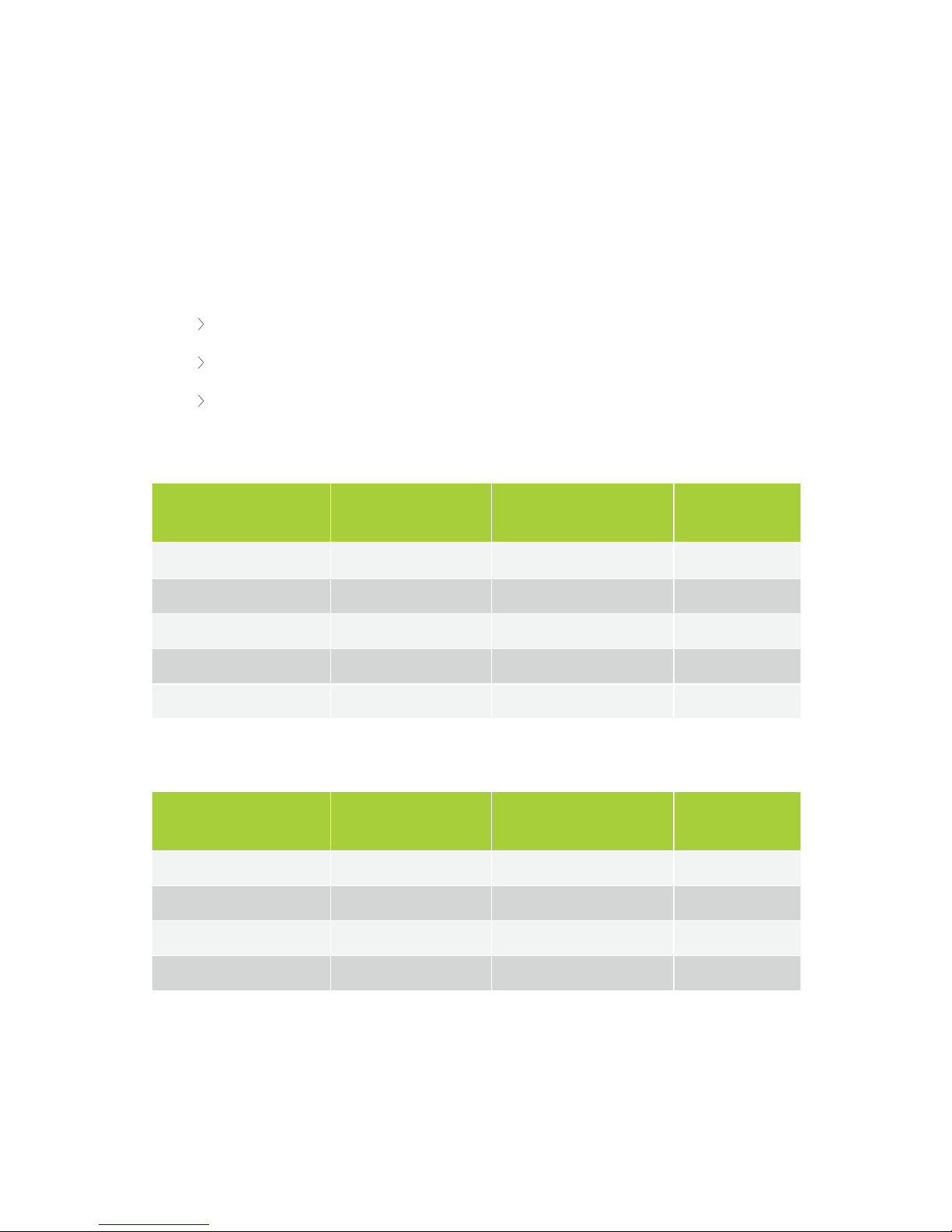
The following tables list the properties of all components. Please note the different categories:
100 Mbit powered over Plixus Cable
1 Gbit powered over Plixus Cable
1 Gbit externally powered
100 Mbit Powered Over Plixus Cable
Component type Plixus Network Speed Power over Plixus cable
Max Power
Consumption
Confidea F 100Mbit
+
5 W
Confidea T 100Mbit + 5 W
Confidea CS 100Mbit + 2 W
Lingua ID (audio only) 100Mbit + 11 W
Confidea G3 WCAP 100Mbit + 10 W
1Gbit Powered Over Plixus Cable
Component type Plixus Network Speed Power over Plixus cable
Max Power
Consumption
Lingua ID (video) 1Gbit + 12 W
Confidea F-DIV-C 1Gbit + 12 W
Video Out Box 1Gbit + 7 W
Video In Box 1Gbit + 7 W
PL I X U S C O MPO N ENT P R O PER TIES 41
Page 42
1Gbit Externally Powered
Component type Plixus Network Speed Power over Plixus cable
Max Power
Consumption
uniCOS 7" F/ MM 1Gbit - 15 W
uniCOS 10" F/MM 1Gbit - 15W
Plixus NEXT 100Mbit / 1Gbit - 7 W
A branch cannot mix products with different network speeds. A single branch is
restricted to components from one and the same category.
Figure 1-18 Dos and don'ts of combining units
PL I X U S C O MPO N ENT P R O PER TIES 42
Page 43

It is strongly recommended to only place Plixus Network Extenders in one branch, and not to mix
them with uniCOS Multimedia units (although they belong to the same category).
PL I X U S C O MPO N ENT P R O PER TIES 43
Page 44

GENERAL INSTALLATION GUIDELINES
The following installation design rule apply for one branch / loop powered only by the Plixus engine (internal
48 Vdc power supply) or an external Plixus Power Supply:
A maximum of 100 W
A specific maximum of devices per product family per branch / loop
A maximum cable length between two units of 100 m
Units Per Branch / Loop
Depending on the type of unit we advise to add a maximum amount of devices per branch. This is to ensure
that the last device in the branch receives enough power (only for devices powered over Ethernet) and limit
delay data transmission.
In the table below you can see the maximum allowed devices per branch.
Device type Max. number per branch
Confidea T/F 20
Confidea F channel selector 30
uniCOS F/MM 30
Lingua Interpreter Desk 8
uniBox 30
Video IN / OUT 8
Plixus NEXT 8
Confidea G3 WCAP 8
Confidea F-DIV-C 8
When To Use A Network Extender
When the four Plixus conference ports provided by the engine are insufficient for your system, you can
extend your range by using network extenders (Plixus NEXT). A network extender has four additional
conference ports, which allows you to add much more units to your network.
GEN ERAL IN ST ALL ATION G U ID ELIN ES 44
Page 45

There a two possible configurations to use these network extender, you can daisy-chain them or put them in
a tree structure. When you daisy-chain network extenders you can use a maximum of 32 extenders (eight
per branch and this for the four Plixus conference ports). In a tree structure there are no limitations. See
"Installation diagram" on the next page for a schematic representation of these cases.
GEN ERAL IN ST ALL ATION G U ID ELIN ES 45
Page 46
INSTALLATION DIAGRAM
Configuration With Plixus Engine Only
televic
POWER48vDC
PORT 1 PORT 2 PORT 3 PORT 4
CONFERENCE NETWORK (CN)
48 V / 2A OUT (4x)
Plixus Engine
Room Equipment
Plixus Power Supply
FLOOR MICROPHONE MUTE
! " # $ % & '
FLOOR MICROPHONE MUTE
! " # $ % & '
FLOOR MICROPHONE MUTE
! " # $ % & '
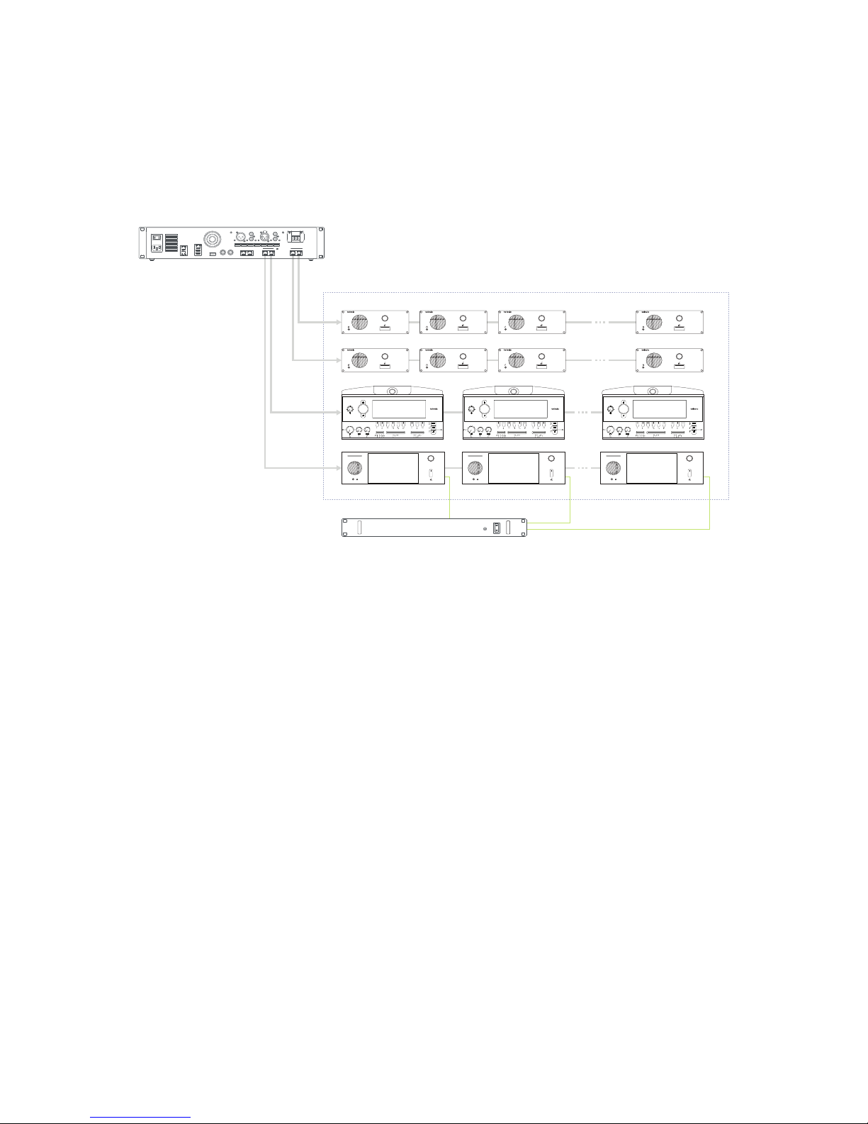
Figure 1-19 Example of Plixus network with engine only
For a setup where you only need an engine, connect the units directly to the conference ports of the Plixus
engine. Daisy chain the different units in the branch. If your system contains uniCOS units, you need an
external power supply.
Only mix compatible units in one branch. For more information on which units you can combine see "Plixus
component properties" on page41. In this table you can also see the power consumption, which you need
to know how many units you can have in one branch. Use the power calculator tool to validate your
configuration ("Power supply design" on page51).
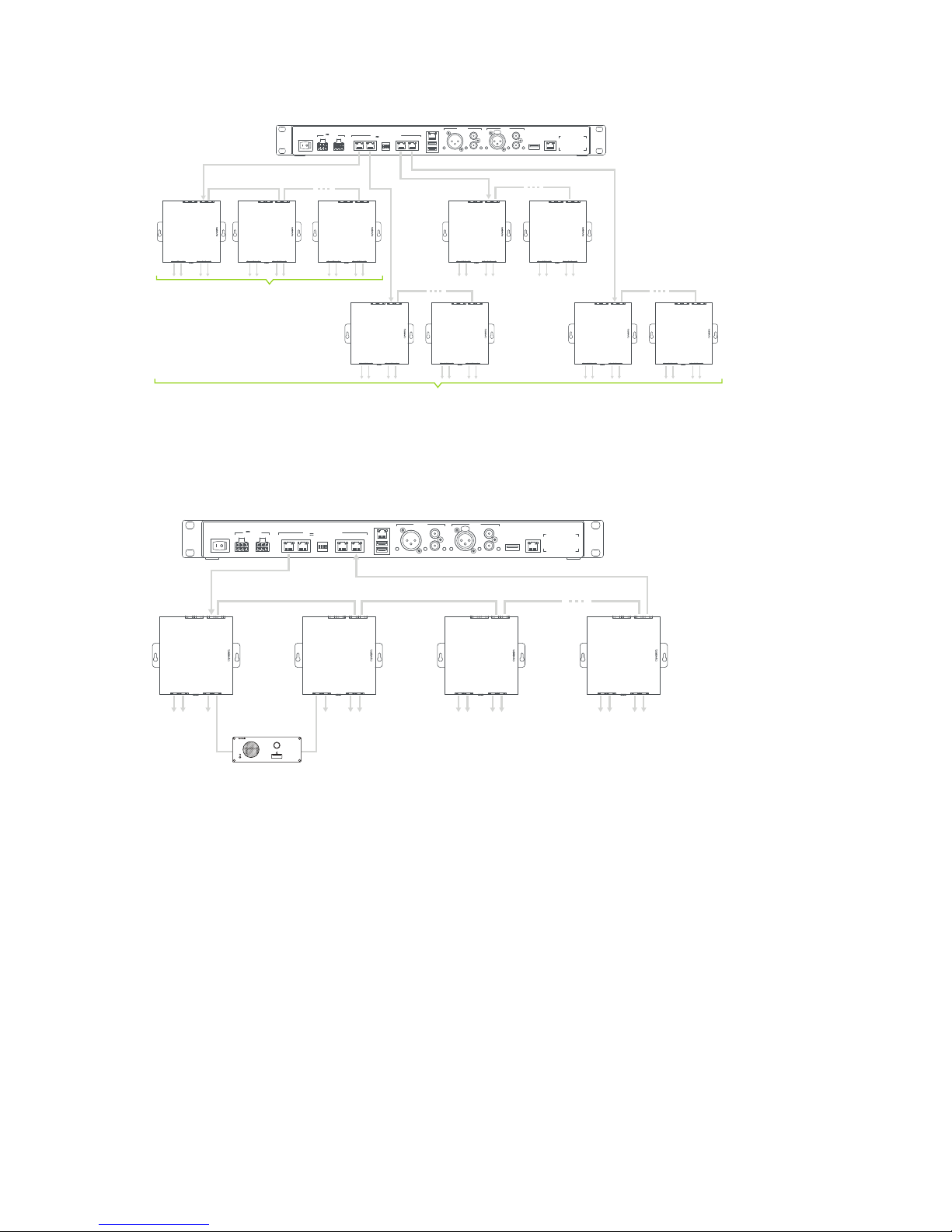
Configuration With Network Extender
DAISY-CHAIN NETWORK EXTENDERS
When you daisy-chain network extenders, you can have a maximum of 32 network extenders ( eight per
branch and this forthe four Plixus conference ports).
IN STA L L ATIO N D IA G R A M 46
Page 47
Dante
TM
LAN
USB
PORT 1
1
ON WE
23 4
PORT 2 PORT 3 PORT 4
CONFERENCE NETWORK (CN)
48 V / 2A OUT (4x)
AUX OUT
AUX IN
48 V IN
MAX 420W
Max. 8
Max. 32
Figure 1-20 How to put network extenders in daisy-chain configuration
To create redundancy in your system you can insert loops (see "Plixus NEXT" on page29
Dante
TM
LAN
USB
PORT 1
1
ON WE
23 4
PORT 2 PORT 3 PORT 4
CONFERENCE NETWORK (CN)
48 V / 2A OUT (4x)
AUX OUT
AUX IN
48 V IN
MAX 420W
Figure 1-21 Plixus network with daisy-chained network extenders and loops
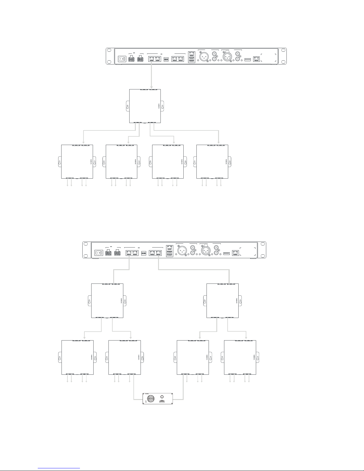
TREE STRUCTURE OF NETWORK EXTENDERS
For larger setups you can put the netwok extenders in a tree structures. Here there is no limitation on the
amount of network extenders you can put in the tree.
IN STA L L ATIO N D IA G R A M 47
Page 48
Dante
TM
LAN
USB
PORT 1
1
ON WE
2 3 4
PORT 2 PORT 3 PORT 4
CONFERENCE NETWORK (CN)
48 V / 2A OUT (4x)
AUX OUT
AUX IN
48 V IN
MAX 420W
Figure 1-22 How to use network extenders in a tree structure
You can also create redundancy in a tree structure, the figure below shows you how to achieve this.
Dante
TM
LAN
USB
PORT 1
1
ON WE
2 3 4
PORT 2 PORT 3 PORT 4
CONFERENCE NETWORK (CN)
48 V / 2A OUT (4x)
AUX OUT
AUX IN
48 V IN
MAX 420W
IN STA L L ATIO N D IA G R A M 48
Page 49
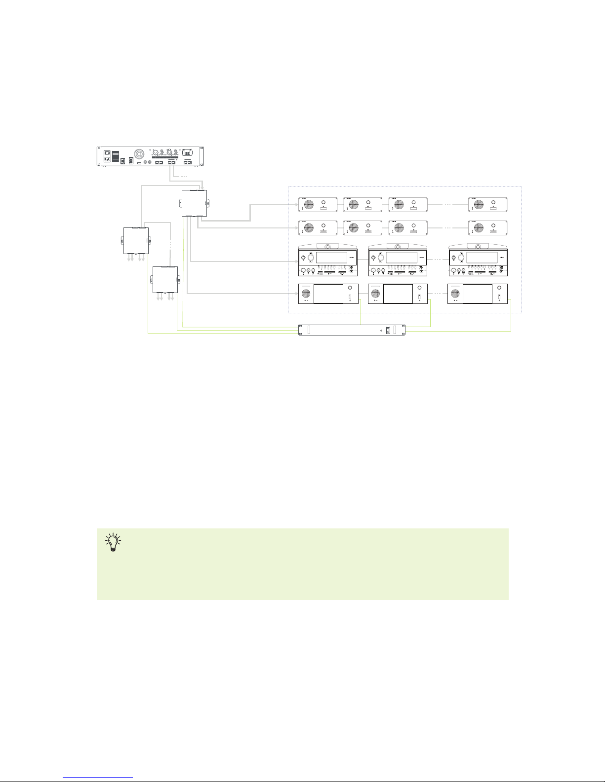
Figure 1-23 Plixus network with network extenders in tree structure and with loops
PLIXUS SETUP WITH NETWORK EXTENDERS
televic
POWER48vDC
PORT 1 PORT 2 PORT 3 PORT 4
CONFERENCE NETWORK (CN)
48 V / 2A OUT (4x)
Plixus Engine
Room Equipment
Room
Equipment
Room
Equipment
Plixus Power Supply
Max. 800 W / Power Supply
48 V
FLOOR MICROPHONE MUTE
! " # $ % & '
FLOOR MICROPHONE MUTE
! " # $ % & '
FLOOR MICROPHONE MUTE
! " # $ % & '
Figure 1-24 Example of Plixus network with network extenders
For installation with a network connector, use the conference port on top of the network extender to
connect with the Plixus engine. Use the second top conference port to form a daisy chain with another
network extender. Use the conference ports on the bottom of the extender to connect the units inside the
room. To connect the extender to the units the same principles apply as for the direct connection of the
engine to the units. See "Configuration with Plixus engine only" for more information.
The network extender and uniCOS units require an external power supply. There is a maximum of power
that the power supply can foresee. Use the power calculator tool to see how many power supplies you
require ("Power supply design" on page51).
The Plixus AE-R does not have an internal power supply and comes with one power supply of
220W by default. Check the table with power consumption details and use the power calculator
tool to check how many power supplies you need. You can find more information on the power
needed for your system in "Power supply design" on page51.
IN STA L L ATIO N D IA G R A M 49
Page 50
Examples
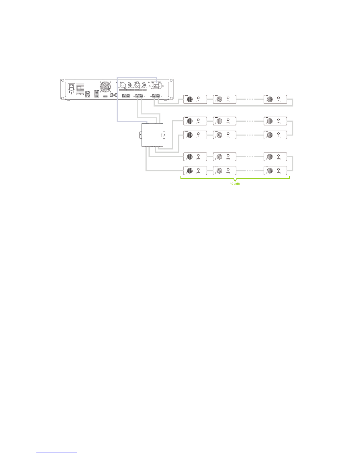
EXAMPLE WITH 50 CONFIDEA F UNITS
IN STA L L ATIO N D IA G R A M 50
Page 51
POWER SUPPLY DESIGN
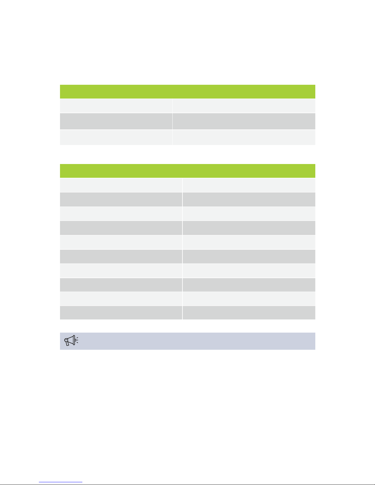
Power Availability And Consumption Table
Power availability
Plixus MME total power supply 500W (400W available for Plixus ports
Plixus AE-R power supply 220W
One single Plixus port allows 100W (engine ports or extension ports)
Maximum power consumption
Confidea F/T 5W
Confidea CS 2W
uniCOS 7" 15W
Plixus NEXT 7W
Lingua Interpreter Desk - Audio only 11W
Lingua Interpreter Desk - Video 12W
Video-IN / Video-OUT box 7W
Confidea WCAP 10W
Maximum distance between units 100m (signal regenerated in every unit)
Minimum required voltage per unit 36V
The general rule states that you should use a maximum 20 delegate units per branch / loop.
Plixus AE-R Power Supply
The Plixus AE-R does not have an internal power supply, however it does have two power connectors. By
default you get one power supply together with the engine. You can extend this power supply with another
as redundancy or when the system requires more power.
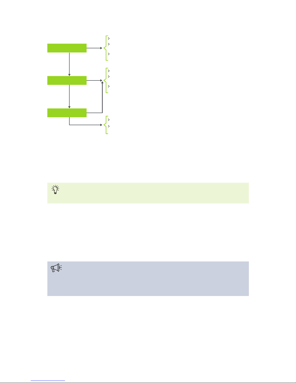
To check how many power supplies you require, consult the flowchart shown below.
PO W ER SUP PLY D ESI G N 51
Page 52
Plixus NEXT needed?
More than 40 units?
More than 200 W?
Plixus AE-R (71.98.2902)
Plixus Power Supply (71.98.2930)
required for network extender
Plixus AE-R Power Supply (71.98.2931)
for power redundancy
Plixus AE-R (71.98.2902)
Plixus AE-R Power Supply (71.98.2931)
to power units
2 x DIN Rail Power Supply 48 Vdc - 10 A
for power redundancy
Plixus AE-R (71.98.2902)
Plixus AE-R Power Supply (71.98.2931)
for power redundancy
No
Yes
Yes
Yes
No
No
Figure 1-25 How to decide to need an additional Plixus AE-R power supply
Calculator Tool
The Plixus Power Calculator Tool allows to you to validate a configuration in more detail. It takes
into account the network cable lengths, power cable lengths and the different types of equipment.
The Plixus Power Calculator Tool can be easily found on the Televic Partner Domain.
Regardless of the calculator values, the maximum values above still apply. If more units, more power or a
larger length is needed, then you need to create a separate branch using a Network Extender.
Cable Requirements
Televic advises to use minimum CAT 5e F/UTP 23 AWG for run cables and CAT 5e F/UTP 24
AWG patch cables.
Televic strongly advises that cables for all video-enabled products are created in loop.
Please follow the cable guidelines described here, they are important to guarantee correct system
performance.
PO W ER SUP PLY D ESI G N 52
Page 53

Keep all cable runs under 90% of the maximum distance supported for each media type as
specified in the relevant standard. This extra headroom is for the additional patch cables that
will be included in the end-to-end connection.
Always use the same type of cable (except AWG) in the end-to-end connection.
Cabling installations and components should be compliant with the ISO/IEC 11801 standard.
Do not stress the cable by doing any of the following
Applying additional twists
Pulling or stretching beyond its specified pulling load rating
Bending it beyond its specified bend radius
Creating tension in suspended runs
Stapling or applying pressure with cable ties
Avoid placing copper cables near equipment that can generate high levels of
electromagnetic interference. Generally avoid locations near power cords, fluorescent lights,
building electrical cables and fire-prevention components.
Use the Plixus Power Calculator to ensure sufficient power for all units in the network.
PO W ER SUP PLY D ESI G N 53
Page 54
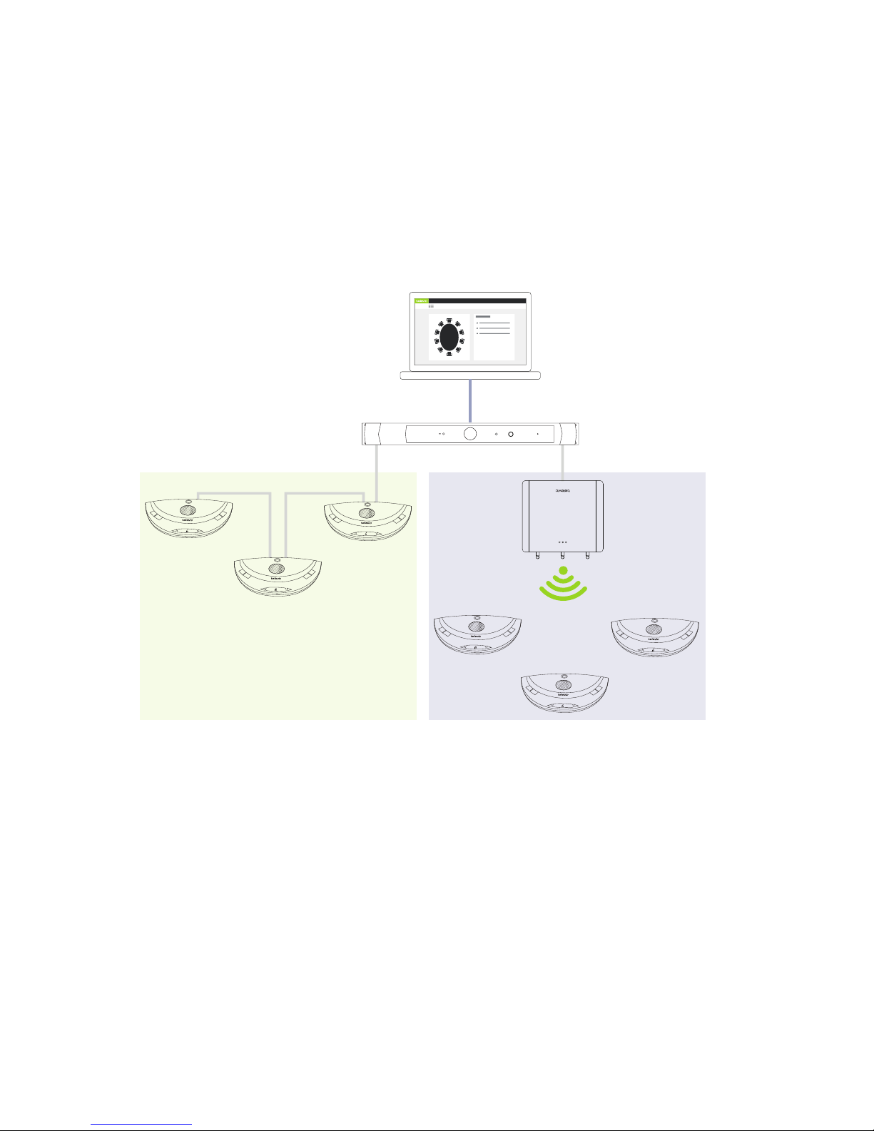
COMBINE PLIXUS WITH CONFIDEA G3
Combine Wired And Wireless Units
With Plixus it is possible to combine wired and wireless units this can be the case when disabled people
require a wireless microphone. You can also use the wireless units to extend the amount of people that can
join the meeting. A third reason to combine wired and wireless, is to use the wireless system as backup.
televic
REC
Wired Wireless
Figure 1-26 How to combine wired and wireless units in a single Plixus setup
CO MBI NE PL IX US W ITH CO N F ID EA G 3 54
Page 55
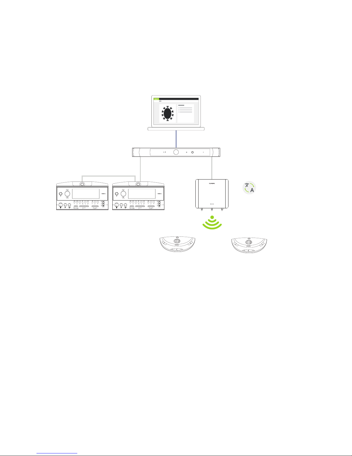
Combine Interpretation With Wireless Units
In the Confidea G3 unit product range, multiple units that can support that support channel selection are
available. Couple such units with the Plixus engine to receive the channels from the Lingua Interpreter
Desks in your Plixus network.
televic
REC
Interpretation
over RF
FLOOR MICROPHONE MUTE
! " # $ % & '
FLOOR MICROPHONE MUTE
! " # $ % & '
Figure 1-27 How to distribute languages using radio frequency
CO MBI NE PL IX US W ITH CO N F ID EA G 3 55
Page 56
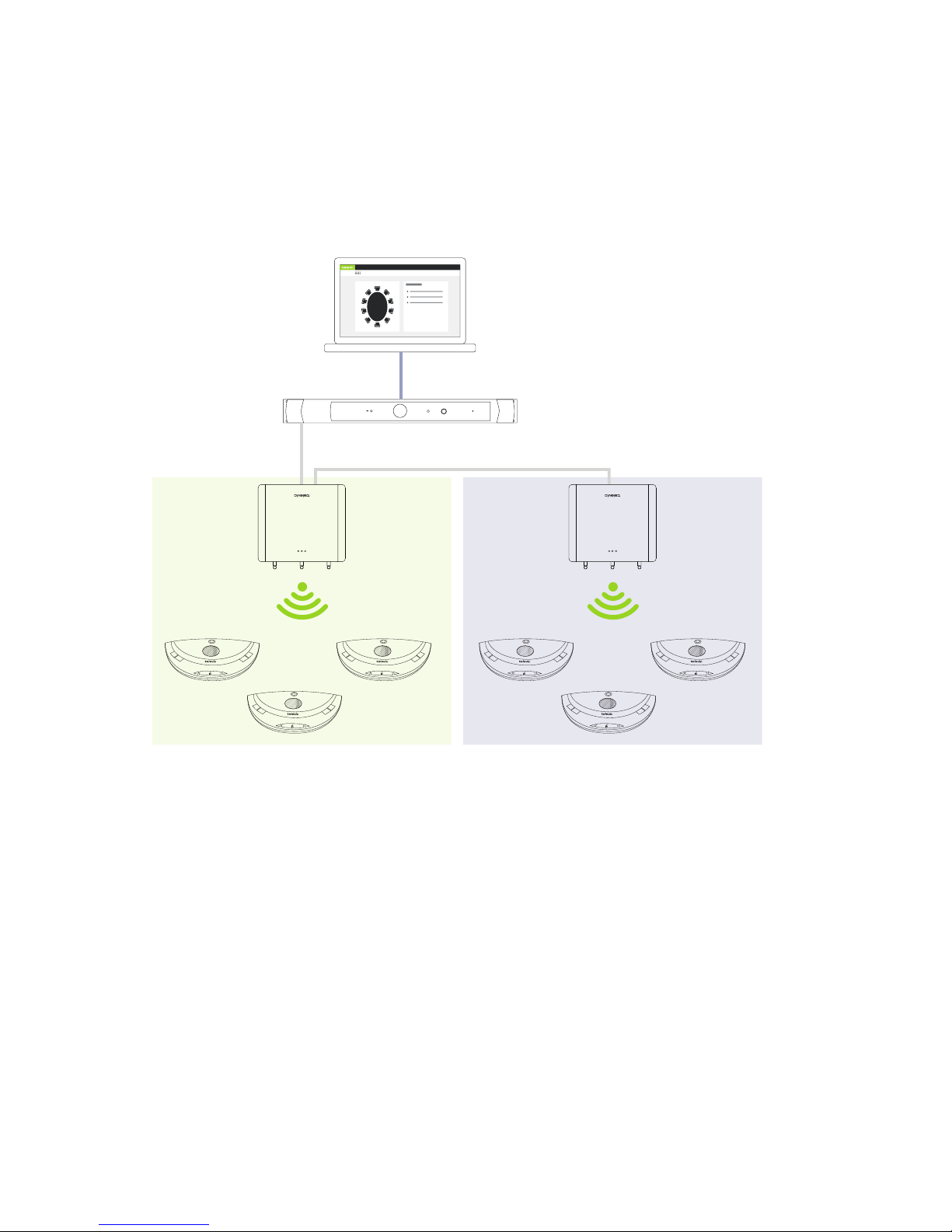
Range Extension With Multiple Access Points
Improve the range of your room by using multiple WCAPs. By using multiple WCAPs you are able to
connect to much more units spread out over the entire meeting room. Formore information on how to
position the WCAPs for optimal transmission see the Confidea G3 dedicated user guide.
televic
REC
WCAP 1 RF range WCAP 2 RF range
Figure 1-28 Improve the range of your system by using multiple WCAPs
CO MBI NE PL IX US W ITH CO N F ID EA G 3 56
Page 57
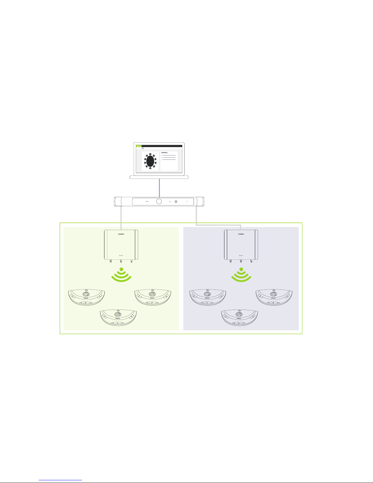
Split And Combine Rooms
Use the WCAP in standalone mode for small meetings. For larger meetings you can combine multiple
rooms by coupling the WCAPs with the Plixus engine. In this way you can manage all units centrally using
the Plixus engine and web server.
When you need to split the room again, simply uncouple the WCAP from Plixus. The WCAP will go back to
standalone mode where it remembers all its previous settings.
The Plixus engine will remember the WCAPs once they were coupled. Just couple them using the web
server whenever you need to combine rooms.
WCAP 1 Standalone
WCAP 1 & 2 combined in Plixus
WCAP 2 Standalone
televic
REC
Figure 1-29 Use the WCAPs in standalone mode when you need to seperate rooms or combine to rooms into
one by coupling the WCAPs to the Plixus network.
Create Redundancy
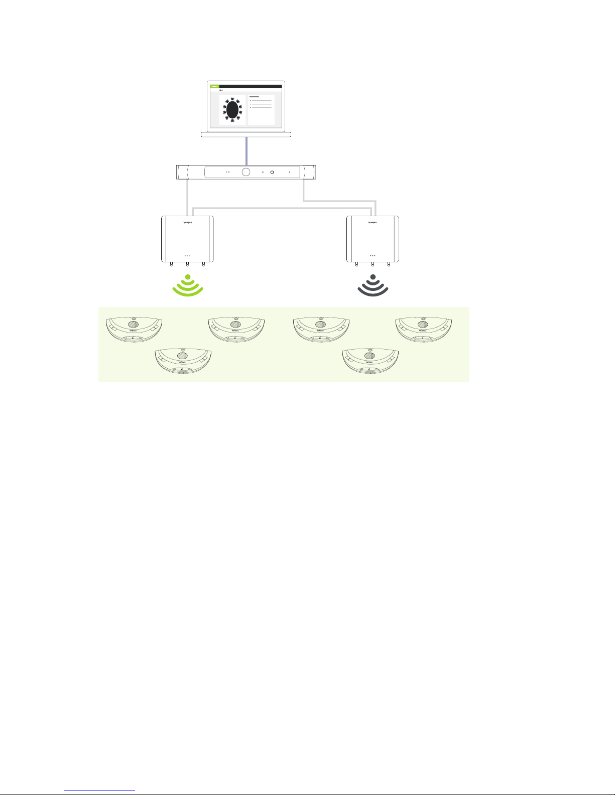
Use multiple WCAPs to create redundancy. When one WCAP fails you can easily switch to associated units
to another empty WCAP using the web server. See "Couple with Confidea G3" on page105
CO MBI NE PL IX US W ITH CO N F ID EA G 3 57
Page 58
WCAP 2 without
associated units
Units associated
with WCAP 1
televic
REC
Use web server to transfer
units to backup WCAP
in case of problems
Figure 1-30 Create redundancy by having a backup WCAP in your Plixus system with no associated units.
Transfer units in case of problems to this backup WCAP by using the Plixus Core web server.
CO MBI NE PL IX US W ITH CO N F ID EA G 3 58
Page 59

INSTALLATION PROCESS
This chapter describes how to physically set up and install the Plixus network. Here
you can find all technical details needed to correctly install all Plixus components.
Page 60

INTRODUCTION
Before you start, make sure to take all necessary precautions. Refer to the tables above and ensure
all components are installed and sufficiently powered.
Before you install the Plixus system, make installation design as described in "Installation design" on
page40 to ensure correct installation. In this design you will calculate the following elements:
The system Power consumption
The amount of external power supplies needed
Cable length needed
IN TRO DUCT IO N 60
Page 61
POWER SUPPLY
Power UniCOS Units And Network Extenders
To supply power to the uniCOS units or network extenders, 48VDC is required. A WAGO Power Connector
supplies the necessary power. It is advised to use strain reliefs (see: Figure ). Note that each power
connector has 2 x 3 contacts which allows daisy chaining of units.
When connecting the power cables, please note the correct order of the cables and their
corresponding colors, see the picture above.
Power Supply Of The Central Unit
When connecting power at the back of the central engine, please note the correct order of the
cables and their corresponding colors
PLIXUS AE-R
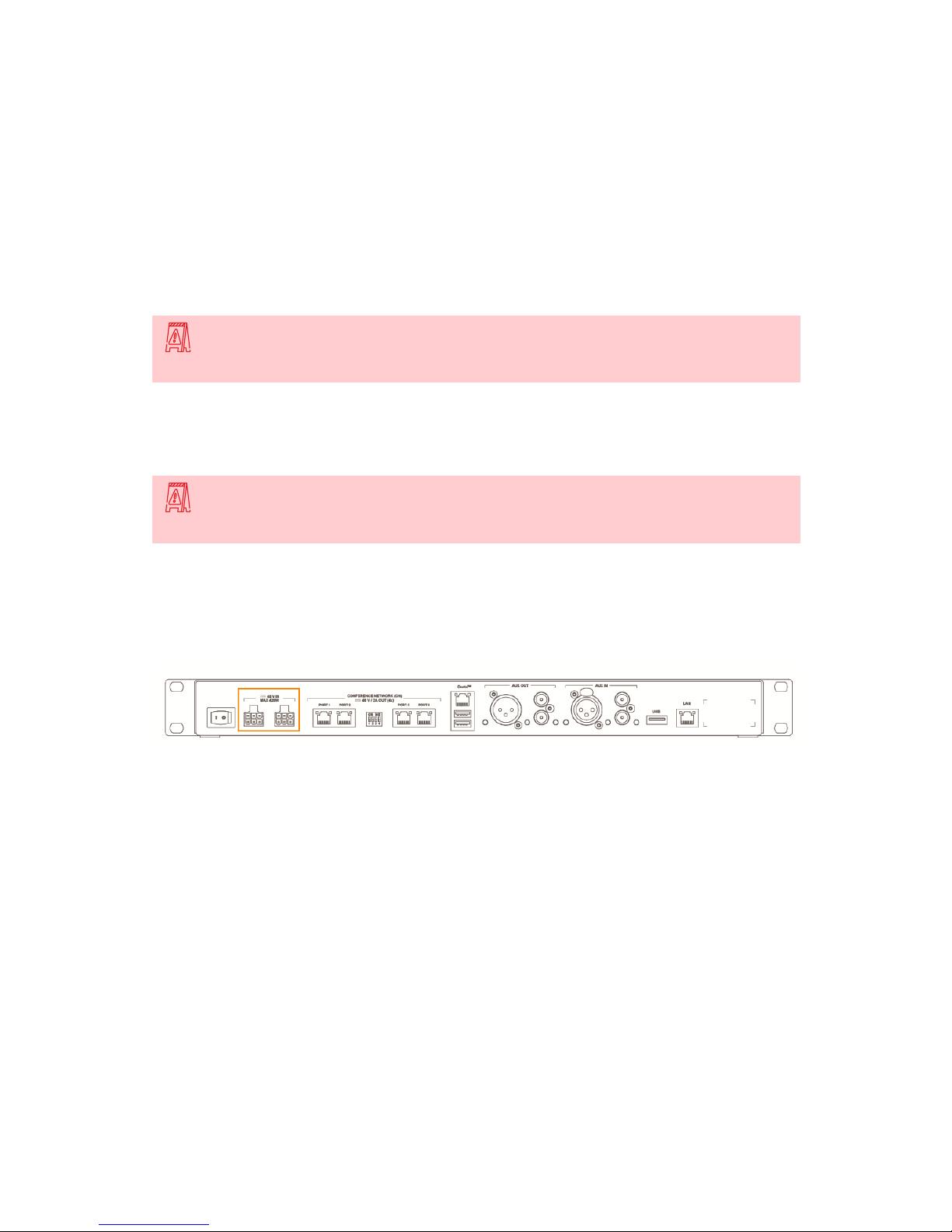
To supply power to the Plixus AE-R using the power outlets on the engine. You can add two 220V power
supplies. Use a second one when 220V is insufficient or as a redundant power supply.
Figure 1-31 How to supply power to the Plixus AE-R
PLIXUS MME
The Plixus MME has an internal power supply. To supply power to the units using the Plixus MME put the
cables in the correct order:
1. Blue cable = 0V
2. Green / yellow cable= earth
3. Brown cable = 48VDC
PO W ER SUP PLY 61
Page 62
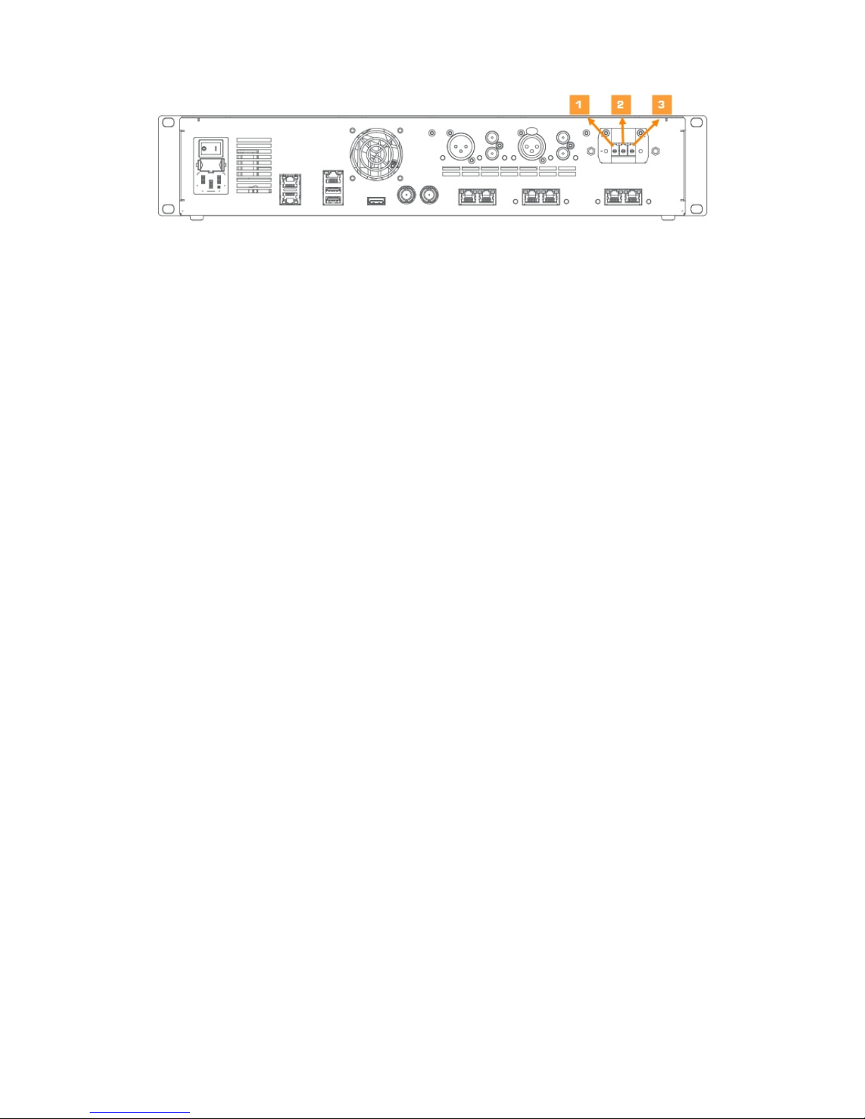
Figure 1-32 Power connection of Plixus MME
You can supply power the units over Ethernet. Each conference ports can supply a maximum of 100W.
PO W ER SUP PLY 62
Page 63

INSTALL CABLES
Use CAT 5e cables to connect Plixus AE-R or MME to the delegate and chairmen units, and to connect the
different units in a branch / loop. For more information on cable details, see "Cable requirements" on
page52.
Televic has standard pre-made cables available in different lengths:
YPC/2 2 m
YPC/5 5 m
YPC/10 10 m
YPC/20 20 m
The voltage level at the output of the central unit is 48 V. A voltage drop is caused by the length of the cable
and the number of units. The last unit of the branch should receive at least 36 V.
IN STA L L CABLES 63
Page 64

INSTALL MICROPHONES
General Microphone Characteristics
All Plixus compatible units have a screw-lock connector to insert pluggable microphones.
The recommended speaking distance from the mouth to the top of the microphone is between 20 to 40cm.
In order to accommodate the variety of speakers and speaking distances, microphones are available in
three different lengths: 30cm (D-MIC30SL), 40cm (D-MIC30SL) and 50cm (D-MIC50SL).
Technical Microphone Characteristics
Parameter Specifications
Material Brass
Color Matt black, RAL 9011
Transducer principle Back electret (condenser)
Operating principle Pressure gradient
Polar pattern Unidirectional
Nominal conditions
Bias resistor = 1k2
Vdd = 3.3 VDC
SPL = 1Pa
Max SPL @ 1 kHz 110dB SPL (1% THD+N)
Signal to noise ratio > 67dB(A)
Free field sensitivity 9.4 mV/Pa ± 3dB @ 1 kHz or
-40.5 dB, 0 dB = 1V/Pa @ 1 KHz
Power supply 3.3 VDC, 0.5mA
Consumption 0.5mA (without LED ring)
Max. 25mA (with LED ring)
Connection Screw lock
IN STA L L MIC R O PH O N ES 64
Page 65
Microphone Connector Characteristics
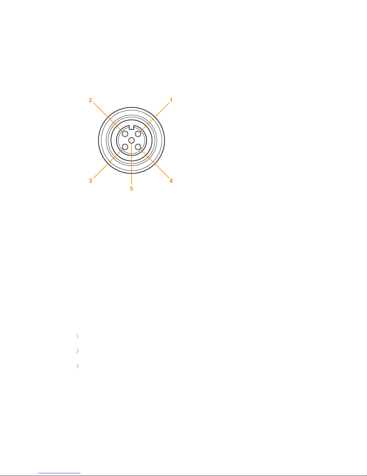
Confidea D-MIC microphones have a 5-pin connector to plug into the different Plixus compatible units.
Each pin has a distinct function:
Figure 1-33 Microphone connection
1. Pin 1: Microphone GND
2. Pin 2: Microphone signal
3. Pin 3: not used
4. Pin 4: LED +
5. Pin 5: LED -
Microphone Operation Modes
The microphone contains the following elements:
Indicator ring: shows the status of the microphone
Union nut: attaches the removable microphone to the unit
Microphone plug: connects the microphone to the unit
The color of the microphone indicator ring shows the status of the microphone:
IN STA L L MIC R O PH O N ES 65
Page 66

Color Status
Red (continuous) Microphone is active
Red (blinking)
Last minute of speech time (if set via software)
Speech Request (if set via software)
Green (continuous) Microphone is initialized
Green (blinking) Microphone request
IN STA L L MIC R O PH O N ES 66
Page 67

INSTALL DELEGATE UNITS
Keep at least one meter between two consecutive units to prevent howling effects.
Connect Plixus Units
For all system cable connections use CAT 5e FTP cables with an RJ-45 shielded connector. Plixus units have
an automatic port sensing feature. This means that it doesn’t matter which port is used, the units
automatically detect whether it is an input or output.
Each unit has two conference ports, below you can find a list with all Plixus compatible units and the
location of their conference ports.
Unit type Conference port location
Confidea T Bottom side of unit
Confidea F Built-in part of unit, location may vary depending on the type of unit.
uniCOS Built-in part of unit
Interpreter Desk Back side of unit
Connect To Plixus Engine
After connecting the different Plixus units to each other, connect the branch of units to one of the
conference network ports of the Plixus AE-R, MME or a network extender.
The Plixus AE-R and MME have four conference network ports.
General rule: 80 units can be supported directly by the central unit. However this depends on
type on units , cable sections and length. To calculate the exact amount with the Plixus power
calculator tool.
The central unit can deliver 400 W for external loads (for the Plixus AE-R this is 200W, which
you can increase to 400W with an additional external power supply)
The cable length to the first unit should not exceed 100m.
The cable length between the units should not exceed 100m.
IN STA L L DELEG A TE U NITS 6 7
Page 68
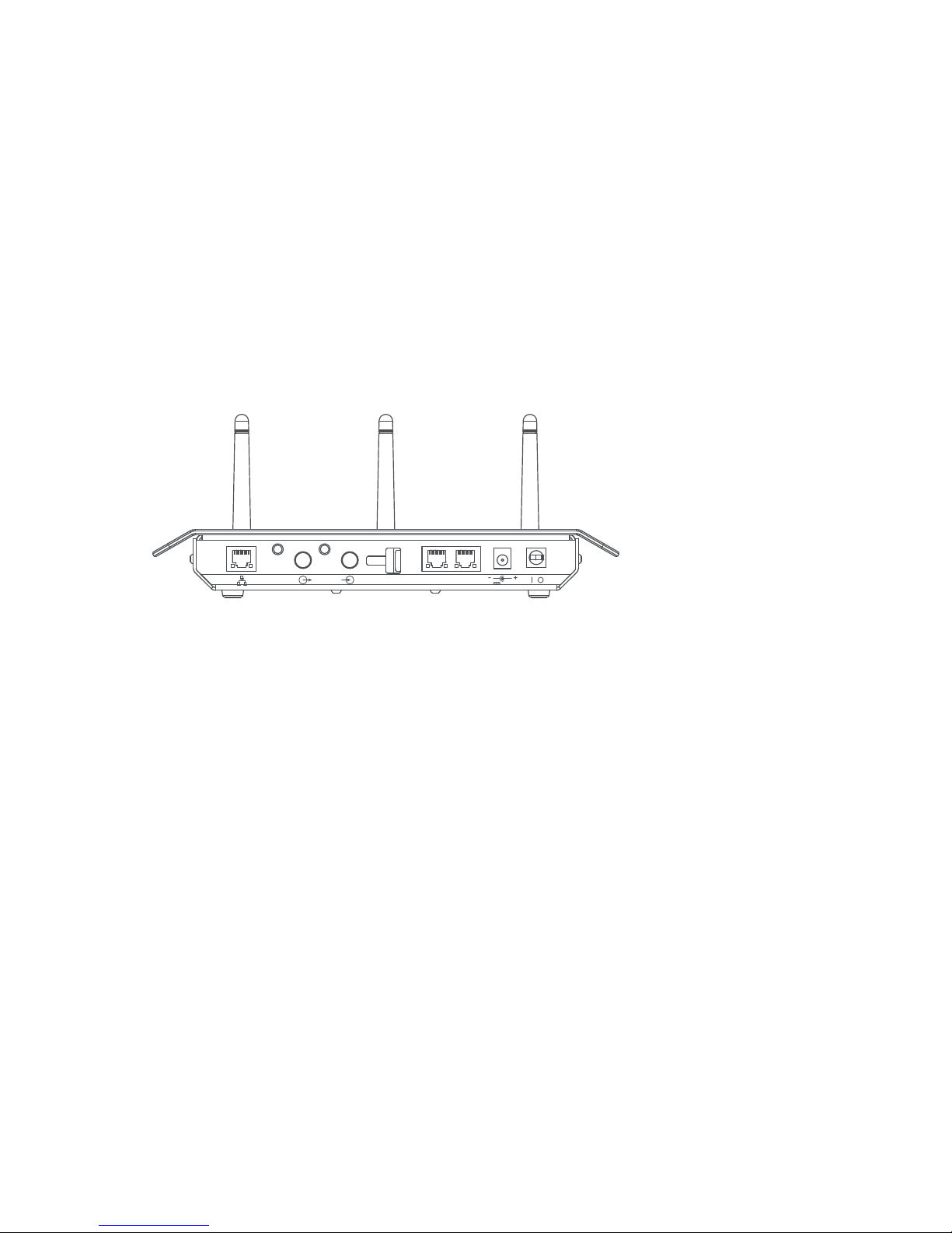
INSTALL CONFIDEA G3
Within Plixus it is possible to connect the engine to a Confidea G3 wireless system. When connected, Plixus
will treat the units the same way as all other wired units.
Connect Wireless Conference Access Point (WCAP) To
Plixus Network
Use the conference ports on the WCAP to connect to the Plixus engine or a network extender. In some
cases you want to have multiple WCAPs available ( see "Combine Plixus with Confidea G3" on page54 for
more information). You can daisy chain multiple WCAPs in one branch. We suggest not to put more than
eight WCAPs on one branch.
24V
AUX.
BALANCED
PORT 1 PORT 2
0.625A
Figure 1-34 Back view with conference ports on Confidea G3 WCAP
To supply power to the WCAP you can use its external power supply, but you can also use the power
supplied by the engine or network extender with power over Ethernet.
IN STA L L CO NF ID EA G 3 6 8
Page 69

CONFIGURATION
This chapter describes how to configure the Plixus network using the Plixus Core
web server. It includes a description of how to connect to the built-in web server
together with how to initialize units and configure audio settings to guarantee a
successful meeting.
Page 70

INTRODUCTION
Plixus features three different software components:
Default web server: the web server you see when you first use the system. Contains basic
functionalities that are also covered by Plixus Core.
Plixus Core: is a bundle of conference logic that runs on the Plixus system and allows to run the
conference system without a dedicated computer, but with the use of a web server.
CoCon: is the complete software suite for conference management.
Plixus Core
From CRP 5.1 onwards, the Plixus system provides the possibility to use Plixus Core. Below you can find a list
containing all functionality that is available in Plixus Core. This guide will discuss all these features together
with how to configure and use them.
Initialization of the units, creation of booths
Discussion parameters for microphone modes
Configuration of different audio settings such as the dynamics processor, auto gain reduction,
auxiliary input and output levels
Selection of basic audio routing presets (normal audio routing, N-1, external equalizer)
Interpretation configuration up to 11 languages and possibility to send language channels to
Dante
Operator page to control microphones
Recording of one or more channels
Regional settings such as date and time format
Manage network settings
Camera protocols
API
Plixus Core Versus CoCon
There are some differences between Plixus Core and the CoCon software. You cannot configure all
parameters of each feature in Plixus Core, for this you need a CoCon license. For a detailed description of
IN TRO DUCT IO N 70
Page 71

the difference between the two, see the table below.
Plixus Core CoCon 5.2
Start/Stop initialization Yes Yes
Retrieve initialization Yes Yes
Creation of synoptics No Yes
Support for multiple synoptics No Yes
Configuration of interpreter booths Yes Yes
Changing seat priority (delegate –
chairman)
Yes Yes
Default microphone mode No default, the last configured
mode is used
Yes
Meeting management No Yes
Delegate management (delegate
names, groups)
No Yes
Agenda creation No Yes
Voting management No Yes
Speech timers No Yes
Services (uniCOS) No Yes
Messaging (uniCOS) No Yes
Badges and authentication No Yes
Operator control Yes, limited through web server
Operator page
Yes, full Operator control
available
Activation of microphones Yes Yes
All microphone modes supported Yes Yes
Meeting statistics No Yes
Import/export of meeting data No Yes
Voting control No Yes
Signage No Yes
IN TRO DUCT IO N 71
Page 72

Plixus Core CoCon 5.2
Basic interpretation Yes, up to 11 language
configurable from web server in
Standalone
Yes
Advanced interpretation (with all ISO
90107 features)
No Yes
Three basic audio configuration
(normal, distance conferencing,
external equalizer)
Yes, configurable from web
server
Yes, included in Plixus Core
web server
Advanced audio configuration No, but once created with
CoCon, selectable from web
server
Yes, full audio routing matrix
available with Audio
application
Camera protocol Yes, sent from Plixus engine Yes, sent from Room Server
IN TRO DUCT IO N 72
Page 73
CONFIGURE IP SETTINGS
Before you start using the Plixus web server you need to configure your local IP settings to be able to access
the web server. Follow the procedure below to configure this.
To be able to access the web server your computer needs an IP address and subnet mask that can access
the IP address of the engine. The default IP address of the engine is 192.168.0.100, which means the
computer should have an IP address that is within the same subnet, like 192.168.0.200. The subnet mask
must be the same for all equipment on the network, being 255.255.255.0.
Change IP Settings In Windows
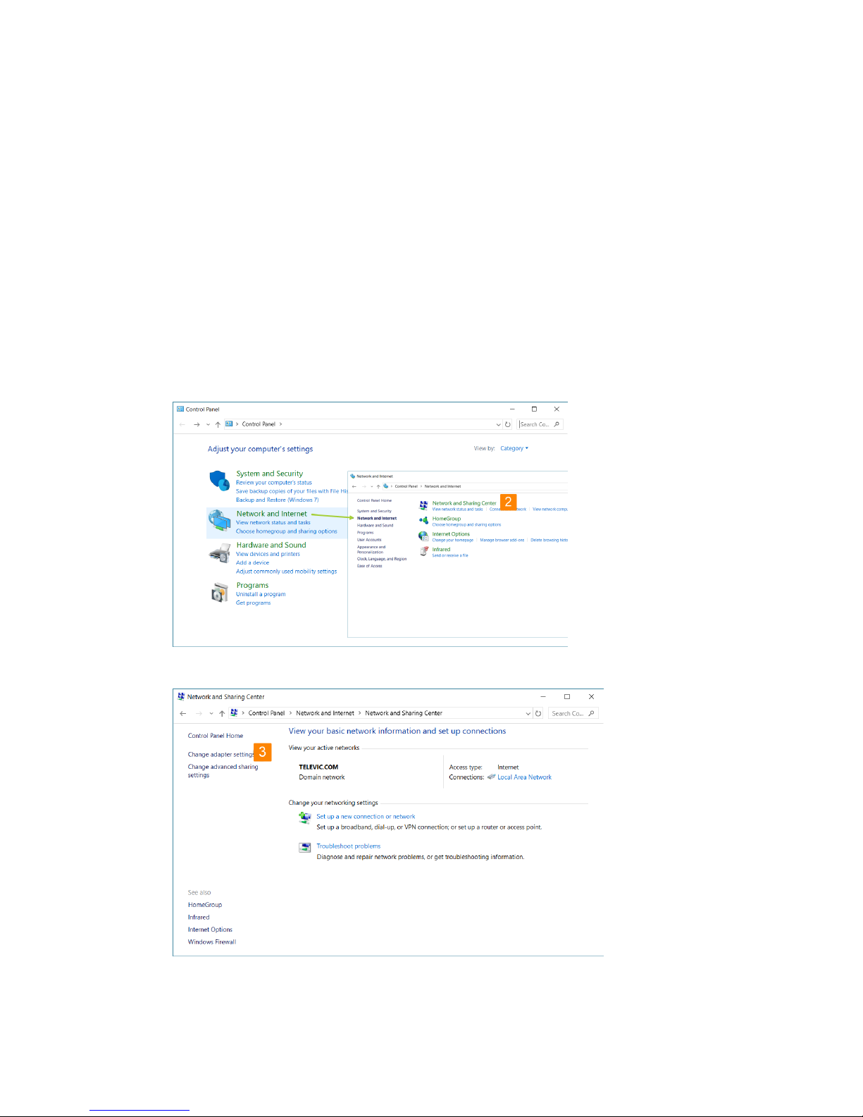
1. Go to Control panel.
2. Click Network and Internet and then Network and sharing center.
3. Click Change adapter settings in the menu on the left.
CO NF IG URE IP S ET TING S 73
Page 74
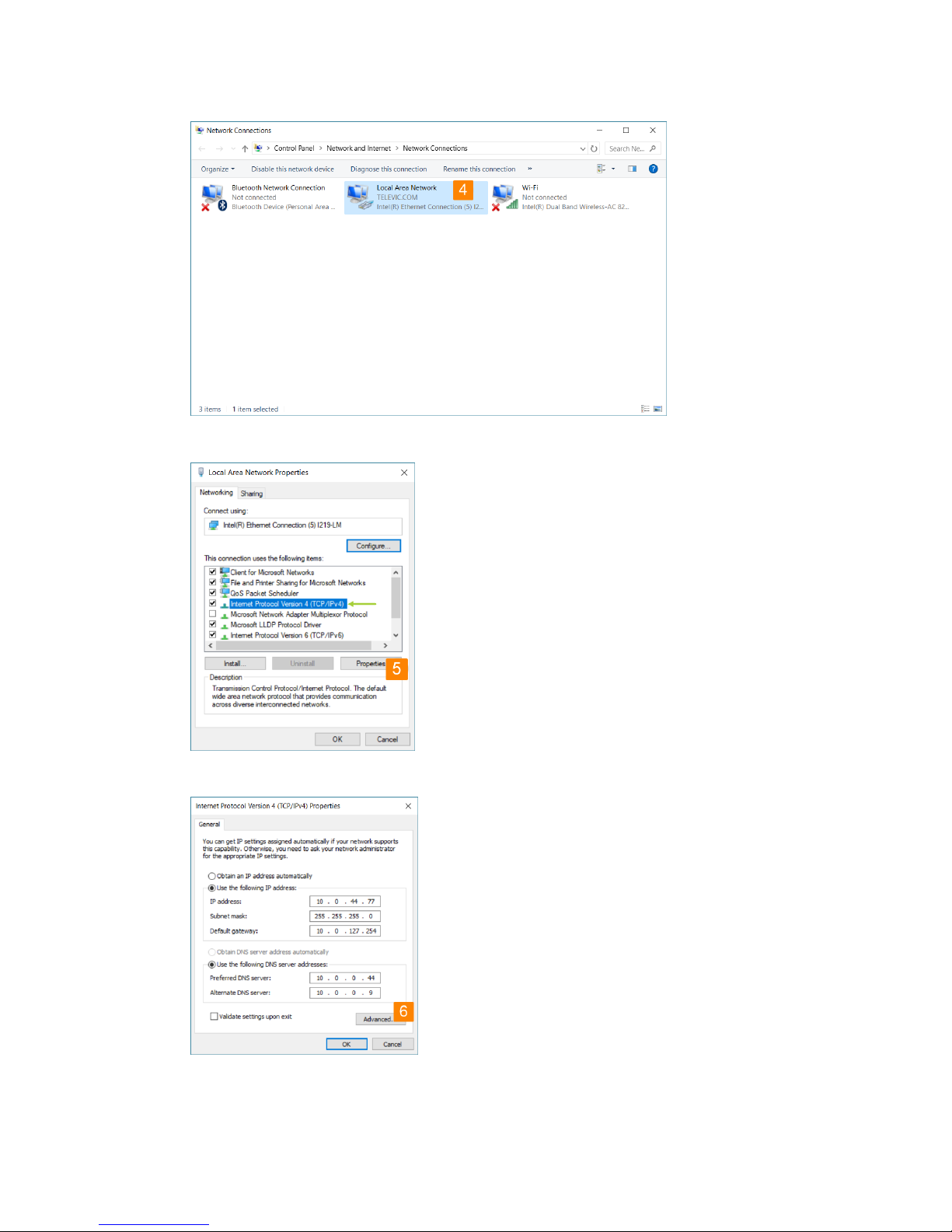
4. Right-click the Local Area Connection and select Properties.
5. Select Internet Protocol Version 4 (TCP/IPv4) and click Properties.
6. To assign a fixed IP address to your computer, click Advanced.
CO NF IG URE IP S ET TING S 74
Page 75
7. Click Add in the IP address pane.
8. Enter an IP address in the range of the engine, for example 192.168.0.26. Fill in 255.255.255.0
as subnet mask.
9. Click OK. You are now ready to access the WCAP.
Change IP Settings In MacOS
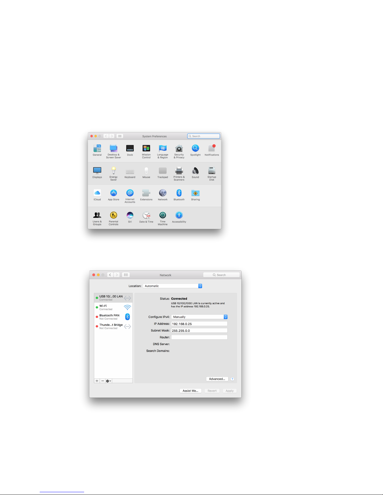
1. Go to the Apple Menu and select System Preferences.
2. Select Network from the menu.
CO NF IG URE IP S ET TING S 75
Page 76
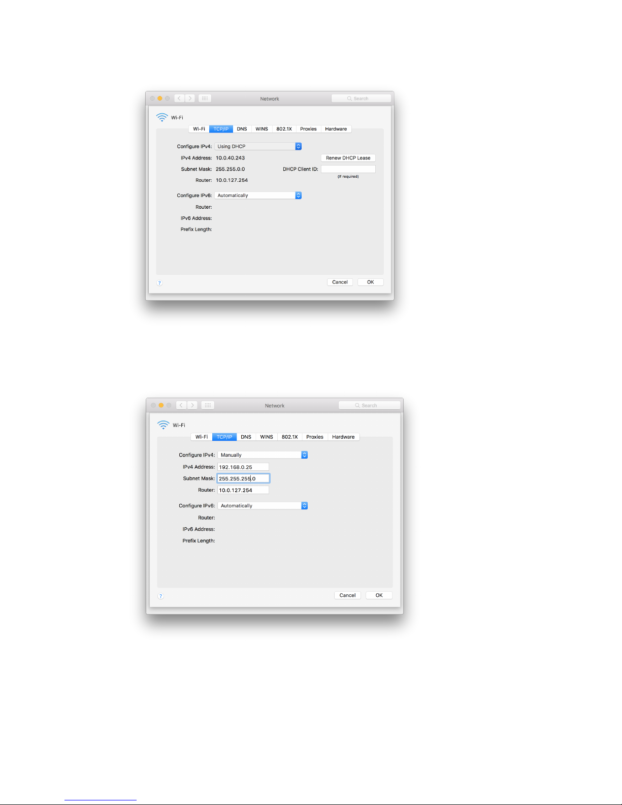
3. Click the Advanced button.
4. Select TCP/IP in the menu on top.
5. Change Configure IPv4 to Manually.
CO NF IG URE IP S ET TING S 76
Page 77

6. Enter an IP address in the range of the engine, for example 192.168.0.25. Fill in 255.255.255.0
as subnet mask.
7. Click OK.
CO NF IG URE IP S ET TING S 77
Page 78
GETTING STARTED WITH PLIXUS
CORE
Activate Plixus Core
To access the web server of the Plixus system, enter the IP address of the Plixus engine in your browser. The
default IP address of the Plixus engine is 192.168.0.100 with subnet mask 255.255.255.0.
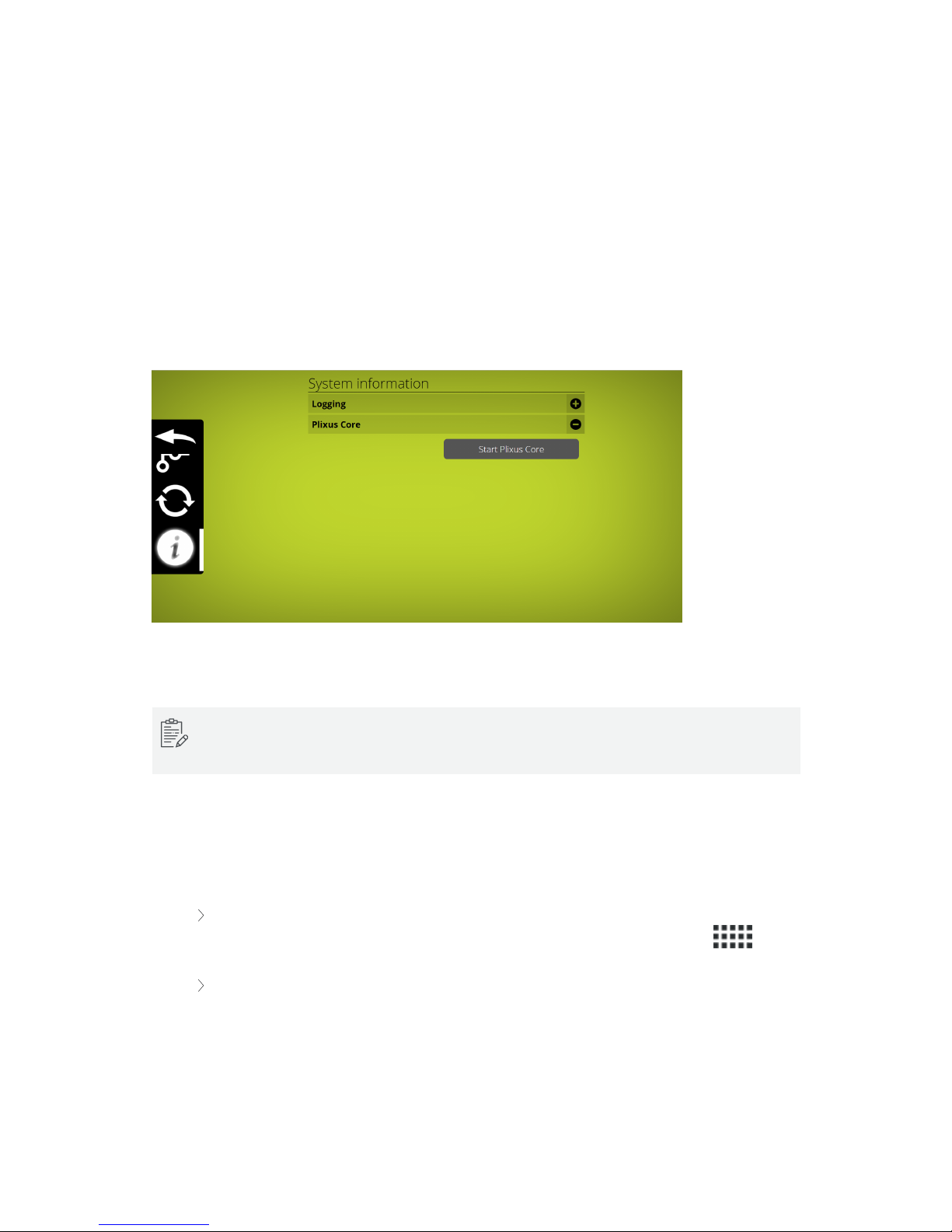
The first time you will need to activate Plixus Core. Go to Settings, select Info and click Start Plixus
Core.
Figure 1-35 Start Plixus Core from the default web server
If the web server does not refresh automatically, you can refresh it manually. Loading the new web
server may take up to 1 minute, the very first time.
Explore Plixus Core
The layout of the web server was designed to be intuitive and easy to use. All pages have a similar layout
which eases configuration. The general layout consists out of two parts:
The header element (1): this part contains the name ofthe product together with the title of
the page. From here you can also access the main menu by clicking the menu icon .
The body element (2): on this part of the page you can view and configure all settings. The
content will change depending on the menu item you select.
GET TI NG S TAR TED WITH P L IX US C O R E 78
Page 79
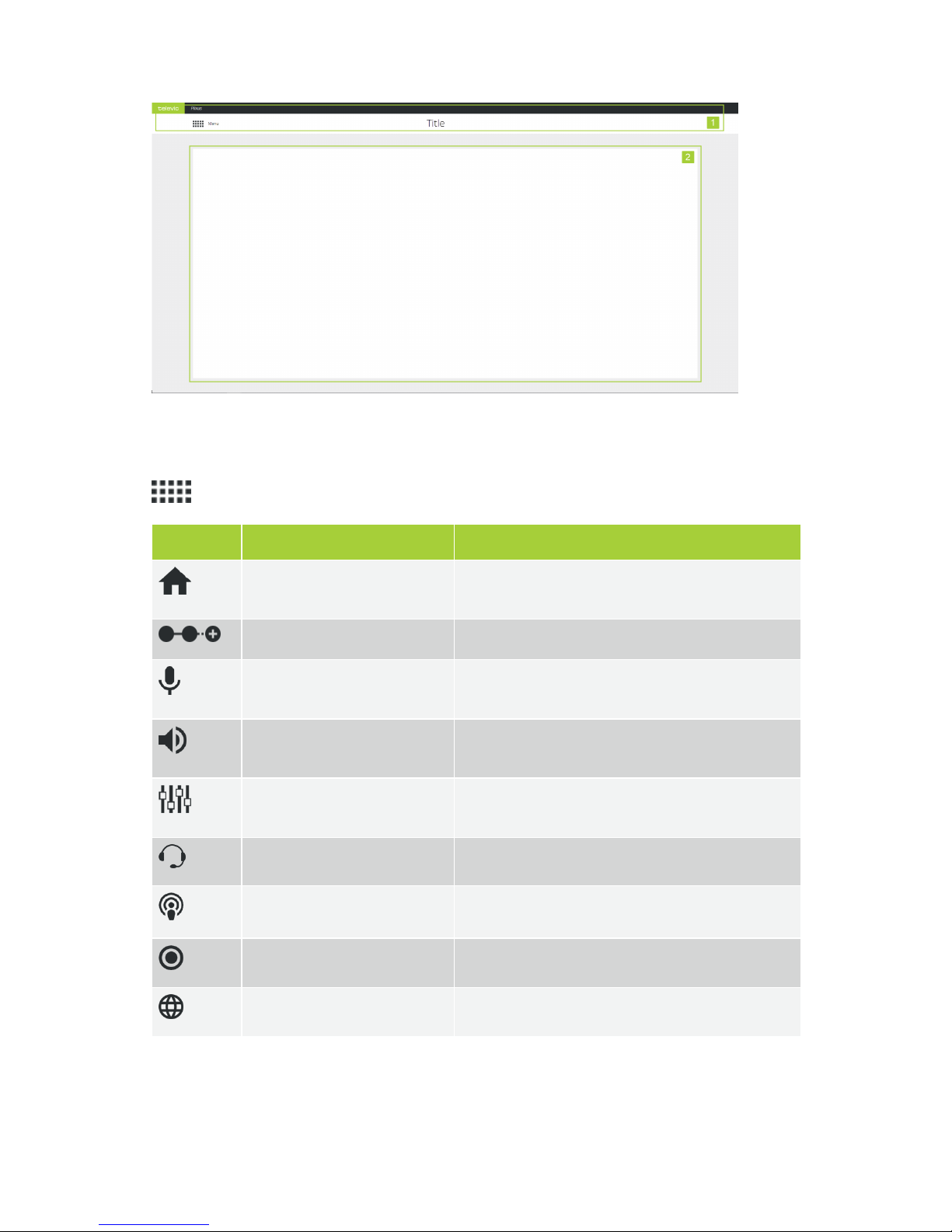
Figure 1-36 General layout of the web server
When you want to configure a certain setting, you simply select the correct sub menu from the main menu (
). The following sub menus are available:
Icon Sub menu Description
Home Return to the home screen where you see the most
important features and their configuration.
Initialization Define and configure units present in the Plixus network.
Discussion options Configure discussion options such as microphone to
define how to activate a microphone.
Audio Configuration of different audio options such as dynamic
processing and auto gain reduction.
Audio routing Configure the audio routing and the auxiliary input and
output levels.
Interpretation Configuration of the interpretation channels.
Operator Control all microphones in a meeting.
Recording Options to record the meeting.
Regional settings Change regional settings.
GET TI NG S TAR TED WITH P L IX US C O R E 79
Page 80
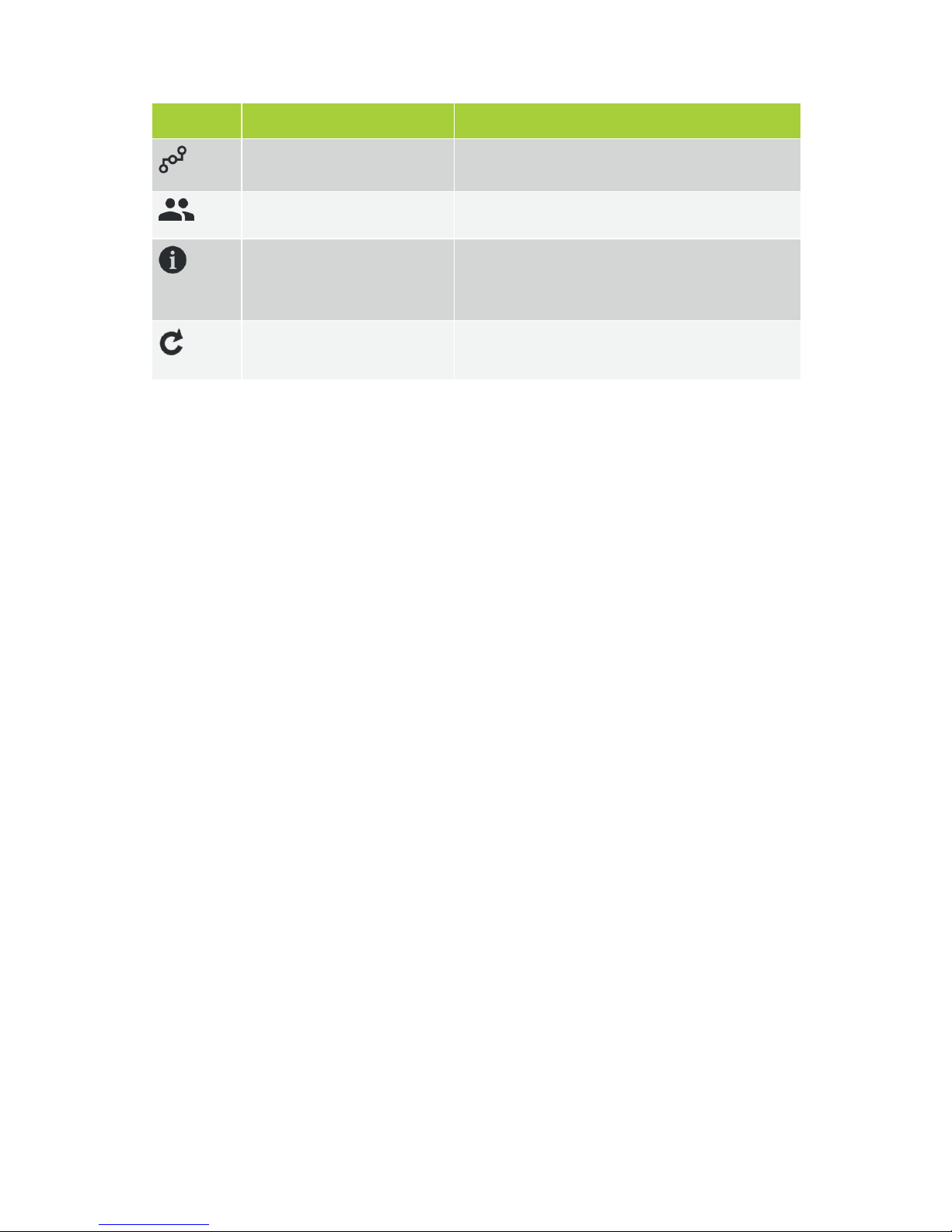
Icon Sub menu Description
Network Configure network settings and set camera protocol.
Users Change user name and password.
System info Contains system information such as license information,
system logging, (de)activation of Plixus Core and
configuration management.
Update versions Overview of all firmware and software version together
with the option to update to another version.
GET TI NG S TAR TED WITH P L IX US C O R E 80
Page 81

THE HOME PAGE
This is the default landing page of the web server and it shows general together with crucial information
about the current state of your conference system. Click the feature name to go to the dedicated page to
configure the setting.
On the left side you can see the following information:
General volume
Microphone mode
Number of active units
Number of faulty units
Number of connected but uninitialized units
Faulty units, means that there are units missing, that are normally in the initialization list. If this is
the case, this is indicated in red. A reason could be that they are not booted correctly or that they
are physically disconnected from the Plixus network.
On the right side you see the following items:
IP address o the system
MAC address of the Plixus engine
Connection status with CoCon Room Server
Connection Status with Plixus Core
By default it is not possible to disconnect from Plixus Core, however when Plixus Core crashes
home page will show Plixus Core Not connected. Click Restart to restart Plixus Core.
TH E H O ME PAGE 81
Page 82
INITIALIZATION
Introduction
The Plixus system always works with seats. A seat is a conceptual name for a unit or a group of units which
are combined on that seat. By default this is a one-to-one mapping, so every unit has one seat. However,
there can be more advanced cases where units are manually combined on a seat. During initialization you
can assigns units to seats.
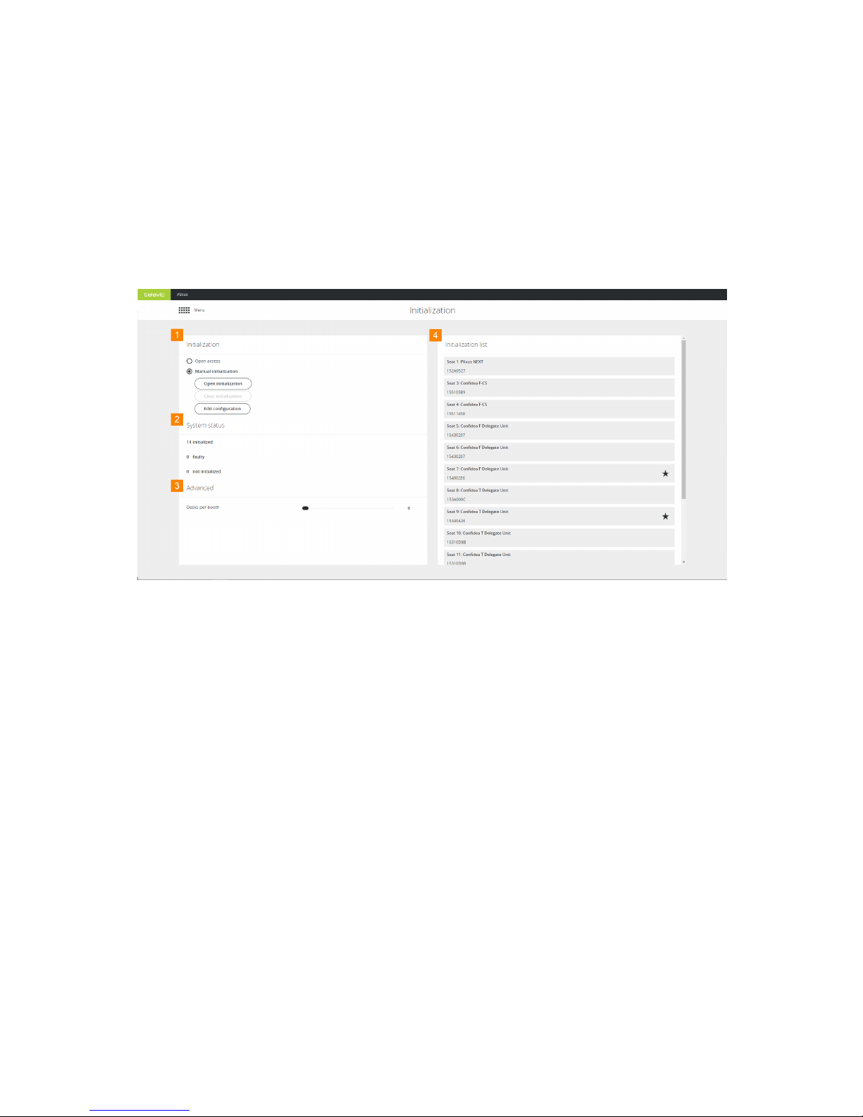
Figure 1-37 Initialization page
1. In Initialization on the left side of the page you select the mode of initialization.
2. System status shows the status of all units, you can see the amount of initialized, faulty and
not initialized units. Faulty units are units that were initialized, but are now missing. Not initialized
units are connected, but not yet initialized.
3. In the Advanced settings you can define the maximum number of desk per booth (for
interpretation).
4. The Initialization list on the right side shows all unitialized units, per unit you can see the
following information:
a. Seat number: position of the unit in the meeting room
b. Unit type
c. Chairman capabilities: can unit acts as chairman, indicated by star icon.
IN ITIAL I ZA TIO N 82
Page 83

d. Serial number: of the unit
e. Booths: all available booths together with the amount of desk per booth and the units.
How To Initialize Units
There are two initialization modes possible: Open access and Manual initialization.
OPEN ACCESS
This is the default mode. The main purpose of this mode is to provide a quick way to set up
and/or test the system.
Seats are automatically assigned to the units after startup. Assigning seats is done according to
the cabling topology of the units. This means that seat one is assigned to the first unit at port
one of the Plixus engine.
For network extenders connected to the Plixus port, seats will also start with port one of the
network extender. The system automatically discovers the redundant loops.
Interpreter desks are automatically divided into booths according to the setting Number of
desk per booth, under Advanced settings.
Upon restart of the Plixus engine (or Plixus Core) in Open Access, the network will be
rescanned and seats and desks will be assigned accordingly.
In Open Access mode, it is not possible to edit the configuration of the units (seat number or
delegate/chairman priority), nor change the configuration of the booths.
When changing from Open access to Manual Initialization, the initialization and seat order
is preserved.
MANUAL INITIALIZATION
Use Manual initialization when you want to define which unit is assigned to which seat
number. This can be important when using camera tracking as well as CoCon seat allocation.
Manual initialization allows you to edit the configuration in terms of chairman / delegate priority
and booth configuration after initial configuration.
Click Open initialization to start the initialization phase. This causes uninitialized
microphones to blink red and initialized microphones to blink green. Add units to the
initialization list by pressing the microphone button. During manual initialization you can
perform the following actions on the units:
IN ITIAL I ZA TIO N 83
Page 84
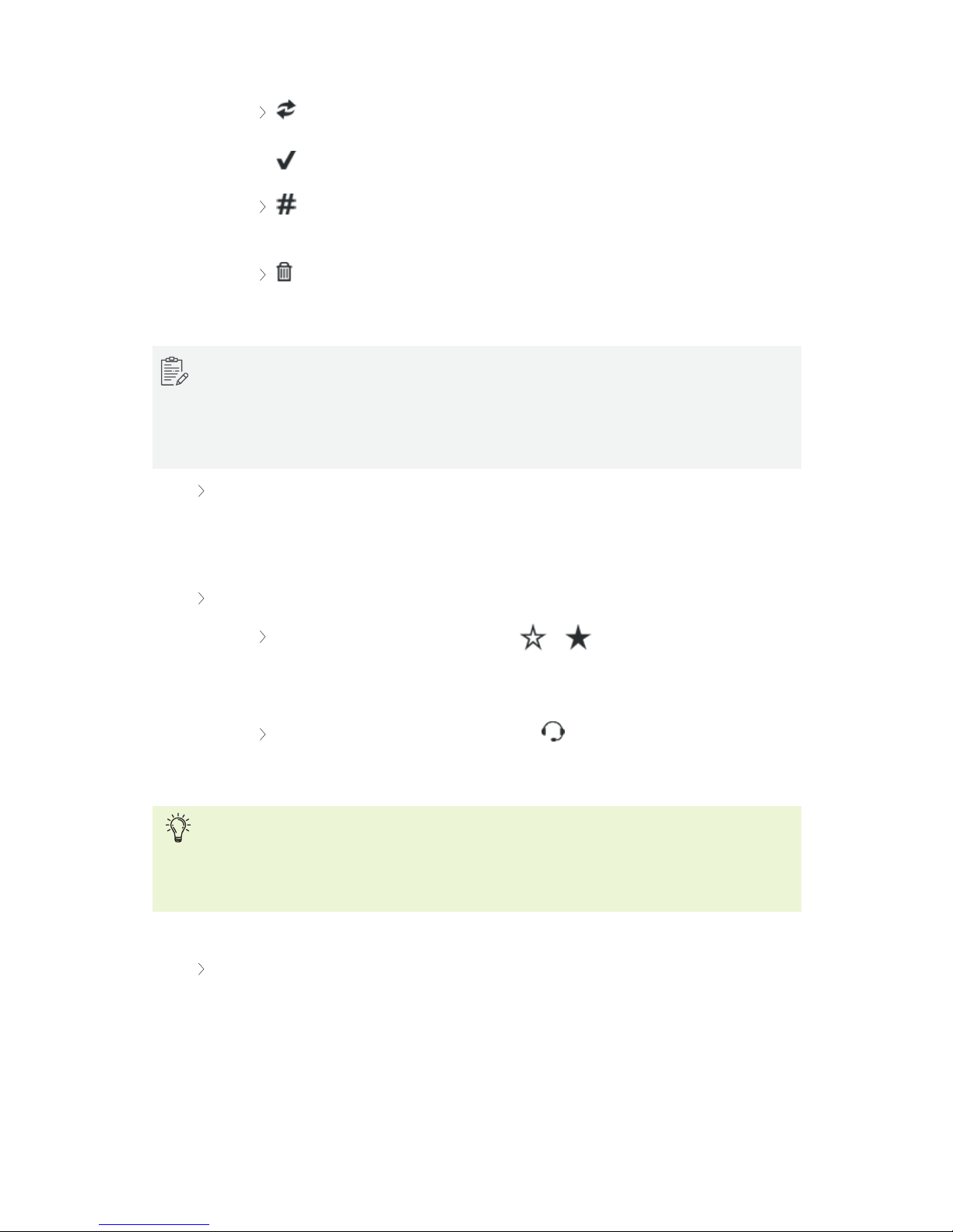
: click to swap unit. When a unit is faulty, it will be greyed out in the web server.
Click the icon and enter the serial number of the new unit. Click the checkmark icon
to confirm. Note that you can only replace units with units of the same type.
: click to modify the unit number. If you do this during the initialization, the next
assigned unit number will be the highest unit number + 1.
: click to remove individual units during initialization. After removal the
microphone LED will blink red again.
It might take several seconds before the microphones start to blink when you click Open
initialization.
You can only manual initialize units with a microphone button. Units without this button (e.g.
Confidea channel selector) are automatically assigned to a seat.
Click Stop initialization to finish and the seats are automatically assigned to the units.
Stopping initialization might take a while, up to one moment depending on the number of
units. The seat number will automatically map to the unit number and the Lingua ID’s to desks
in booths according to the setting Desk per booth.
Click Edit configuration to change the following settings
Chairman priority: click the start icon ( or ) to change priority of the unit. A
unit that is hardware-wise not a chairman unit can receive chairman properties. This
then becomes a VIP unit.
Booth configuration: click the booth icon to change the booth configuration.
Create new booths or group desks by changing booth and desk number.
Do not reload the page when editing the configuration.
Do not change properties during meetings, because this can disturb your meeting.
You can also use CoCon to configure different settings such as the priority of the unit.
Click Clear initialization to clear the initialization list, as consequence all units will start to
blink red. It is only possible to clear initialization when the initialization is open and units are not
faulty. Confirm to finish clearing the initialization.
IN ITIAL I ZA TIO N 84
Page 85
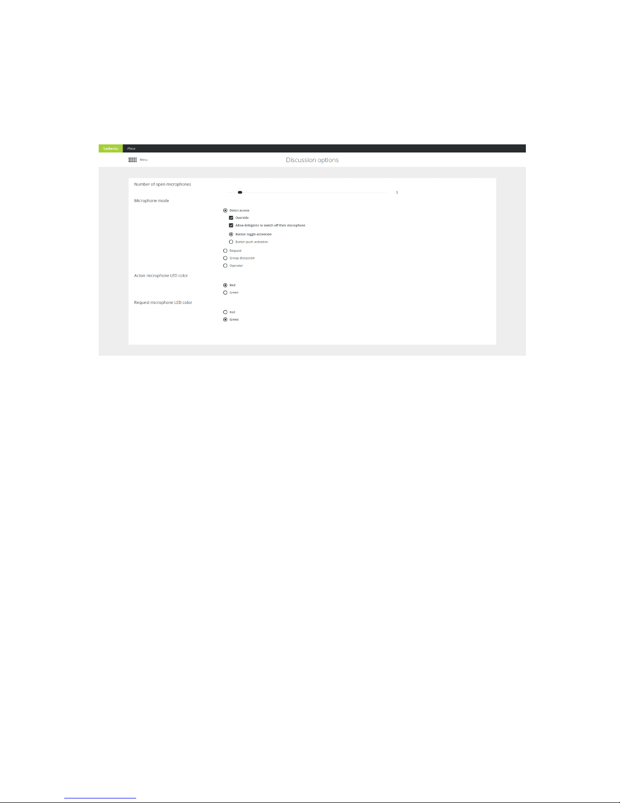
DISCUSSION OPTIONS
In this chapter you will find all information to configure the most important settings of your meeting. These
settings are the number of open microphones, the microphone mode and the color of the microphone LED.
Number Of Open Microphones
You can set the number of open microphones be between 1 and 25. This does not include the chairman
microphones. You can activate up to eight additional chairman microphones on top of the 25 delegate
microphones.
Microphone Mode
Different microphone modes are available and depending on the mode, you can configure additional
settings.
DIRECT ACCESS
With direct access delegates can activate their own microphone by pushing the microphone button. The
following additional settings are available:
DI SCU SSION O PTIO NS 85
Page 86

Parameter Description
Override
> Not-selected: microphone will not become active when the maximum
number of open microphones is reached and you press the microphone
button. Another active microphone must switch off first. Deactivation is
possible by the delegate, via the operator page, through the chairman using
the API or CoCon.
> Selected: when the maximum number of open microphones is reached, the
first activated microphone will switch off when a delegate presses its
microphone button.
Allow delegates to switch
off their microphone
With this option you ensure delegates cannot switch off their own
microphone. Only the operator or chairman can do this.
Button toggle activation
Press the microphone button once to activate the microphone.
Button request activation
Keep button pressed to activate to microphone. When you release the button,
the microphone will switch off.
REQUEST
In request mode you do not automatically get the floor when you activate your microphone. First you have
to request the floor. The chairman then assigns the floor to a speaker using the next-in-line button (or using
the operator page, CoCon or the API). Which delegate may speak first is defined by the first-in-first-out
principle. The chairman units (or VIP units) can always speak immediately and do not have to request the
floor.
For request mode additional settings can be configured:
Parameter Description
Allow delegates to cancel
their request
Select this option to allow user to cancel their request to speak by pressing the
microphone button.
Allow delegates to switch
off their microphone
Select to allow user to switch off their microphone by pressing the microphone
button. If not selected the microphone will only switch off when another
events stops the microphone for example by using the operator page.
Enable reply
Select to enable the reply functionality. With this function you can reply to a
certain speaker which will put you in different request list that has priority over
the default request list. Define which button to use for the reply function
(Reply, Prior, Next).
DI SCU SSION O PTIO NS 86
Page 87

VOX
Voice activation (VoX) is a mode where the microphone button is not used. The microphone becomes
active when it detects sound above a certain threshold. You can configure Voice activation in the Group
discussion mode. The following settings can be configured:
Parameter Description
Threshold The system will monitor the ambient sound level and will activate the microphone when it is
above the configured threshold value.
Hold time Determines the number of seconds the microphone stays active after detection of the last sound
above threshold.
GROUP MODE
Group mode is a semi-automatic mode for standalone conferences where less protocol has to be followed
and no operator is available. Pressing the microphone button activates the microphone unless the
maximum amount of open microphones is reached. In this case the microphone will go into request mode.
When another microphone becomes inactive, the first unit in the request list will become active.
This mode has 3 activation types: toggle, push to talk and vox.
Mode Description
Toggle Press microphone button once to activate microphone.
Push to talk Keep microphone button pressed to activate microphone.
Voice
activation
Microphone becomes active when it detects sound above a defined threshold. For more
information see "VoX" .
OPERATOR
With the operator mode delegates cannot activate their own microphone. Only a command from CoCon,
the operator page or the API can activate these delegate microphones. Delegates can deactivate their
microphone by pressing the microphone button. Chairman can always activate microphones and use the
priority button if he wants to switch off the delegate microphones.
Microphone LED
Change the LED color of an active microphone ora microphone in request. By default the LEDof an active
microphone is red and for a microphone in request green.
DI SCU SSION O PTIO NS 87
Page 88
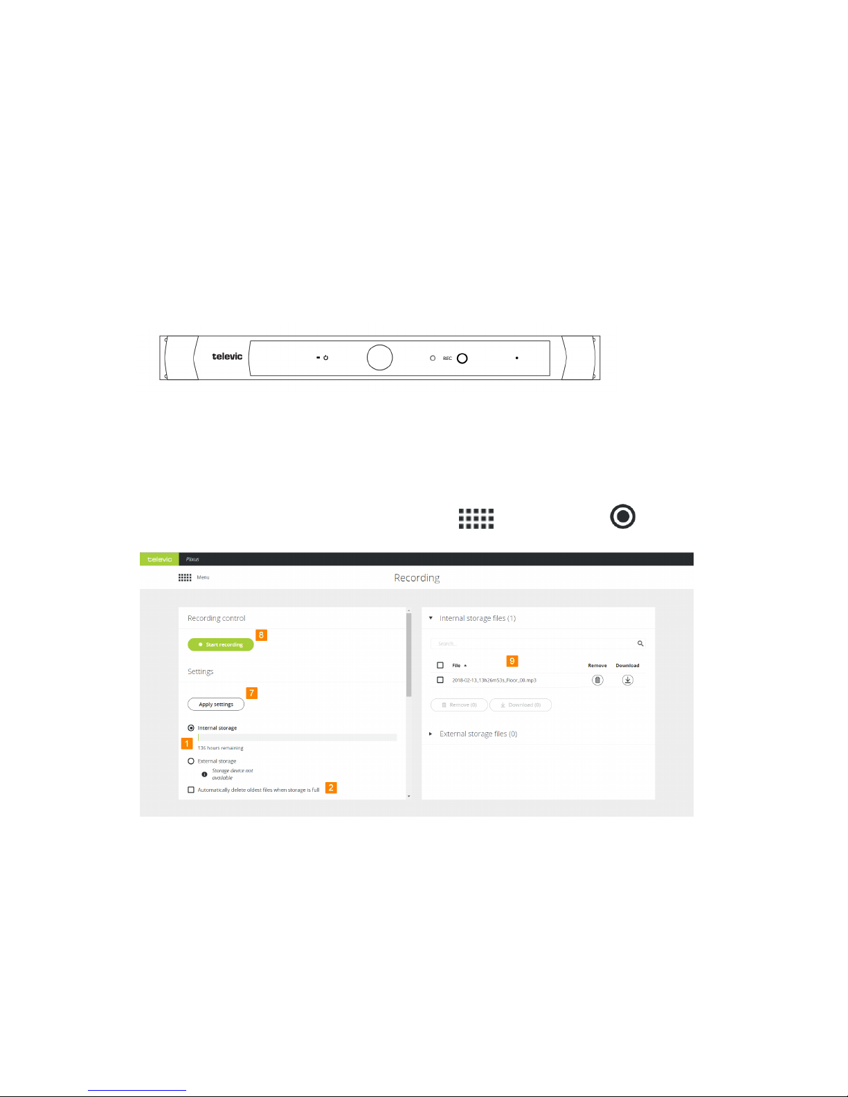
RECORDING
With the Plixus AE-R you have the option to record meetings. You can start recording by pressing the button
on the engine or by using Plixus Core. Save the recording on the integrated hard drive or to an external USB
device.
Record Using The Record Button
Press the record button on the front display of the engine to start recording. A LED light next to the button
indicates that the engine is recording. Press the button again to stop the recording.
Figure 1-38 Record button on Plixus AE-R engine
Record Using Plixus Core
To record your conference using Plixus go to the main menu and select Recording .
REC O R DIN G 88
Page 89
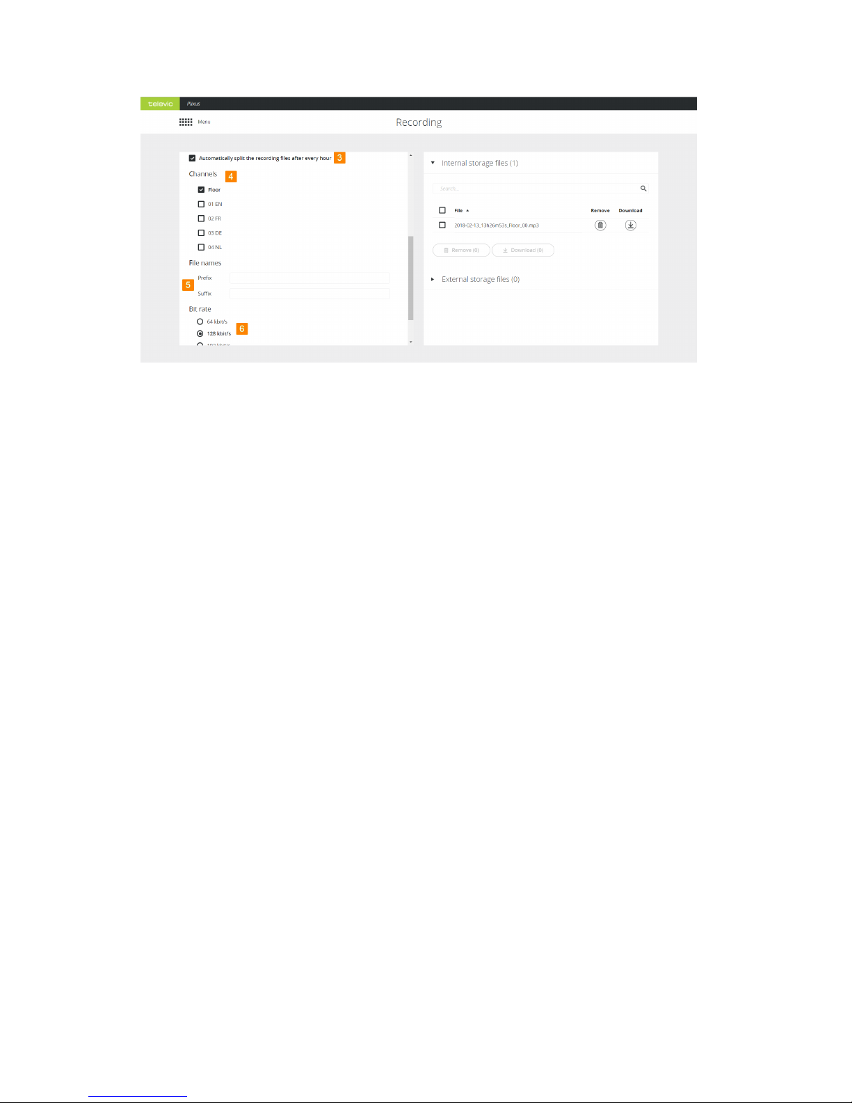
1. Select where to store the recording. Select Internal storage to store the recording on the engine
locally or select External storage to store the files to an external USB device connected to the
engine. For the internal storage you can see the remaining disk space, this depends on the audio
quality you selected.
2. Select this option to delete the oldest files on the engine or external USB device when there is no
more disk space.
3. This option splits up recordings into different files when the recording time is larger than one hour.
4. Select the channels you want to record. Per channel a different recording will be created.
5. Define a prefix and/or suffix to be automatically added to your recording file name. By default the
date and time are added to the file name.
6. Select the quality of the recording. By default 128kbit/s is selected which renders medium quality
audio files.
7. Click Apply settings to save the configuration.
8. Click Start recording to start and click Stop recording to finish your recording.
REC O R DIN G 89
Page 90
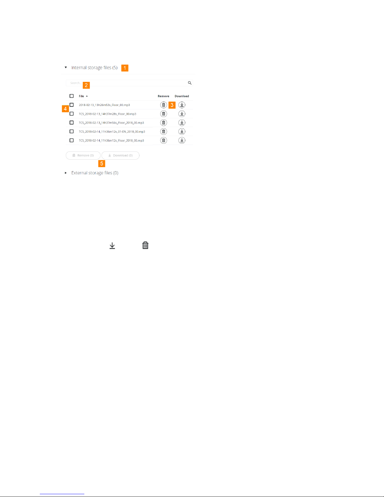
Manage Recorded Files
Figure 1-39 How do download and remove your recorded files
1. Go to the location where your files were recorded: on the engine itself or on an external USB
device.
2. You can search for specific files using the Search bar.
3. Download or remove single files using the buttons next to the file.
4. Select multiple files using the check boxes next to the file names.
5. Download or remove the selected file by clicking on the Download or Remove button.
REC O R DIN G 90
Page 91
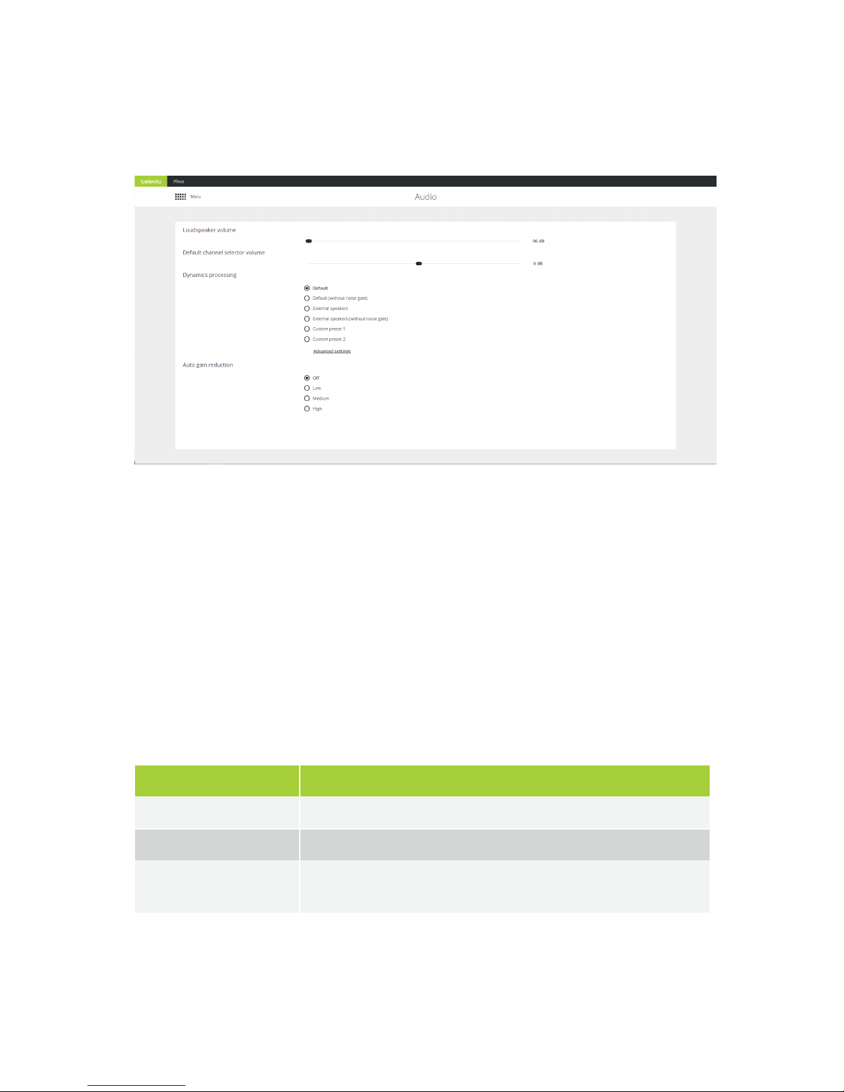
AUDIO SETTINGS
On the Audio page you can configure all general audio settings for the Plixus system.
General Volume
This sets the volume for the loudspeakers in the room. The value can range from -96dB to +6dB. You can
also change the volume by turning the control dial of the MME or volume dial of the AE-R.
Dynamics Processing
The dynamics processor settings are global settings that are applied to every microphone unit individually.
These settings determine the dynamic range of the audio input.
There are four default presets available for the user, for a detailed description of these presets see the table
below. Click Advanced settings to see these presets and edit them. However, you cannot overwrite
predefined options, you can only save changes as Custom preset 1 or 2.
Preset Description
Default This preset has been optimized for medium-size conference rooms.
Default (without noise gate) Removes the noise gate, use when the noise in the room is limited.
External speakers Shifts the knee-point of the compressor stage to a higher input value resulting
in less chance of feedback when external speakers are used.
AU D IO SE TTING S 91
Page 92
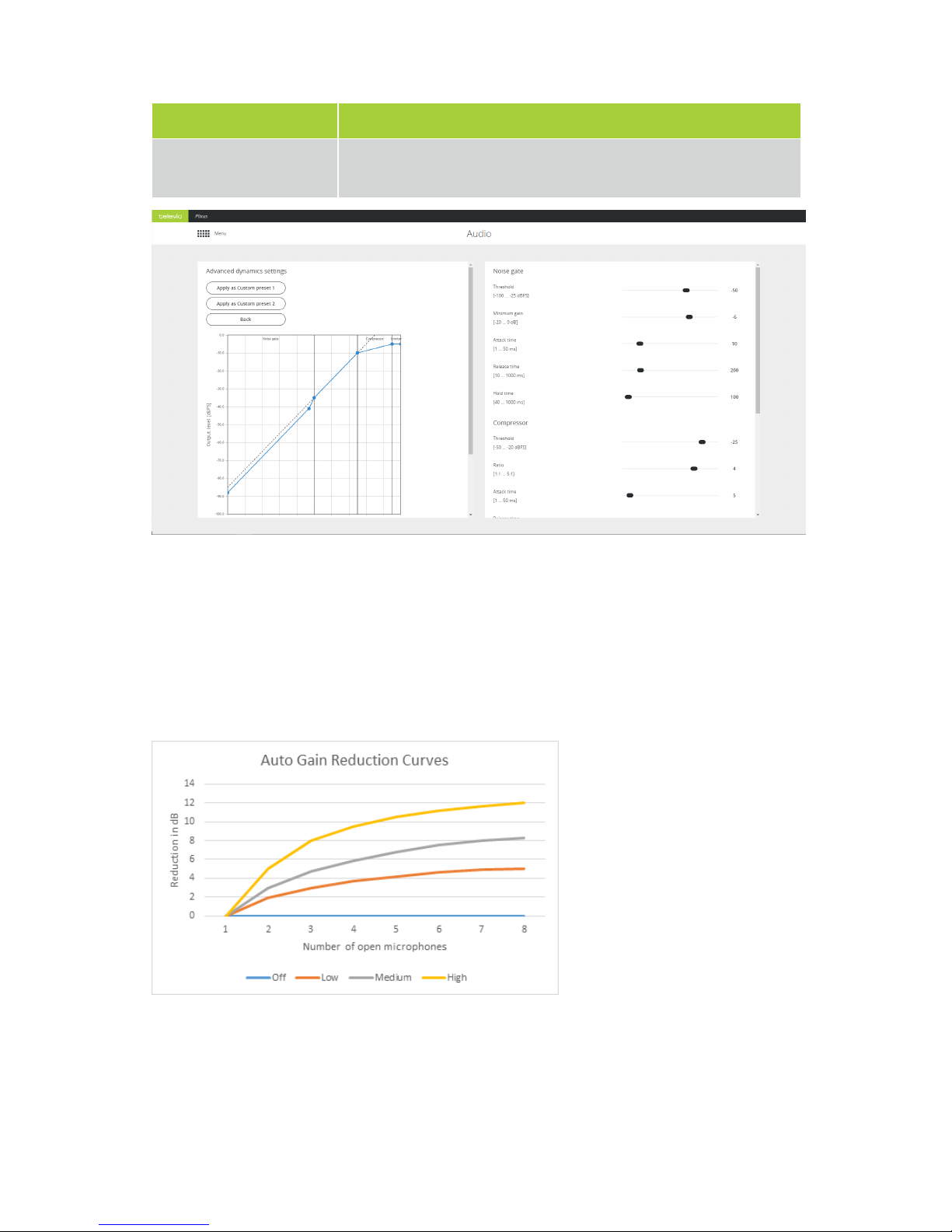
Preset Description
External speakers (without
noise gate)
Same settings as external speakers, but without the noise gate.
Figure 1-40 Figure 3 13 - Audio - Advanced dynamics settings
Auto Gain Reduction
Auto gain reduction reduces the amount of gain in signal in function of the amount of open microphones.
As the number of open microphones causes the noise to go up, a gain reduction can increase the
intelligibility. There are four presets available with different gain curves:
In rooms where the acoustics are very good, the auto gain reduction may be turned off. In smaller rooms or
rooms where external speakers are quite close to certain microphones, it can be challenging to have
enough intelligibility everywhere without feedback. Therefore a medium or high setting may be required.
AU D IO SE TTING S 92
Page 93
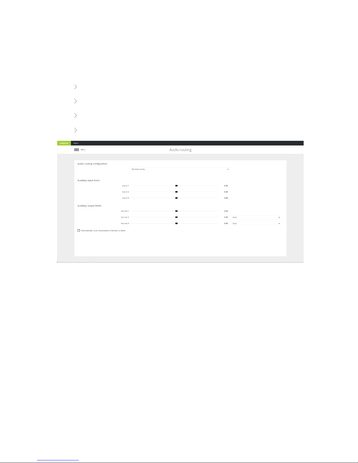
AUDIO ROUTING
With audio routing you can control all routing configurations and the auxiliary levels. You can configure the
following settings:
Audio routing configuration
Auxiliary input levels
Auxiliary output levels and selection of the output channel
Automatically route interpretation channels to Dante
Figure 1-41 Audio routing page
Audio Routing Configuration
By default there are three preconfigured basic routing options. They are explained here with the picture of
the CoCon routing matrix:
NORMAL ROUTING
No additional audio routing is done.
AU D IO RO UTING 9 3
Page 94
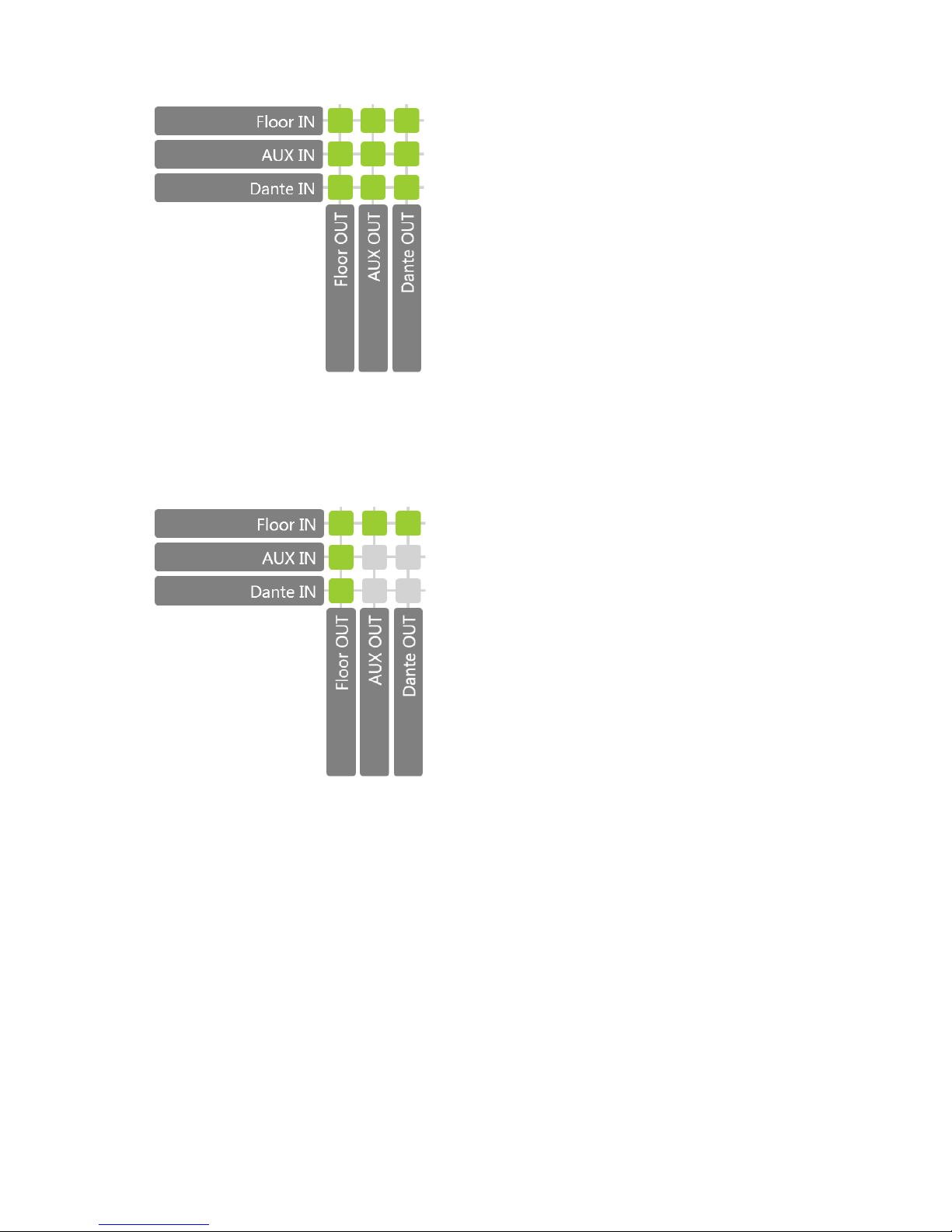
DISTANCE CONFERENCING
This adds an external signal, using AUX IN, to the local floor signal and sends the local floor signal, using
AUX OUT, to a remote party, for example sitting in a different room.
EXTERNAL EQUALIZER
This option allows you to add an external signal processing equipment or a mixing board.
AU D IO RO UTING 9 4
Page 95

PRESETS FROM COCON AUDIO APPLICATION
You can use the CoCon Audio application to create additional audio routing configurations. After creation
these are sent to and saved on the Plixus engine. These are then accessible from the web server, even
when CoCon is not running. In contrast to the predefined configurations you can still edit these
configurations.
Auxiliary Levels
Auxiliary input levels and output levels are by default referenced on 0dB. This means there is no
amplification or gain reduction. You can adjust the levels manually by using the scroll bar.
Additional Options
When a predefined audio configuration is selected and you use the web server for the interpreter
configuration, there two additional functions are available.
You can assign an outgoing language channel to Aux 2 and 3. In the drop-down box select the
desired outgoing channel. This is only possible when the languages are configured in the web
server.
All language channels that you configure in the web server can be automatically routed to
Dante when you select the checkbox Automatically route interpretation channels to
Dante.
This means the following for the Dante channels: The floor is always routed to channel
number1. From then on, with the option activated, the other x language channels follow on
channel 2 until x+1
AU D IO RO UTING 9 5
Page 96
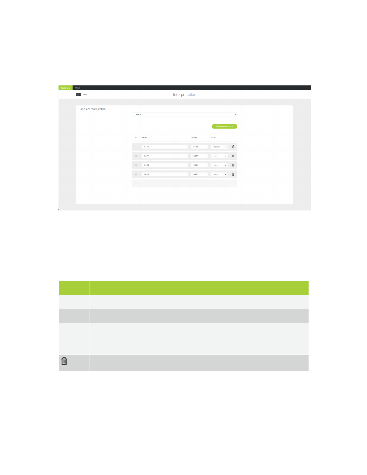
INTERPRETATION
On the Interpretation page you configure the languages needed for the meeting. You can add up to eleven
channels.
Figure 1-42 Interpretation page
Add New Language
To add a language configuration, click the bottom empty field in the table in the Column Name. You can
define the following parameters:
Parameter Description
Name Name the language, not used for display but is used for the API output.
Display Text to display on relays, channels and channel selectors. Limited to seven characters.
Booth Select one of the initialized booths from the drop down box. The value “------“ represents a
virtual booth. This means that you can use the language by selecting it on B/C channels on the
Lingua ID.
Remove the configured language.
Click Apply configuration to activate it.
IN TER PRE TAT IO N 96
Page 97

Add Interpretation Configuration From CoCon
Figure 1-43 How to add language configurations created in CoCon
You can also configure languages in the CoCon Interpretation application. You can find these
configurations in the drop down list on top of the page. Select the configuration and click Apply
configuration to use it. When you open a different configuration, the default configuration will be cleared.
IN TER PRE TAT IO N 97
Page 98
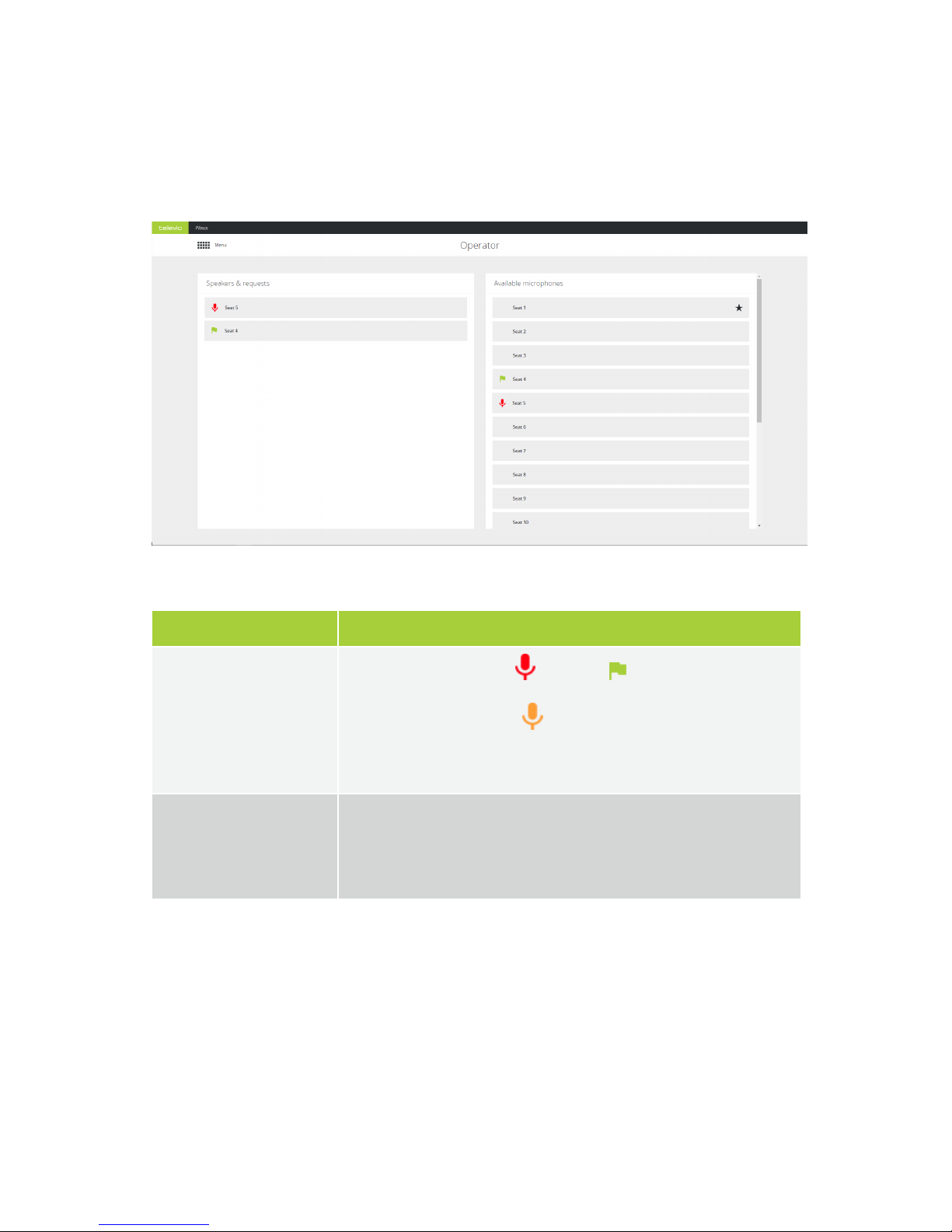
OPERATOR
On the Operator page you can control the microphones in the meeting and see how is speaking or
requesting to speak. The Operator page consists out of two parts:
Figure 1-44 The Operator page
List Description
Speakers & request
Shows all active microphones , all requests (only possible with Request
microphone mode) and replies (if configured). Click on an active
microphone to switch it off. Click on a microphone in request or reply to turn
it on.
Available microphones This list shows all microphones, sorted on seat number, with an indication of
the chairman priority and the active or request microphones. Clicking on a
microphone will change the status from either to active or switch off the
microphone.
OPE RATO R 98
Page 99
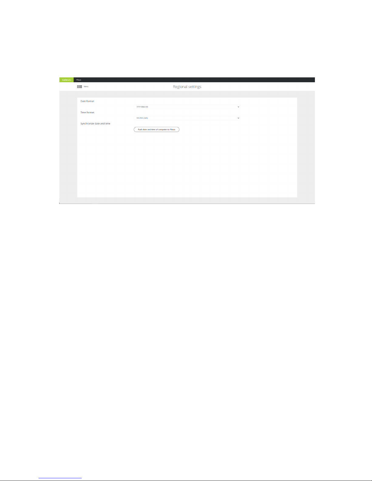
REGIONAL SETTINGS
Go to the Regional settings page to change the date and time format.
Figure 1-45 The Regional settings page
Click Push date and time of computer to Plixus to synchronize to time of your Plixus system with that
of your computer.
REG IO NAL SETT IN G S 9 9
Page 100
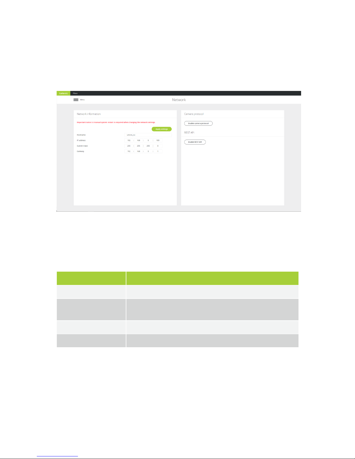
NETWORK SETTINGS
On this page you can adjust the network settings of the Plixus engine and configure the camera protocol
which to sent from the Plixus engine to the camera tracking system. Here you are also able to enable the
API.
Figure 1-46 Network settings page
Network Information
You can configure the following network parameters:
Parameter Description
Hostname Is the name of the Plixus engine.
IP address The IP address to access the engine, default value is
192.168.0.100
. When you
change the IP address, you need to restart the engine to complete the action.
Subnet mask Default subnet is 255.255.0.0
Gateway The access point to another network.
Camera Protocol
Camera protocol is disabled by default. When you enable the camera protocol you can configure the
following parameters:
NE TWO RK SET TIN G S 1 0 0
 Loading...