

Page 1

Electric-arc fusion splicer
EN
Ref. 232103
Art. Nr. OSSGN
Operating instructions
www.televes.com
Page 2

Page 3

ENGLISH
EN
Contents
1 General information ........................................................................... 5
2 Fusion splicer ................................................................................. 6
3 Keyboard ..................................................................................... 7
4 Commissioning and menu description ......................................................... 7
4.1 Start ..................................................................................... 7
4.2 Splicing mode ........................................................................... 7
4.3 Oven mode ............................................................................. 9
4.4 Settings ................................................................................. 10
4.4.1 Splicing settings ....................................................................... 10
4.4.2 Power settings .......................................................................... 12
4.4.3 Screen settings ........................................................................ 12
4.4.4 Access and communication settings ..................................................... 12
4.4.5 Language .............................................................................. 12
4.4.6 Schedule .............................................................................. 12
4.4.7 Factory settings ......................................................................... 12
4.5 Memory .................................................................................. 13
4.6 Maintenance ............................................................................. 13
4.6.1 Electrode stabilisation ................................................................. 13
4.6.2 Sensor value ............................................................................ 13
4.6.3 Dust test ............................................................................... 13
4.6.4 Arc calibration ......................................................................... 13
4.6.5 Engine ................................................................................. 14
4.6.6 Change electrodes ...................................................................... 15
4.6.7 Self-test ................................................................................. 15
4.6.8 Electrode limit .......................................................................... 15
4.6.9 Maintenance information ................................................................ 15
5. Splicing process ................................................................................ 16
5.1 Electrode and element inspection ....................................................... 16
5.2 Fibre preparation ....................................................................... 16
5.3 Fibre type ................................................................................. 16
5.4 Introducing the ber into the fusion splicer. ............................................... 17
5.5 Heat-shrink protection .................................................................... 17
6. Annexes ........................................................................................ 18
6.1 Annex A .................................................................................. 18
6.2 Annex B .................................................................................. 18
6.3 Annex C ................................................................................. 19
7 Maintenance .................................................................................... 19
7.1 V Groove. . . . . . . . . . . . . . . . . . . . . . . . . . . . . . . . . . . . . . . . . . . . . . . . . . . . . . . . . . . . . . . . . . . . . . . . . . . . . . . . . . 19
7.2 Fibre pushers ............................................................................. 19
7.3 Reecting mirrors ......................................................................... 19
7.4 Cameras or lenses ........................................................................ 20
7.5 Pusher substitution ....................................................................... 20
7.6
Changing the cleaver's cutting blade position ............................................ 20
7.7 Adjusting the cleaver's cutting blade height ............................................... 21
7.8 Replacing the cleaver's cutting blade ...................................................... 21
7.9 Stripper ................................................................................... 21
7.10 Battery ................................................................................... 22
8 Specications ................................................................................... 22
Fusion splicer
Ref. 232103
Page 4

4
General conditions for installation
1. Read this manual before operating or connecting the equipment.
2. Keep these operating instructions in a safe place.
3. Pay attention to all the warnings.
4. Follow all instructions.
5. Do not use this equipment near water.
6. Clean the outside with a dry cloth only.
7. Only use attachments/accessories specied by the manufacturer.
8. Do not step on or pinch the network cable of the power supply
unit; pay special attention to plugs, power connections, and the
spots where they leave the equipment.
9. Refer all servicing to qualied service personnel. Servicing is
required when the apparatus has been damaged in any way, such
as power-supply cord or plug is damaged, liquid has been spilled
or objects have fallen into the apparatus, the apparatus has been
exposed to rain or moisture, does not operate normally, or has
been dropped.
Warning
Equipment shall not be exposed to dripping or splashing and no
objects lled with liquids, such as glasses, shall be placed on the
equipment.
Ambient temperature should not be higher than 50 °C.
Do not place the equipment near heat sources or in a highly humid
environment.
Do not place the equipment in a place where it can suer vibrations
or shocks.
Please allow air circulation around the equipment.
Do not place naked ames, such as lighted candles on or near the
product.
How to charge the equipment safely
Power requirements for the power supply unit should be: 100-
240V~ 50/60Hz.
To disconnect the power supply from the mains pull the plug never
the cable.
I t is strongly recommended not to connect the power supply unit to
the mains until all connections have been done.
Reduce the risk of re or electric shock, do not expose this power
supply unit to rain or moisture.
Fusion splicer precautions
1 The charging voltage of this fusion splicer is limited.
Always use the power supply unit provided with the equipment
to charge the internal battery.
2 Should the fusion splicer show any of the following anomalies
at some point:
- Weird smoke, smell or noise.
- Extreme heat.
- Weird liquid or matter inside the equipment.
- Breakdown or damage caused by falling o crashing.
You must switch o the equipment and immediately remove
the battery. Then, contact the Technical Support department of
Televés to proceed with its inspection or repair.
3 Internal manipulation of the fusion splicer involves losing the
product warranty (do not take the equipment apart).
4 4 Any errors in the equipment's external maintenance could
damage the fusion splicer or result in injury to the operator (carefully follow the maintenance instructions).
5 Never use the fusion splicer in the presence of ammable gases
or liquids. Otherwise, it may lead to res, explosions or other
serious consequences.
6 This fusion splicer is only used for optical bre fusion, and
should not be used for any other purposes.
7 Do not expose the fusion splicer to high temperature or hu-
midity.
8 Avoid working in environments that are dusty or contain air-
borne particles. This situation may cause failure in the fusion
operations or damage to the equipment.
9 Using the fusion splicer under dierent climatic conditions
(going from a cold to a warm environment, for instance) may
generate condensation in the equipment. Wait for the condensation to completely disappear before working with it.
10 To keep the appropriate performance of the fusion splicer (ba-
sed on the use that is made of it) we recommend cleaning the
equipment periodically.
11 The fusion splicer is calibrated in-factory. Avoid strong vibra-
tions or impacts, and use its own case for transport and storage.
12 Due to the high complexity of this equipment, it should only
be repaired by Televés.
Notes
Be aware that ignoring these warnings or using the fusion splicer
inappropriately may result in serious injuries: please follow the
recommended safety standards for this equipment.
Always use safety goggles when working with optical bre.
Simbology
The power supply unit is designed for indoor use.
The power supply unit meets the safety requirements for
class II equipment.
The equipment cannot be treated as regular household waste,
and should be handed over to the appropriate collection
point for waste electrical and electronics equipment (WEEE).
The equipment includes a recyclable battery; prior
to handing it over at the WEEE collection premises, the
battery should be removed from the equipment and
separately delivered for appropriate management.
The equipment complies with the CE mark requirements.
Important safety instructions
Page 5
5
1. General Information
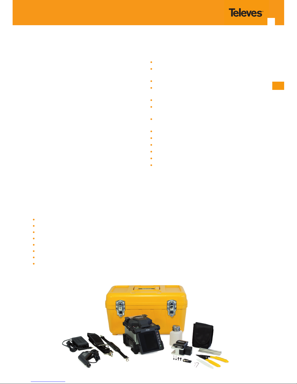
This professional fusion splicer includes 6 alignment engines to work on the dierent axes (X, Y, Z), and thus automatically achieve an electric arc fusion in as little as 8 seconds.
Manufactured in high-resistance ABS, its transport case not
only provides for the equipment transport, but also for the
operator's work desk.
Light and compact, it includes all the required accessories.
Its dimensions, weight and 360o protective dome (highdensity bumper), make this fusion splicer the appropriate
equipment for any type of installations.
Designed for use in hostile environments, it withstands
high-speed winds and other adverse environmental conditions, is water-resistant, and ensures an unparalleled quality throughout the splicing process.
Its user interface is simple and intuitive.
Capable of measuring the cutting angle (identifying potential bad adjustments of the cutter) and detecting bre
errors (usually dirt), it allows the detection of problems before the fusion takes place.
Thanks to a traction process for the verication of the spliced bre and to the calculation of optical loss, it helps the
operator ensure the fusion was performed correctly.
Thanks to its battery (interchangeable from the outside), it
allows working in places lacking VAC power supply. This is
complemented with a feature that allows working with the
fusion splicer while the battery is charging.
Types of bre the fusion splicer can work with:
SM (Single-mode): Single mode (G .652 / G .657)
MM (Multi-mode): Multimode (G .651)
DS (Dispersion): (G .653)
NZDS (non- zero dispersion): (G.655)
BIF/UBIF SM
Standard working diameter: 80 to 150 microns.
External coating diameter: 100 to 1000 microns.
Fibre cleaved length: 5 to 20 mm (standard: 16mm).
Accessories included with the fusion splicer
Carrying case.
Handle for the fusion splicer and carrying strap for the
case.
CD with user manual and software for data download.
Optical bre cleaver with removable pick-up feature,
and ES blade for up to 16.000 cuts.
Precision stripper, pre-calibrated for 125, 250 and 900 μm.
Power cord, power supply and car adapter (the latter in-
cludes USB output to feed other devices).
User-removable lithium battery with charge level visual
indicator.
Isopropyl alcohol tank with dispenser.
Plastic tweezers.
Mount for bre protection cooling.
One spare electrode set (2 items).
One spare pusher set (2 items).
One extra head for precongured connector splicing.
ES
Page 6
6
2. Fusionadora
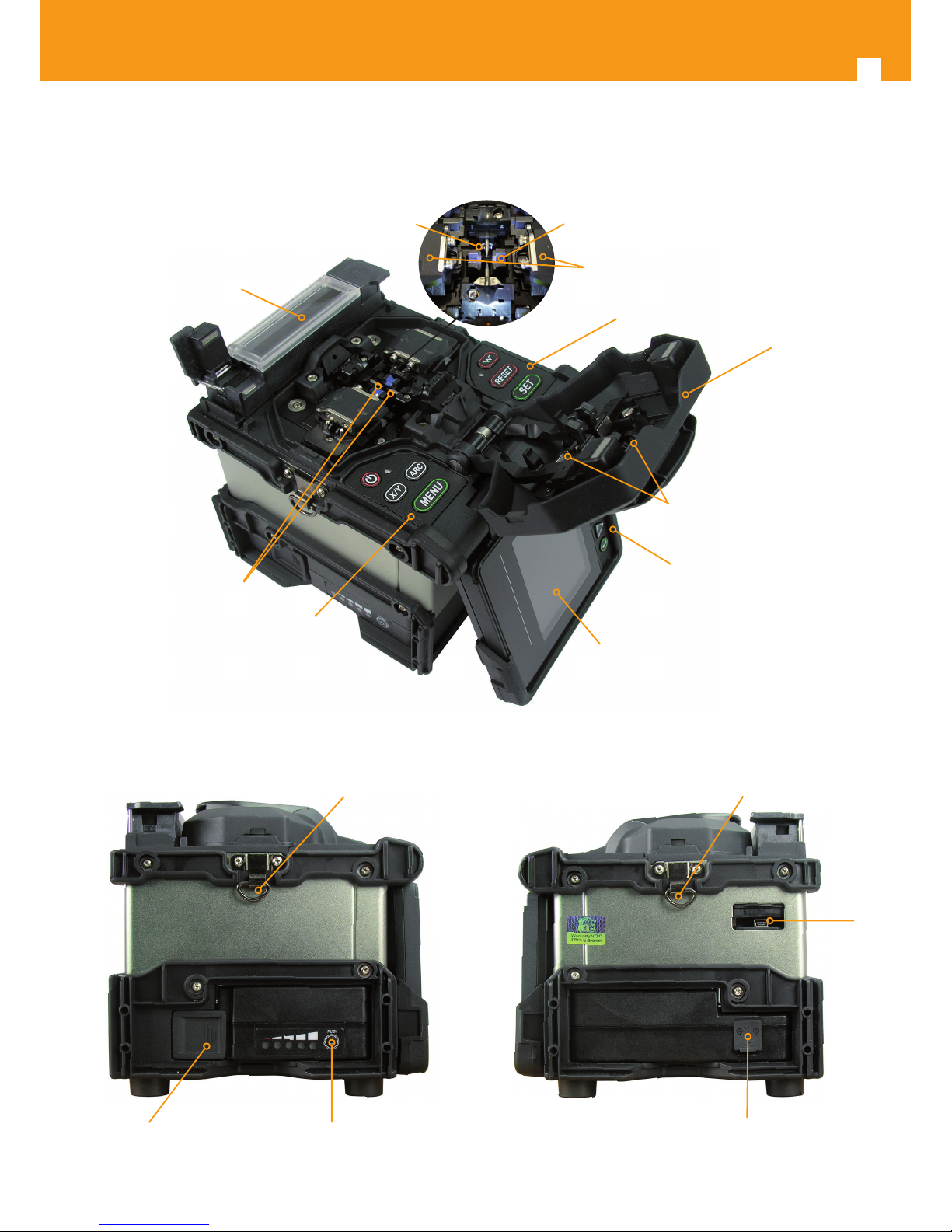
2. 2. Fusion splicer
Front view:
Side views:
Keyboard 2
Cover
Lashing
eyelet
LCD screen
Keyboard 3
Unlock mechanism for
battery release
Battery indicator
push-button
Lashing
eyelet
Power supply
connector
USB
port
Keyboard 1
Oven
Fibre clamps
Electrodes
V- Groove x2
Camera (lens) x2
Mirrors
Page 7
7
ES
3. keyboard
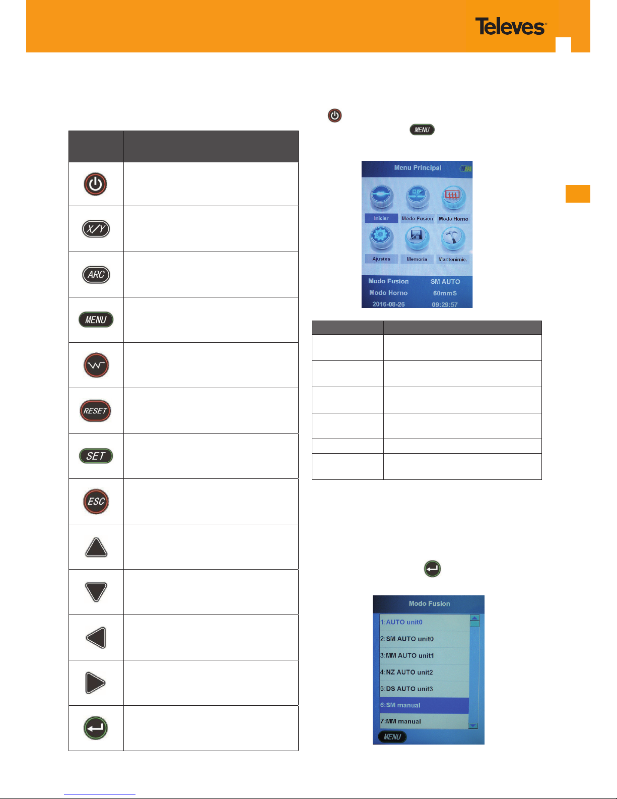
The keyboard operation will depend on the current
working mode. See the table below:
Button Main functions
Equipment Switch on / Switch o (press
and hold).
Change the plane displayed on the screen
(X/Y).
Perform test arc or re-arc.
Access menu and sub-menus.
Oven start-up.
Exit the menu ad get the engines back to
their initial position.
Perform splicing (when bres are positioned).
Perform splicing (when bres are positioned).
Move up.
Move down.
Move left.
Move right.
Conrm and access sub-menus.
4. Commissioning and menu description
To switch the fusion splicer on or o, press and hold the
key
.
Once switched on, press to access the “Main menu”.
Once there, you will be able to access the dierent congurations.
Options Description
Start
You need to access this menu to perform the splicing.
Splicing mode
Selection of bre type and working
mode.
Oven mode
Selection of bre type and working
mode.
Settings
Equipment conguration: language,
screen, power. . .
Memory Displays fusion data and images.
Maintenance Menu for use-based maintenance.
4.1 Start
For the equipment to perform the fusion, you need to
select this option.
4.2 Splicing mode
Scroll through the main menu until you reach the "Fusion
mode" option and press the
button to access it.
Page 8
8
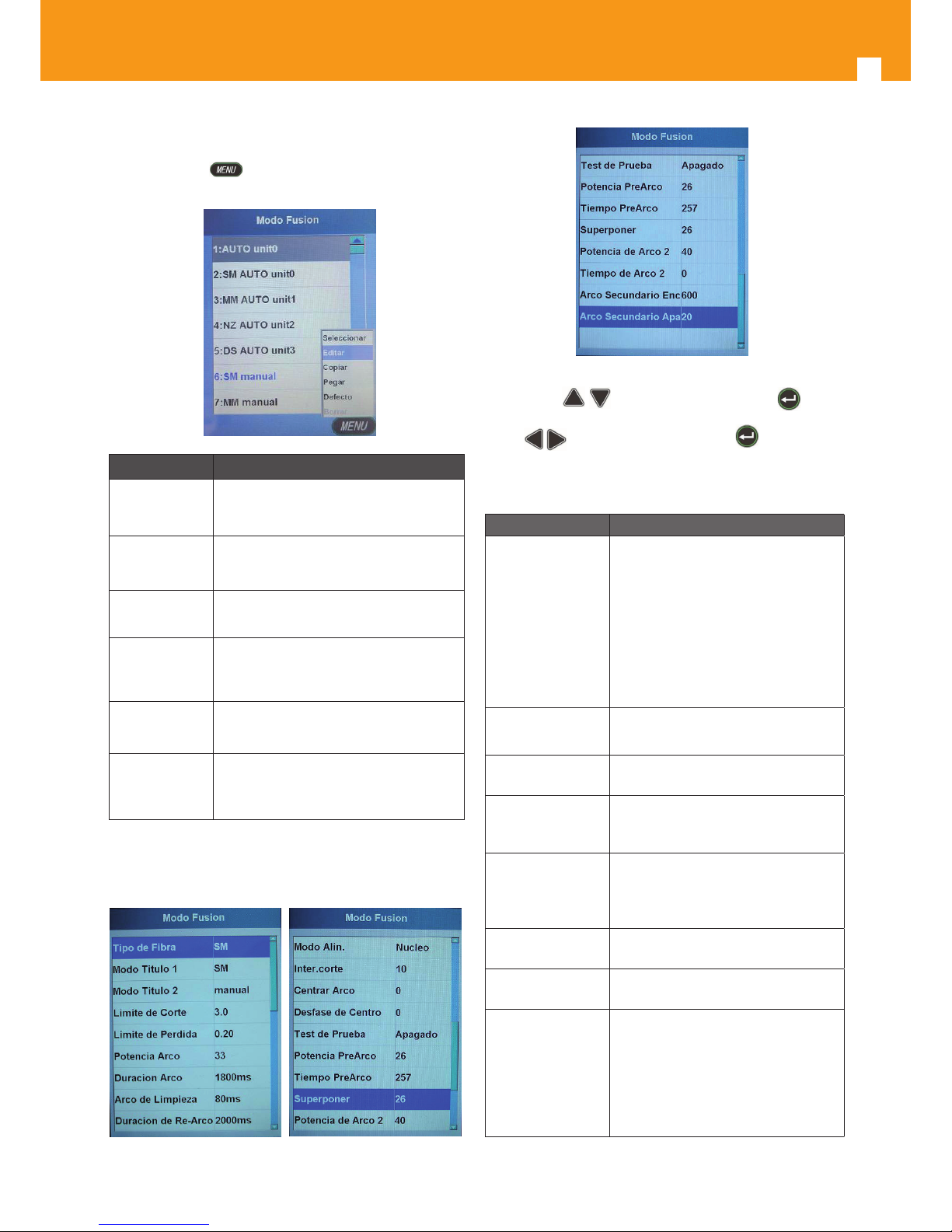
You can select the desired fusion option among the predened options. To do this, move to the desired option and
push the button . The screen will display the following
options:
Parameter Description
Select Sets the selected splicing mode.
Edit
Edits the parameters for the selected
Splicing Mode.
Copy
Copies the selected Splicing Mode
conguration.
Paste
Pastes the previously saved conguration (Copy) on a new register.
Default
Restores the default conguration for
the selected Splicing Mode.
Delete
Deletes the selected Splicing Mode.
(Deleting the factory pre-set modes is
not allowed).
To modify the “Splicing mode” parameters, you should select the “Edit” option on one of the splicing modes, which
will give you access to the following parameters:
To edit any of the parameters you will have to select it with
the bottons
and then push the button to ac-
cess the adjustments. You can change the value by means
of the
buttons and then push the button again
to save the changes.
Parameter description:
Parameter Description
Fibre type
Allows you to select 11 dierent
types of bre/splicing. If you are not
working with any of the pre-dened
options, you should copy one of
them and paste it into an empty
register; you can then modify the
dierent parameters as you wish.
The equipment is factory-congured
with the “Manual” option.
Title 1 Mode
Edits the rst title, with up to 9
characters.
Title 2 Mode
Edits the second title, with up to 8
characters.
Cutting angle
limit
Maximum bre angle error accepted
by the fusion splicer. The factory
pre-set value is 3°.
Loss limit
Acceptable loss value.
Values above the set value will be
considered unsuitable.
The factory pre-set value is 0.10dB.
Electric arc power
Default value is 40. (Only congurable in Manual modes).
Electric arc
duration
Default value is 1500-1800ms. (Only
congurable in Manual modes).
Cleaning arc
Prior to the splicing operation, the
fusion splicer does a "pre-arc" to
eliminate any impurities that could
be present on the bre. With this
option, you can modify the duration
of the cleaning operation (default
value: 80ms).
Page 9
ES
9
Enhanced arc
duration
With this function, the enhanced
duration of the arc can be modied
(usual value: 2000ms). This value can
be increased in case a narrowing is
detected on the bre at the splicing
spot. If the bre is thicker on that
spot (forms a bulge), the value can
be reduced. These values are seldom
modied.
Align. mode
This is the method used by the fusion splicer to align the bres (core
or coating). Always congured with
"Core" mode.
Cutting Inter.
Space that exists between both bres at the alignment and pre-fusion
moment (in μm).
Centre arc
This option is used to move the arc
spot. Default value is 0.
Centre oset
Sets the relative position of the
fusion spot, taking the electrode
centre as a reference. It can be "Centred", if the value remains
0, or moved to the right (+ value) or
to the left (- value) of the electrode
position.
Test
Once the fusion completed, the
fusion splicer applies a 2N strain on
the spliced bre to ensure the result
of the fusion is robust and rm.
Pre-arc power Pre-arc discharge duration (in ms).
Pre-arc duration Pre-arc discharge power (in ms).
Overlap
Mounting or pushing a bre on top
of another at fusion time (in μm).
It controls the thickness of the bre
at the fusion spot, once the splicing
is done.
Power Arc 2
Discharge power of the backup arc
or 2nd arc.
Duration Arc 2
Discharge duration for the backup
arc or 2nd arc.
Secondary arc
Switch on
Pulse (μs). Never modify its value.
Secondary arc
Switch o.
Switch o pulse (μs). Never modify
its value.
4.3 Oven mode.
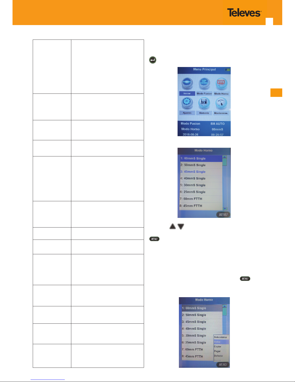
This mode allows you to select of the type of tube or heatshrink sleeve you will be working with. To do this, push the
button once you reached the "Oven mode" menu.
You will access the following sub-menu:
Using the keys, scroll to select the tube type you
wish to work with. Once over the desired option, push the
key to display the option drop-down menu. Check
the "Select" option to set it. Most common tubes are
“60mmS” and “45mmS Single”. All options on the menu
Single are factory pre-congured; however, you will always
be able to adjust them to meet your specic needs or create new options.
To modify the options, follow the steps below:
Go to the tube you wish to modify and push the button. A drop-down sub-menu will be displayed, showing
the dierent options. Select the “Edit” option:
Page 10
10
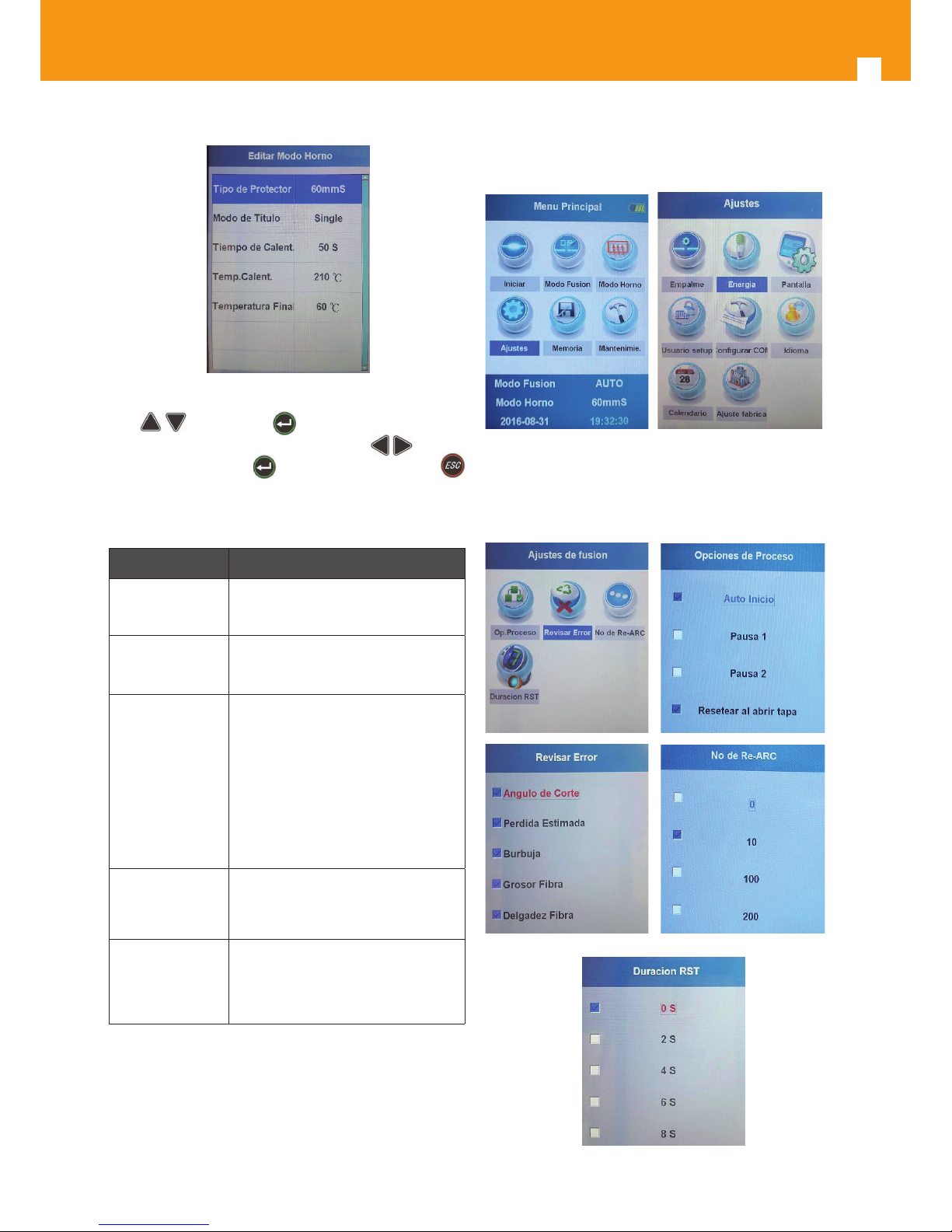
The following sub-menu will be displayed:
To modify the required parameter, go to the desired option
with
and push the key . A window will pop-up
for you to enter the desired value using the
buttons.
Push the save button
again and exit. Push the
button to exit the menu.
Below you will nd a list of the editable parameters:
Parameters Description
Protection type
Type of tube for which the oven is
set (up to 6 characters).
Title mode
Edits the bre type (up to 10 characters).
Heating type
Programming the number of seconds the oven will be on. Despite
the operation range being adjustable in a 10 to 250 second range, programming operation durations over
100 seconds is not recommended
(it considerably reduces the oven's
operating lifetime).
Heating temp.
Sets the maximum heating temperature. Congurable between 100ºC
and 240ºC.
Final
temperature
Sets the minimum oven switch-o
temperature, once the heating time
is over. Congurable between 60º
and 140º.
You are advised not to perform manual programming of
the oven without appropriate technical support. A combination of excessive temperature and excessive time could
result in oven damage after just a few operations. Keeping
the internal fan "on” (automatic operation) prevents the
oven from reaching excessive temperatures.
4.4 Settings
This option allows you to congure the equipment main
settings.
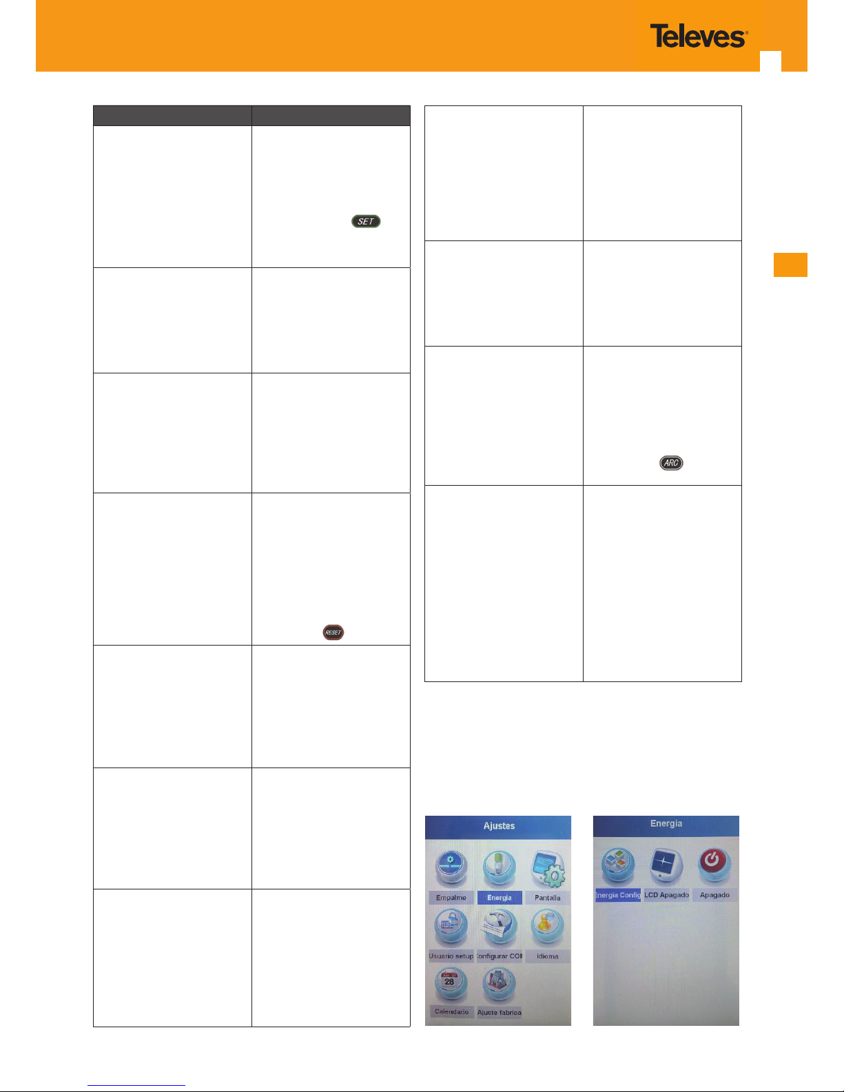
4.4.1 Splicing settings
This option allows you to congure the machine's behaviour during the splicing process.
Page 11
ES
11
Settings Description
Self-start
With this option enabled,
the equipment will start
splicing as soon as the
cover is closed. With this
option disabled, you will
need to push the
button to perform the
splicing process.
Pause 1
With this option checked,
the equipment will pause
after the rst time bres
are brought together.
Pause 2
During the splicing
process, the equipment
will pause again after the
bres are correctly aligned
and before the arc for the
fusion is activated.
Reset on cover opening
With this option enabled,
the equipment will bring
the heads back to their
initial position once the
splicing has been carried
out and after the cover has
been opened. With this option disabled, you will need
to press the
button.
Cutting angle
With this option enabled,
the fusion splicer checks
the bre's cutting angle to
verify whether the value
exceeds the factory-set
acceptable value (3°).
Pérdida estimada
Si tiene esta opción activada, la fusionadora revisa si
el valor de pérdida tras la
fusión es menor o mayor al
programado como aceptable (valor de fábrica 0,10
dB).
Estimated loss
With this option enabled,
the fusion splicer checks
whether the value of the
loss after splicing is lower
or higher than the factoryset acceptable value (0.10
dB).
Blister
With this option enabled,
the fusion splicer will
display an error whenever
blisters are detected in the
fusion area, either due to
external elements or to a
bad adjustment of the arc
discharge.
Fibre thickness
With this option enabled,
the fusion splicer will
display an error whenever
the thickness of the spliced
bre exceeds the standard
thickness.
No. of Re-arcs
Sets the number of
repeated arcs that can be
carried out for a single
splicing after the rst arc.
This repeated arc is usually
carried out manually by
pushing the
button.
RST duration
Sets the delay for engine
restoration and tensile test.
The value “0” indicates the
engines are restored immediately after the cover
is opened. The value “2”
indicates the engines will
be restored 2 seconds after
the cover is opened.
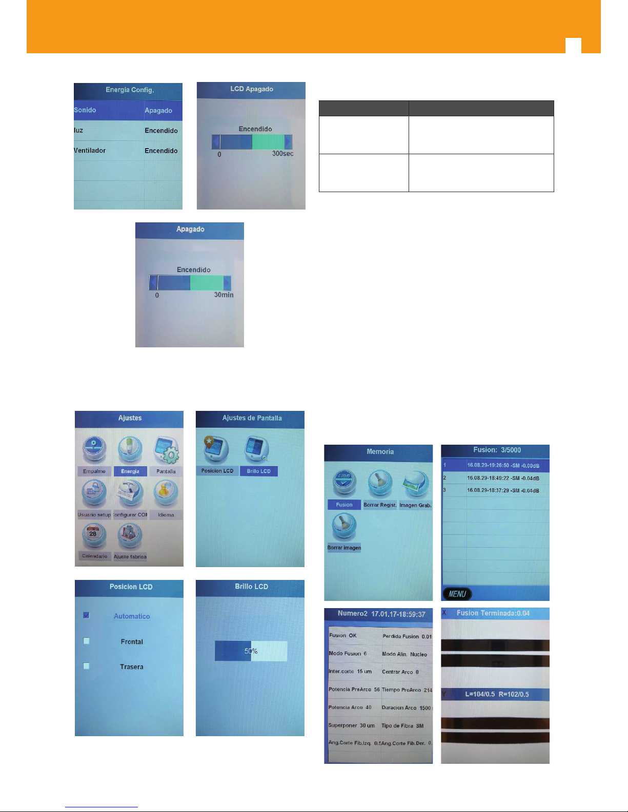
4.4.2 Power settings
This option allows you to congure the equipment power
values in order to manage power and optimize battery use.
You will be able to enable/disable the keyboard sound, the
inner light and the fan, and delay both the LCD screen and
the splicer switch o.
Page 12
12
4.4.3 Screen settings
It allows you to congure the LCD screen orientation and
brightness.
‘
If the LCD position is left on automatic mode, whenever the
screen is tilted the image orientation will adapt automatically.
4.4.4 Access and communication settings
Parameters Description
User set-up
This option allows you to access
the "User" menu. Factory-set password is “AAAAAAAA”.
Congure COM
This option allows you to congure the Baud rate value. Factory-set
value is 11,500.
4.4.5 Language
This option allows you to congure the language. Available
languages are Spanish and English.
4.4.6 Schedule
This option allows you to congure the equipment's date
and time (they will be displayed at data download).
4.4.7 Factory settings
This option allows you to go back to the factory-set values
for all the parameters of the fusion splicer. In case you perform an equipment update, you need to go back to the factory-set values on this menu. Use the password AAAAAAAA
to access the menu.
4.5 Memory
This option allows you to register and manage the splicing
operations' data and pictures saved on the equipment.
Page 13
ES
13
Setting Description
Splicing
his option allows you to access the splicing register to check the values of each
splicing operation.
The fusion splicer allows registering up
to 5,000 splicing operations. You can
download the data with the “OptionFiberFusing .exe” programme.
Delete Reg.
This option allows you to delete all the
existing registers.
Saved Images
This option allows you to access the
register containing the saved fusion
images. You can download these images with the “OptionFiberFusing .exe”
Delete image
This option allows you to delete all the
existing fusion images.
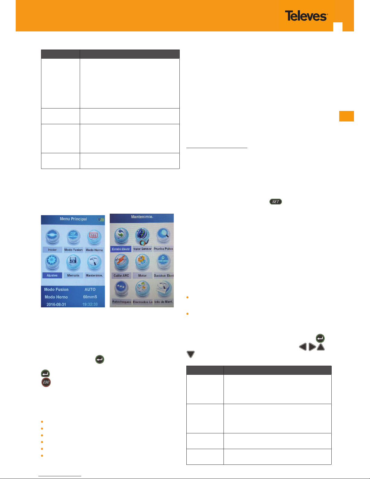
4.5 Maintenance
This option allows you to tune the fusion splicer, adjusting
the values shown in the image below:
4.6.1 Electrode stabilisation.
This menu should be executed whenever the electrodes
are replaced or cleaned. The fusion arc produced by the
equipment will thus be stable and constant.
To carry out this process you only need to access the “Electr.
Stab.” menu, push the
, button , wait until the equip-
ment completes at least 5 test arcs, and push the button
again to stop the process. To quit this menu, push the
button.
4.6.2 Sensor values
This menu allows you to display the values of the sensors
included in the equipment.
Internal temperature
Pressure
Oven temperature
DC Voltage
Elevation
Time
4.6.3 Dust test
This menu allows you to check whether cleaning the lenses
is required
4.6.4 Arc calibration.
You should perform an arc calibration whenever you detect
that splicing operations result in an incorrect nish or were
not actually performed. This action will help the fusion splicer automatically adjust the arc power, based on the environmental variables (temperature, atmospheric pressure,
etc.) and the type of bre used (despite all bre types being
manufactured to a standard, you must take the tolerances
into account).
Arc calibration procedure:
1 To perform the arc calibration, you need to have pre-
viously selected on "Splicing mode“ the bre type you
wish to calibrate the splicer for.
2 Once the bre selected, access the “ARC Calibr." menu.
3 Strip, clean and cut 2 bres, just as if you were going to
perform a fusion, and introduce them into the splicer.
4 Close the splicer cover and push
.
5 Fibres will align and the calibration process will start.
6 Once the process completed, the splicer will display “Co-
rrect Cal.” if the calibration was successful. Conversely, if
the splicer displays “Cal. Failed”, you will have to repeat
the process until the splicer displays “Correct Cal.”.
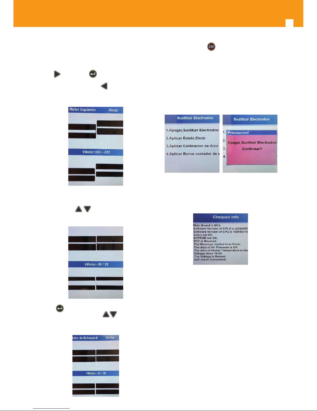
4.6.5 Engine
This menu allows you to readjust the 6 splicer engines
to provide correct bre alignment and focus (core). You
should always execute this function if you nd any of the
following problems when introducing the bres into the
fusion splicer:
Fibres with dierent heights on the LCD screen (not alig-
ned).
I ncorrect thickness of the bre core (too thick).
After accessing the menu, you need to enter the “AA- AAAAAA” password to get the process started. Once there, you
will have to select the dierent engines one by one (
button) to perform the dierent adjustments (
buttons) until you achieve a perfect alignment and fo-
cus.
Engines Description
Left engine
This option allows you to modify the position of the left bre (from left to right for
the X and Y axes, and from top to bottom
for the Y axis).
Right engine
This option allows you to modify the position of the right bre (from right to left for
the X and Y axes, and from top to bottom
for the X axis).
Focus
engine-A
This option allows you to adjust the vision
of the bre (core) on the X axis.
Focus
engine-B
This option allows you to adjust the vision
of the bre (core) on the Y axis.
Page 14
14
Engine adjustment procedure:
After inserting two clean and cleaved bres into the splicer,
start with:
Left engine: Take the bre close to the centre of the screen,
with the
key. Push the button to switch to the right
engine.
Right engine: Then push the
button until the right
bre gets near the centre of the screen, as shown in the following image:
Position the bres in such a way that they almost touch
each other, but not quite.
With the buttons
adjust the height of the bres
to achieve a perfect alignment. You should obtain the following result:
Push the button again to access “focus engine A /B”.
Once there, with the help of the
buttons you need
to achieve the lowest bre-core thickness possible; the result should look like this:
Once done, push the button to complete the procedure.
4.6.6 Change electrodes.
The electrode replacement procedure should be carried
out whenever you detect wearing of the electrodes or any
fusion problems associated with the discharge arc. The
average lifetime of the electrodes is around 3,000 splicing
operations (depending on the working conditions). When
your electrodes are worn out, follow the steps of the following menu:
4.6.7 Self-test
This menu performs an equipment self-test, displaying the
existing rmware versions and the product and sensors' general status.
4.6.8 Electrode limit
This menu allows you to know the number of fusions the
splicer has performed so far, as well as the maximum value
for the electrodes (the latter is programmable by the user).
When changing the electrodes, you will need to reset the
arc counter on this menu.
4.6.9 Maintenance information
This menu displays the splicer's serial number, as well as its
time and date.
Page 15
ES
15
5.Splicing process
5.1 Electrode and element inspection
Make sure there is no trace of bres/dirt on the electrodes,
v-groove, lenses or mirrors. Check the correct alignment of
the electrodes and make sure their ends are in good shape. Should you nd any impurities, take them away with a
wipe/swab dampened with isopropyl alcohol.
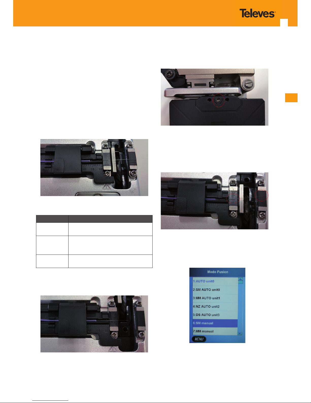
5.2 Fibre preparation
- Strip the bre with the help of a stripper. The stripped
length should be 30 mm to 40 mm. With isopropyl alcohol,
clean any protection residues that may have remained on
the bre and put it on the cleaver (make sure the bre is as
straight as possible between both rubbers).
Depending on the bre type you will be using, you will
need to place the bre in a specic rail, as shown below:
Rail Type of use
Upper rail
For single-bre tubes (3mm thick) or BIF
tubes.
Intermediate
rail
For bres with an initial thickness of
900 microns (see example on the image
below).
Lower rail
For bres with an initial thickness of 250
microns.
- Proceed to cutting the bre with the cleaver. Leave approximately 16mm of bre uncovered after cleavage (see
picture).
In case you were not able to perform the cleaving, check
and make sure that:
1 Both bre protections are correctly removed (900 and
250 microns).
2 The cutting blade is neither worn out nor marked.
3 The cutting blade's height is correct (the blade should
slightly protrude over the bre-holding rubbers) Should
this height be incorrectly set, you can modify it with the
screw.
Make sure that the bre sitting on the cleaver do not form
an angle between both holding rubbers, since it could
cause problems for the fusion (higher cutting angle). Fibre
should sit on both runners, always forming a straight line
between both. The following example illustrates how NOT
to place the bre.
5.3 Fibre type
Switch on the fusion splicer and select the fusion programme based on your bre type. For single-mode bres, the
manual SM mode is pre-set by default.
Page 16
16
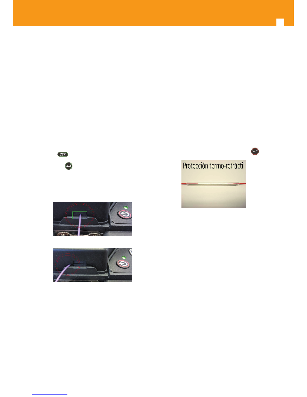
5.4 Fibre introduction into the fusion splicer and
splicing process
- Open the protective cover to place the bre.
- Lift the bre clamps.
- Put the cleaved bres on the V-grooves. Insert them from
top to bottom (avoid bre contact with other elements
present in the fusion splicer).
- Check that bres stick out from the V-groove, and that
they sit half-way between the V-grooves and the electrodes (too close to the electrodes will produce a processing
error). Before closing the cover, make sure that no bre is
seen on the screen. This would mean that the bres are
too close to the electrodes.
- Check that the bres on the V-groove are not misaligned,
since they may be slightly bent.
- Lower the bre clamps and the protective cover; the equipment will start the splicing process.
* If the option “automatic start” is disabled, you will have to
push the key.
Either way, you should have previously entered the “Start”
menu with the
key. The fusion splicer will not work un-
less you are on that menu.
Check the bres hanging from the fusion splicer are not
blocked by the cover or held by the installation (bre should
be loose enough to allow the equipment to move it).
Correct positioning
Incorrect positioning
The splicing process consists on the following steps:
- Fibre positioning.
- Fibre cleaning.
- Adjustment of the distance between bres.
- Fibre-core alignment.
- Electric arc fusion.
- Loss estimation and tensile test.
Should any error display on the screen, the process will stop
until the anomaly is xed.
Should the fusion fail to complete:
1) 1) Check the adjustment of the distance between bres: Despite the fusion splicer automatically bringing the
bres together, it has a minimum and a maximum range.
If the bres are not close enough to each other, the equip-
ment will not be able to bring them together.
2) Check the bres are not dirty: Clean both, bres and
V-groove if necessary.
3) Check the lenses are free of dirt: Lenses need to be
kept clean, since the equipment uses them to align the bres. Some of the fusion errors are due to the presence of
dirt on the lenses. In addition, there are two complementary mirrors on the fusion splicer cover (over the lenses)
that also need to be kept in good condition (clean). See
section 7 (Maintenance).
5.5 Heat-shrink protection
Before you proceed with the process preparation, you need
to introduce a heat-shrink protection on one of the bres to
protect the operation.
After the fusion has taken place, slip the heat-shrink protection along the bre until it fully covers the fusion area. The
process nal step will be to introduce this heat-shrink pro-
tection into the equipment's "OVEN" and hit the
key.
Keep in mind that while the oven's red LED is on, the oven
is near its maximum operating temperature. When this LED
turns o (a beep will be produced), the temperature will
have reached its maximum value, but the process will still
be on-going. Wait until you hear a second beep (indicating
the oven has reached its minimum temperature), to take
the tube out of the oven and place it on the cooler.
It is likely that the equipment's internal fans turn on while
the oven is being used.
This process manages the temperature of the oven's components to enhance durability.
Page 17
ES
17
6. Annexes
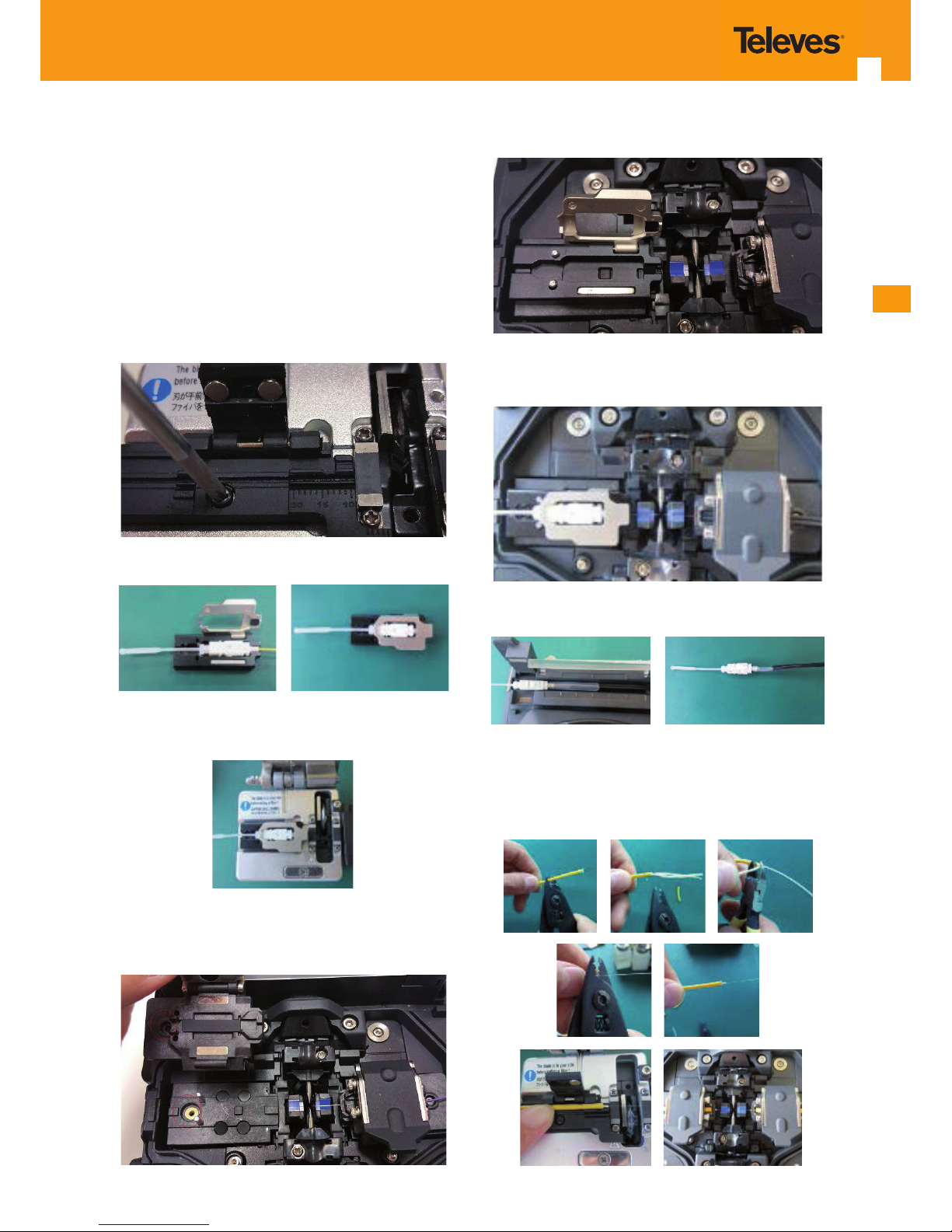
6.1 Annex A (separate head):
Among the fusion splicer's accessories, you will nd a specic head that will allow you to introduce a connector for
direct fusion (these connectors hide the fusion spot under
a cap they have on their rear).
It is conceived to be interchanged with the head coming on
the cleaver and subsequently with one of the bre clamps
existing on the fusion splicer. Follow these steps:
1 Extract the head in the cleaver.
2 Insert the connector on the head.
3 Install the new head on the cleaver (without screw) and
proceed with the cleaving.
4 Exchange the bre clamp of the splicer with the new
head. To do this, extract the bre clamp's screw and remove the clamp, as shown in the image.
5 Install the new head (without screw).
6 Place the bre on the right bre clamp and proceed with
the splicing.
7 Proceed with the baking and mount the connector.
6.2 Annex B (Single-bre tube):
In case you use a single-bre tube (containing only one bre), you can strip it and directly insert it into the cleaver
and the splicer, as shown below:
Page 18
18
6.3 Annex C (BIF-bre tube):
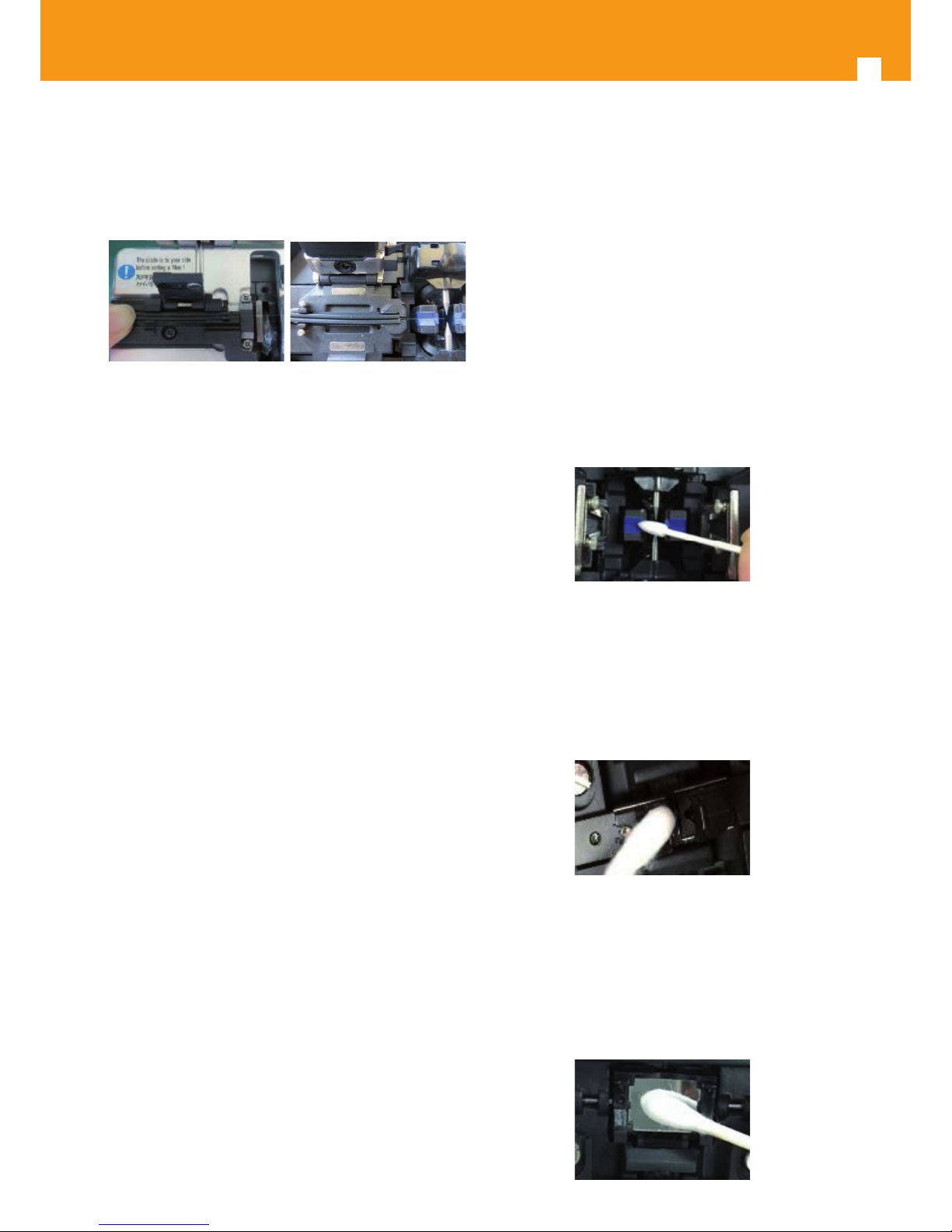
In case you use a BIF-bre tube, you will need to strip it
using a special stripping tool and then insert it into the
cleaver and the splicer, as shown below:
7. Maintenance
7.1 V-groove
Clean the V-groove.
In most cases, fusion high losses are caused by the presence
of contamination (residues/dirt) on the V-groove.
Therefore, you will need to clean both by following the
steps below:
1 Open the protective cover.
2 Clean the V-grooves using specic cleaning swabs (Ref.
232710), dampened with isopropyl alcohol.
3 Should the dirt be adhered, you can use a stripped clean
bre to push it out (put the bre and V-groove forming a
45o angle with each other).
Note: Apply a controlled force for the cleaning of the Vgroove. It is a sensitive precision element.
7.2 Fibre pushers
The equipment includes 2 pushers for bre alignment on
the V-groove. In case of impurities, the risk will increase
of higher losses on the fusion. You should pay special
attention to its cleaning and maintenance. As above, use
a specic cleaning swab (Ref .232710) dampened with
isopropyl alcohol.
7.3 Reecting mirrors
Clean both mirrors regularly.
Presence of contamination (dirt) on any of them will result
in fusion problems or losses higher than usual. For the cleaning, use a specic cleaning swab (Ref .232710) dampened
with isopropyl alcohol. A clean mirror will not have any trace of dirt or ngerprints.
Page 19
ES
19
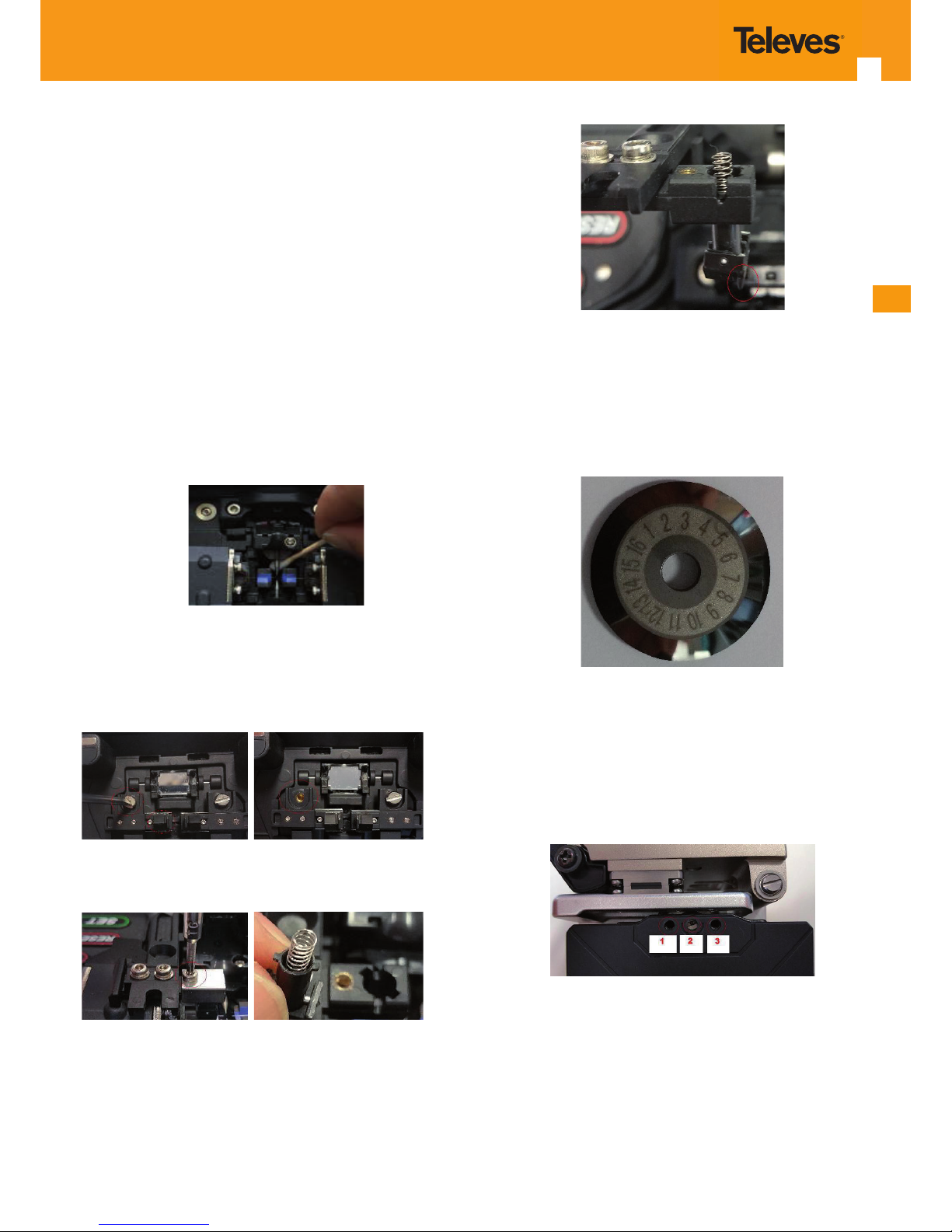
7.4 Cameras or lenses
Clean the lenses regularly.
Presence of dirt on the lenses will result in fusion problems.
Therefore, you should periodically inspect the lenses and clean
them if necessary, by following the steps below:
1 Open the protective cover.
2 Clean both lenses using a specic swab (Ref .232710) dampe-
ned with isopropyl alcohol, by drawing circles progressively
increasing in diameter (start from the centre outwards).
3 Use a dry swab to get rid of possible residues and have the
lenses fully dried.
4 Make sure no residues are left on the surface of the lenses
after cleaning.
Note. During the cleaning, be careful not to push or hit the electrodes. Apply a controlled force (lenses are very sensitive elements). Excessive pressure could result in scratches, that would
make the lenses unusable.
7.5 Pusher substitution
In case a pusher is deteriorated (unusual), you can replace it with
the included spare element. To do this, proceed as follows:
1 Unscrew and remove the screw securing the pusher's body.
2 Extract the screw securing the pusher (take care not to release
the spring underneath).
3 Replace the pusher. Bear in mind that it has a mounting direc-
tion (right or left side) dened by the protrusion shown in the
following image:
Finally, proceed with the assembly, going through the previous
steps in reverse order.
7.6 Changing the cleaver's cutting blade position.
The cleaver's cutting blade has 16 positions. Each position can
execute 1,000 cutting operations, which means 16,000 cuts per
blade.
As long as the cleaver operates correctly, do not modify the
blade's position, even if more than 1,000 cuts have been performed. You should only modify the blade's position if you observe
that despite its height being correct, the blade is not able to cut.
Follow the steps below to modify the blade's position:
1 Loosen Allen screws 1 and 3 as shown in the following gure:
2 Rotate the cutting blade around its axis. To do this:
- Turn the blade by pushing it from the side (not from the edge)
using a tool to avoid being hurt.
- Access it from the top.
- Tighten screws 1 and 3.
Page 20
20
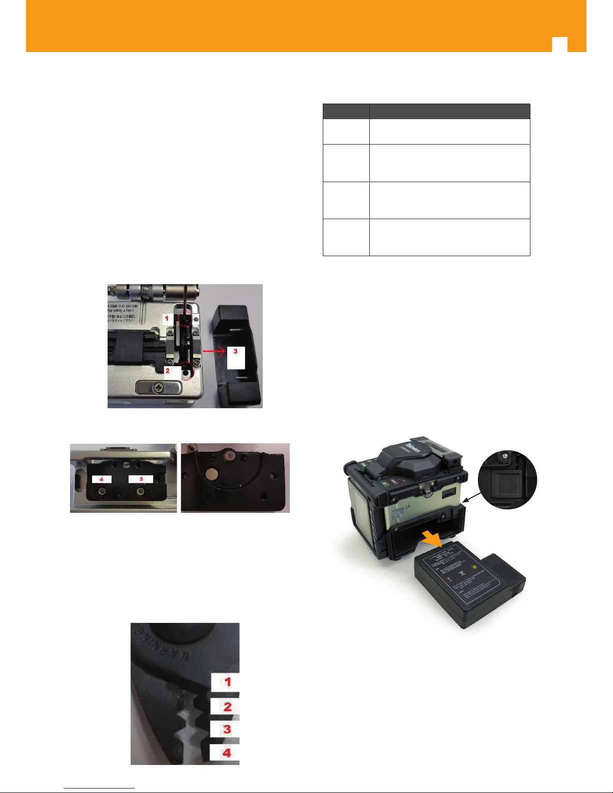
7.7 Adjusting the cleaver's cutting blade height.
By means of a at screwdriver, work on screw no. 2 (shown
in the previous image). Turning the screw to the left will
lower the blade. Turning the screw to the right will raise the
blade.
Upon a blade replacement or a position modication, you
may need to readjust its height. Bear in mind that an excessive blade's height may produce splintering or prevent the
cut.
7.8 Replacing the cleaver's cutting blade.
After 16,000 cuts, you may have to replace the cutting
blade. To do this, proceed as follows:
1 Loosen screws 1 and 2 using an Allen wrench. Next, re-
move lateral protection 3.
2 Remove screws 4 and 5 and extract the blade container.
3 Replace the cutting blade and re-assemble, following
the steps described above in reverse order.
7.9 Stripper
You should occasionally lubricate the stripper's axis to
allow a smooth sliding between both cutting areas. Once
lubricated, remove the excess oil and leave the tool dry.
The stripper has four working zones, as described below:
Position Description
4
Designed for cutting through 900/250
or 125-micron bres.
3
Designed to remove the protection
layer between 3 and 1.6mm, reaching
900 microns.
2
Designed to remove the protection
layer on 900 microns, reaching 250
microns.
1
Designed to remove the protection
layer on 250 microns, reaching 125
microns.
All positions are factory pre-set for a precise operation; therefore, any problems you may nd with the stripping mean
the stripper is worn out and you should replace it. Remember that for a correct stripping, the tool should be tilted
45% in relation to the bre.
7.10 Battery
The equipment comes with an 11.1V, 7,800 mAh battery from factory.
7.10.1 Battery extraction
To remove the battery, push the side button shown on the image.
Note: The battery should only be replaced with a battery of the
same type or equivalent. It should not be exposed to excessive
heat, such as heat from the sun, re or similar.
Recycling: Prior to depositing the appliance at the collection
facility, the user should remove the battery and deposit it in the
specic collection facility for this kind of waste.
Page 21

ES
21
8. Technical specications
Compatible bre
SM, MM,DS,NZDS, BIF.
Typical loss
0,02dB(SM), 0,01dB(MM), 0,04dB(DS),
0,04dB(NZDS), 0,02dB (BIF/UBIF).
Fusion average
duration
9s
Baking average
duration
28s
Alignment method
Core alignment in 3 X-Y-Z axes.
Fusion
programmes
11 (SM, MM, NZ, DS and BIF) pre-congured, 89 free.
Oven programmes
10 pre-congured, 40 free.
Languages
Spanish, English.
Lens magnication
X axis + Y axis = 155x magnication
///X axis or Y axis (separately) = 310x
magnication.
Screen
3,7” colour LCD, 640x480.
Tensile test
2N standard.
Tubes
heat-shrink
60,50,45,40,30 y 25mm.
Electrode duration
3,000 approx. (6,000 with the spare
supplied).
Battery duration
250 fusion/baking cycles, and 300 to
500 load cycles approx.
Internal sensors
Internal temperature, atmospheric
pressure, elevation and oven temperature.
External interface
Mini USB (Up to 5000 Log update and
download).
Power supply unit
Input:100-240V~ 50/60Hz
Output: 13.5V
/5A
Battery type
11.1V 7800 mAh lithium battery.
Working
environment
Temperature: -10ºC... +50°C
Humidity: 95% HR a 40°C RH at 40°C
non-condensing.
Altitude: 0... 5000m
Dimensions
W x H x D in mm: 136x160x164.
Weight
1.8 Kg without battery, and 2.3 Kg
with battery (6.8Kg with case and
accessories).
Page 22

22
Page 23

ES
23
Page 24

televes.com
 Loading...