

Page 1
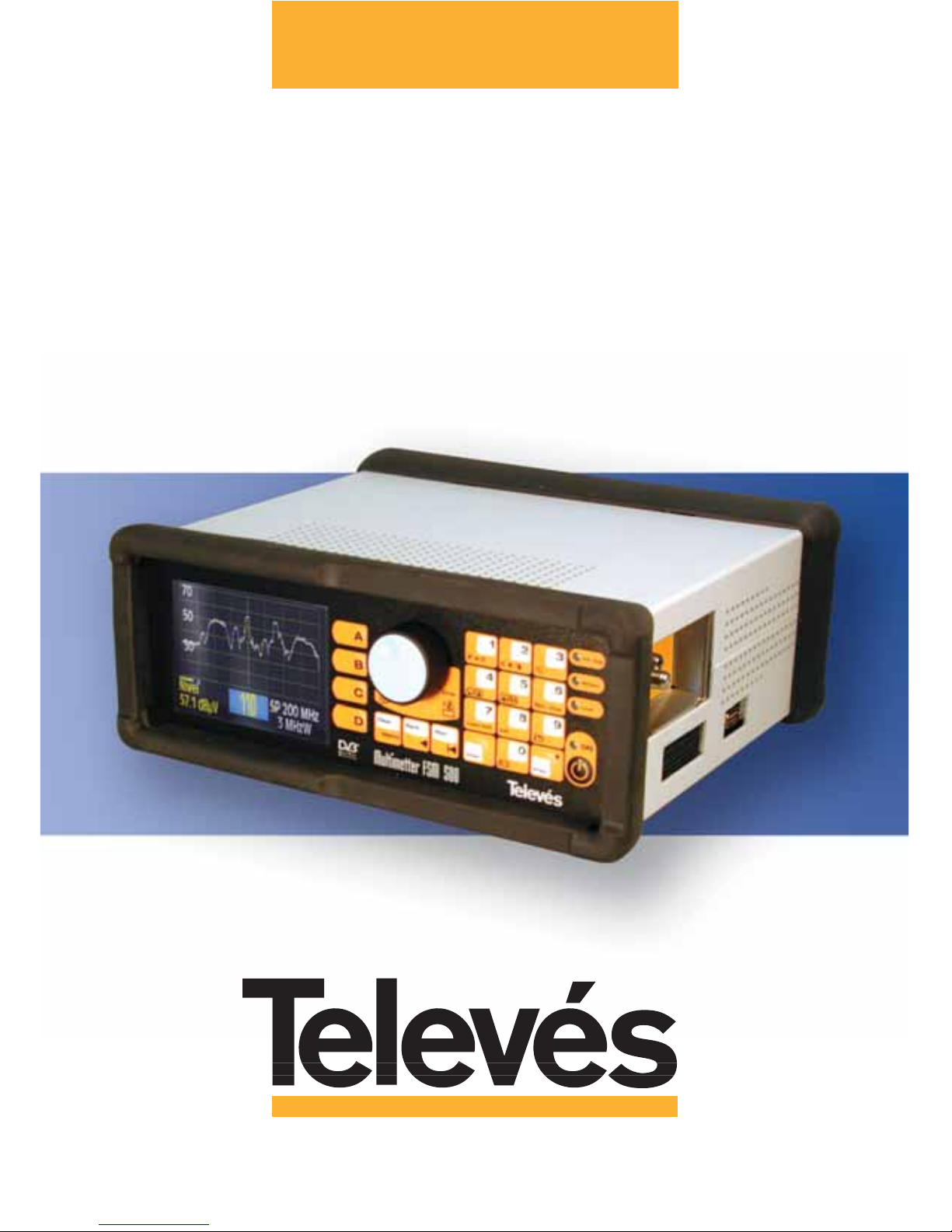
User Manual
Ref. 5903
Field Strength Meter
Multimetter FSM 500
www.televes.com
Page 2

Page 3

Index . . . . . . . . . . . . . . . . . . . . . . . . . . . . . . . . . . . . . . . . . . . . . . . . . . Pg.
1.- INSTALLATION . . . . . . . . . . . . . . . . . . . . . . . . . . . . . . . . . . . . . . . . . . . . . . . . . . . . . . . . . .6
1.1.- Safety measures . . . . . . . . . . . . . . . . . . . . . . . . . . . . . . . . . . . . . . . . . . . . . . . . . . . . . . . . . . 6
1.2.- Power Supply . . . . . . . . . . . . . . . . . . . . . . . . . . . . . . . . . . . . . . . . . . . . . . . . . . . . . . . . . . 7
1.2.1.- External powering . . . . . . . . . . . . . . . . . . . . . . . . . . . . . . . . . . . . . . . . . . . . . . . . . . . . . 7
1.2.2.- Battery powered . . . . . . . . . . . . . . . . . . . . . . . . . . . . . . . . . . . . . . . . . . . . . . . . . . . . . . 7
1.3.- Start-up . . . . . . . . . . . . . . . . . . . . . . . . . . . . . . . . . . . . . . . . . . . . . . . . . . . . . . . . . . 9
2.- PRODUCT DESCRIPTION . . . . . . . . . . . . . . . . . . . . . . . . . . . . . . . . . . . . . . . . . . . . . . . . . . . . . . . . 10
2.1.- Specifications . . . . . . . . . . . . . . . . . . . . . . . . . . . . . . . . . . . . . . . . . . . . . . . . . . . . . . . . . . 11
2.2.- Element description . . . . . . . . . . . . . . . . . . . . . . . . . . . . . . . . . . . . . . . . . . . . . . . . . . . . . . . . . 14
3.- HOW TO USE THE PRODUCT . . . . . . . . . . . . . . . . . . . . . . . . . . . . . . . . . . . . . . . . . . . . . . . . . . . .19
3.1.- The menu . . . . . . . . . . . . . . . . . . . . . . . . . . . . . . . . . . . . . . . . . . . . . . . . . . . . . . . . . . 19
3.2.- Tuning modes . . . . . . . . . . . . . . . . . . . . . . . . . . . . . . . . . . . . . . . . . . . . . . . . . . . . . . . . . . 21
3.3.- Functions . . . . . . . . . . . . . . . . . . . . . . . . . . . . . . . . . . . . . . . . . . . . . . . . . . . . . . . . . . 21
3.3.1.- Measurement configuration . . . . . . . . . . . . . . . . . . . . . . . . . . . . . . . . . . . . . . . . . . . . 22
3.3.1.1.- Band switching . . . . . . . . . . . . . . . . . . . . . . . . . . . . . . . . . . . . . . . . . . . . . . . . . . .22
3.3.1.2.- Preamplifiers/LNB . . . . . . . . . . . . . . . . . . . . . . . . . . . . . . . . . . . . . . . . . . . . . . . . 22
3.3.1.2.1.- LNB . . . . . . . . . . . . . . . . . . . . . . . . . . . . . . . . . . . . . . . . . . . . . . . . . . . . . . . .23
3.3.1.2.2.- DiSEqC . . . . . . . . . . . . . . . . . . . . . . . . . . . . . . . . . . . . . . . . . . . . . . . . . . . . . 25
3.3.1.3.- Channels and Standards . . . . . . . . . . . . . . . . . . . . . . . . . . . . . . . . . . . . . . . . . . . 26
3.3.1.3.1.- Standard . . . . . . . . . . . . . . . . . . . . . . . . . . . . . . . . . . . . . . . . . . . . . . . . . . . . 26
3.3.1.3.2.- Select Plan . . . . . . . . . . . . . . . . . . . . . . . . . . . . . . . . . . . . . . . . . . . . . . . . . . 26
3.3.1.3.3.- Video invertion . . . . . . . . . . . . . . . . . . . . . . . . . . . . . . . . . . . . . . . . . . . . . . . 27
3.3.1.4.- Memory Logger . . . . . . . . . . . . . . . . . . . . . . . . . . . . . . . . . . . . . . . . . . . . . . . . . . . .28
3.3.1.4.1.- Memories . . . . . . . . . . . . . . . . . . . . . . . . . . . . . . . . . . . . . . . . . . . . . . . . . . . 28
3.3.1.4.1.1- Save . . . . . . . . . . . . . . . . . . . . . . . . . . . . . . . . . . . . . . . . . . . . . . . . . . . 29
3.3.1.4.1.2.- Delete . . . . . . . . . . . . . . . . . . . . . . . . . . . . . . . . . . . . . . . . . . . . . . . . . 30
3.3.1.4.1.3.- Edit . . . . . . . . . . . . . . . . . . . . . . . . . . . . . . . . . . . . . . . . . . . . . . . . . . . 30
3.3.1.4.2.- Macromeasurements . . . . . . . . . . . . . . . . . . . . . . . . . . . . . . . . . . . . . . . . . . 32
3.3.1.4.2.1.- New Macro . . . . . . . . . . . . . . . . . . . . . . . . . . . . . . . . . . . . . . . . . . . . . . 37
3.3.1.4.2.2.- Edit Macro . . . . . . . . . . . . . . . . . . . . . . . . . . . . . . . . . . . . . . . . . . . . . . 38
3.3.1.4.2.3.- Edit name . . . . . . . . . . . . . . . . . . . . . . . . . . . . . . . . . . . . . . . . . . . . . . . 38
3.3.1.4.2.4.- Erase Macro . . . . . . . . . . . . . . . . . . . . . . . . . . . . . . . . . . . . . . . . . . . . . 38
3.3.1.4.3.- View Data Logs . . . . . . . . . . . . . . . . . . . . . . . . . . . . . . . . . . . . . . . . . . . . . . 38
3.3.1.4.3.1.- Erase Logs . . . . . . . . . . . . . . . . . . . . . . . . . . . . . . . . . . . . . . . . . . . . . 39
3.3.1.4.3.2.- Edit Logs . . . . . . . . . . . . . . . . . . . . . . . . . . . . . . . . . . . . . . . . . . . . . . . 40
3.3.1.4.4.- Graphs . . . . . . . . . . . . . . . . . . . . . . . . . . . . . . . . . . . . . . . . . . . . . . . . . . . . 40
3.3.1.4.4.1.- Save graphs . . . . . . . . . . . . . . . . . . . . . . . . . . . . . . . . . . . . . . . . . . . . 41
3.3.1.4.4.1.1.- GLOG options . . . . . . . . . . . . . . . . . . . . . . . . . . . . . . . . . . . . . . 42
3.3.1.4.4.1.2.- Edit Name . . . . . . . . . . . . . . . . . . . . . . . . . . . . . . . . . . . . . . . . . 42
3.3.1.4.4.2.- Edit Name . . . . . . . . . . . . . . . . . . . . . . . . . . . . . . . . . . . . . . . . . . . . . . 43
3.3.1.4.4.2.1.- Edit Graph Name . . . . . . . . . . . . . . . . . . . . . . . . . . . . . . . . . . . . 43
3.3.1.4.4.3.- Erase Graph . . . . . . . . . . . . . . . . . . . . . . . . . . . . . . . . . . . . . . . . . . . . 43
3.3.1.4.4.3.1.- Select Graphs . . . . . . . . . . . . . . . . . . . . . . . . . . . . . . . . . . . . . . 43
Multimetter FSM 500 Ref. 5903
3
Page 4

3.3.2.- Equipment configuration . . . . . . . . . . . . . . . . . . . . . . . . . . . . . . . . . . . . . . . . . . . . . . 44
3.3.2.1.- Language . . . . . . . . . . . . . . . . . . . . . . . . . . . . . . . . . . . . . . . . . . . . . . . . . . . . . . . . 44
3.3.2.2.- Automatic shut-down . . . . . . . . . . . . . . . . . . . . . . . . . . . . . . . . . . . . . . . . . . . . . . 45
3.3.2.3.- Monitor . . . . . . . . . . . . . . . . . . . . . . . . . . . . . . . . . . . . . . . . . . . . . . . . . . . . . . . . . 45
3.3.2.3.1.- Volume . . . . . . . . . . . . . . . . . . . . . . . . . . . . . . . . . . . . . . . . . . . . . . . . . . . . . 46
3.3.2.3.2.- Brightness . . . . . . . . . . . . . . . . . . . . . . . . . . . . . . . . . . . . . . . . . . . . . . . . . . 46
3.3.2.3.3.- Contrast . . . . . . . . . . . . . . . . . . . . . . . . . . . . . . . . . . . . . . . . . . . . . . . . . . . . 46
3.3.2.3.4.- Saturation . . . . . . . . . . . . . . . . . . . . . . . . . . . . . . . . . . . . . . . . . . . . . . . . . . . 46
3.3.2.4.- Clock . . . . . . . . . . . . . . . . . . . . . . . . . . . . . . . . . . . . . . . . . . . . . . . . . . . . . . . . . . 46
3.3.2.5.- Scart . . . . . . . . . . . . . . . . . . . . . . . . . . . . . . . . . . . . . . . . . . . . . . . . . . . . . . . . . . 47
3.3.2.6.- Information about the equipment . . . . . . . . . . . . . . . . . . . . . . . . . . . . . . . . . . . . . 48
3.3.2.6.1.- Update . . . . . . . . . . . . . . . . . . . . . . . . . . . . . . . . . . . . . . . . . . . . . . . . . . . . . 48
3.3.2.6.1.- Changing the battery . . . . . . . . . . . . . . . . . . . . . . . . . . . . . . . . . . . . . . . . . . 49
3.3.2.6.3.- Battery regeneration . . . . . . . . . . . . . . . . . . . . . . . . . . . . . . . . . . . . . . . . . . 50
3.3.3.- TV mode . . . . . . . . . . . . . . . . . . . . . . . . . . . . . . . . . . . . . . . . . . . . . . . . . . . . . . . . . . 52
3.3.3.1.- Viewing mode . . . . . . . . . . . . . . . . . . . . . . . . . . . . . . . . . . . . . . . . . . . . . . . . . . . .52
3.3.3.1.1. Bar . . . . . . . . . . . . . . . . . . . . . . . . . . . . . . . . . . . . . . . . . . . . . . . . . . . . . . . . . 52
3.3.3.1.2.- Synchronism . . . . . . . . . . . . . . . . . . . . . . . . . . . . . . . . . . . . . . . . . . . . . . . . 53
3.3.3.1.3.- Measurement windows . . . . . . . . . . . . . . . . . . . . . . . . . . . . . . . . . . . . . . . . 54
3.3.3.1.4.- Teletext . . . . . . . . . . . . . . . . . . . . . . . . . . . . . . . . . . . . . . . . . . . . . . . . . . . . .55
3.3.3.2.- Measurement . . . . . . . . . . . . . . . . . . . . . . . . . . . . . . . . . . . . . . . . . . . . . . . . . . . .55
3.3.3.2.1.- Analogue . . . . . . . . . . . . . . . . . . . . . . . . . . . . . . . . . . . . . . . . . . . . . . . . . . . 56
3.3.3.2.1.1.- Level . . . . . . . . . . . . . . . . . . . . . . . . . . . . . . . . . . . . . . . . . . . . . . . . . . 56
3.3.3.2.1.2.- V/A . . . . . . . . . . . . . . . . . . . . . . . . . . . . . . . . . . . . . . . . . . . . . . . . . . . . 57
3.3.3.2.1.3.- Automatic C/N . . . . . . . . . . . . . . . . . . . . . . . . . . . . . . . . . . . . . . . . . . 58
3.3.3.2.1.3.1.- Channel BW . . . . . . . . . . . . . . . . . . . . . . . . . . . . . . . . . . . . . . . . 60
3.3.3.2.1.4.- Referenced C/N . . . . . . . . . . . . . . . . . . . . . . . . . . . . . . . . . . . . . . . . . 60
3.3.3.2.1.4.1.- Reference frequency . . . . . . . . . . . . . . . . . . . . . . . . . . . . . . . . . 61
3.3.3.2.1.4.2.- Channel BW . . . . . . . . . . . . . . . . . . . . . . . . . . . . . . . . . . . . . . . . 61
3.3.3.2.2.- Digital . . . . . . . . . . . . . . . . . . . . . . . . . . . . . . . . . . . . . . . . . . . . . . . . . . . . . . 62
3.3.3.2.2.1.- Channel power . . . . . . . . . . . . . . . . . . . . . . . . . . . . . . . . . . . . . . . . . . 62
3.3.3.2.2.1.1.- Channel BW . . . . . . . . . . . . . . . . . . . . . . . . . . . . . . . . . . . . . . . . 63
3.3.3.2.2.2.- Automatic C/N . . . . . . . . . . . . . . . . . . . . . . . . . . . . . . . . . . . . . . . . . . 63
3.3.3.2.2.3.- Referenced C/N . . . . . . . . . . . . . . . . . . . . . . . . . . . . . . . . . . . . . . . . . . 63
3.3.3.2.2.4.- BER measurement . . . . . . . . . . . . . . . . . . . . . . . . . . . . . . . . . . . . . . . . 63
3.3.3.2.2.4.1.- COFDM . . . . . . . . . . . . . . . . . . . . . . . . . . . . . . . . . . . . . . . . . . . . 65
3.3.3.2.2.4.1.1.- Parameters . . . . . . . . . . . . . . . . . . . . . . . . . . . . . . . . . . . . . 65
3.3.3.2.2.4.1.2.- Error packets . . . . . . . . . . . . . . . . . . . . . . . . . . . . . . . . . . . 67
3.3.3.2.2.4.1.3.- BER . . . . . . . . . . . . . . . . . . . . . . . . . . . . . . . . . . . . . . . . . . 67
3.3.3.2.2.4.1.4.- MPEG . . . . . . . . . . . . . . . . . . . . . . . . . . . . . . . . . . . . . . . . . 67
3.3.3.2.2.4.2.- QAM . . . . . . . . . . . . . . . . . . . . . . . . . . . . . . . . . . . . . . . . . . . . . . 69
3.3.3.2.2.4.2.1.- Parameters . . . . . . . . . . . . . . . . . . . . . . . . . . . . . . . . . . . . . 69
3.3.3.2.2.4.2.2.- BER . . . . . . . . . . . . . . . . . . . . . . . . . . . . . . . . . . . . . . . . . . 70
3.3.3.2.2.4.2.3.- MPEG . . . . . . . . . . . . . . . . . . . . . . . . . . . . . . . . . . . . . . . . . 70
3.3.3.2.2.4.2.4.- Constellation . . . . . . . . . . . . . . . . . . . . . . . . . . . . . . . . . . . 71
3.3.3.2.2.4.3.- QPSK . . . . . . . . . . . . . . . . . . . . . . . . . . . . . . . . . . . . . . . . . . . . . . 72
3.3.3.2.2.4.3.1.- Parameters . . . . . . . . . . . . . . . . . . . . . . . . . . . . . . . . . . . . . 72
3.3.3.2.2.4.3.2.- Error packets . . . . . . . . . . . . . . . . . . . . . . . . . . . . . . . . . . . 72
3.3.3.2.2.4.3.3.- BER . . . . . . . . . . . . . . . . . . . . . . . . . . . . . . . . . . . . . . . . . . 72
3.3.3.2.2.4.3.4.- MPEG . . . . . . . . . . . . . . . . . . . . . . . . . . . . . . . . . . . . . . . . . 72
Multimetter FSM 500 Ref. 5903
4
Page 5

3.3.3.3.- Channel search . . . . . . . . . . . . . . . . . . . . . . . . . . . . . . . . . . . . . . . . . . . . . . . . . . .73
3.3.3.3.1.- Search level . . . . . . . . . . . . . . . . . . . . . . . . . . . . . . . . . . . . . . . . . . . . . . . . . . 74
3.3.3.3.2.- Next . . . . . . . . . . . . . . . . . . . . . . . . . . . . . . . . . . . . . . . . . . . . . . . . . . . . . . . . . 74
3.3.3.3.3.- Previous . . . . . . . . . . . . . . . . . . . . . . . . . . . . . . . . . . . . . . . . . . . . . . . . . . . . .74
3.3.3.4.- Nicam . . . . . . . . . . . . . . . . . . . . . . . . . . . . . . . . . . . . . . . . . . . . . . . . . . . . . . . . . . 75
3.3.3.5.- Selecting the audio carrier . . . . . . . . . . . . . . . . . . . . . . . . . . . . . . . . . . . . . . . . . . 75
3.3.3.6.- FM radio . . . . . . . . . . . . . . . . . . . . . . . . . . . . . . . . . . . . . . . . . . . . . . . . . . . . . . . . . 76
3.3.4.- Spectrum . . . . . . . . . . . . . . . . . . . . . . . . . . . . . . . . . . . . . . . . . . . . . . . . . . . . . . . . . . 77
3.3.4.1.- Reference level . . . . . . . . . . . . . . . . . . . . . . . . . . . . . . . . . . . . . . . . . . . . . . . . . . . 78
3.3.4.2.- Span . . . . . . . . . . . . . . . . . . . . . . . . . . . . . . . . . . . . . . . . . . . . . . . . . . . . . . . . . . 79
3.3.4.3.- Measurements . . . . . . . . . . . . . . . . . . . . . . . . . . . . . . . . . . . . . . . . . . . . . . . . . . . 80
3.3.4.3.1.- Analogue . . . . . . . . . . . . . . . . . . . . . . . . . . . . . . . . . . . . . . . . . . . . . . . . . . . 80
3.3.4.3.1.1.- Level . . . . . . . . . . . . . . . . . . . . . . . . . . . . . . . . . . . . . . . . . . . . . . . . . . 80
3.3.4.3.1.2.- V/A . . . . . . . . . . . . . . . . . . . . . . . . . . . . . . . . . . . . . . . . . . . . . . . . . . . . 80
3.3.4.3.1.3.- Automatic C/N . . . . . . . . . . . . . . . . . . . . . . . . . . . . . . . . . . . . . . . . . . 81
3.3.4.3.1.4.- Referenced C/N . . . . . . . . . . . . . . . . . . . . . . . . . . . . . . . . . . . . . . . . . . 81
3.3.4.3.1.4.1.- Reference frequency . . . . . . . . . . . . . . . . . . . . . . . . . . . . . . . . . 82
3.3.4.3.1.4.2.- Channel BW . . . . . . . . . . . . . . . . . . . . . . . . . . . . . . . . . . . . . . . . 82
3.3.4.3.2.- Digital . . . . . . . . . . . . . . . . . . . . . . . . . . . . . . . . . . . . . . . . . . . . . . . . . . . . . . 83
3.3.4.3.2.1.- Channel power . . . . . . . . . . . . . . . . . . . . . . . . . . . . . . . . . . . . . . . . . . 83
3.3.4.3.2.1.1.- BW Canal . . . . . . . . . . . . . . . . . . . . . . . . . . . . . . . . . . . . . . . . . . 83
3.3.4.3.2.2.- C/N automática . . . . . . . . . . . . . . . . . . . . . . . . . . . . . . . . . . . . . . . . . . 84
3.3.4.3.2.2.1.- Channel BW . . . . . . . . . . . . . . . . . . . . . . . . . . . . . . . . . . . . . . . . 84
3.3.4.3.2.3.- Referenced C/N . . . . . . . . . . . . . . . . . . . . . . . . . . . . . . . . . . . . . . . . . 84
3.3.4.3.2.3.1.- Reference frequency . . . . . . . . . . . . . . . . . . . . . . . . . . . . . . . . . 84
3.3.4.3.2.3.2.- Channel BW . . . . . . . . . . . . . . . . . . . . . . . . . . . . . . . . . . . . . . . . 84
3.3.4.4.- Markers . . . . . . . . . . . . . . . . . . . . . . . . . . . . . . . . . . . . . . . . . . . . . . . . . . . . . . . . . 85
3.3.4.4.1.- Second marker . . . . . . . . . . . . . . . . . . . . . . . . . . . . . . . . . . . . . . . . . . . . . . 85
3.3.4.4.2.- Changing markers . . . . . . . . . . . . . . . . . . . . . . . . . . . . . . . . . . . . . . . . . . . . 85
3.3.4.5.- RBW . . . . . . . . . . . . . . . . . . . . . . . . . . . . . . . . . . . . . . . . . . . . . . . . . . . . . . . . . . 86
3.3.4.6.- Hold (On/Off) . . . . . . . . . . . . . . . . . . . . . . . . . . . . . . . . . . . . . . . . . . . . . . . . . . . . . . 87
3.4.- Error warnings . . . . . . . . . . . . . . . . . . . . . . . . . . . . . . . . . . . . . . . . . . . . . . . . . . . . . . . . . . 88
4.- DESCRIPTION OF THE INPUTS AND OUTPUTS . . . . . . . . . . . . . . . . . . . . . . . . . . . . . . . . . . . . . 90
4.1.- RF input . . . . . . . . . . . . . . . . . . . . . . . . . . . . . . . . . . . . . . . . . . . . . . . . . . . . . . . . . . 90
4.2.- RS-232C serial port . . . . . . . . . . . . . . . . . . . . . . . . . . . . . . . . . . . . . . . . . . . . . . . . . . . . . . . . 90
4.3.- SCART connector . . . . . . . . . . . . . . . . . . . . . . . . . . . . . . . . . . . . . . . . . . . . . . . . . . . . . . . . . . 91
5.- MAINTENANCE . . . . . . . . . . . . . . . . . . . . . . . . . . . . . . . . . . . . . . . . . . . . . . . . . . . . . . . . . . 92
5.1.- Replacing the batteries . . . . . . . . . . . . . . . . . . . . . . . . . . . . . . . . . . . . . . . . . . . . . . . . . . . . . . 92
5.2.- Cleaning instructions . . . . . . . . . . . . . . . . . . . . . . . . . . . . . . . . . . . . . . . . . . . . . . . . . . . . . . . 94
APPENDIX 1.- Batteries . . . . . . . . . . . . . . . . . . . . . . . . . . . . . . . . . . . . . . . . . . . . . . . . . . . . . . . . . .95
APPENDIX 2.- Channel plans . . . . . . . . . . . . . . . . . . . . . . . . . . . . . . . . . . . . . . . . . . . . . . . . . . . . . . . 96
Multimetter FSM 500 Ref. 5903
5
Page 6
1.- INSTALLATION
1.1.- SAFETY MEASURES
- The non-specified use of the equipment does not ensure its safety.
- The external DC adapter is class I equipment, so for safety reasons it should be
connected to a supply line with the corresponding ground terminal.
- This equipment can be used in installations with Overvoltage Category II and in
environments with Pollution Degree 2.
- When using any of the following accessories, it is necessary to use only those types
specified for reasons of safety:
Rechargeable battery
External DC adapter
- Always take the specified margins into account both for the power supply as well as for
the measurements.
- Remember that any voltages above 60 V DC or 30 V AC rms are potentially dangerous.
- Always check the specified maximum environmental conditions for this equipment.
- The user is only authorised to:
Replace the batteries.
The Maintenance section provides specific instructions for this type of service.
Any other modification in the equipment should be carried out by specialised personnel
only.
- The negative of measurement is at ground potential.
- Do not obstruct the equipment’s ventilation system.
- Use the appropriate cables with low radiation levels (for example, Televés’ T100) for the
signal inputs/outputs, especially when using high levels.
- Follow the cleaning instructions described in the Maintenance section.
Multimetter FSM 500 Ref. 5903
6
SAFETY MEASURES
Before using the equipment, read the user manual and read the section on
SAFETY MEASURES.
The symbol on the equipment indicates: “SEE USER MANUAL”.
This manual may also contain the Caution or Warning symbols.
CAUTION AND WARNING messages may appear in this manual in order to avoid
the risk of accidents or to avoid causing damage to the equipment or to other property.
Page 7
1.2.- POWER SUPPLY
The FSM 500 has two operation modes; external powering or battery powered.
1.2.1.- Alimentación externa
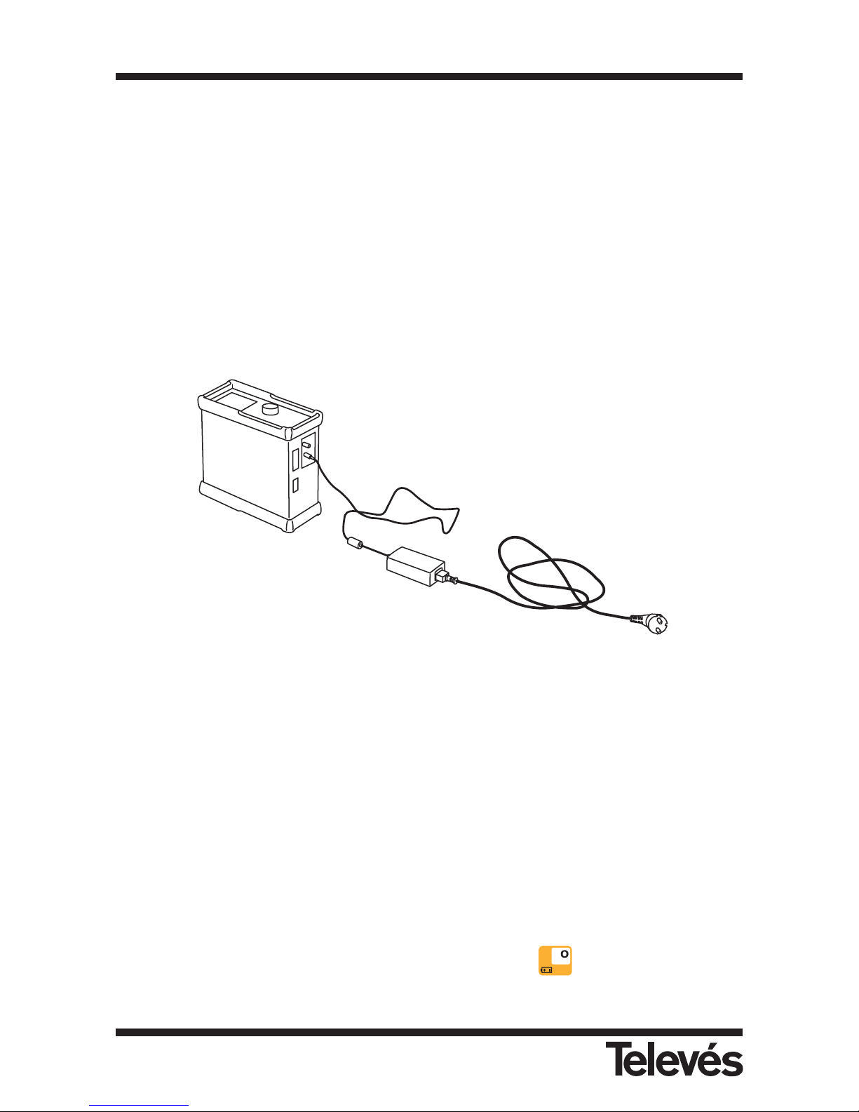
A DC adapter is provided with the equipment which allows you to connect the equipment to the
mains, both for normal operation as well as for charging the batteries. There is a special
compartment for it in the cover. To connect the equipment to the mains, connect the adapter
to the power connector (13) located on the side of the equipment (see 2.3.- Element
description).
When the equipment is connected to the mains, the Ext. Sup. LED (11) lights up (see 2.3.Element description).
Figure 1.- Connection to the mains
1.2.2.- Battery powered
The FSM 500 comes with one 12V Ni-MH battery. This battery, using an average consumption,
can power the equipment for more than four hours.
The equipment features a complicated control system for charging and discharging the
batteries which optimises their duration and life, and this in turn means that the equipment can
use this form of powering without any abrupt decrease in the length of time.
To charge the batteries, connect the equipment to the mains using the DC adapter (see
previous section). If the batteries have less than 40% of their optimal power, the recharging
process will begin automatically.
However, the battery can be charged even if it has more than 40% of its optimal power by
simply plugging the equipment into the mains and pressing the button for 3 seconds. To
stop charging, press the same button again for 3 seconds.
Multimetter FSM 500 Ref. 5903
7
Page 8

While the equipment is charging the battery, the Battery (11) LED will flash.
In any case, the equipment will stop charging once this is complete.
The equipment is constantly monitoring the status of the batteries and it informs the user of
their status via an LED icon (Battery (11)) and an audio signal.
The icon is a battery with a blue outline. When the batteries are fully charged, the inside part of
the battery icon is completely yellow. As the battery discharges, the level of the yellow colour
drops leaving the rest of the battery icon empty (transparent). The icon has 5 different levels,
which represent the approximate status of the battery:
- Batteries charged <20% (icon totally empty)
- Batteries charged between 20 and 40%
- Batteries charged between 40 and 60%
- Batteries charged between 60 and 80%
- Batteries charged >80% (icon totally full)
The LED indicates the state of the batteries during the recharging process: when the equipment
is connected to the mains, if the batteries are more than 40% full, they will not get charged
(unless the recharging process is forced).
If the batteries are less than 40% full, the recharging process will begin. When the batteries are
<20% full, the LED will light up for 500 msecs and will switch off for 2.5 secs. As they get
recharged, the time that the LED is on will increase and the time that it is off will decrease. When
the batteries are 80% full, the LED will light up for 2.5 secs and will switch off for 500 msecs.
When they are completely full, the LED will remain on until the equipment is used.
Note: If the temperature is too high, the charging process will not begin, and if this process
is already underway, when the temperature reaches a certain level, the process will stop
and will start again once the temperature has returned to an appropriate level
When the external powering is disconnected, the LED will turn itself off.
If the batteries get below a certain level, the equipment will begin to make a buzzing noise and
a message will appear onscreen indicating a low battery. If the battery level continues to drop,
the equipment will indicate this every 10 seconds, warning you that it will shut down unless you
connect it to the external powering before 30 seconds have passed. If this is not carried out,
the equipment will shut down.
On the equipment’s information screen (see 3.3.2.6.- Information about the equipment) you can
also see information about the voltage of the batteries.
Note: When the battery has run out completely, the recharging process will take about
10 hours if the equipment is switched off during the entire process. If the
equipment is on, the ssame process will take about 18 hours.
Multimetter FSM 500 Ref. 5903
8
Page 9
Note on charging the battery:
=> Whenever possible, it is advisable to recharge the batteries completely. In other words,
when the recharging process begins, do not interrupt it, until the batteries are 100% full.
=> If you are not going to use the equipment for a while, the battery level should not be very
low. The batteries will discharge slowly while the equipment is not in use, therefore it is
advisable to carry out a recharging process every 2 or 3 months if the batteries are stored
in a room temperature of 25ºC. The higher the room temperature, the more frequent the
recharging process.
=> The batteries should be recharged when they are inside the meter and using the DC adapter
that is provided with the equipment or by providing a current within the specified range (12
- 14,8 V). This is the only way to ensure that the batteries have a long life.
=> For the batteries to work properly, it is necessary to charge and discharge the batteries
completely various times.
1.3.- START-UP
The equipment has a battery already inside, so to switch the equipment on, press the ON
button (10). You do not need to connect the equipment to the mains. Once this button has
been pressed, all of the LEDs will light up for a few seconds. During this time, the Televés logo
will appear onscreen as will the equipment’s software version.
Once a few seconds have passed, all the LEDs will switch off, except the ON LED.
If the equipment is connected to the mains, the Ext. Sup. (green) LED will also stay on. If the
batteries are less than 40% full, these will begin to recharge and the Battery LED (green) will
light up as can be seen in the previous section.
Multimetter FSM 500 Ref. 5903
9
Page 10
2.- PRODUCT DESCRIPTION
The FSM 500 is a portable meter with a 5” coloured screen which features all of the basic functions
that are necessary to guarantee a high level of quality in an analogue or digital RTV installation.
The meter’s robustness and the fact that it is easy to use together with the long duration of
battery life (more than four hours with a combined average consumption) make it an excellent
portable device.
It has been designed to carry out measurements both in analogue channels (level, C/N, V/A), as
well as in digital channels (power, C/N, BER, MPEG), and both in the terrestrial band (47-860
MHz) as well as in the satellite band (950-2150 MHz). Also, when in spectrum mode, it is
possible to see the GSM band (860-950 MHz) and the return channel (5-47 MHz) which means
that the spectrum analyzer works in all the frequencies between 5 and 2150 MHz, and is
able to carry measurements in these frequencies.
It incorporates the MPEG demodulation function in COFDM, QAM and QPSK of free channels.
In the OPTION 1 functions packet, you will be able to see, save and edit graphs, dispose of the
digital audio standard NICAM, allow the viewing of the constellation in QAM, and dispose of an
additional digital measurement, called MER, in the three digital modulations (QPSK, QAM,
COFDM). With this packet you can also use the management program for PC graphs (FSM
Management).
By means of some new functions, you will be able to create a Memory of your most commonly
used measurements, and make them automatic via the execution of Macromeasurements. The
results will be displayed in up to 100 different DATA LOGS with hundreds of different outlets
and each one of these with tens of measurements. These measurements can then be
downloaded onto the PC thanks to the included DataLogger program (FSM Management).
The menu functions are in a hierarchic order, so that they are very easy to find and use.
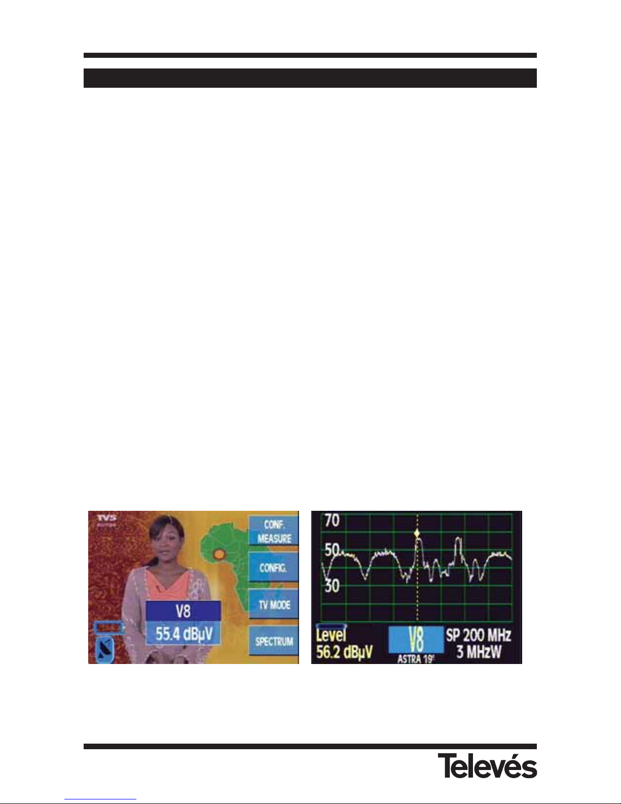
Another important characteristic is that the menu functions are displayed on the 5” coloured
TFT screen. Thanks to the OSD function, we can see the images of the tuned channel (or the
spectrum), the menu functions and other information windows onscreen, as can be seen in the
following figures:
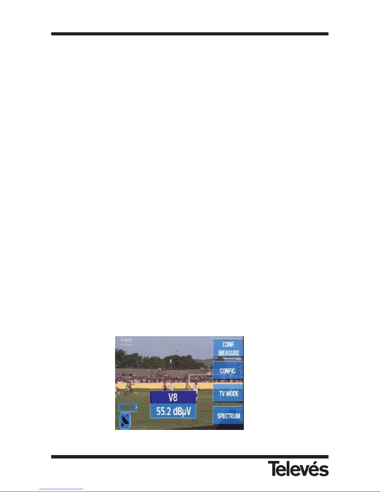
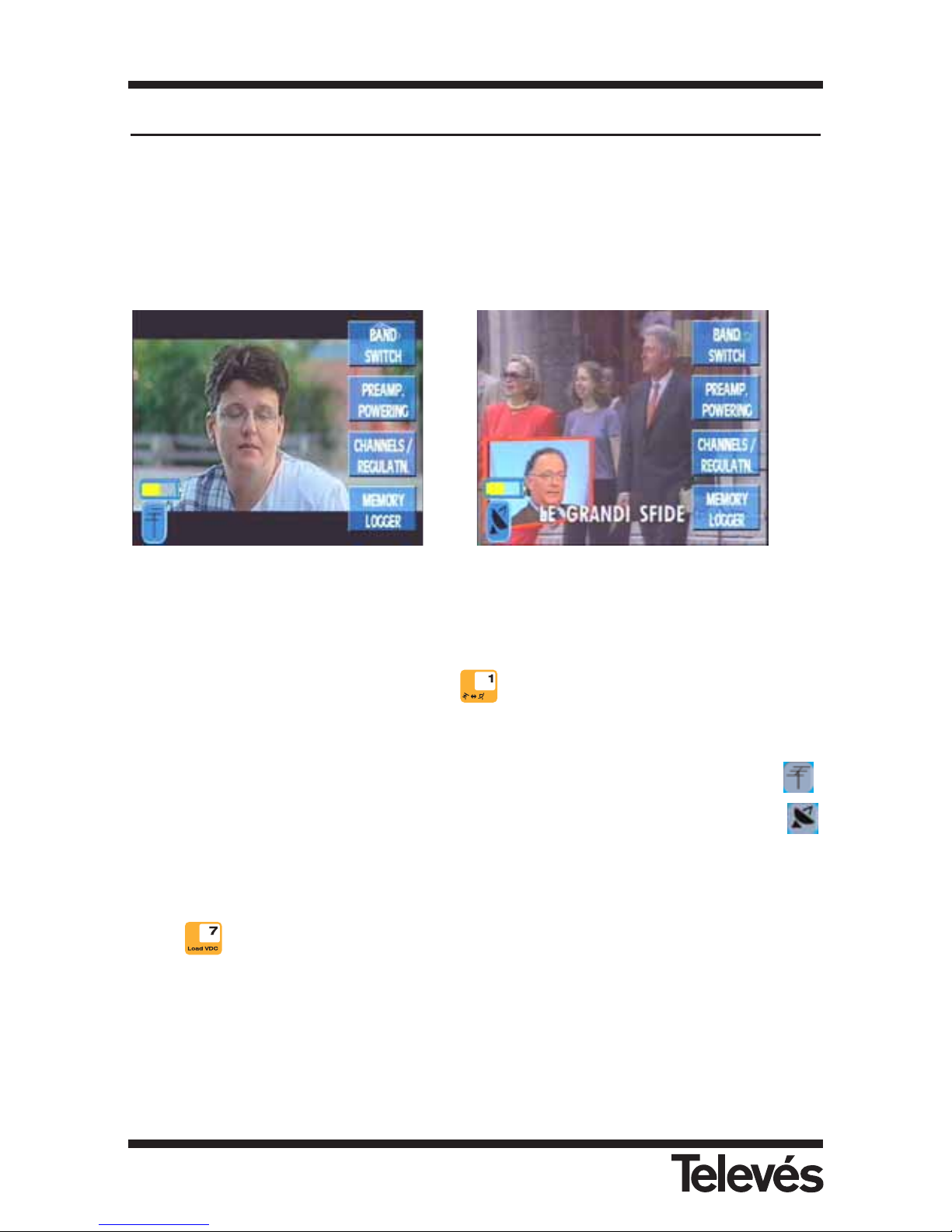
Figure 2.- TV mode or spectrum
To the right of the screen, you can see the buttons that are used to access the function or
submenu that is being indicated at that moment on the screen.
Multimetter FSM 500 Ref. 5903
10
Page 11
2.1.- SPECIFICATIONS
Next, you can see a list of the main specifications of the FSM 500.
Monitor:
Screen TFT 5" colour
Standard Multistandard: PAL (B, G, D, K, I), SECAM (B, G, D, K, L)
Synchronism burst Onscreen presentation via the OSD function
Synchronism 50 Hz
Video signal
External video input: SCART (on, off and auto)
Sensibility: 1Vpp (75 ohm) positive video
Video output: SCART (composite video)
Sound
Input SCART
Outputs SCART and built-in loudspeaker
Demodulation AM, FM and NICAM (OPTION 1)
De-emphasis 50µs/75µs
Subcarrier Variable from 4 to 9 MHz with a 10 KHz resolution both for
terrestrial as well as for satellite signals.
Terrestrial: according to the selected standard:
Satellite: 7.02 and 7.20 MHz, regardless of the standard
Mechanical specifications:
Anti-shock protective holsters
Weight: 5.5 Kgs (without bag).
Size: 280 x 130 x 310 (protective holsters includes)
External units and batteries:
Powering of external units: Via the RF connector
Powering of the
preamplifiers and LNB: Voltage (12/17/24 V) and 22 KHz tone (on and off)
Batteries: 1 battery Ni-MH 12V and 6 Ah.
Automatic shut down: Programmable after a period of inactivity from between 1 and 59
min. (15 min by default)
Battery status: An LED, an onscreen icon and a buzzing noise indicating a low
battery.
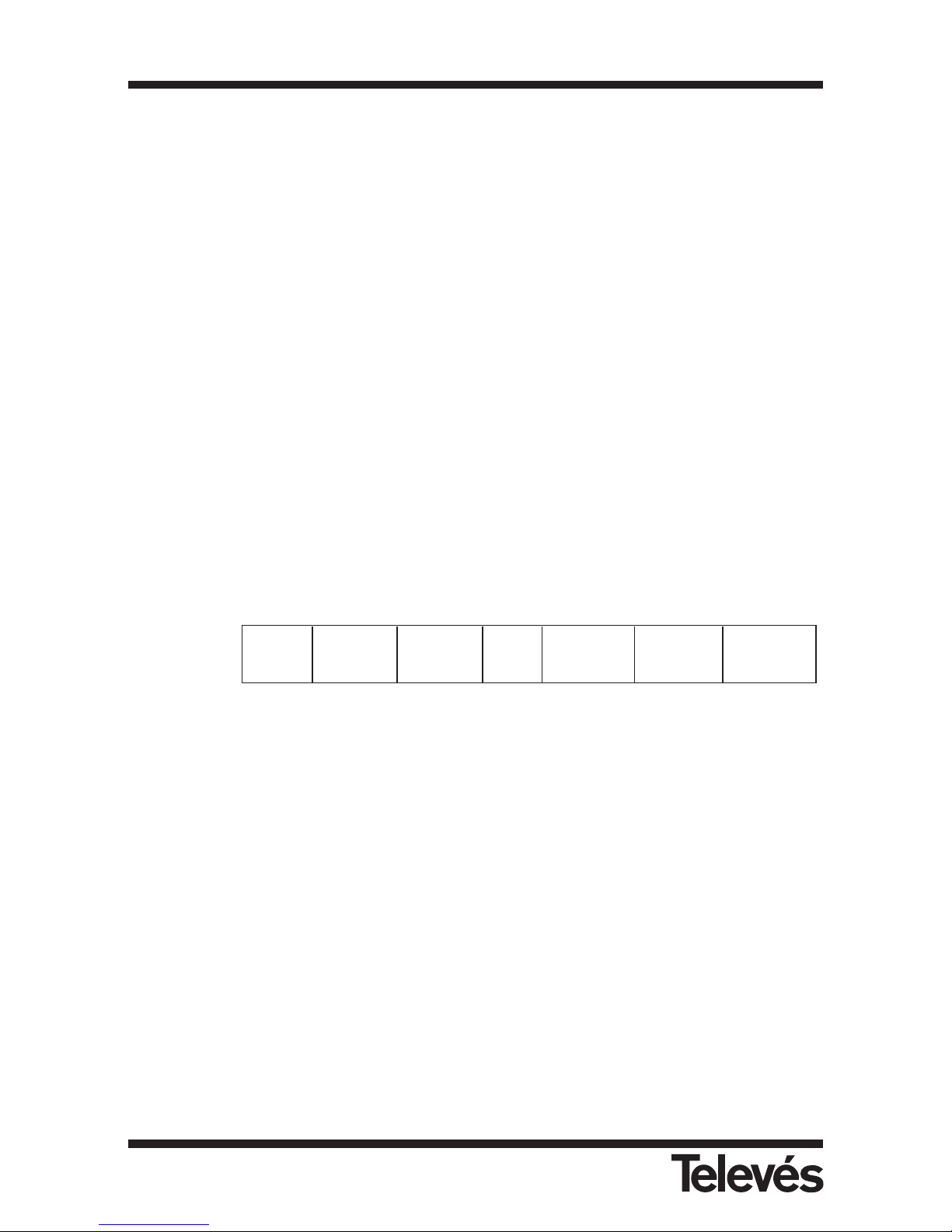
Standard PAL B/G PAL D/K Pal I SECAM B/G SECAM L SECAM D/K
Subcarrier 5.50 & 5.74 6.50 & 6.74 6.00 5.50 & 5.74 6.50 & 5.85 6.50 & 5.85
Multimetter FSM 500 Ref. 5903
11
Page 12

External powering
connection: Via a DC adapter provided with the FSM.
External powering: 12 - 14,8V
Maximum consumption: 35W
Batteries recharged using provided adapter for car lighter
Measurements:
Measurement units: dBµV
Numerical indication onscreen using the OSD function
Frequency range: Terrestrial band: 47-860 MHz
Satellite band: 950-2150 MHz
Return band: 5-47 MHz
GSM band: 860-950 MHz
Frequency resolution: 50 KHz terrestrial and 100 KHz satellite
Resolution level: 0,1 dB
Typical precision: ± 1 dB terrestrial and ± 2 dB satellite
Reading and compensation: Automatic
Dynamic range: Greater than 50 dB
Analogue: Level (numerical indication, bar and audio signal), C/N, V/A
representation of the synchronism burst
Digital: Channel power, C/N, BER, MPEG, MER (OPTION 1), QAM
constellation (OPTION 1)
Level measurement:
Measurement margin:
Terrestrial bands and FM: 15 dBµV to 130 dBµV
Satellite band: 20 dBµV to 120 dBµV
Measurement bandwidth: 250 KHz (terrestrial band) and 3 MHz (satellite band)
Spectrum representation:
Resolution filters: 100 KHz, 250 KHz, 1 MHz and 3 MHz automatically and
manually selectable
Horizontal span: Terrestrial band: selectable (8, 16, 32, 48, 96, 192, 496 MHz) and Full
Span
Satellite band: selectable (25, 50, 100, 200, 512 MHz) and Full
Span
Reference level: Terrestrial band: selectable from 60 and 130 in steps of 10
Satellite band: selectable from 60 and 120 in steps of 10
Multimetter FSM 500 Ref. 5903
12
Page 13

Attenuator: Automatic
Environmental working conditions:
Height: Up to 2000 m
Temperature margin: From 0 to 40 º C
Maximum relative humidity: 80 % (Up to 31ºC), in a linear decrease until 50% at 40º C.
Accessories included:
1 - CD software (FSM Management)
1 - Cable series RS-232
2 - Adapter “F” female / ”F” female (139053)
2 - Push on adapter “F” male / ”F” female (140130)
1 - Adapter “F” female / ”CEI” male (140540)
1 - Adapter “F” female / ”CEI” female (140541)
1 - Adapter “F” female / ”BNC” female (140592)
1 - DC block “F” (140023)
1 - Adapter DC 12V external
1 - Car lighter recharger 12V (140093)
1 - Protective case for travelling
Multimetter FSM 500 Ref. 5903
13
Page 14
2.2.- ELEMENT DESCRIPTION
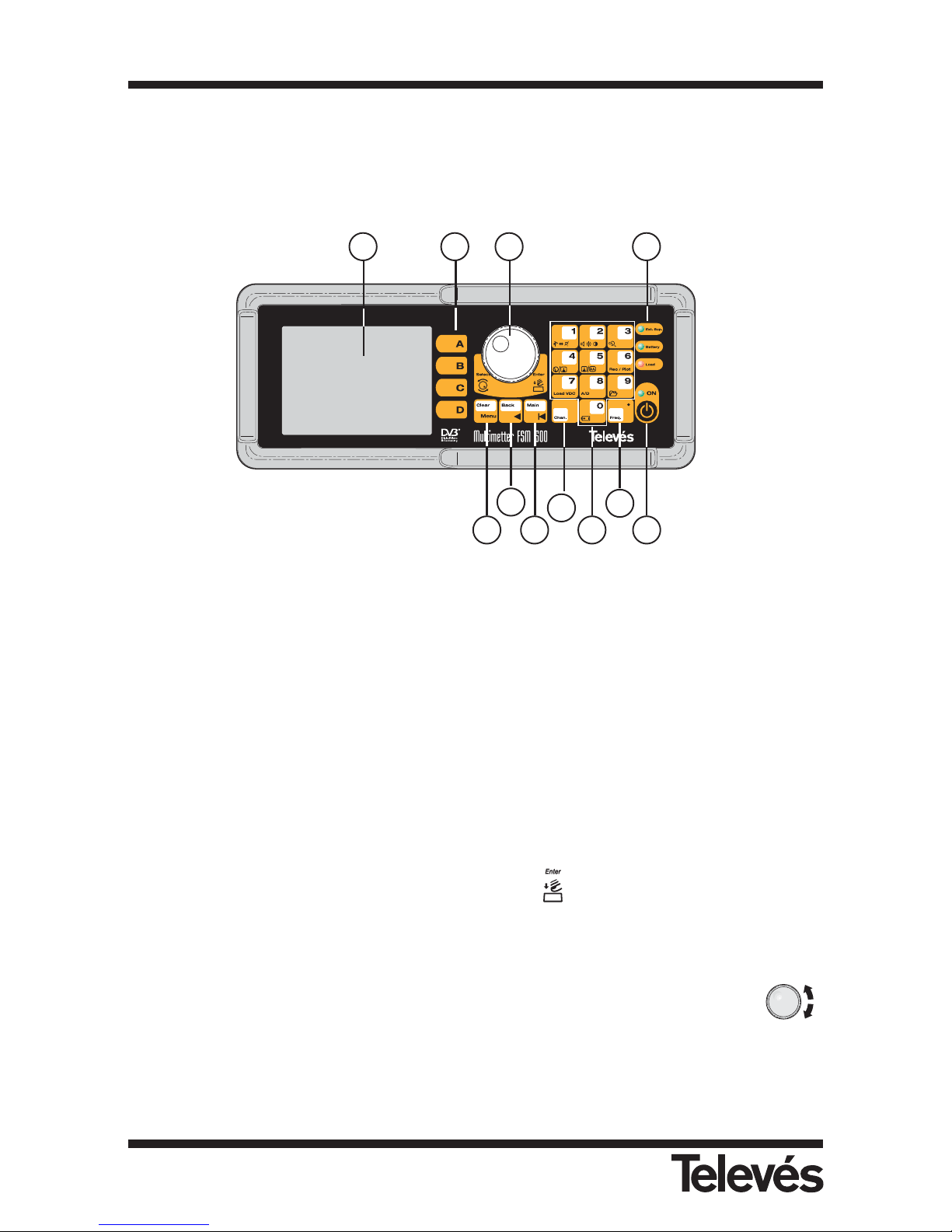
The front panel features the following elements:
Figure 3.- Front panel
(1) Monitor
TFT 5" colour screen
(2) Short cut buttons
Each of these buttons correspond to one of the menu functions that can be seen onscreen
at that moment.
(3) Rotating knob
Depending on where we are on the menu, there are two different functions. For example,
if there is a parameter selection window open, it will allow us to change from one option
to another and to select an option by pressing it . También podrá ser utilizado para
cambiar de canal (modo canal), o sintonizar otra frecuencia (modo frecuencia).
It can also be used to change channels (channel mode) o to tune another frequency
(frequency mode).
In the following sections, when the meter’s functions are explained in detail, the
symbol will be used to indicate the parameters that are selected using the rotating knob.
21 3 11
4
5
8
9
1076
Multimetter FSM 500 Ref. 5903
14
Page 15
(4) Clear/Menu
This makes the menu buttons appear and disappear from onscreen. It is also used to close the
windows that appear in the middle of the screen (measurement windows, parameter selection
windows, etc).
(5) Back
This button has two functions: if the user is entering some data using the number pad
(frequency or password), then this button is used to erase the last digit entered, however
in all other cases this button is used to return to the previous menu.
(6) Main
By pressing this button, the user returns to the main menu.
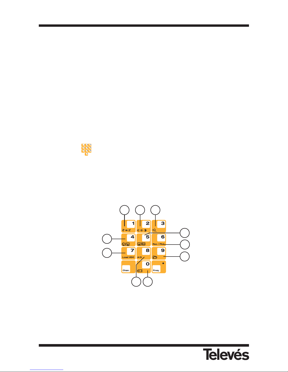
(7) Number pad and short cut buttons
The number pad allows us to enter the frequency that we want to tune. In the following
sections, the symbol will be used to indicate the parameters that can be configured
using the number pad.
Some of the buttons on the number pad are also short cut buttons to the most commonly
used functions.
The following sections explain all of these functions in detail. The functions with a short cut
button will have a picture of this button beside them.
Figura 4.- Teclado principal
(8) Chan
Selects the channel tuning mode. If there is a measurement window open, the tuned
channel will be displayed in it. If there is no window open, the previous measurement
window will be automatically opened.
20 21
28
23
26
22
24
25
29
27
Multimetter FSM 500 Ref. 5903
15
Page 16

(9) Freq
Selects the frequency tuning mode. If there is a measurement window open and the
equipment was previously in the channel tuning mode, when you press the Freq button,
the information regarding the tuned channel disappears and the video carrier frequency of
that channel appears in its place. Once the equipment is in frequency tuning mode, if
we press this button again, the tuned frequency is erased and we can enter the
frequency that we wish to tune using the number pad. To enter the point which
separates the decimal part of the value, we should press this button again. To confirm the
frequency that we have just entered in the number pad, we should press the rotating knob
.
(10) ON
Starting-up button. To switch the equipment off, press this button for more that 2 seconds.
(11) Status LED´s
Ext. Supply: this indicates if the equipment is being powered externally.
Battery: this indicates if the batteries are being charged, and if this is the case, the battery
level. While the batteries are being charged, the LED will flash.
Load: this indicates if the equipment is powering external elements. This is the only LED
that is red so that it clearly warns the installer of this situation.
ON: this indicates if the equipment is switched on.
(20) Switching bands (Button1)
It immediately switches the frequency band from terrestrial to satellite and vice versa, both
in TV mode and in spectrum mode.
(21) Access to the monitor parameters (Button 2)
This lets the user control the brightness, contrast, saturation and volume. Each time this
button is pressed, the following parameter is selected.
(22) Channel search (Button 3)
This automatically tunes the next channel with a carrier level that is higher than the level
selected by the user (see section 3.3.3.3.- Channel search).
(23) Show / hide the previous measurement window (Button 4)
If there is a window of an analogue measurement open (V/A or C/N), when this button is
pressed, it will close. And if we press it again, it will appear again, even if we are in another
place in the menu. However, the level measurement is somewhat different. If the
abbreviated level measurement window is open (this only displays information on the
tuned channel or frequency and the measured signal level) and we press this button, the
extended window will appear, which displays all the data of the abbreviated window as
well as information on the standards, the audio carrier frequency etc.
Multimetter FSM 500 Ref. 5903
16
Page 17

(24) Switching analyser / TV viewing modes (Button 5)
This lets you change from the TV mode to the analyser mode and vice versa.
(25) Printing measurements (Button 8)
This automatically prints the measurement on an RS-232 printer.
In Analyser mode, you can access the graph menu and save the graph that you are
viewing (OPTION 1).
(26) External powering (Button 7)
This opens the window that displays information on the powering of external units. These
units are powered via an input F connector.
(27) Selecting analogue / digital measurements (Button 8)
This lets you change from the analogue to the digital measurements and vice versa. The
menus are automatically located on the parts that correspond to the analogue or digital
measurements. When the analogue measurements are selected, the level measurement
window is opened, and when the digital measurements are selected, the power
measurement window is opened and the picture onscreen disappears.
(28) Battery charging (Button 0)
By pressing this button for more than 3 seconds, the battery will begin recharging,
whatever the battery level may be, as long as the meter is connected to the mains. The
user can abort the recharging process by pressing this button again for more than 3
seconds.
Note: If the temperature is too high, the charging process will not begin, and if this process
is already underway, when the temperature reaches a certain level, the process will
stop and will start again once the temperature has returned to an appropriate level
(29) Memories Logger (Button 9)
This lets you directly access the Memory lists, the Macro Measurements, Data Logs and
Graphics (OPTION 1).
Multimetter FSM 500 Ref. 5903
17
Page 18
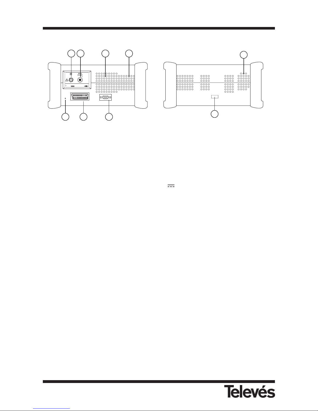
Side view:
Figure 5.- The connectors on the side panels
(30) RF input
Input connector for the signal with an impedance of 75 ohm.
(31) Powering
Input for the external powering of 12 - 14,8 V
(32) Serial port
Connection to the PC in order to use the FSM Management programme or for the
upgrading of the meter’s software.
Connection printer RS 232.
(33) SCART
(34) Reset button
When the user presses this button, it restarts the equipment. When you do this, the
equipment retrieves the same configuration that it had when it was switched off propertly
for the last time.
To reset the equipment, the user should use an object that is not sharp or particularly
pointed, and gently press the button.
(35) Loudspeaker
(36) Ventilator
(37) Switch for configuration of batteries
(38) Ventilator
38
37
SCART
RS-232
RESET
V.max. 24 V
I.max. 400 mA
12 ... 14,8 V
30 31
33 3234
35 36
Multimetter FSM 500 Ref. 5903
18
Page 19
3.- HOW TO USE THE PRODUCT
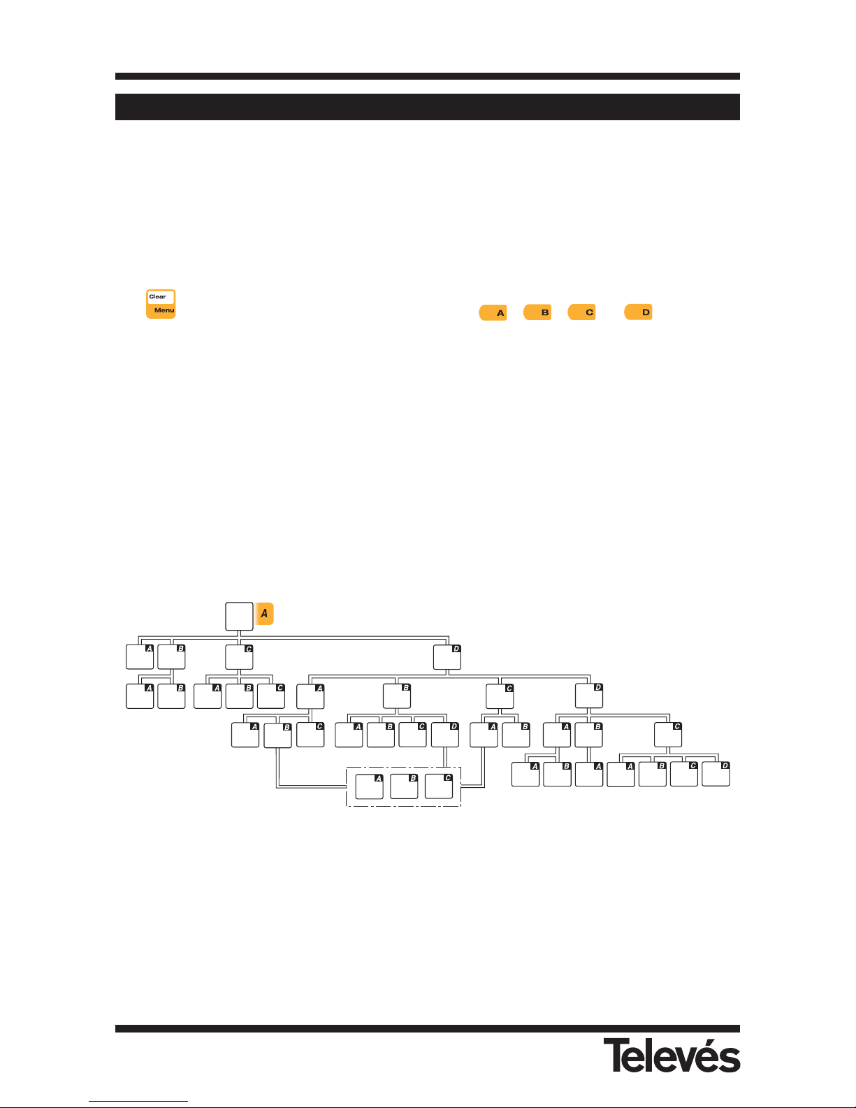
3.1.- THE MENU
As explained previously, the different functions of the equipment have been placed in
hierarchical order, so that they are very user-friendly.
The menu texts appear onscreen, superimposed over the picture, which can be the
demodulated picture from the tuned TV channel (TV mode) or the spectrum (analyser mode). If
in TV mode, the background of the text windows is slightly transparent so that it is still possible
to see the picture. If we are looking at the spectrum, the menu texts are invisible by default, until
the button is pressed or until one of the buttons , , or are pressed
so that in this way, you can still see the spectrum properly.
If you do not have OPTION 1, the unavailable functions will appear in grey on the meter.
If the equipment is in TV mode, when the user wants to change a parameter or see a
measurement, once the corresponding function has been selected, a window opens onscreen
with a transparent background.
If however, the equipment is in analyser mode, the measurements appear on the lower part of
the screen, so that the user can see the measurement and the spectrum at the same time.
Here you can see a diagram which shows the equipment’s functions in their hierarchical order:
Config.
Measure
Preamp.
Powering
Band
Switch
Channels
Regulatn
Regulatn.
Select Plan
LNB
DiSEqC
Memories
Macro
Measure
DataLogs
Memory
Logger
Video
Invertion
Save
Delete
Edit
New
Macro
Edit
Macro
Edit
Name
Erase
Confirm
Cancel
Select
All
Confirm
Cancel
Select
All
Erase
Log
Edit
Logs
Graphics
Save
Graphic
Edit Name
Delete
Graphic
GLOG
options
Edit
Name
Edit Graphic
Name
Select
Graphic
Multimetter FSM 500 Ref. 5903
19
Page 20
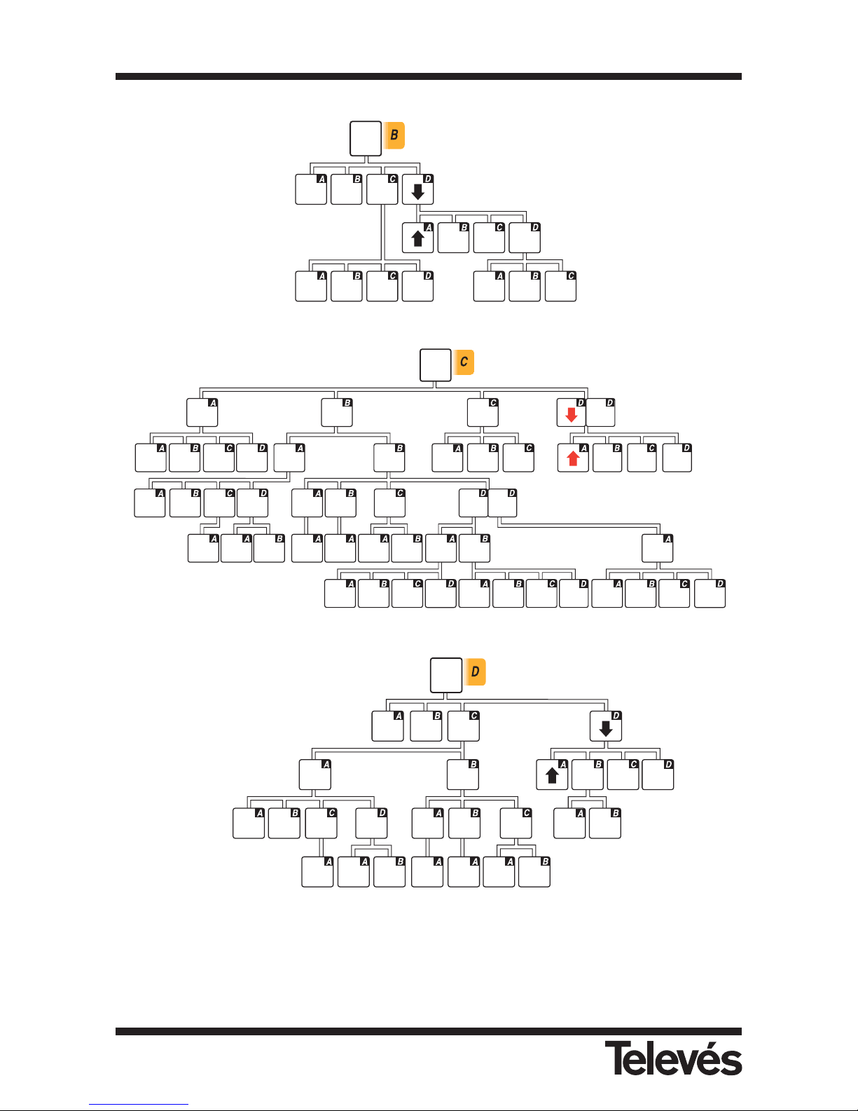
The functions with blue text are the measurements for the satellite band.
The functions with red text are the measurements for the terrestrial band.
Marks
RBW
Spectrum
Ref. Level
Span
Measure
Analogue
Digital
Reference
C/N
V/A
Level
Reference
C/N
Channel
Power
Ref. Frec.
Channel BW
Ref. Frec.
Channel BW
Auto C/N
Channel BW
Channel BW
Auto C/N
Channel BW
Sing./Doub.
Mark
Mark
Change
Hold
On/Off
TV
Mode
View Mode
Measure
(types)
Bar
Sync.
Measure
Window
Analogue
Digital
Channel BW Channel BW
Channel BW
Ref. Frec.
Channel BW
Reference
C/N
V/A
Level
Reference
C/N
Channel
Power
Teletext
Auto C/N
Ref. Frec.
Auto C/N
COFDM
QAM QPSK
Param.
Error
Packet
BER
Param.
Param.
Error
Packet
BER
Search
Level
Next Prev.
Channel
Search
Channel BW
MPEG
BER
MPEG
MPEG
NICAM
Sel. Audio
Carrier
FM
Sel. Audio
Carrier
BER
Measure
BER
Measure
Constella.
Volume
Config.
Language
Auto
Dsconnect
Monitor
Paramtres
Brigh.
Contrast
Color
Update
Battery
Change
Info Equipo
Clock
Scart
Informa.
Battery
Regenerat.
Multimetter FSM 500 Ref. 5903
20
Page 21
3.2.- TUNING MODES
The FSM 500 has 2 tuning modes: by channel or by frequency. To select one or the other, use
the Chan. (channel tuning) and Freq. (frequency tuning).
If using the channel tuning option, the measurements taken will be done on the video carrier of
that channel. For example, if the selected plan is the CCIR, and the tuned channel is S01, the
video carrier frequency is 105.25 MHz. Therefore, when the level is measured, the video carrier
frequency level will be measured. If, for example, we want to measure the C/N, the equipment
will automatically look for the video carrier frequency and carry out the measurement in this
frequency. The same will happen with the V/A ratio measurement.
When a measurement window is open, and we press the Chan. button, we will go to the
channel tuning mode, and we will see the tuned channel onscreen. If we turn the knob, the next
channel will be automatically tuned and the new measurement will appear in the window.
On the other hand, if the frequency tuning mode has been selected, the measurements will be
carried out in the frequency that is indicated. For example, if the C/N measurement is selected,
the carrier level will be measured in the frequency selected by the user, which may not coincide
with the video carrier of a channel. When a measurement window is open, and when we press
the Freq. button we will go to the frequency tuning mode and the text with information about
the frequency will be highlighted (dark background). In this way, we will be able to vary the
frequency using the rotating knob (variations of 50 KHz in the terrestrial band and 100 KHz in
the satellite band). If we press the Freq. button again, the information about the frequency will
disappear and we will be able to enter the frequency using the number pad. To confirm the
frequency press the rotating knob.
If the frequency tuning mode is selected and we press the Chan. button, we will access the
channel tuning mode, and the window that is open at that moment will display the name of the
channel that that frequency belongs to (according to the channel plan that is selected).
If the channel tuning mode is selected and we press the Freq. button, we will access the
frequency tuning mode and the frequency that appears is the video carrier frequency of the
channel that was tuned.
3.3.- FUNCTIONS
This sections explains all of the meter’s functions in detail.
The main menu has the following options:
Figure 6.- Main menu option
3.3.1
3.3.2
3.3.3
3.3.4
Multimetter FSM 500 Ref. 5903
21
Page 22
3.3.1.- Measurement configuration
By using the functions in this menu you can set the parameters that affect the measurements that
you are going to take.
All of the windows that are opened with the different functions of the “Measurement
Configuration” menu can be closed by pressing the Clear button.
Within this option we have the following submenu:
Terrestrial band Satellite band
Figure 7.- Submenu options
3.3.1.1.- Band switching (short cut button )
This lets you switch bands from terrestrial to satellite and vice versa. When the band switching
occurs, the icon at the bottom left-hand corner of the screen also changes at the same time. If
the terrestrial band is selected, the icon that appears is an antenna for terrestrial signals ,
and if the satellite band is selected, the icon the appears is an antenna for satellite signals
3.3.1.2.- Preamplifiers (terrestrial band) / LNB and Preamplifiers (satellite band). Short cut
button :
It is acceded to the menu for the configuration the power to preamplifiers and LNB.
When turn ON the measurer, the option that appears selected will be always OFF.
This menu varies depending on which band is selected (terrestrial or satellite).
In the terrestrial band, a window will appear in which the installer can select the power and the
tone of the preamplifiers:
3.3.1.1
3.3.1.2
3.3.1.3
3.3.1.4
3.3.1.1
3.3.1.2
3.3.1.3
3.3.1.4
Multimetter FSM 500 Ref. 5903
22
Page 23
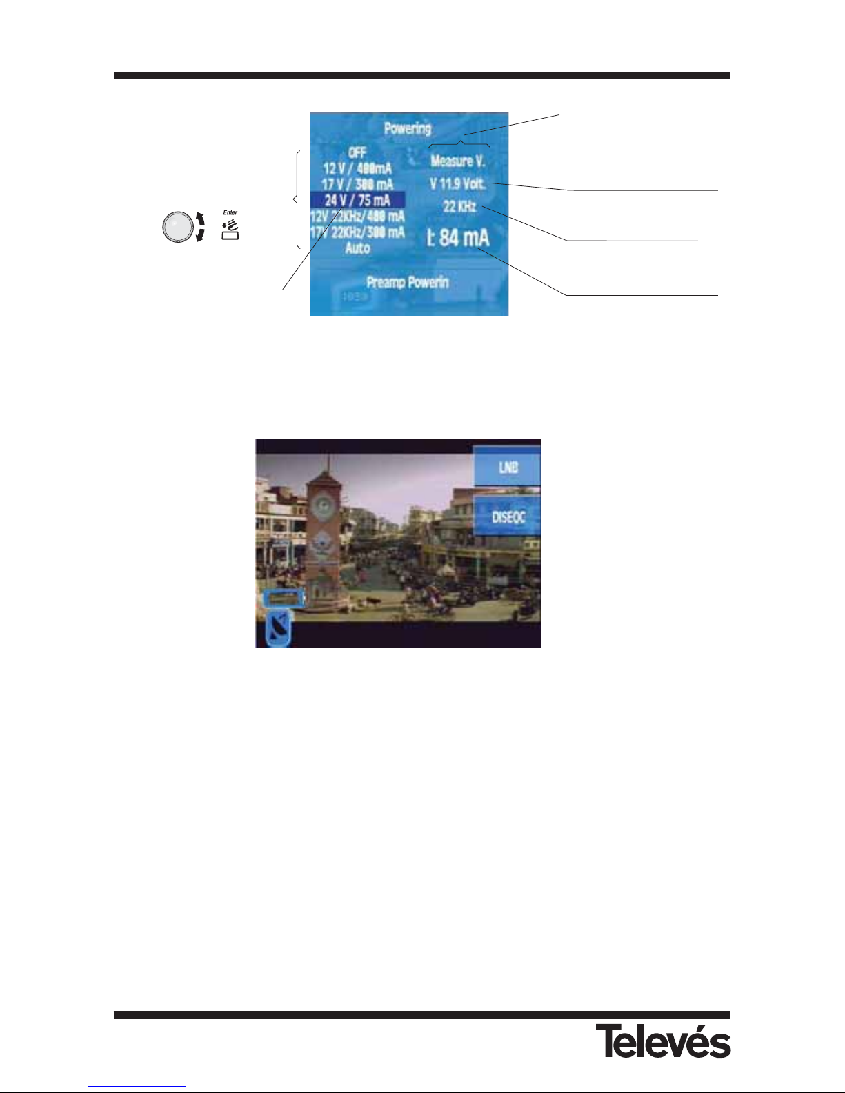
Figure 8.- Preamplifier powering
If the satellite band is selected, when the preamplifier powering option is pressed, the following
submenu will appear:
Figure 9.- Options available in the preamplifier powering submenu
It is worth noting that when a voltage is activated for the powering of an external device, the
red led will light up (Load). If this led flashes, it is indicating that there is an error.
Also, the programming of the voltage depends on the band that is selected at the time, so that
if 24V is selected in the terrestrial band, this does not mean that this voltage will pass to the
satellite band.
3.3.1.2.1.- LNB (only satellite band):
When this function is selected, a window which is very similar to the previous one opens. The
user can use this function to select the powering and tone of the LNB.
3.3.1.2.1
3.3.1.2.2
Indicates if the 22KHz
tone is activated
Options.
These are selected by
using the rotating knob and
are activated when this
knob is pressed
Option to select
Indicates the power that
is being used
Indicates the power that is
being supplied
Current status of the
equipment
Multimetter FSM 500 Ref. 5903
23
Page 24
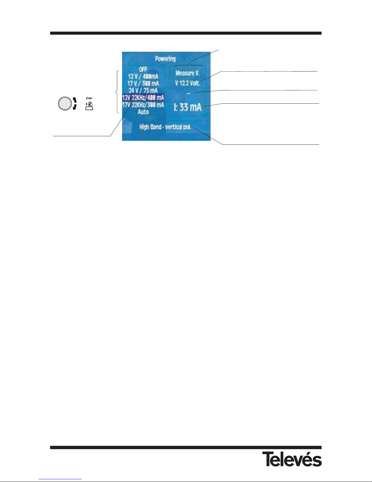
Figure 10.- LNB powering
If in the satelllite band, the band (high or low) and the polarity (vertical or horizontal) that
correspond to the selected powering and tone appear on the lower part of the windows
12V / 400mA ==> low band, vertical polarity
17V / 300mA ==> low band, horizontal polarity
24V / 75mA ==> preamplifier powering
12V 22KHz / 400mA ==> high band, vertical polarity
17V 22KHz /300mA ==> high band, horizontal polarity
Auto ==> this is only useful in the satellite band. It sets the
appropriate power and tone automatically, according
to the selected channel table, (using a universal LNB)
to select the band (high or low) and the polarity
(vertical or horizontal) to tune the selected channel.
The equipment continuously monitors the current in the F connector, and warns the user of any
error by means of a message window that appears on top of any other window that may be
open. The possible problems which may arise related to the powering of the external units are
as follows:
· The equipment detects a current in the coaxial cable. In this case, the message that appears
as a warning is "Vext". This situation should be avoided.
· When the equipment detects a shortcircuit, it emits an audio signal and the message that
appears as a warning in this case is “Shortcircuit".
· In the same way, the equipment warns the user when the consumption is greater than the
maximum amount permitted. The message that appears is "Exceeded limit". In the last two
cases, the power is cut-off and it automatically tries again approximately every 3 seconds.
Indicates if the 22KHz tone is
activated (in this case, it is not)
Options.
These are selected by
using the rotating knob
and are activated when
this knob is pressed
Option to select and
limit the current
Indicates the power that is being used
Indicates the power that is being
supplied to the preamplifiers
Current status of the equipment
This indicates the band and the
polarity that are selected using the
marked option (in this case 12V 22
KHz/400 mA), and not the one that is
currently activated.
Multimetter FSM 500 Ref. 5903
24
Page 25
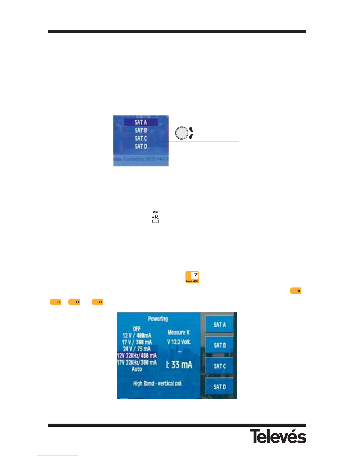
3.3.1.2.2. DiSEqC (satellite band only):
The Diseqc protocol lets you work with multiswitches that have up to 16 inputs. To do so, when
the meter is in the satellite band, you must enable, in the powering menu, the current and tone
that corresponds to the desired polarity and satellite band. As well as the chosen band and
polarity, it is necessary to specify the satellite that we are going to receive the signal from (the
multiswitches organise the different polarities in groups of four, and identify each group using
the names SAT A, SAT B, ...). To do so, the user must enter into the DiSEqC section in the
"Measurement configuration" menu and also in the "LNB and preamplifiers" menu. The
following window will appear:
Figure 11.- Selecting the satellite in the multiswitch
The user must choose the appropriate satellite (a multiswitch with 8+1 inputs will only have
satellite A and satellite B at its disposal).
Once this has been selected, press
. The equipment begins to send the command that
informs the multiswitch about the chosen satellite, as well as the band and the polarity (which
have been previously selected in LoadVDC).
When one of the DiSEqC inputs is chosen, if the powering of external units is off, an error
message will appear.
When in satellite mode, using the short cut button it is possible to access simultaneously
the LNB and DISEQC menus. We can choose the desired satellite using the buttons ,
, or .
Figura 12.- Fast selection of the satellite
Possible options
Multimetter FSM 500 Ref. 5903
25
Page 26
3.3.1.3.- Channels and Standards
3.3.1.3.1.- Standard
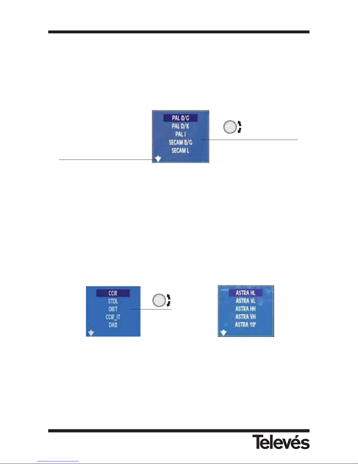
This allows you to select the colour standard. The standards that are available are as follows:
PAL B/G, PAL D/K, PAL I, SECAM B/G, SECAM L and SECAM D/K.
The window that appears when this function is selected is as follows:
Figure 13.- Standard selection
3.3.1.3.2.- Select Plan
This selects the channel plan that the user wants to use. The options that will be available with
this function will depend on the band that is selected:
Terrestrial band: CCIR, STDL, OIRT, CCIR-IT, DAB, SIM.7637
Satellite band: ASTRA 19 HL, ASTRA 19 VL, ASTRA 19 HH, ASTRA 19 VH, ASTRA 19,
HOTBIRD HL, HOTBIRD VL, HOTBIRD HH, HOTBIRD VH, HOTBIRD,
HISPASAT HL, HISPASAT VL, HISPASAT HH, HISPASAT VH, HISPASAT,
SIM.4008, ASTRA 28, EUROBIRD, NILESAT, ARABSAT, TURKSAT,
EURASISAT, AMAZONAS, SIRIUS 5, THOR 1W.
Channel plans in the terrestrial band Channel plans in the satellite band
Figure 14.- Channel plans
Note: The ASTRA 19, HOTBIRD, HISPASAT, plans include all the channels in both bands and
both polarities, ordered according to their frequency. If the LNB needs to be powered, it
is advisable to select the Auto option in the power supply menu for the preamplifiers and
the LNB.
Selectable options
using the rotating
knob
This indicates that there are
more options. These will
appear as we turn the knob.
Multimetter FSM 500 Ref. 5903
26
Page 27
3.3.1.3.3.- Video invertion
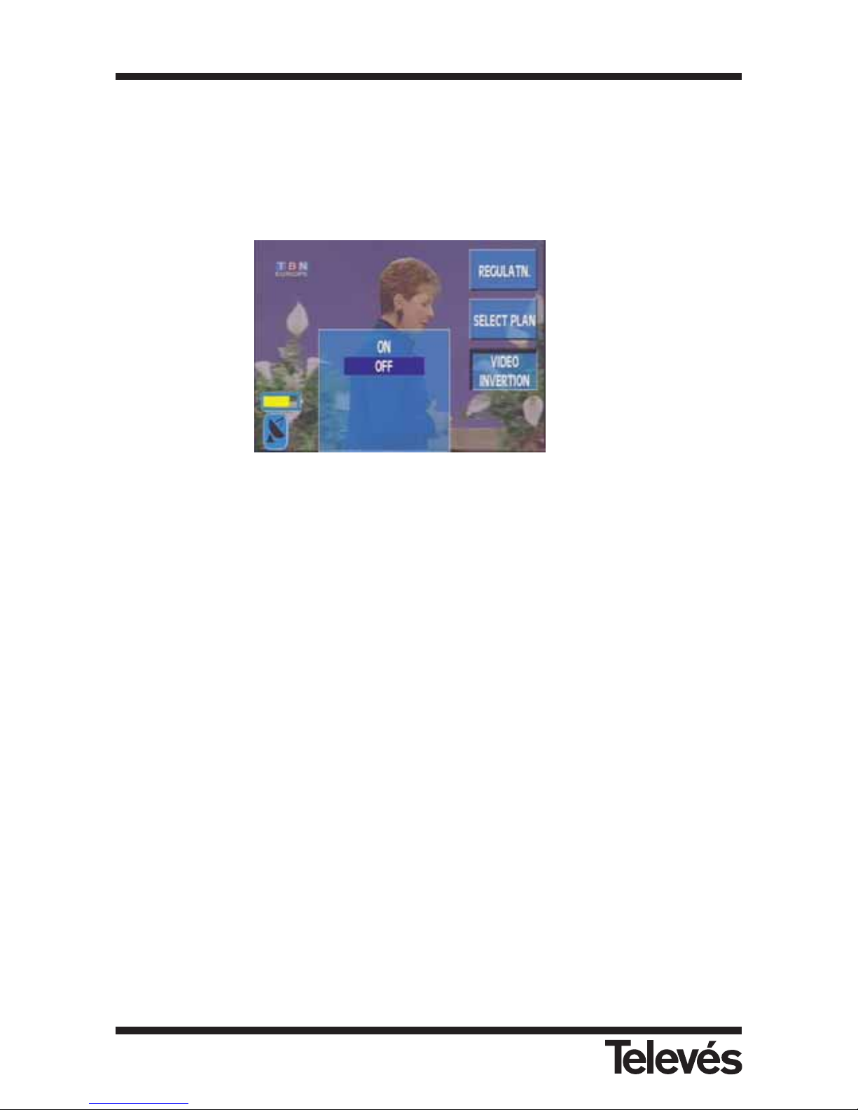
This function lets you select if the video signal that comes from a satellite band is inverted (ON)
or not (OFF). By default, this option is OFF.
It is useful when watching the video of satellites from the C band.
Figure 15.- Video polarity selection
3.3.1.3.1
3.3.1.3.2
3.3.1.3.3
Multimetter FSM 500 Ref. 5903
27
Page 28
3.3.1.4.- Memory Logger.
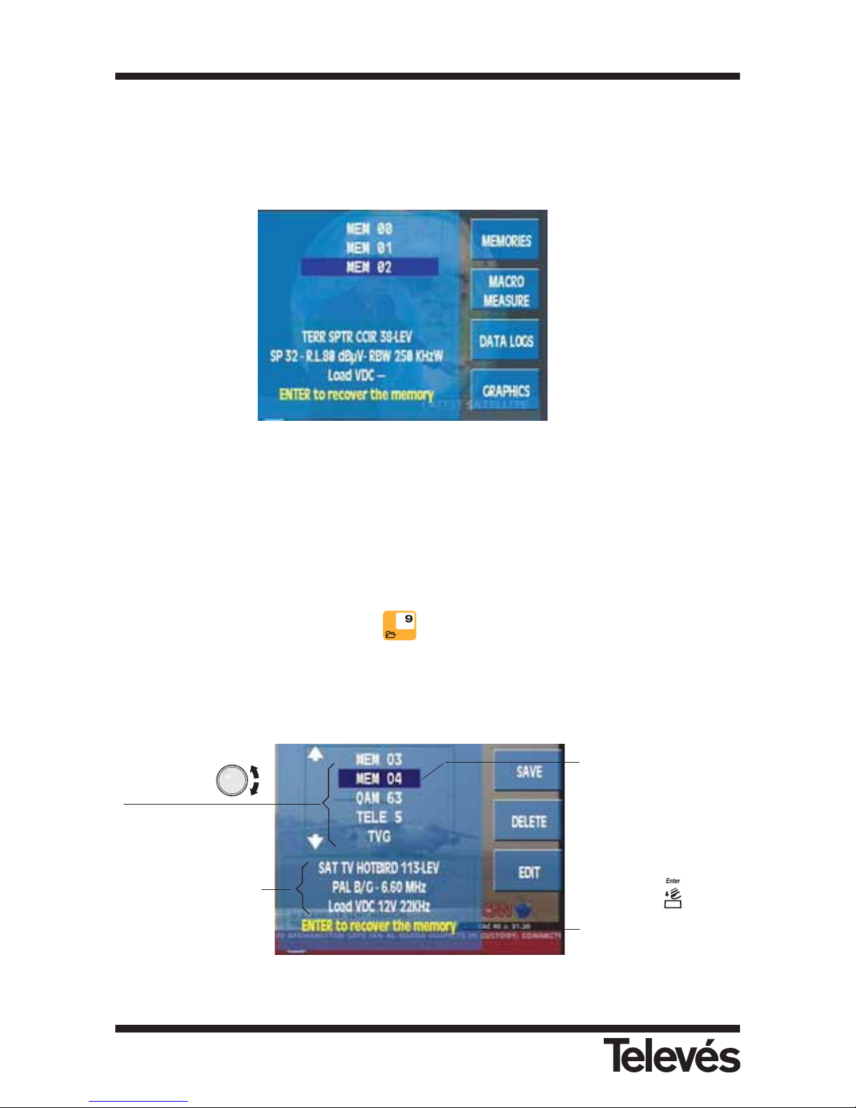
This section describes how to access a series of functions that let you turn the majority of
processes that you carry out with the meter into automatic operations.
On screen you will see a window with a list of the meter memories. If no memories have been
recorded, the window will be empty.
Figure 16.- List of available memories
Using this menu, it is also possible to access the graph functions, however this will only happen
when the meter is in analyser mode. If you do not dispose of the graph option, the menu key
will appear with a shadow.
3.3.1.4.1.- Memories. Short cut button :
The FSM 500 lets you save up to 100 different configurations (memories) for your equipment,
which you will be able to retrieve very simply.
The measurer is able to store any state in which is as mode, norm, measurement type, etc.
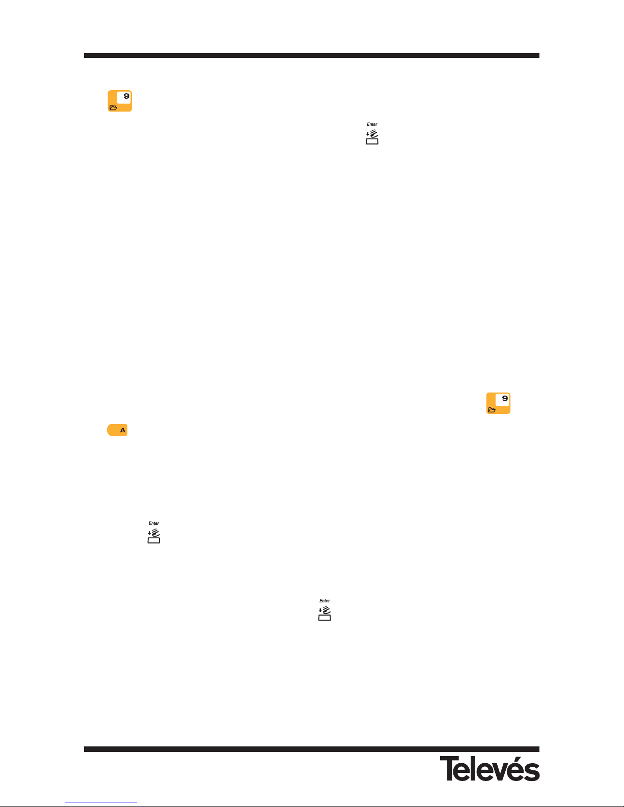
Figura 17.- List of available memories
Information about the
selected memory:
satellite band, TV
mode, channel plan
HOTBIRD, channel
113, level
measurement, norm:
PAL B/G, audio
carrier, powered
preamp.
List of stored
memories
Selected memory
From the main memory
menu, it is possible to
select any of the
memories on the list.
By pressing button,
the equipment retrieves
the configuration
corresponding to this
memory.
3.3.1.4.1
3.3.1.4.2
3.3.1.4.3
3.3.1.4.4
Multimetter FSM 500 Ref. 5903
28
Page 29
To configure the equipment according to the stored parameters in a specific menu, simply press
the button (or go to the CONF. MEASURE => MEMORIES LOGGER => MEMORIES
menu), select the desired memory from the list and press .
If there isn't any memory in the meter, the message "NO MEMORIES" will appear onscreen.
By default, the meter has two memories called INTEG0 (C/N Auto, Analogue TV mode, 7,5 Mhz,
6.0 Mhz Bandwidth) INTEG2 (C/N Auto, Analogue TV mode, 22.65 Mhz, 1.5 Mhz Bandwidth).
These two memories should be used together with the return channel simulator, ref. 7637, in
position 0 and 2. The equipment also includes the channels plan of this simulator.
These memories enable the analysis of the Return Channel, and have been especially designed
for Televés Integra installations. Both configurations will be treated similarly to the memories
defined by the user, and because of this, they can be edited or eliminated.
3.3.1.4.1.1.- Save
To save a specific memory, place the meter in the desired configuration and press . Use
the button to select the MEMORIES function. The menu from the previous figure will
appear. Now press the SAVE button. The list of memories will be located at the end of this list
and the name of the following free memory will flash on and off.
By default, the name of the memory that appears is always Mem followed by two digits
ordered according to their values, but the user can name each memory as desired.
There are four options:
1.- Press to accept the name that appears by default.
2.- If we want to change the digits only, we simply need to press the desired numbers on
the number pad.
3.- If we want to write over a memory in the list, we need to use the rotating knob to reach
the memory. Once here, we should press .
4.- If we want to change the name of the memory, press the EDIT button.
Multimetter FSM 500 Ref. 5903
29
Page 30
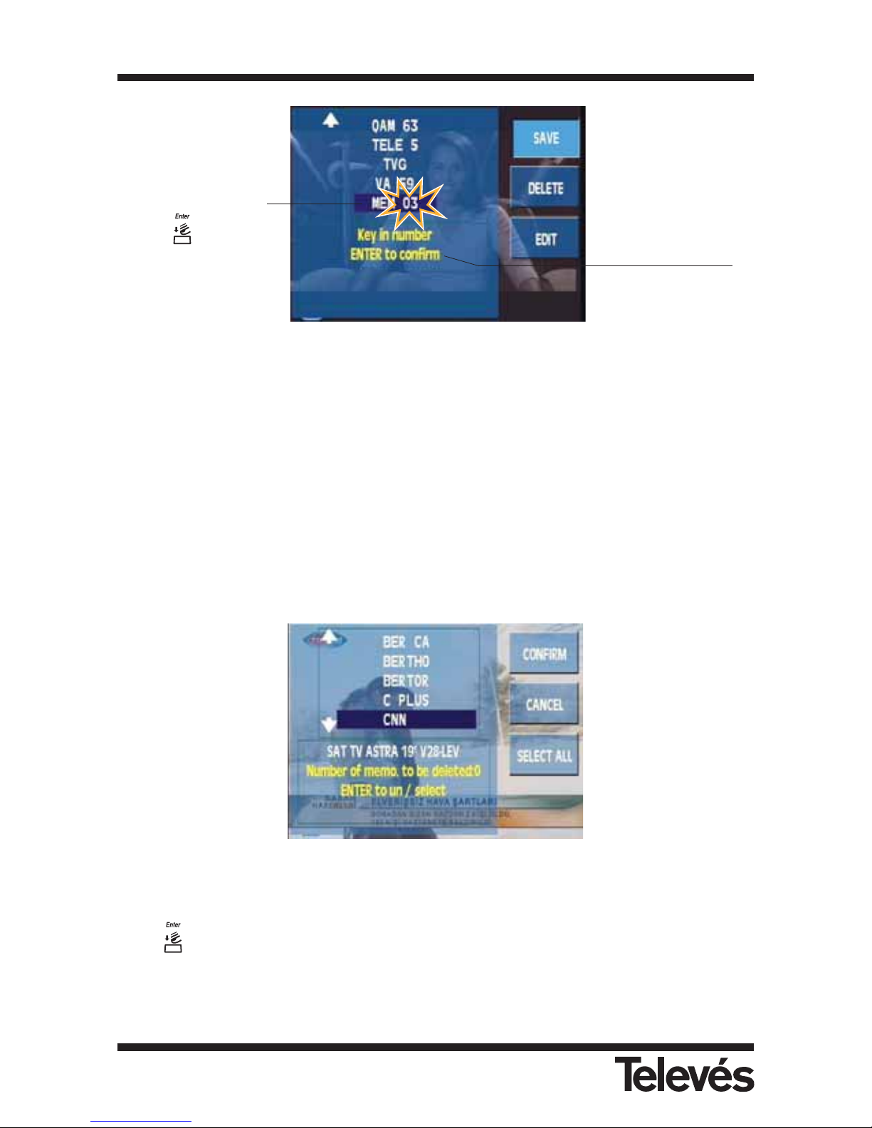
Figura 18.- Saving a memory
When the user confirms that s/he wants to save the memory, the message "MEMORY SAVED"
will appear onscreen.
The maximum number of memories that the meter can store is 100. If the memory capacity is
full, the message "MEMORY FULL" will appear onscreen.
3.3.1.4.1.2.- Delete
When you want to delete a specific memory, press the DELETE button. Next a new window
appears where you can see the list of the available memories.
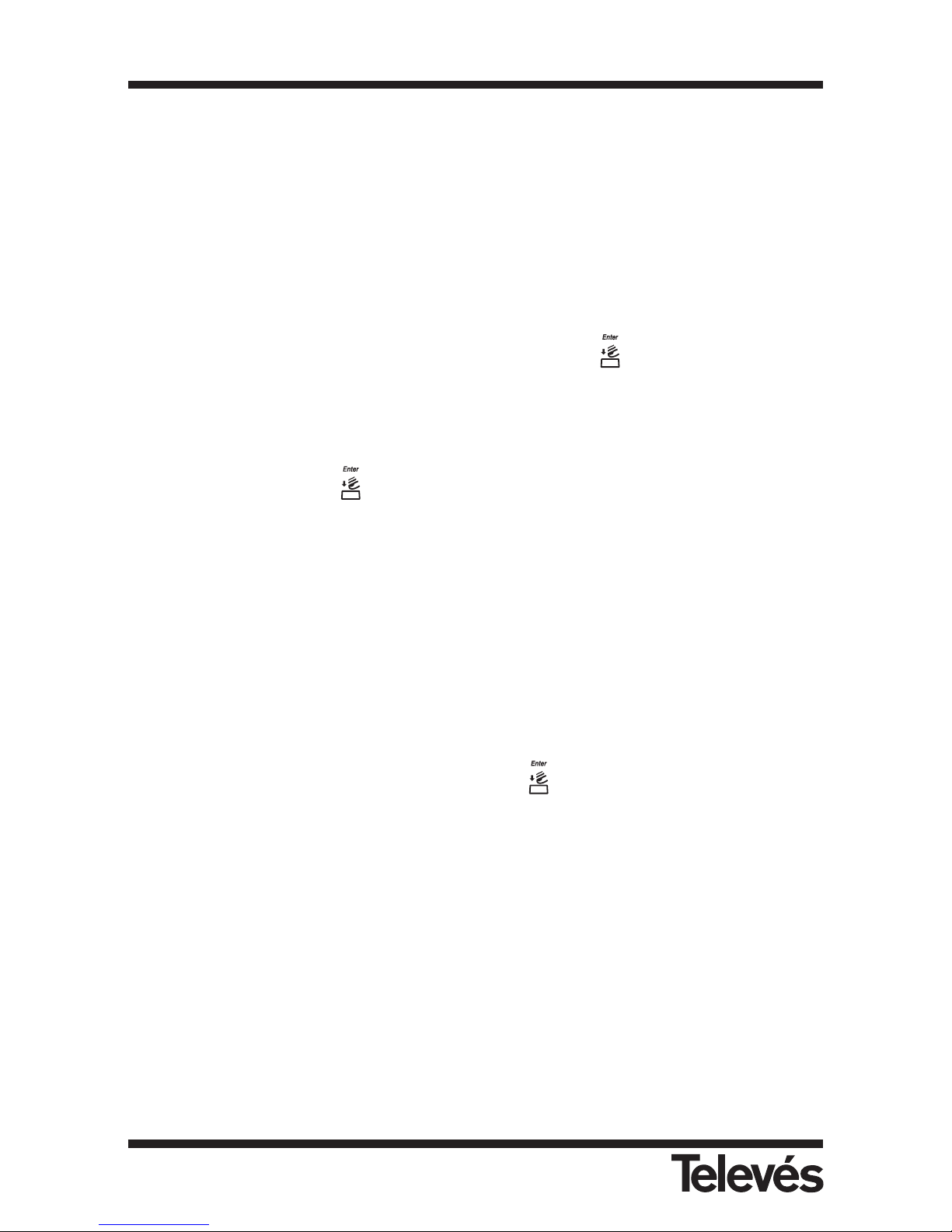
Figura 19.- Deleting memories
Use the rotating knob to move through the list. When you find the memory you want to erase,
press
,
and this memory will be highlighted.
If you want to select all the memories in the meter, you can use the SELECT ALL option, so
that all the memories are highlighted.
When you have finished selecting, press CONFIRM.
First free memory.
Flashing digits with the
lower disposable
number.
Press to save.
On the lower part of
the window, the
instructions that the
user must follow to
save the memory
appear.
Multimetter FSM 500 Ref. 5903
30
Page 31
When the user confirms that s/he wants to erase a memory, the message "MEMORY ERASED"
will appear onscreen.
3.3.1.4.1.3.- How to Edit a Name
This function enables the user to modify the name of any memory, whether it has been saved
or whether it is a new memory that the user wishes to save.
If it is a memory that is already on the list, press the EDIT button and then, using the rotating
knob, select the memory name that you want to modify. Press to accept.
The first letter of the name will start flashing thereby indicating that this is the letter that is to be
edited. By turing the rotating knob, the rest of the letters in the alphabet including the numbers
from 0 to 9 will appear. The "_" indicates a blank space, in other words, once the memory name
has been saved, it will be sustitued by a blank space. Once the letter that you want appears in
the position desired, press and begin the process again with the following letter in the
name.
If you want to return to the previous letter, press the Back button.
The name of each memory should have between 1 and 6 characters. Once the 6 characters
have been edited, the process has finished. If the proposed name does not have 6 characters,
it will be necessary to fill in the remaining spaces with blanks ("_").
If re-naming a memory that already exists, and if the new name has less characters than the old
name, the characters that you wish to erase should be replaced with "_" (in other words, blank
spaces).
If you are editing a memory that you are saving, press EDIT when the name proposed by the
equipment is flashing. From now on, the process will be as described in the previous paragraph.
If you are trying to save a memory with the name of another memory in the list, the equipment
will warn you. You can confirm the action by pressing (in this case, the old memory will be
erased) or you can cancel the action. To do so, simply rotate the knob (the name will disappear
and the process will begin again).
It is not possible to save a memory with a name consisting of blank spaces only. In this case,
the meter will display a message indicating that the name is incorrect.
When the user confirms the modification of the name of a memory, the message "MEMORY
EDITED" will appear onscreen.
Multimetter FSM 500 Ref. 5903
31
Page 32
3.3.1.4.2.- Macromeasurements
A MACROMEASUREMENT is a group of a specific number of memories (different
measurements), that the meter will be able to execute automatically and add the results to a
specific measurement LOG. You can configure up to 100 different MACRO
MEASUREMENTS! (automatic measurements with different memories).
The meter can carry out measurements from a list of memories whenever necessary, and then let
the user view the results on the meter, or let the user download these measurements to the PC.
Conceptually, the meter can create the register per LOG and at the same time, in groups of outlets.
A DATA LOG is the list of results (measurements) that are obtained when a
MACROMEASUREMENT is executed automatically, once or various times (different outlets in
the same installation). The meter stores, at the same time up to 100 different DATA LOGS !.
The equipment proposes a default name to identify the LOG. This name consists of a name
(LOG) and the macromeasurement that was used.
Each DATA LOG (depending on the number of DATA LOGS that we have) can store the results
of hundreds of different outlets, each one with tens of measurements. For example:
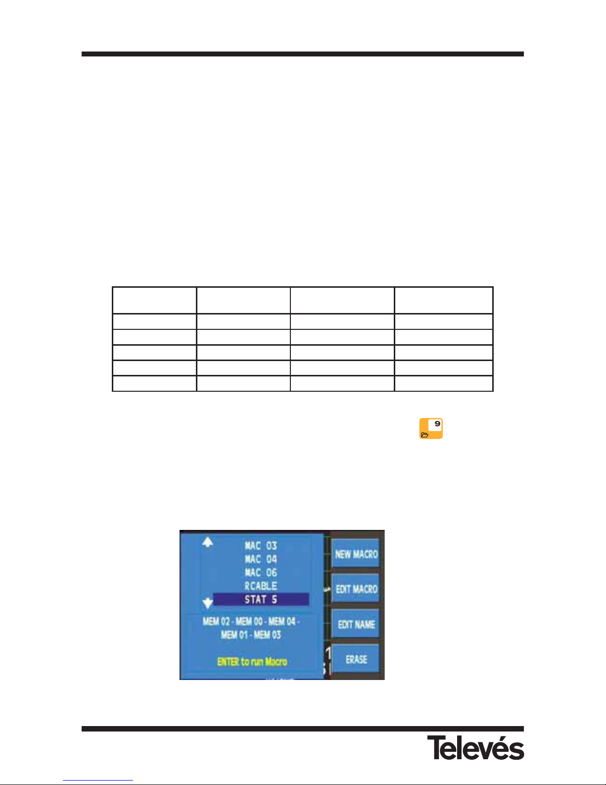
To execute a Macromeasurement quickly press the short cut button , then the option
MACROMEASUREMENTS. The window will display a list of available Macromeasurements. If
no Macromeasurement has been created (see section 3.3.1.4.2.1.- New Macro) the window will
be empty. Use the rotating knob to highlight the one we want to execute. The content of each
Macromeasurement is displayed at the bottom of the window.
If there is no macromeasurement saved in the meter, the message "NO MACROS" will appear
onscreen.
Figure 20.- Macromeasurements
3.3.1.4.2.1
3.3.1.4.2.2
3.3.1.4.2.3
3.3.1.4.2.4
No. DATA LOGS
No. of outlets/
DATA LOG
No. of Memories
(measures) / outlet
No. of MEASURES
1 440 70
30800
2 303 50
30300
3 100 100
30000
5 110 54
29700
10 40 70
28000
Multimetter FSM 500 Ref. 5903
32
Page 33
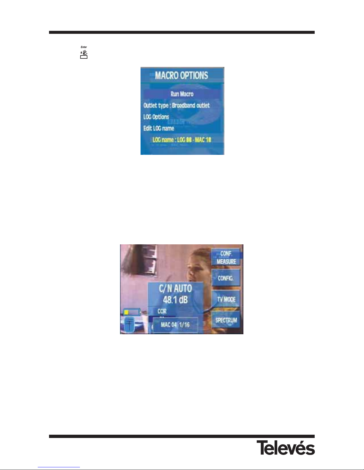
When the is pressed, the MACRO OPTIONS menu is displayed.
Figure 21.- Macro options
Use the rotating knob to choose the different options of this menu:
- Run Macro. Starts the execution of the selected Macromeasurement. If the selected
macromeasurement does not contain any memory, the meter will display the
following message "MACRO EMPTY".
Figure 22.- Execution of a Macro
- Outlet type. There are two choices, by default the Filtered outlet is used. The equipment
establishes an execution order of the Macromeasurement. During the
Macromeasurement and before carrying out the measurements that correspond
to the satellite, the Meter will display a message warning that the connector of
the separating outlet should be changed in order to continue executing the
Macromeasurement.
Multimetter FSM 500 Ref. 5903
33
Page 34
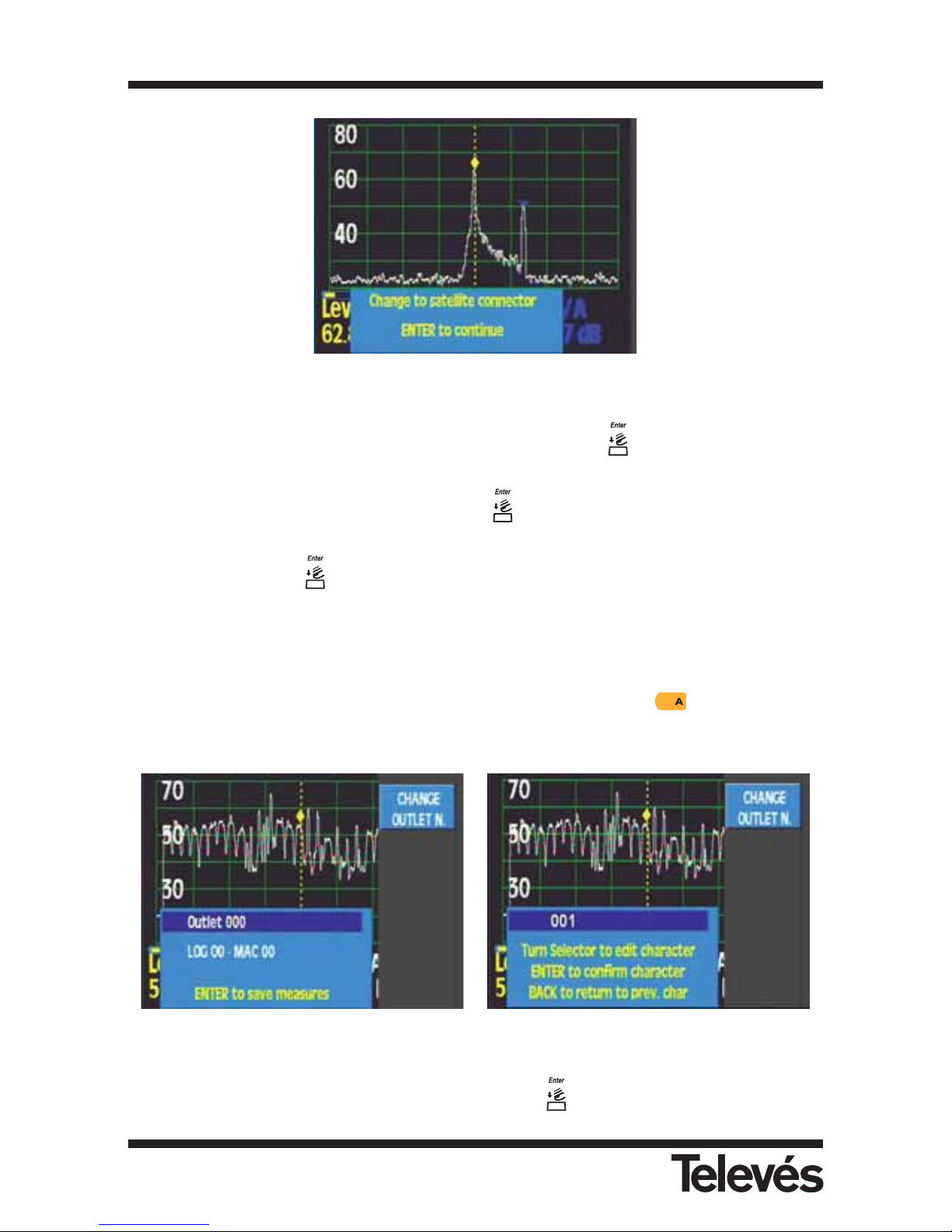
Figure 23.- Change to satellite connector
The other possibility that can be chosen using the button is the Broadband
outlet where the equipment carries out the Macromeasurement in both bands
with no interruptions. If you press a drop down menu will appear where you
can choose an option using the rotating knob and accept your choice by
pressing .
During the executing process of a Macromeasurement a window will appear onscreen with
information about the process. When the process is completed, the meter will make a warning
noise and will propose a number for the outlet that was measured. This number will be the
lowest avaible. The user can edit the name of the outlet by pressing the button (CHANGE
OUTLET N.).
Figure 24.- Editing Outlet name
After naming the outlet, it can be saved by pressing the
button.
Multimetter FSM 500 Ref. 5903
34
Page 35
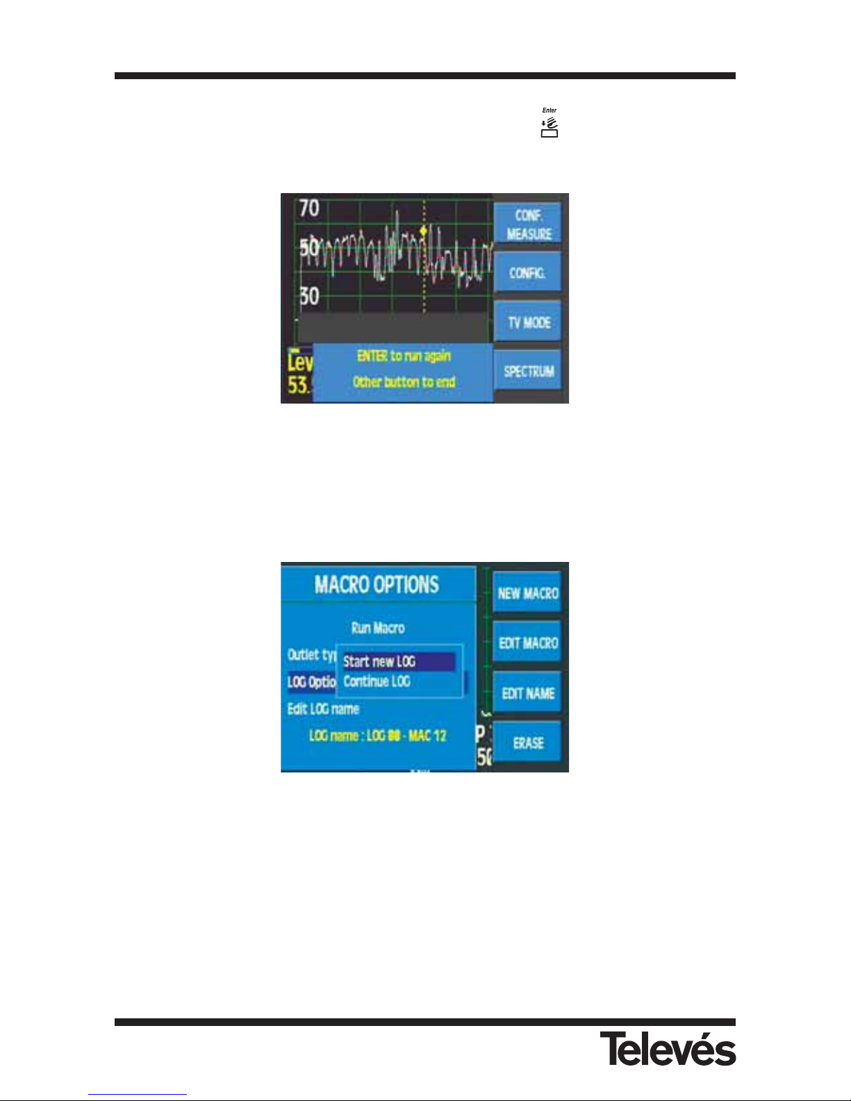
To execute the Macromeasurement again in a new outlet, press again. If you want to
finish the Macromeasurement, press any button.
Figure 25.- Continue or cancel Macromeasurement
- LOG options. This option lets us select the possibility of continuing with a LOG which we had
previously created or of starting with a new one, in this case the equipment will
suggest a name for the new "LOG" register and will also suggest a two-digit
number which will be the lowest available.
Figura 26.- LOG options
- Edit LOG name. This function lets the user modify the name of the new LOG.
Multimetter FSM 500 Ref. 5903
35
Page 36
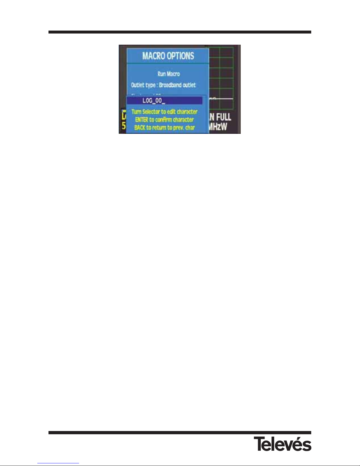
Figure 27.- Editing the LOG name
Note: If we are executing a Macromeasurement, the function "Automatic shut-down"
will be postponed until the end of this process.
Multimetter FSM 500 Ref. 5903
36
Page 37
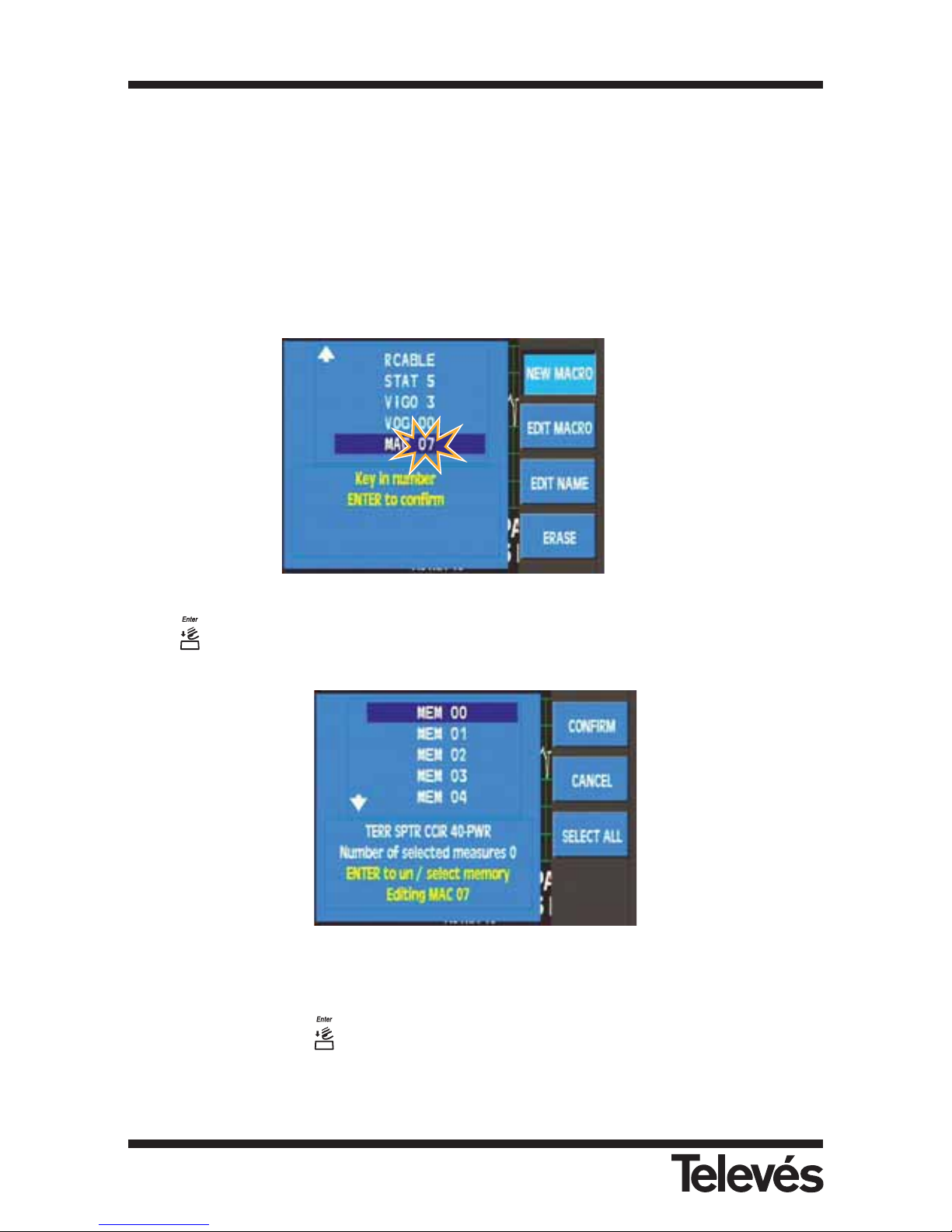
3.3.1.4.2.1.- New Macro
This option lets us create new Macromeasurements using the memories inside the meter.
A window opens and the name of a Macromeasurement appears with the cursor flashing. The
name that the equipment proposes to identify each Macromeasurement is: “MAC” and a twodigit number which will be the lowest number available at that time. Using the function
“3.3.1.4.2.3.- Edit Name” we can name the Macromeasurement as we like, so as to identify it
more easily.
The maximum number of Macromeasurements that can be stored in the meter is 100, if the
user tries to save a new Macromeasurement, the message "MACROS FULL" will appear
onscreen.
Figure 28.- Create new Macromeasurements
Press to confirm, and then a list of the available memories appears.
Figure 29.- Editing a Macro
We can use the rotating knob to move through the list. When we find the memory we are going
to use, we should press and the memory will be highlighted.
If we want to select all the meter’s memories, we can use the SELECT ALL option, so that all
the memories are hightlighted.
3.3.1.4.2.1
3.3.1.4.2.2
3.3.1.4.2.3
3.3.1.4.2.4
Multimetter FSM 500 Ref. 5903
37
Page 38
At the bottom of the window, we will be able to see some important information about each
memory that has been selected and the number of memories that we are putting into the
Macromeasurement.
When we have finished the selection process, we must press CONFIRM and then . The
message "MACRO SAVED" will appear onscreen.
3.3.1.4.2.2.- Edit Macro
This option lets the user change the memories inside a Macromeasurement. It works in the
same way as when creating a new Macromeasurement.
3.3.1.4.2.3.- Edit Name
This option lets you change the name of a Macromeasurement.
Once you have confirmed the change of name the message "NAME CHANGED" will appear
onscreen.
3.3.1.4.2.4.- Erase Macro
We can erase a Macromeasurement when we think it is necessary using this option. It works in
the same way as then erasing a memory.
Once the macro has been erased, the meter will inform you via the message "MACRO
ERASED".
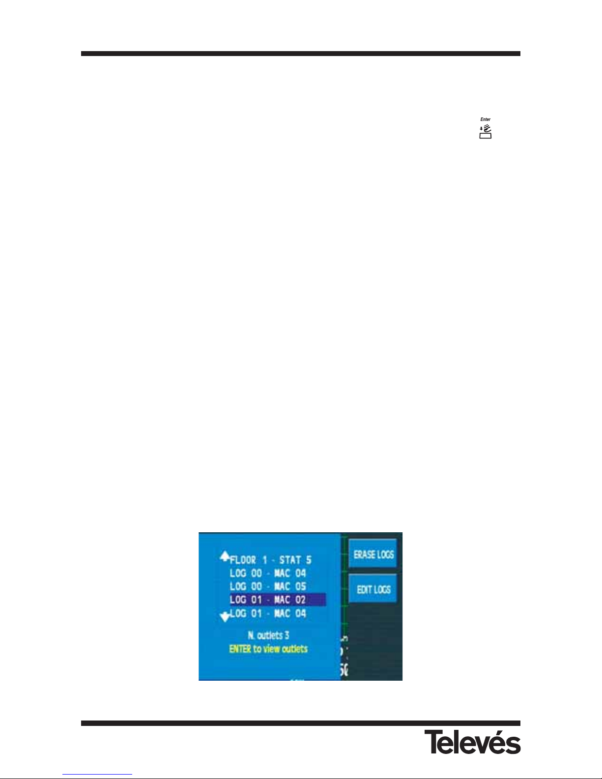
3.3.1.4.3.- View DATA LOGS
This function lets you see the results of the Macromeasurements that you have executed.
The meter will display a window with a list of the DATA LOGS. At the bottom of the window you
will see the content of each one.
Figure 30.- List of DATA LOGS
Multimetter FSM 500 Ref. 5903
38
Page 39
If there aren't any DATALOGS stored in the meter's memory, the message "NO DATALOGS" will
appear onscreen.
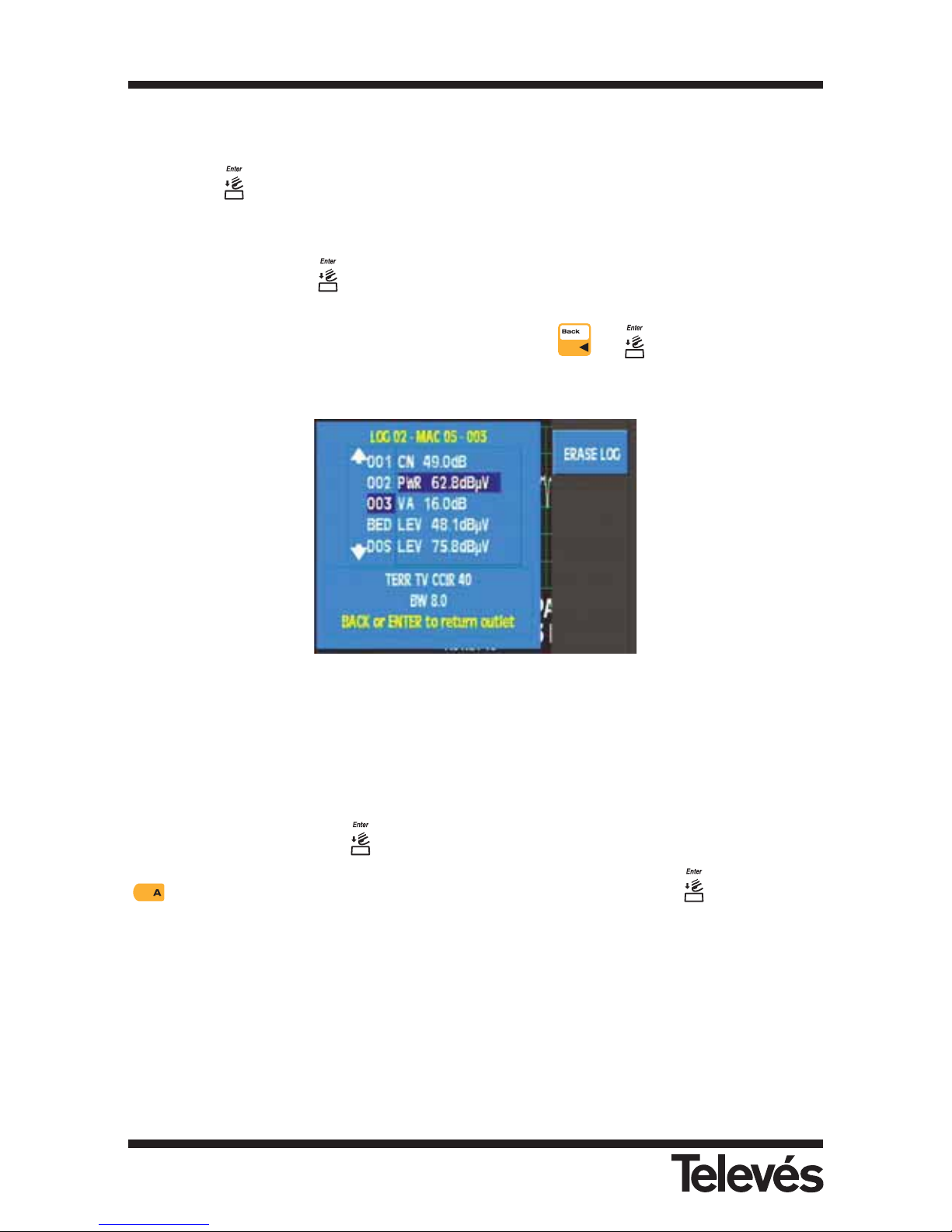
By pressing a table with two columns will appear. On the left there are the outlets that have
been measured and on the right there are the results of each outlet.
By turning the rotating knob, we can move through the different sockets of the LOG (left-hand
column) and by pressing we go to the column with the measurements of the socket that is
highlighted (right-hand column). We can move through the different measurements of the
socket in this column using the rotating knob. By pressing or we return to the socket
column.
Figure 31.- Measurements in each outlet
3.3.1.4.3.1.- Erase LOGS
This option lets you erase the selected LOGS. To do this, use the rotating knob to mark the
LOGS, selecting them using . The marked registers will appear in yellow, then press the
button (CONFIRM) and complete the erasing process by pressing . The message
"DATALOG ERASED" will appear onscreen.
Note: When you erase or edit a memory, it is also being erased or edited in the
Macromeasurements where it appears. Erasing or editing a Macromeasurement
does not affect the LOGs that have been generated with the erased or edited
Macromeasurement.
Multimetter FSM 500 Ref. 5903
39
Page 40
3.3.1.4.3.2.- Edit LOGS
This option lets us change the name of the desired LOG at any time. To do so, use the rotating
knob to select the LOG, confirm your selection by pressing the key. The name of this LOG
will flash on and off and using the rotating knob and button, we can change the characters.
3.3.1.4.4.- Graphs (OPTION 1)
Function dealing with the graphs in the meter. This function will be available when the meter is
in analyser mode as long as the user disposes of OPTION 1. If you try to access this function
in another mode, the message "ONLY SPECTRUM" will appear.
The meter lets you register up to 100 simple graphs or 50 graphs with maximums.
If the maximum function is enabled, both lines will be saved.
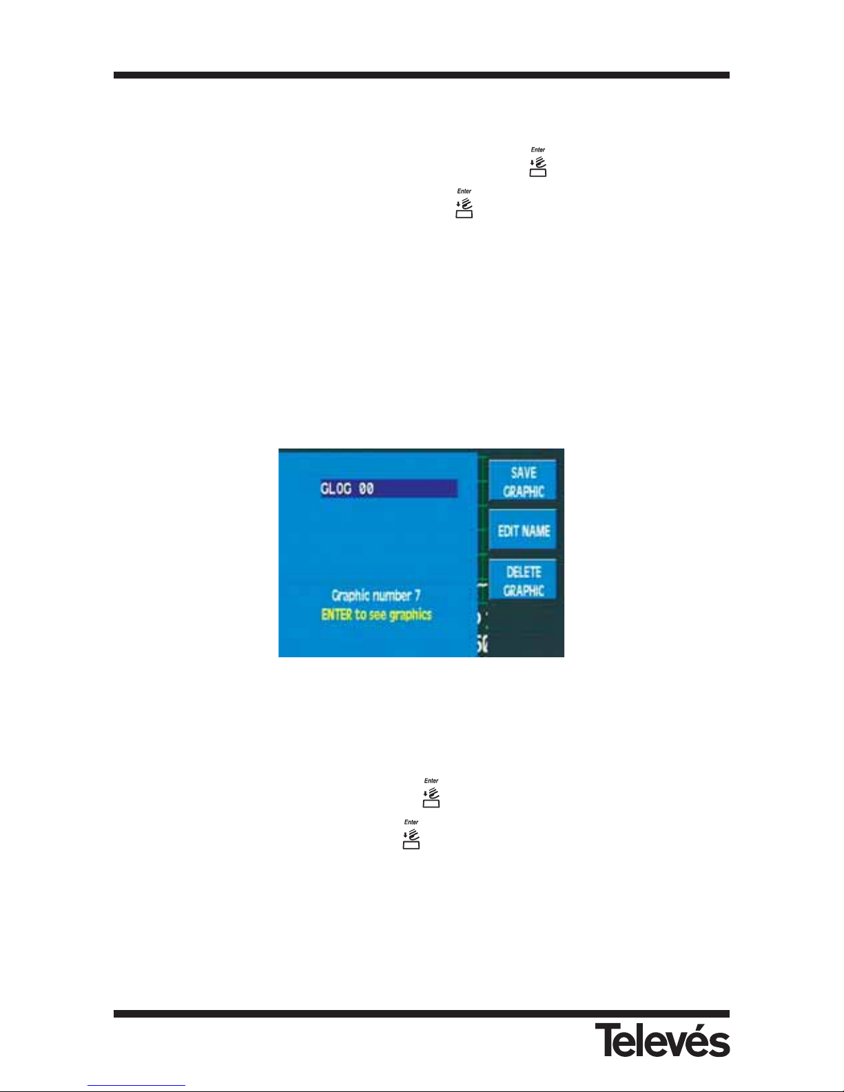
Figura 32.- GLOGs list
In this case of not having any graph saved, the meter will display the onscreen message "NO
GRAPHS".
In order to see the graphs we will use the rotating knob through the GLOGs list and once we
have found the desired one, we should pres and the list of graphs that it contains will
appear. We can select the graph and press to retrieve it.
Multimetter FSM 500 Ref. 5903
40
Page 41
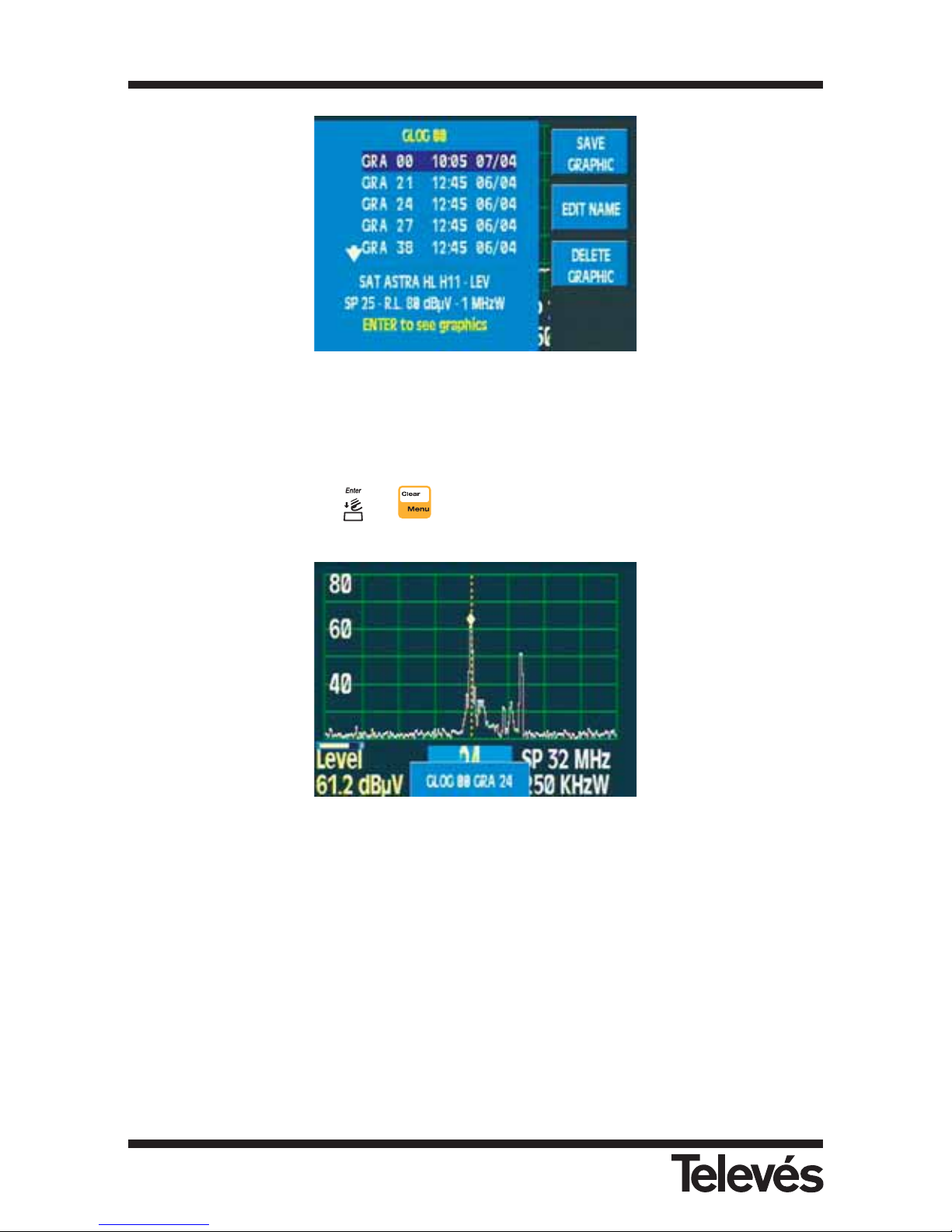
Figura 33.- List of graphs of a GLOG
While we are reviewing the graphs, a flashing message will appear onscreen which displays the
name of the GLOG and the graph. Using the rotating knob, we can scroll through the graphs in
the GLOG.
To exit viewing mode, press or .
Figura 34.- A stored graph
3.3.1.4.4.1.- Save graphs
This option lets you save the graph that is being shown on the meter.
Multimetter FSM 500 Ref. 5903
41
Page 42
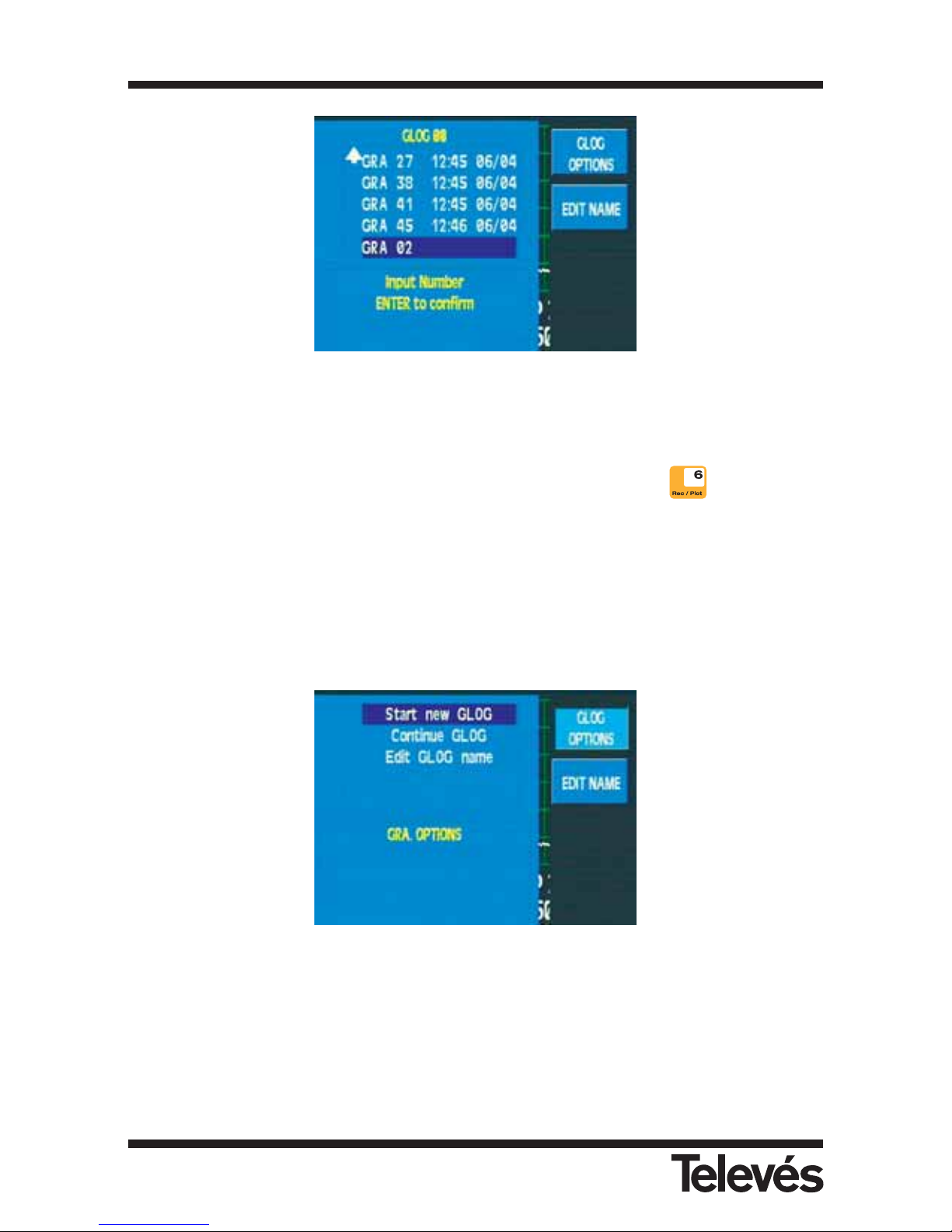
Figura 35.- Save a graph
We can put the graphs together into groups called GLOGS. The name of the first group of
graphs suggested by the meter will be GLOG00.
In Analyser mode, we can easily save a graph using the short cut button .
3.3.1.4.4.1.1.- GLOG options
These functions let the user modify the location of the new graphs in the new GLOGS, in
previously-created GLOGS or modify the name of the current GLOG.
Figura 36.- GLOG options
3.3.1.4.4.1.2.- Edit Name
This option lets the user modify the name of the graph before saving it.
Multimetter FSM 500 Ref. 5903
42
Page 43
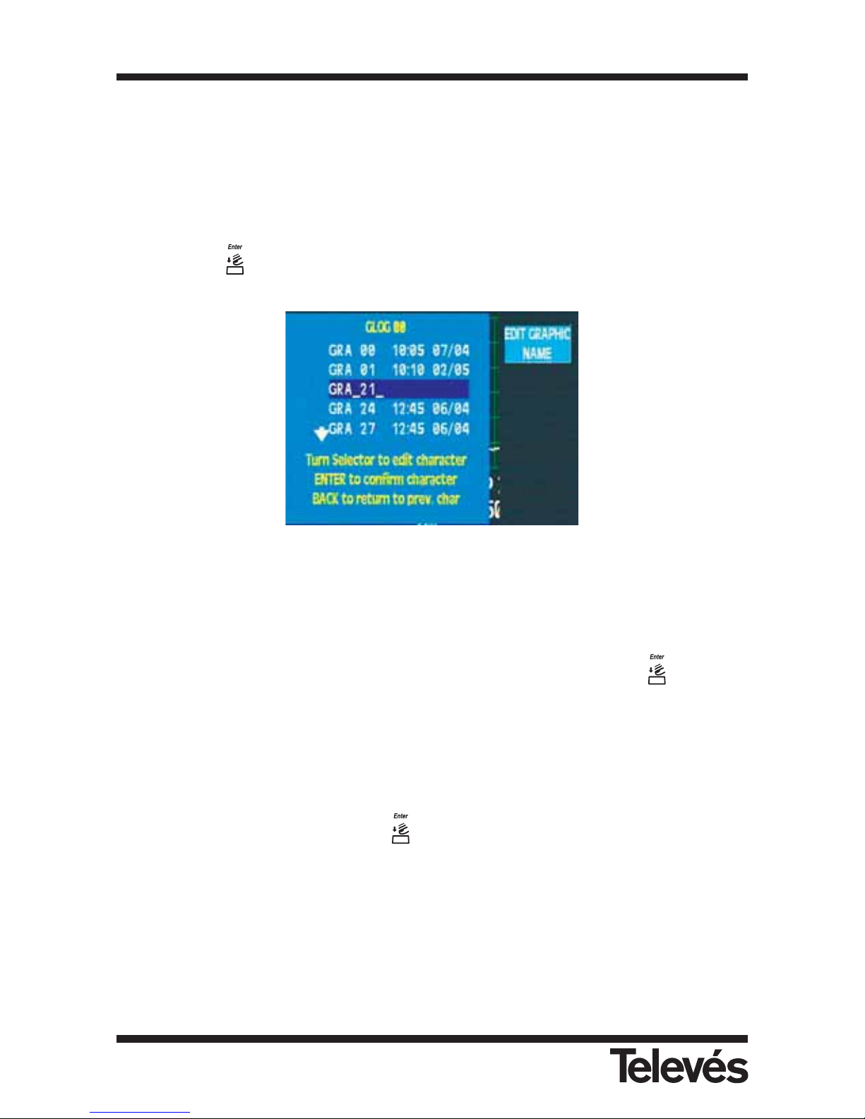
3.3.1.4.4.2.- Edit Name
This lets you change the name of the selected GLOG.
3.3.1.4.4.2.- Edit Graph Name
This option displays a list of the current GLOG's graphs. To change the name, select the graph
and then press .
Figura 37.- Editing the name of a graph
3.3.1.4.4.3.- Erase Graph
With this function you can erase the GLOGS directly together with all the graphs they contain.
It is possible to select 1 or more GLOGs for the erasing process and then press to confirm.
3.3.1.4.4.3.1.- Select Graphs
This option lets you erase the graphs in the selected GLOG. To do so, the graphs are selected
using the rotating knob and by pressing
.
When we have finished, we must press Confirm.
Multimetter FSM 500 Ref. 5903
43
Page 44
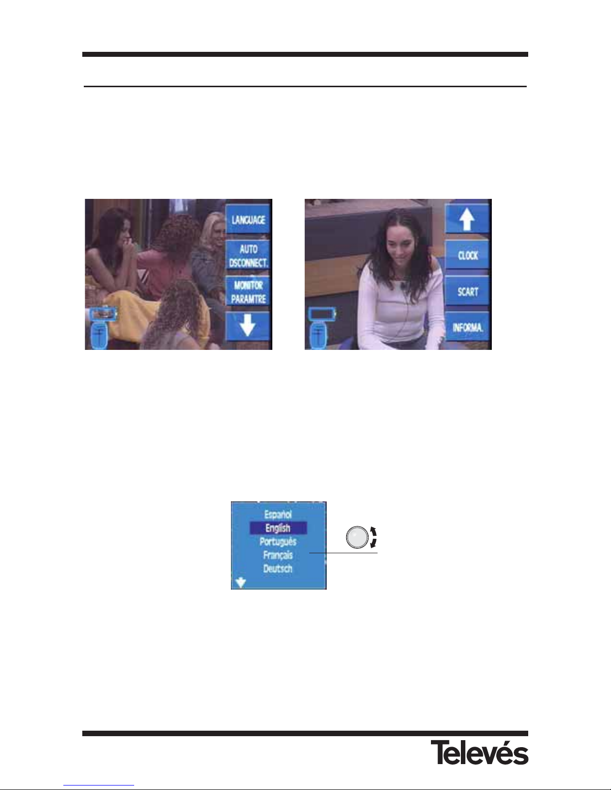
3.3.2.- Equipment configuration
The functions in this menu set all of the parameters that are related to the meter’s configuration.
All of the windows that open in the different functions in the “Equipment Configuration” menu
can be closed by using the Clear button.
Within this option, there is also the following submenu (if we press the arrow below, the
following options will appear, as can be seen in the second picture):
Figure 38.- Equipment configuration options
3.3.2.1.- Language
The FSM 500 allows you to select the menu language. The languages that are available are:
Spanish, English, Portuguese, French, German and Italian. The window that appears when this
menu is selected looks as follows:
Figure 39.- Language selection for the menus
3.3.2.4
3.3.2.5
3.3.2.6
3.3.2.1
3.3.2.2
3.3.2.3
Multimetter FSM 500 Ref. 5903
44
Page 45
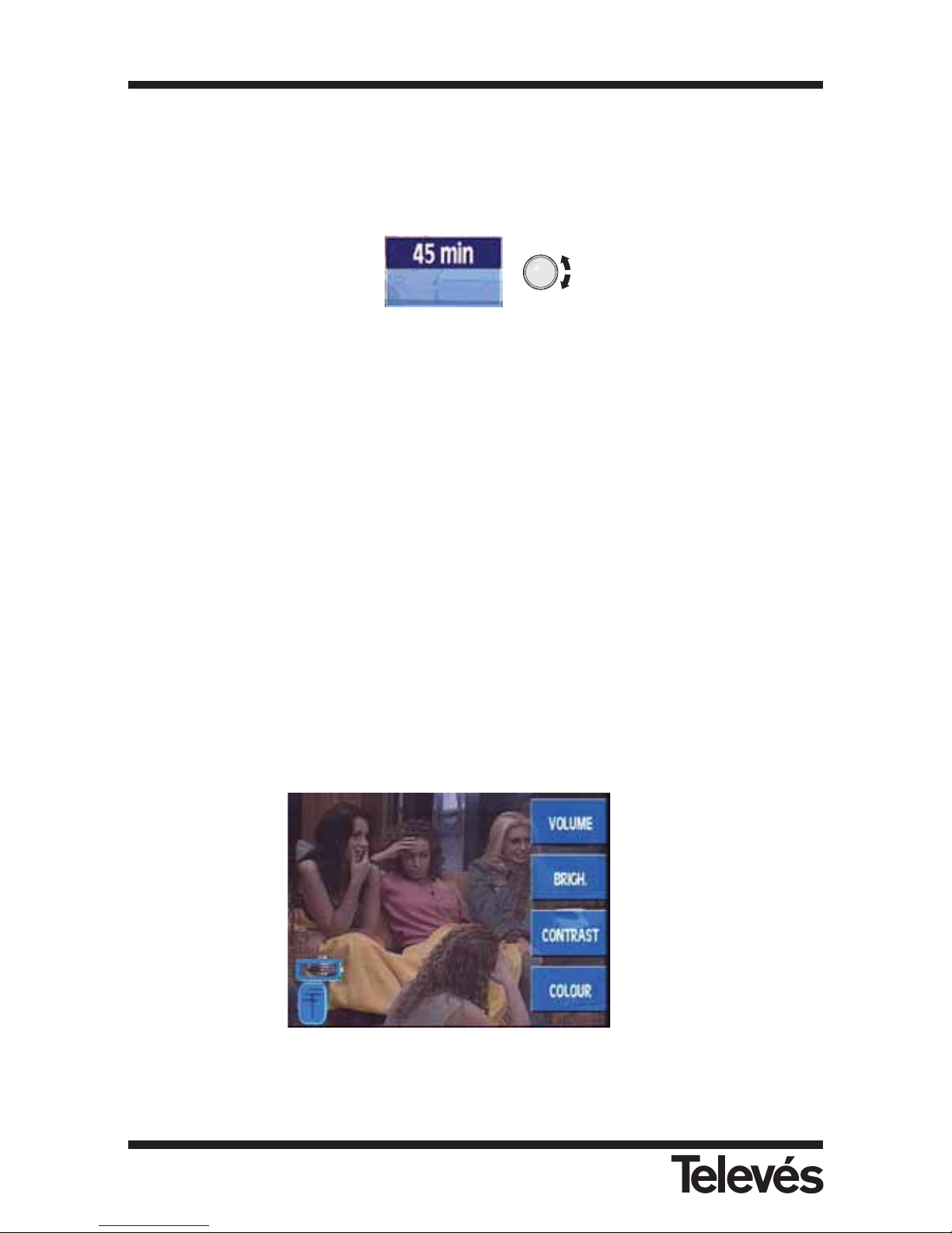
3.3.2.2.- Automatic shut-down
The equipment has the option of automatically turning off once a certain programmable time of
inactivity has elapsed. This period of inactivity that can be selected ranges from 1 to 59
minutes. The user can also disable this function (OFF). The equipment has a default value for
this period of inactivity of 15 minutes.
Figure 40.- Time left until shut-down
When the time programmed by the user has elapsed and the equipment has not been used, a
message will appear onscreen "Auto dsconnect", together with an audio signal which will
indicate that the equipment is about to shut-down. If no button is pressed, the message will
appear 6 times and then the equipment will shut down.
Note: Once the time that has been programmed by the user has passed, if a
Macromeasurement is being carried out, the meter will wait until the end of this
process before continuing with the disconnection.
3.3.2.3.- Monitor
This menu consists of the functions that control the monitor’s parameters: the volume,
brightness, contrast and saturation. The window that appears when these functions are
enabled is very similar in all cases. It consists of a horizontal bar. The length of this bar varies
according to the level of the parameter that is selected. To change the value of these
parameters, use the rotating knob and to close the windows use the Clear button.
Figure 41.- Monitor options
3.3.2.3.1
3.3.2.3.2
3.3.2.3.3
3.3.2.3.4
Multimetter FSM 500 Ref. 5903
45
Page 46
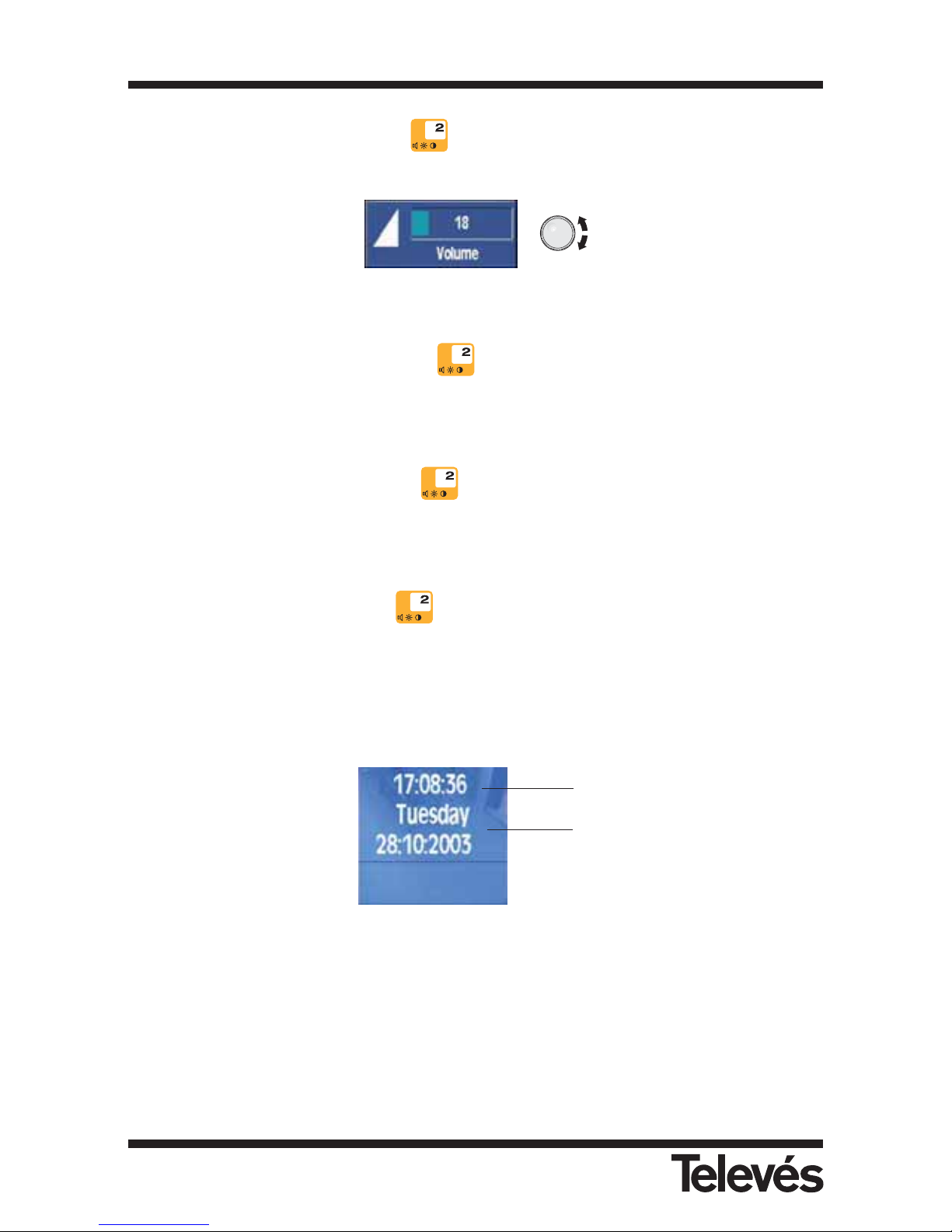
3.3.2.3.1.- Volume (short cut button )
Use the rotating knob to increase or decrease the volume. The volume screen appears as follows:
Figure 42.- Selection of volume
3.3.2.3.2.- Brightness (short cut button )
This increases or decreases the brightness of the picture onscreen. It operates in the same way
as the volume control.
3.3.2.3.3.- Contrast (short cut button )
This increases or decreases the contrast of the picture onscreen. It operates in the same way
as the volume control.
3.3.2.3.4.- Color (short cut button )
This increases or decreases the color of the picture onscreen. It operates in the same way as
the volume control.
3.3.2.4.- Clock
The window that appears as follows:
Figure 43.- Clock option
It is possible to vary the time (the hour and minutes) and the date (day, month and year). To do
so, the user needs to press the rotating knob and the hour (in the time) will appear highlighted
(dark blue square). If the user turns the knob the time will vary. When the knob is pressed again,
the hour is confirmed and the minutes are hightlighted. If the knob is pressed for the third time,
the day is highlighted, then the month and finally the year. The name of the day will vary
automatically according to the corresponding month and year.
To close the clock window press the Clear button.
Time
Date
Multimetter FSM 500 Ref. 5903
46
Page 47
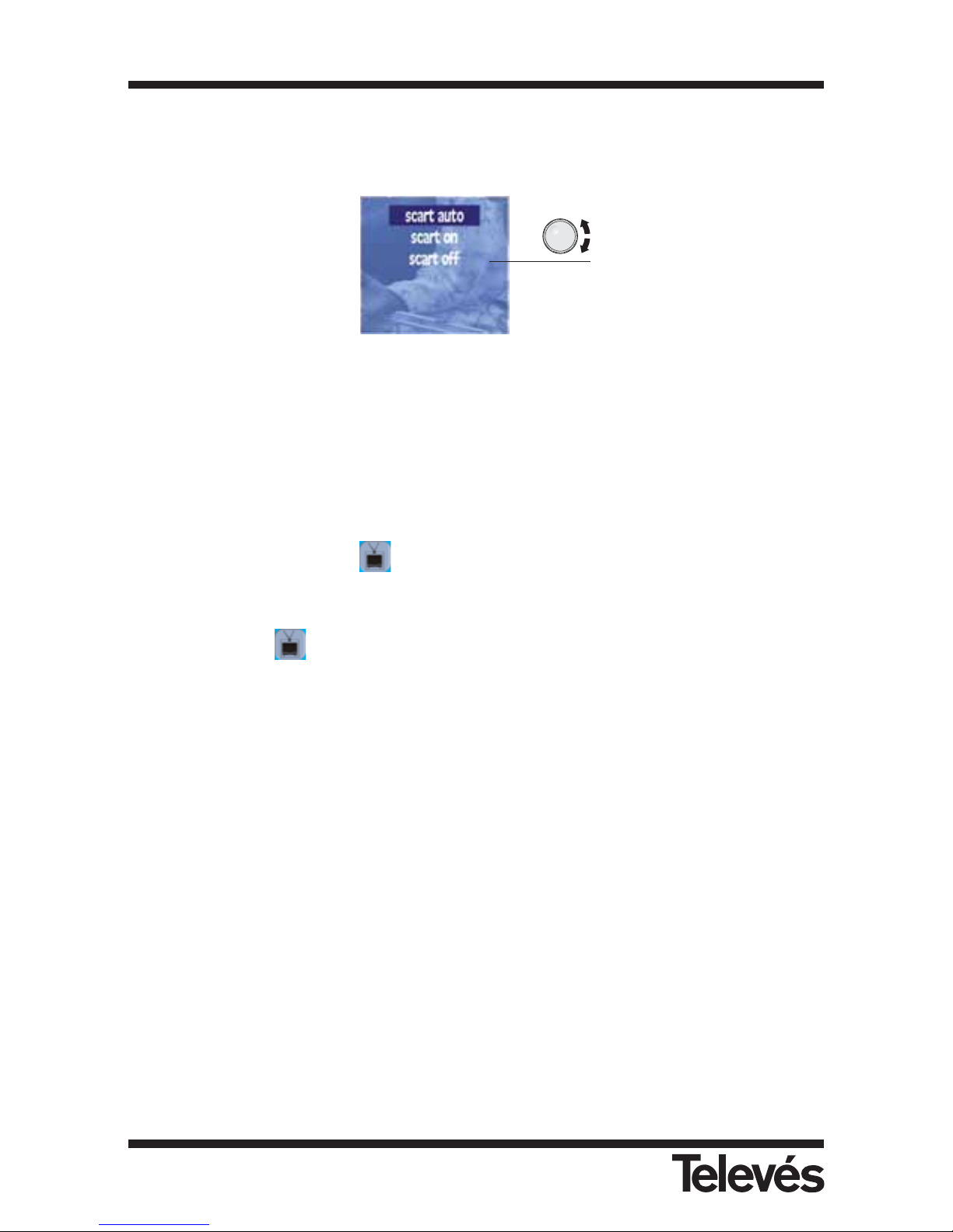
3.3.2.5.- Scart
A window opens that allows you to select the control of the signals of the SCART:
Figure 44.- Scart options
Scart auto: Normal operating mode of the scart, in other words, when there is a signal in the
scart, it is automatically seen onscreen. It is important to note, however, that this
function depends on the device being used, and therefore, it may be that,
although a device with a video signal is connected to the scart, this may not
appear onscreen. In this case, select the Scart on option. When the equipment
is in Scart auto mode, and this detects a video signal in the scart, the antenna
icon disappears from the screen (terrestrial or satellite) and instead, a television
icon will appear: . The user therefore knows that the picture onscreen comes
from the scart and not from the antenna.
Scart on: This forces the signal input from the scart connector. In this case, the television
icon will always appear instead of the antennas, both when there is a signal
from the scart and when there isn’t.
Scart off: This disables the scart.
To close the window press the Clear button.
Notes:
- It is important to check the status of the scart mode selection, as if it is in Scart on mode, we
will not be able to see the TV signal onscreen when we want to use the equipment in normal
mode (input signal in the RF connector).
- If there is a signal in the scart, and if this is being seen onscreen (auto or on), the meter will
carry on functioning normally as regards the measurements. In other words, the
measurements that are carried out will correspond to the signal at the input of the “F”
connector. It is not possible to take measurements of the scart signal. The same will happen
with the spectrum representation of the signal, in other words, although the picture that we
have onscreen will come from the scart, the spectrum will correspond to the RF input signal.
The only exception is the representation of the synchronism burst; this will indeed
correspond to the synchronism of the scart’s signal.
Multimetter FSM 500 Ref. 5903
47
Page 48
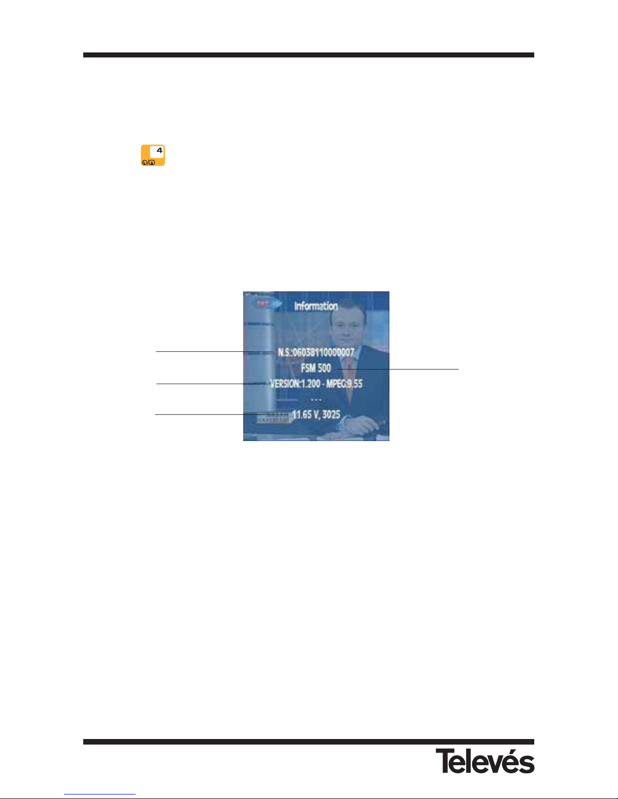
- If the meter has a digital measurement window open (Power or C/N) it will be impossible to
see the scart signal, although this may be in auto mode. Therefore, if you wish to see the
scart signal, make sure that the meter is not carrying out a digital measurement.
- If you wish to see any TV signal onscreen, it is worth remembering that you can remove all the
menus from the screen by using the Clear/Menu button, and the measurement windows by
using the button or by accessing the Viewing Mode menu.
3.3.2.6.- Information about the equipment
When this function is selected, a window will open which will display information about the
equipment, as can be seen below:
Figure 45.- Window displaying equipment information
3.3.2.6.1- Update
Using this option we can load the licence number in order to activate an options packet.
Serial number
Model
Software version
Voltage measured
in the battery
Multimetter FSM 500 Ref. 5903
48
Page 49

3.3.2.6.2.- Changing the battery
The FSM 500 offers two possibilities when changing the battery:
A) A possibility is to change the battery for another with a different capacity. The equipment
comes with a Ni-MH 6 AH battery which will provide the equipment with more than 4 hours
of battery life.
When the installer wishes to change the batteries, it is necessary to inform the equipment
so that it can modify the charging and discharging algorithm so as to optimize their lifespan
and duration while in use.
Below is the process that must be followed when substituting the batteries:
1.- Substitute the battery by following the steps described in section 5.1.- Changing
the battery.
2.- Select the Changing the battery function. Select the appropriate option (either
Ni-MH 3,5 AH or Ni-MH 6 AH). A message will appear onscreen asking for
confirmation of the change. To confirm the change, press the button. If any
other button is pressed, the change will be cancelled.
Figure 46.- Information window for changing the battery
Note: This function must only be used when a battery change has really
taken place, as it affects a series of parameters that are necessary for
the control of the charging and usage of the batteries. If these vary,
they will decrease the lifespan and the duration of the batteries. It is
vitally important, in this model, to indicate the type of battery that is
being introduced, as well as to check that it coincides with the
selected type in the side microswitches (37).
3.- Change the position of the battery’s configuration microswitches. At first the
microswitch P5 is above, and P6 below, and it is necessary to change the position
of these microswitches, in other words, P5 should be below and P6 above. Below,
is a diagram on how the microswitches should be placed according to the type of
battery:
Multimetter FSM 500 Ref. 5903
49
Page 50
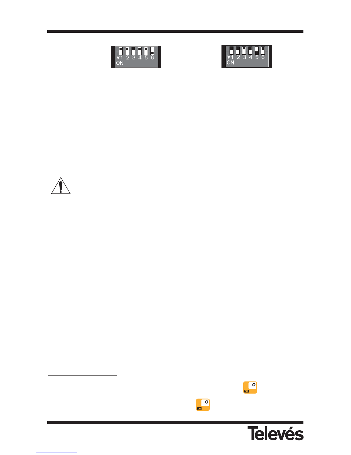
Standard battery Ni-MH 3,5 AH Long life battery Ni-MH 6 AH
Figure 47.- Configuration of the switches according to the type of battery
4.- Switch the equipment off
5.- Disconnect the equipment from the mains
B) Another possibility is to substitute the battery for another with the same characteristics.
In this case, you only need to carry out steps 1 and 2 as described in the previous section.
Warning about battery changing
· When removing or introducing the batteries, make sure that the meter is switched off.
· If you remove the battery, when you put it back in again, make sure that it is connected
correctly.
· If you are using metal tools for the installation of the batteries, you must isolate them, as
they could cause a shortcircuit.
· Do not connect the positive terminal to the negative terminal of a battery with a metal
object, the battery could re-heat, emit hydrogen gas, undergo spillage, burn or explode.
· The user should use batteries provided by Televés, which are appropriate for this
equipment.
3.3.2.6.3.- Battery regeneration
The FSM500 disposes of a function which carries out a recycling of the batteries. This option
regenerates the batteries when the duration of the batteries has dropped considerably.
This process should only be carried out if the powering without supply from the mains
has been reduced drastically since a repeated use of this function can shorten the
battery life.
For the regenerating process to take place, it is necessary to exter
nally power the meter
continuously for 15 hours.
To start this process, the user must be inside this menu and then press . Another screen
appears which explains the process and by pressing again, the process begins. If any
Multimetter FSM 500 Ref. 5903
50
Page 51
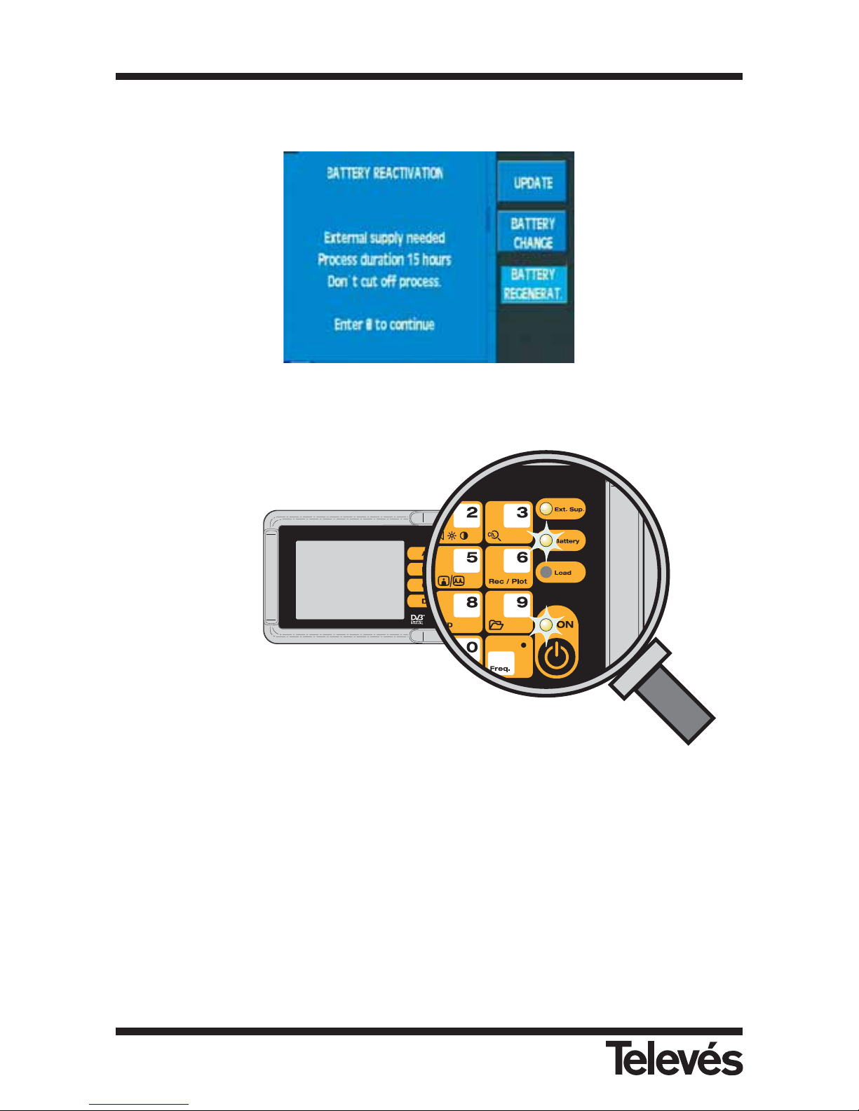
other key is pressed, the meter returns to its previous state.
Figura 48.- Battery regeneration
When the charging process begins, the meter will switch off while the battery light and the ON
light will flash on and off.
Figura 49.- Meter indication
Once this process has finished, the ON light will switch off and the battery light will switch on.
If, after this process, it is not possible to see an increase in the battery life, it is advisable to
change the batteries.
Multimetter FSM 500 Ref. 5903
51
Page 52
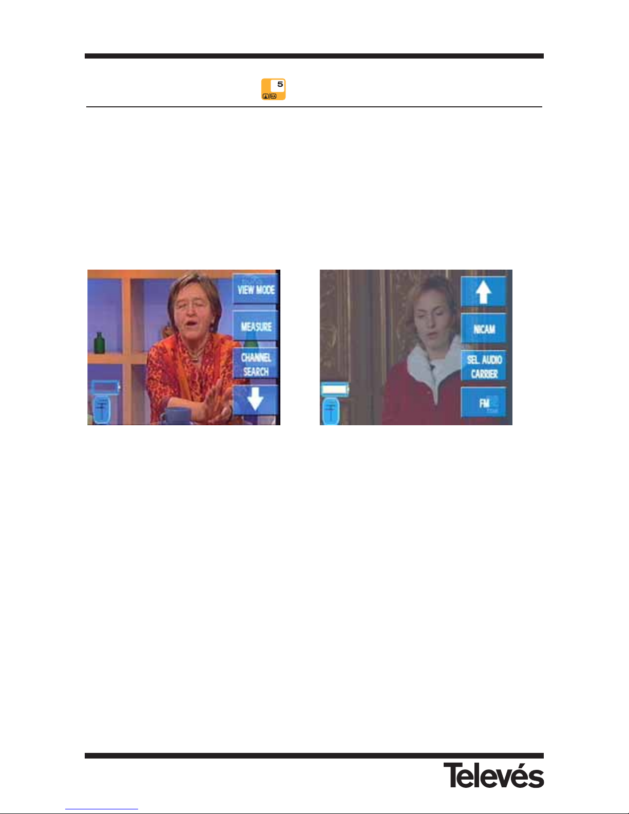
3.3.3.- TV mode (short cut button )
When this menu is selected, the equipment switches automatically to TV mode, in other words,
the user will see the demodulated television signal of the tuned channel onscreen.
The corresponding submenu is the following:
3.3.3.1.- Viewing mode
The functions of this menu let you choose the elements that you wish to see on the screen of
the meter; the bar indicating the level, the representation of the synchronism burst and the
measurement window.
Figure 50.- Viewing mode options
3.3.3.1.1. Bar
On the upper part of the screen, there is a horizontal bar which indicates the signal level of the
tuned frequency in green (if it is in frequency tuning) or the video carrier level (if it is in channel
tuning). As well as the signal level, other additional information may appear; if a V/A
measurement is being carried out, a red bar will appear on top of the green bar which indicates
the audio carrier level, and if the C/N is being measured, the noise level that is measured will
appear in red. This is explained in greater detail in the corresponding sections.
If this option is pressed again, the bar disappears.
3.3.3.4
3.3.3.5
3.3.3.6
3.3.3.1
3.3.3.2
3.3.3.3
Multimetter FSM 500 Ref. 5903
52
Page 53
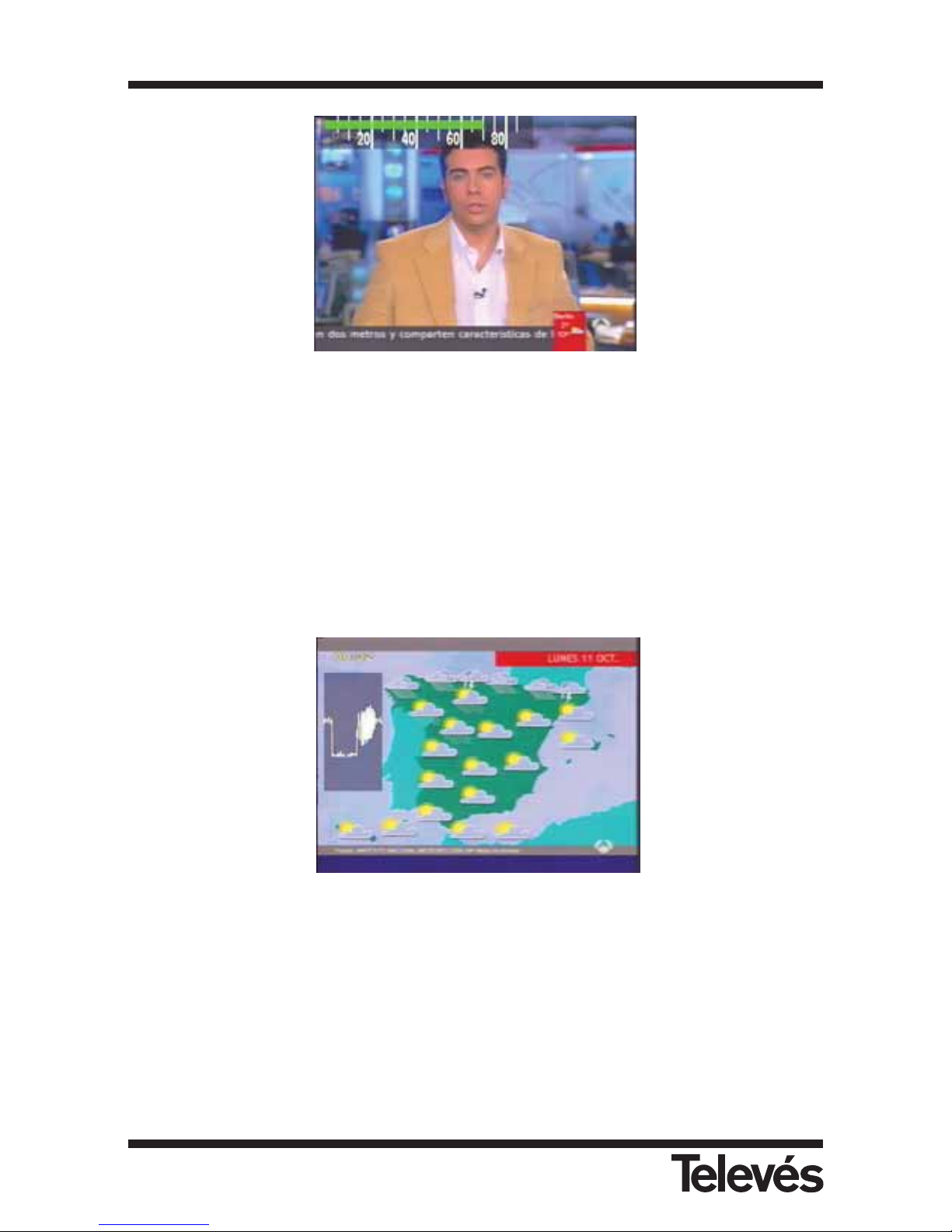
Figura 51.- Indication via bars
3.3.3.1.2.- Synchronism
This option displays the representation of the synchronism burst on the left-hand side of the screen.
If a digital measurement is being carried out (power, C/N, BER, MPEG), it will not be possible
to see the synchronism burst, as the meter supposes that the tuned channel is digital and
therefore does not represent this burst.
If this option is pressed again, the synchronism burst disappears.
Figura 52.- Synchronism indication
As you can see, the backgrounds of the level bar and the synchronism burst are transparent so
that they do not interfere with the image onscreen.
Multimetter FSM 500 Ref. 5903
53
Page 54
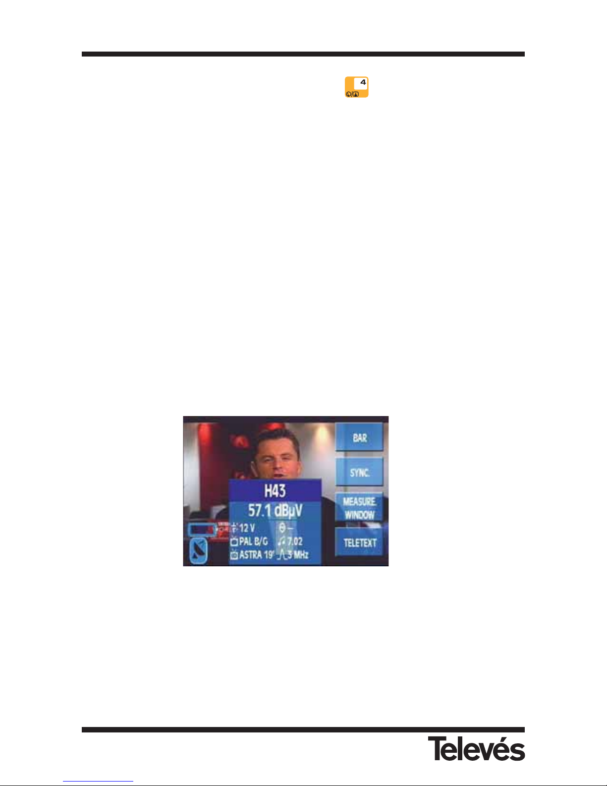
3.3.3.1.3.- Measurements window (short cut button )
When this option is selected, the window that corresponds to the last measurement that was
carried out, opens. In other words, if the last measurement that was carried out was the C/N (for
example), the C/N window will open and the C/N measurement will be carried out in the tuned
channel.
As was the case before, to close the window, you simply need to select the same option again.
However, if the level measurement appears, there are two different windows that represent this
measurement: the abbreviated and the extended windows. The first of these displays the tuned
frequency (or channel) and the measurement. The extended window displays this information
too, but also displays some information on the audio carrier, the colour standard, the channel
plan, the resolution filter, the current that is being supplied to the preamplifiers and if the 22 MHz
tone is enabled.
The first time that this option is pressed, the abbreviated window appears, if this option is
pressed again, the extended window appears, and if it is pressed again, this option closes.
These windows will be explained in greater detail in the Measurements-Level section.
It is also necessary to note that the short cut button is not operative when a digital
measurement is selected, in other words, once a digital measurement window is opened, it will
not be possible to close it, the user will be able to substitute it for another, but there will always
be a measurement window open. This is because as there is nothing onscreen about the TV
signal, it is not necessary to close all the windows, as the screen would turn black and this
could cause confusion.
Below, you can see an example of the screen with all of these elements on display:
Figure 53.- Extended window
3.3.3.1.1
3.3.3.1.2
3.3.3.1.3
3.3.3.1.4
Multimetter FSM 500 Ref. 5903
54
Page 55
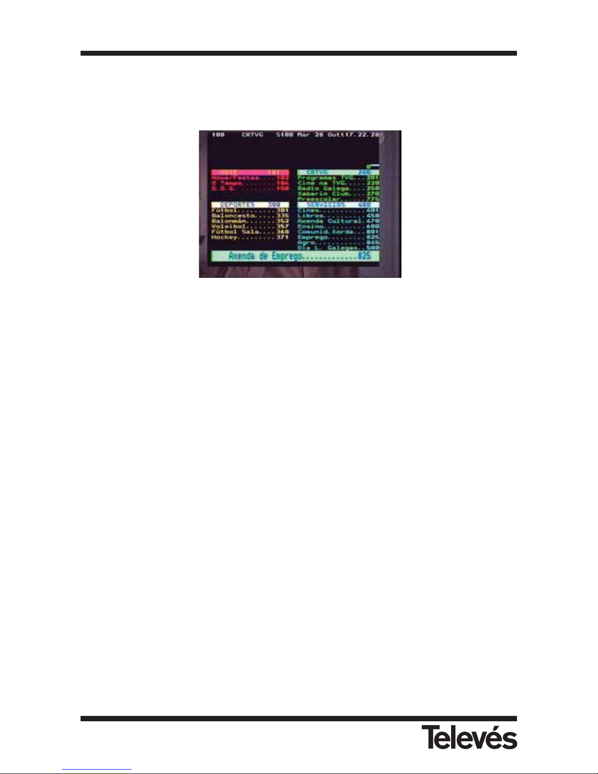
3.3.3.1.4.- Teletext
When this function is selected, the teletext information of the tuned channel will appear onscreen
(if the channel does not dispose of this information, NO TTX will appear). The representation level
of the teletext function is 1.5
Figure 54.- Teletext window
We can travel through the teletext pages using the rotating knob. We can access a teletext page
by pressing Freq. and then entering the page number. To return to the picture from the TV
signal, you need to press the Teletext button again.
3.3.3.2.- Measurements
When we select a specific measurement, a window will open which will display the
measurement just carried out and the frequency (or channel) of the measurement, which
corresponds to the frequency (or channel) that the user has tuned.
It is possible to vary the tuned frequency as you watch the measurement window. In this way,
we can carry out the same measurement in consecutive frequencies (or channels) very simply.
To vary the frequency, use the rotating knob or the number pad. To enter the frequency with the
keyboard, press the Freq. button until the frequency information that appears in the window is
erased. Now you will be able to enter the frequency using the keyboard. It is important to
remember at this point that to insert the dot that separates the decimals, you also need to use
the Freq. button.
Multimetter FSM 500 Ref. 5903
55
Page 56
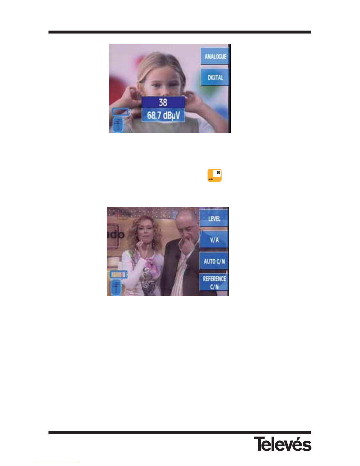
Figure 55.- Measurement menu
3.3.3.2.1.- Analogue measurements (short cut button )
The corresponding submenu is as follows:
Figure 56.- Analogue measurements
3.3.3.2.1.1.- Level
If the channel tuning mode has been selected, this function will measure the carrier level of the
tuned channel. If, however, the frequency tuning mode has been selected, the signal level of the
tuned frequency will appear in the window.
As we have already seen in the Viewing mode - Measurements section, there are two possible
windows for the level measurement (abbreviated and extended). Below you can see an example
of a level measurement window in its abbreviated form:
3.3.3.2.1.1
3.3.3.2.1.2
3.3.3.2.1.3
3.3.3.2.1.4
3.3.3.2.1
3.3.3.2.2
Multimetter FSM 500 Ref. 5903
56
Page 57
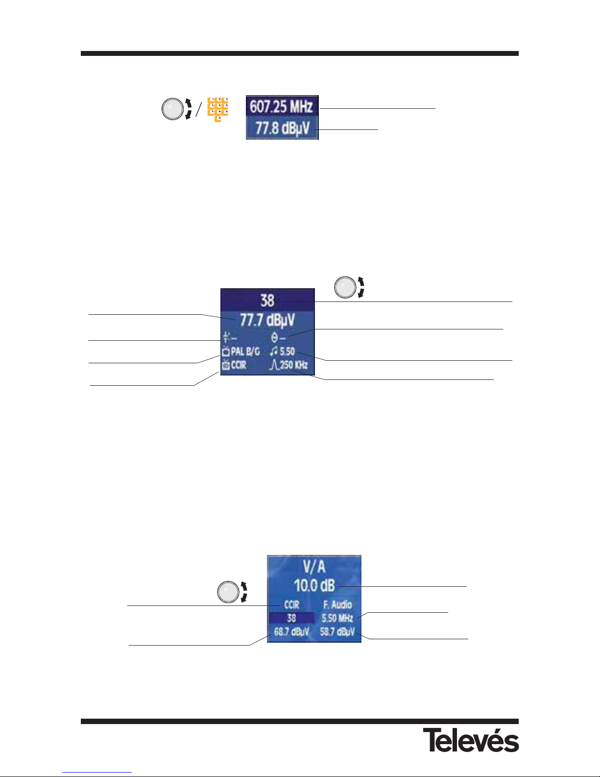
Figure 57.- Abbreviated form
You can vary the frequency by using the rotating knob (in the terrestrial band with a resolution
of 50 KHz and in the satellite band 100 KHz), or by using the number pad.
In the extended window, the following information appears:
Figure 58.- Extended form
When in Viewing - Measurements mode, if the extended window is selected for the level
measurement then this will always be used when carrying out this measurement, until we
change the viewing mode.
3.3.3.2.1.2.- V/A (only the terrestrial band)
The window that appears when carrying out this measurement is the following:
Figure 59.- V/A measurement. Channel tuning
Selected channel
plan
Signal level in the tuned
frequency
V/A measurement
Audio carrier
Audio carrier level
Channel tuning mode:
information on the tuned channel
Signal level
Preamplifier powering (OFF)
Colour standard
Channel plan
22 KHz tone. In this case, it is disabled
Audio carrier (MHz above the video
carrier)
Bandwidth of the measurement filter
Frequency tuning mode:
information on the tuned
frequency
Signal level
Multimetter FSM 500 Ref. 5903
57
Page 58
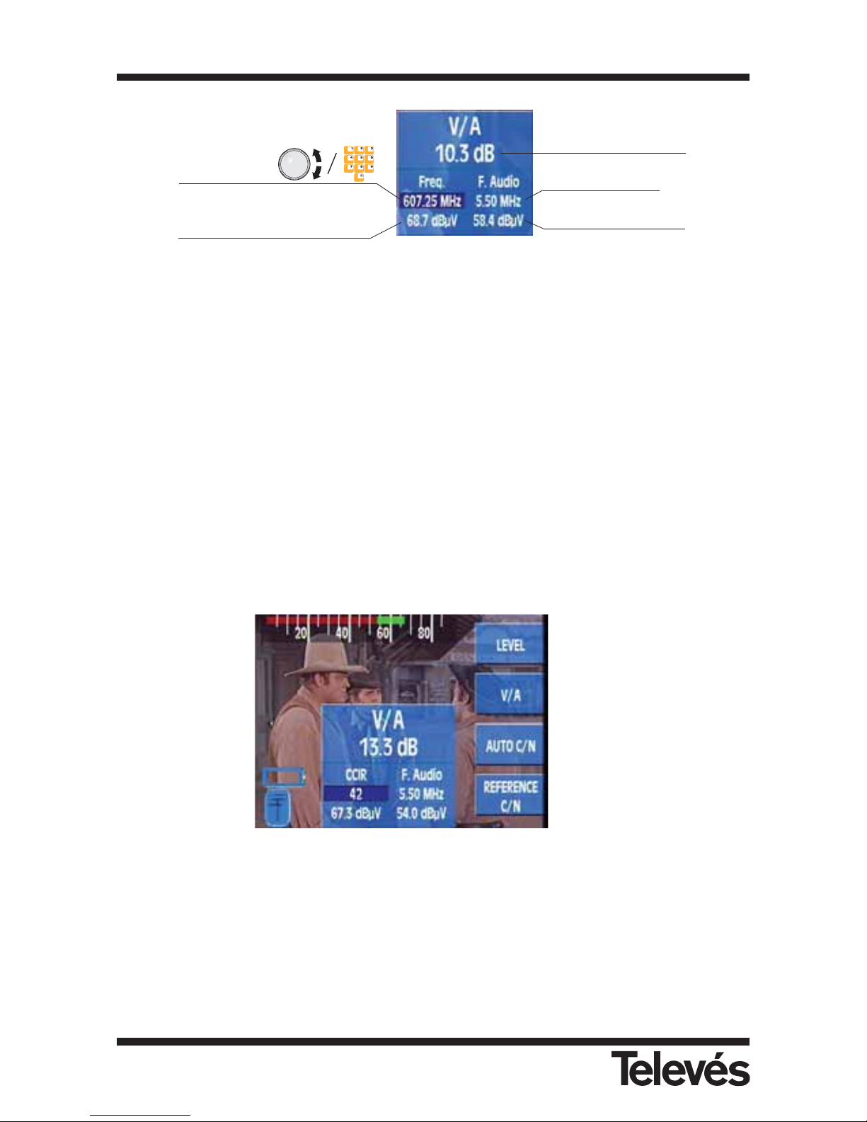
Figure 60.- V/A measurement. Frequency tuning
The tuned frequency is taken as the video carrier, in other words, it is where the video level is
measured. The audio carrier level is taken to be as many MHz higher as indicated in the Audio
information that appears onscreen (5.50 in the example). By pressing the Freq. button, the
information on the tuned frequency is highlighted. Once this has been done, we can vary the
tuning by using the rotating knob or the number pad.
If we press the Chan. button, the information on the tuned channel will appear. The frequency
that is used to carry out the video level measurement will be the video carrier of the channel
that the equipment searches for automatically.
Therefore, when the equipment is in frequency tuning mode, it is the user’s responsibility to
make sure that the tuned frequency is really the video carrier of the channel that the V/A
measurement is to be carried out on, in order for the measurement to be totally correct.
If the level bar is visible when the V/A measurement is being carried out (see section 3.3.3.1.1.-
Bar), two overlapping bars will appear, one in green which indicates the video carrier level
(channel tuning) or the tuned frequency level (frequency tuning), and the other in red which
indicates the audio carrier level.
Figure 61.- Indication of V/A using the bars
3.3.3.2.1.3.- Automatic C/N
When this function is selected, a window with the carrier / noise ratio will appear automatically
onscreen. The window that appears is the following:
3.3.3.2.1.1
3.3.3.2.1.2
3.3.3.2.1.3
3.3.3.2.1.4
Tuned
frequency
Signal level in the tuned
frequency
V/A measurement
Audio carrier
Audio carrier level
Multimetter FSM 500 Ref. 5903
58
Page 59
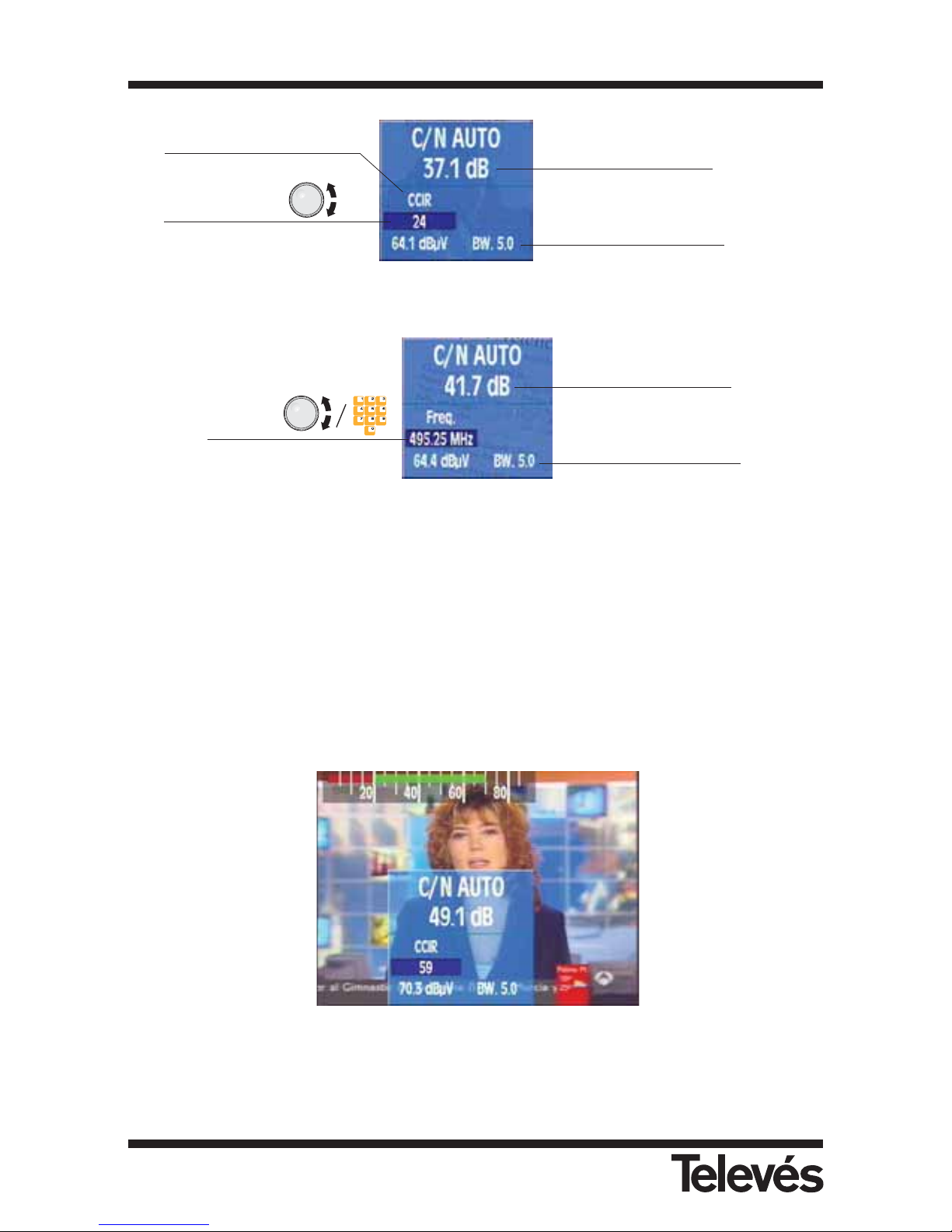
Figure 62.- Automatic C/N measurement. Channel tuning
Figure 63.- Automatic C/N measurement. Frequency tuning
If in channel tuning mode, you will be able to see the channel with the carrier that is being used
to carry out the level measurement. As has already been explained in the section regarding the
V/A ratio measurement, if the equipment is in frequency tuning mode, the level measurement
will be carried out in the frequency that the user has tuned, and so it will be the user’s
responsibility to make sure that this frequency corresponds to the real channel carrier.
If the level bar is visible when the C/N measurement is being carried out (see section 3.3.3.1.1.-
Bar), two overlapping bars will appear, one in green which indicates the video carrier level
(channel tuning) or the tuned frequency level (frequency tuning), and the other in red which
indicates the measured noise level.
Figura 64.- Indication of C/N via bars
This function has the following submenu:
Tuned
frequency
Channel bandwidth
C/N measurement
Tuned channel
Channel bandwidth
C/N measurement
Selected channel plan
Multimetter FSM 500 Ref. 5903
59
Page 60
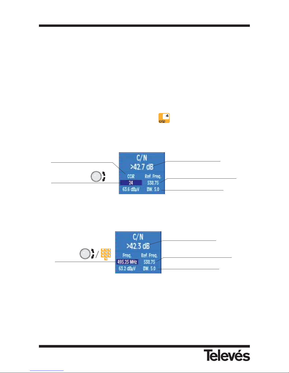
3.3.3.2.1.3.1.- Channel BW
When this option is pressed, a small window opens on top of the previous window, displaying
the value of the video bandwidth which will be taken into account when automatically
compensating the noise (we recommend 5 MHz for this measurement). As the user turns the
rotating knob, the different options will appear. To select a value, press this knob.
3.3.3.2.1.4.- Referenced C/N
When this function is selected, the video signal automatically disappears from the
screen. This is because the equipment has to carry out the noise measurement in
the reference frequency. Because of this, the button is not enabled.
The window that appears when this function is selected is the following:
Figura 65.- Referenced C/N measurement. Channel tuning
Figure 66.- Referenced C/N measurement. Frequency tuning
If in channel tuning mode, you will be able to see the channel with the carrier that is being used
to carry out the level measurement. As has already been explained, if the equipment is in
frequency tuning mode, the level measurement will be carried out in the frequency that the user
has tuned, and so it will be the user’s responsibility to make sure that this frequency
corresponds to the real channel carrier.
To carry out this measurement, it is necessary to indicate two parameters; the frequency at
Frequency at which the
noise level is measured.
Tuned
frequency
Channel bandwidth
C/N measurement
Tuned channel
Channel bandwidth
C/N measurement
Selected channel plan
Frequency at which the
noise level is measured.
Multimetter FSM 500 Ref. 5903
60
Page 61
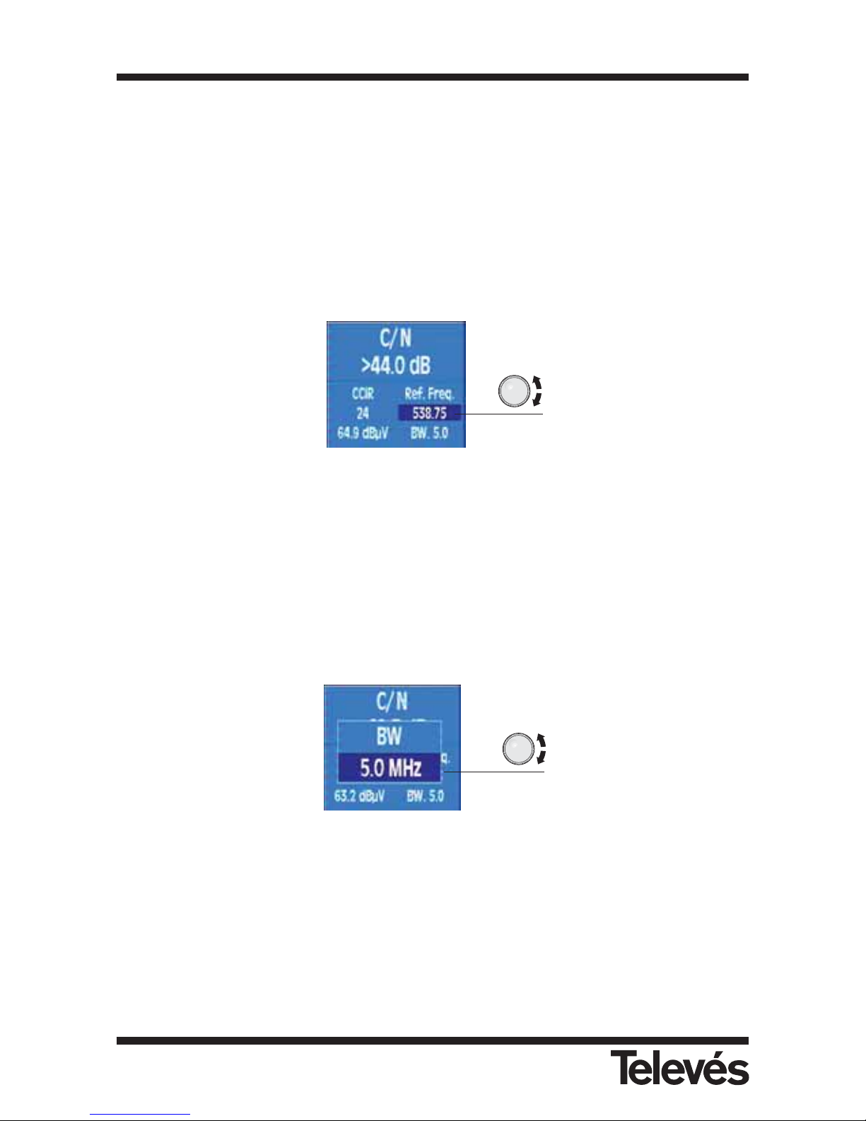
which you want to measure the noise level (reference frequency) and the channel bandwidth.
To do so, this function has the following submenu:
3.3.3.2.1.4.1.- Reference frequency
By pressing this option, the noise frequency is highlighted in the window (dark background).
You can vary the noise frequency by using the rotating knob. Once the reference frequency has
been selected, if you press the Freq. button, the current frequency is erased and the you can
enter the frequency that you want by using the number pad.
Figure 67.- Reference frequency
3.3.3.2.1.4.2.- Channel BW
When this option is pressed, a small window appears over the previous window which displays
the video bandwidth that will be taken into account when automatically compensating for the
noise (we recommend 5 MHz). When rotating knob is turned, the different options appear. To
select the value that you want, simply press the rotating knob.
Figure 68.- Channel bandwidth
Multimetter FSM 500 Ref. 5903
61
Page 62
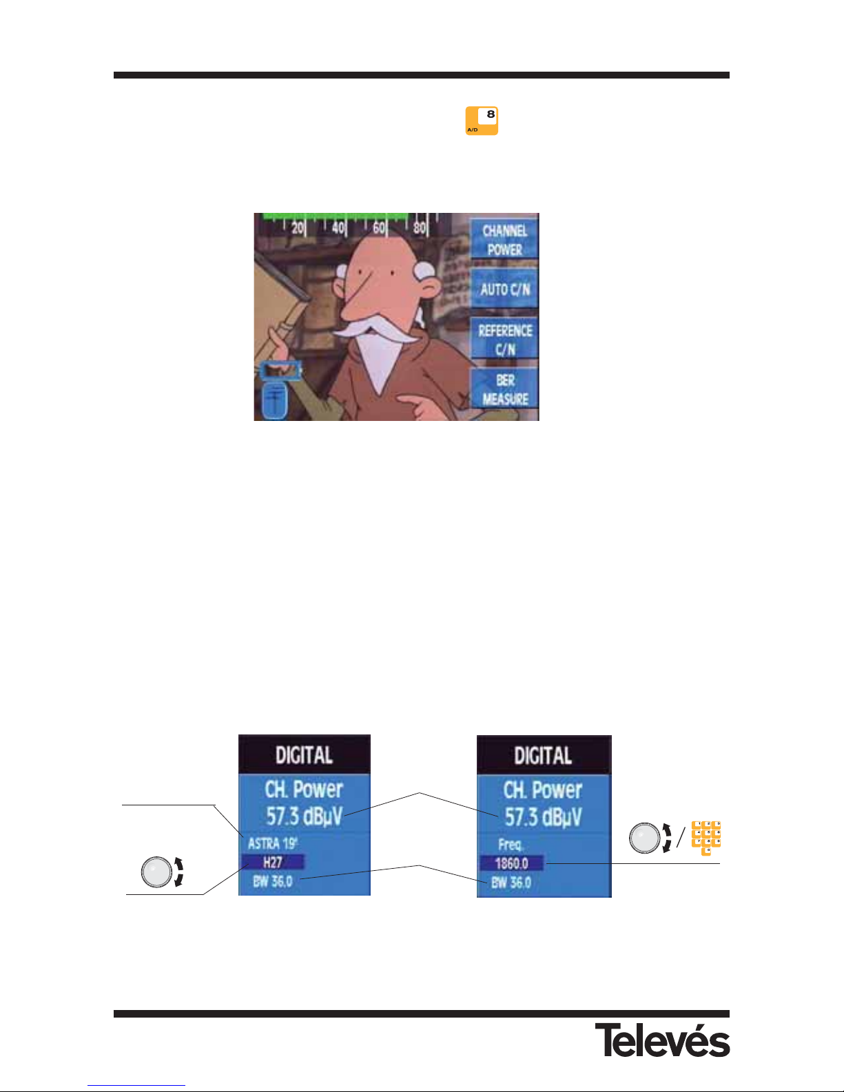
3.3.3.2.2.- Digital measurements (short cut button )
When a digital measurement is selected, the image from the TV signal will disappear from the
screen, and a warning message will appear that indicates that this is a digital measurement.
Figure 69.- Options for digital measurements
3.3.3.2.2.1.- Channel power
If the equipment is in TV mode, when this function is selected, the image from the
TV signal will automatically disappear from the screen, and a warning message will
appear that indicates that this is a digital measurement, as can be seen in the
following figure.
If the frequency tuning mode is selected, the tuned frequency will be taken as the intermediate
frequency of the digital channel. As in the measurements that have already been explained,
the user can use the rotating knob or the number pad to vary the frequency (or the channel) in
which the measurement is to be carried out. The power measurement will be carried out by
using the bandwidth that was entered by the user and by using its value that appears in the
measurement window.
Channel tuning (satellite) Frequency tuning (satellite)
Figure 70.- Digital channel power
Selected channel
plan
Power
measurement
Channel
bandwidth
Tuned channel
Tuned
frequency
3.3.3.2.2.1
3.3.3.2.2.2
3.3.3.2.2.3
3.3.3.2.2.4
Multimetter FSM 500 Ref. 5903
62
Page 63
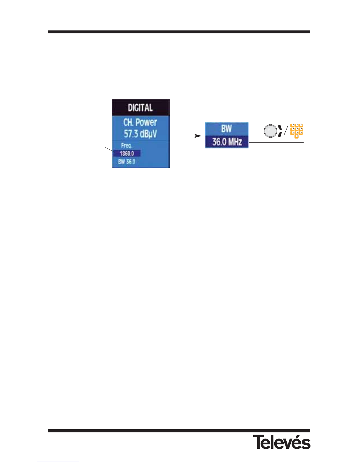
To change this parameter, the following submenu appears:
3.3.3.2.2.1.1.- Channel bandwidth
If this option is pressed, the value of the bandwidth is selected in the channel power window.
You can change this value by using the rotating knob:
Figure 71.- Bandwidth
3.3.3.2.2.2.- Automatic C/N
This function is the same as the automatic C/N in the analogue channels. Above the window, it
is possible to see that this is a digital measurement.
3.3.3.2.2.3.- Referenced C/N
This function is the same as the referenced C/N in the analogue channels. Above the window,
it is possible to see that this is a digital measurement.
3.3.3.2.2.4.- BER measurement
The submenu of this function varies, depending on the band that is selected (either terrestrial
or satellite).
When the BER is being measured, the Network Provider information, the Number of Services
and the name of the Services will be displayed at the bottom of the window.
Tuned frequency.
This will be taken as
the channel central
frequency
Channel BW
Channel BW
Multimetter FSM 500 Ref. 5903
63
Page 64
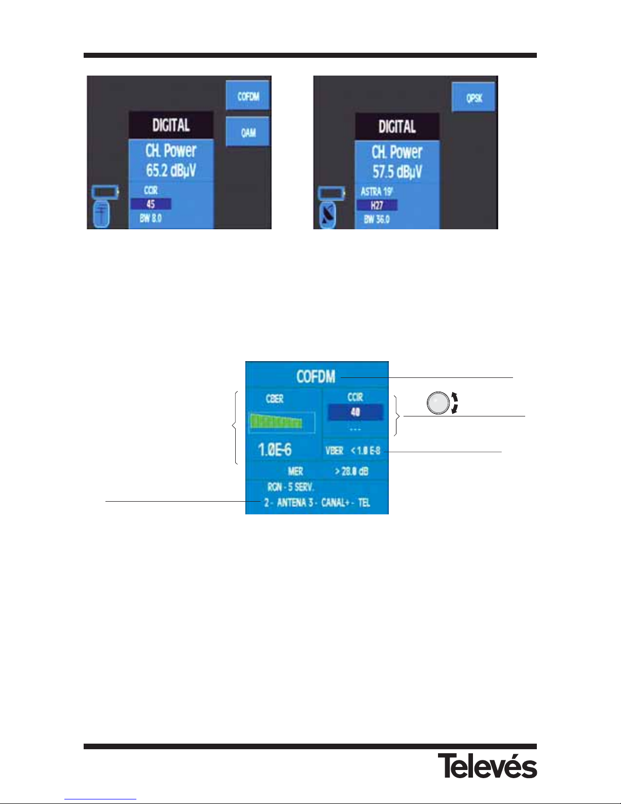
Terrestrial band Satellite band
Figure 72.- Options for the BER measurements
The window that opens when any of the modulations is selected is the same, however the type
of modulation varies:
Figure 73.- BER measurement window
To indicate if the CBER measurement is at an acceptable threshold, the colour of the bars
varies. When the CBER is red, this indicates that the signal quality is bad. When the CBER
measurement is yellow, this indicates that the signal quality is acceptable but it would be better
to improve it. If the CBER measurement is green, this indicates that the signal quality is good.
It is very important to take into account that the CBER parameter determines quite clearly
the quality of the installation. This is why we have simplified the interpretation of this
parameter with these colours. The VBER is a parameter that has practically only got two
states, either very good or very bad, which makes it difficult to use to appropriately
evaluate the installation. This is why we recommend using the CBER status to assess the
quality of the installation (it should be a small as possible).
If the meter does not dispose of this option, in the MER measurement, "Option" will appear.
BER before Viterbi
Available services
BER after Viterbi
While the meter is unlocked, the
following message will appear:
UNLOCK.
After a few seconds, the
message will disappear and the
BER measurement appears.
Type of modulation
Tuned channel
3.3.3.2.2.4.1
3.3.3.2.2.4.2
3.3.3.2.2.4.3
Multimetter FSM 500 Ref. 5903
64
Page 65
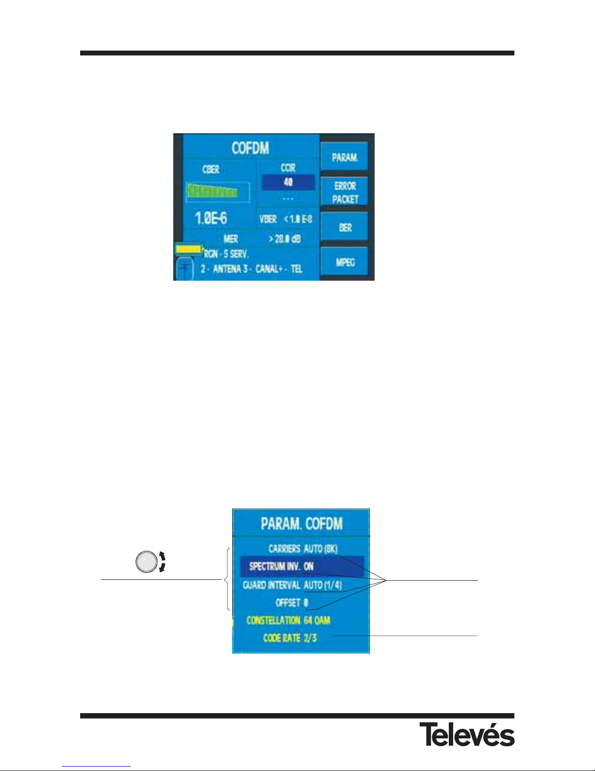
3.3.3.2.2.4.1.- COFDM (only terrestrial band)
Carry out the BER measurement of the digital terrestria signals with COFDM modulation. The
submenu for this type of modulation is the following:
Figure 74.- COFDM measurements
3.3.3.2.2.4.1.1.- Parameters
When this menu is selected, a window appears on top of the BER measurement window which
displays a list of the parameters that can be selected. To vary a specific parameter, use the
rotating knob (selecting and pressing), a window will appear with a list of all the possible values
for this parameter. The parameters tha can vary in COFDM are: Number of carriers (2K, 8K,
AUTO), Spectrum Inversion (ON, OFF, AUTO), Guard Interval (1/32, 1/16, 1/8, 1/4, AUTO),
Offset (0, 1/6, 2/6, 3/6, -1/6, -2/6, -3/6, AUTO). When the AUTO option is selected in any of
the parameters, the equipment automatically selects the appropriate option, although the
locking time will increase.
Below is an example of a parameter selection window:
Figure 75.- COFDM parameters
Possible parameters that
can be selected using
the rotating knob
Current parameter
values
Information on the type
of modulation
3.3.3.2.2.4.1.1
3.3.3.2.2.4.1.2
3.3.3.2.2.4.1.3
3.3.3.2.2.4.1.4
Multimetter FSM 500 Ref. 5903
65
Page 66
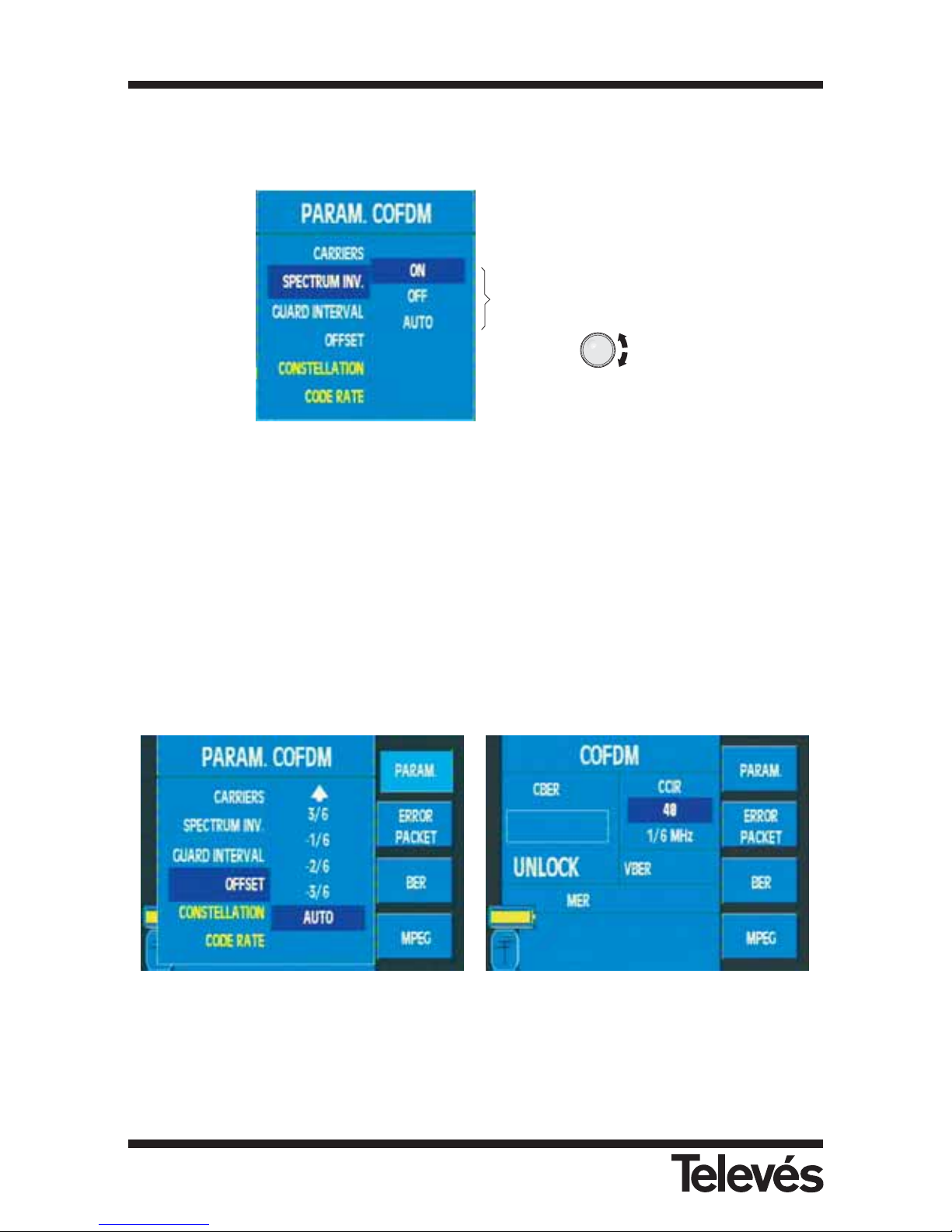
When the rotating knob is pressed, the window that corresponds to the selected parameter
opens:
Figure 76.- COFDM parameter options
In the Offset option, if the COFDM channel has a frequency deviation, you can apply an offset
(0, 1/6, 2/6, 3/6, -1/6, -2/6, -3/6, Auto) to correct this deviation.
This will only be valid in channel mode and you can select it by choosing the current COFDM
channel.
The selection can be manual or automatic. When you select the automatic option, the
equipment will automatically detect the offset. This may take a few moments as a scan is
carried out for with all the possible offsets.
Figure 77.- Determining a COFDM offset
The parameter window will display the information on the constellation being used in each
carrier and the code rate in yellow.
Possible options that can be
selected with the Spectrum
Inversion parameter using
the rotating knob
Multimetter FSM 500 Ref. 5903
66
Page 67
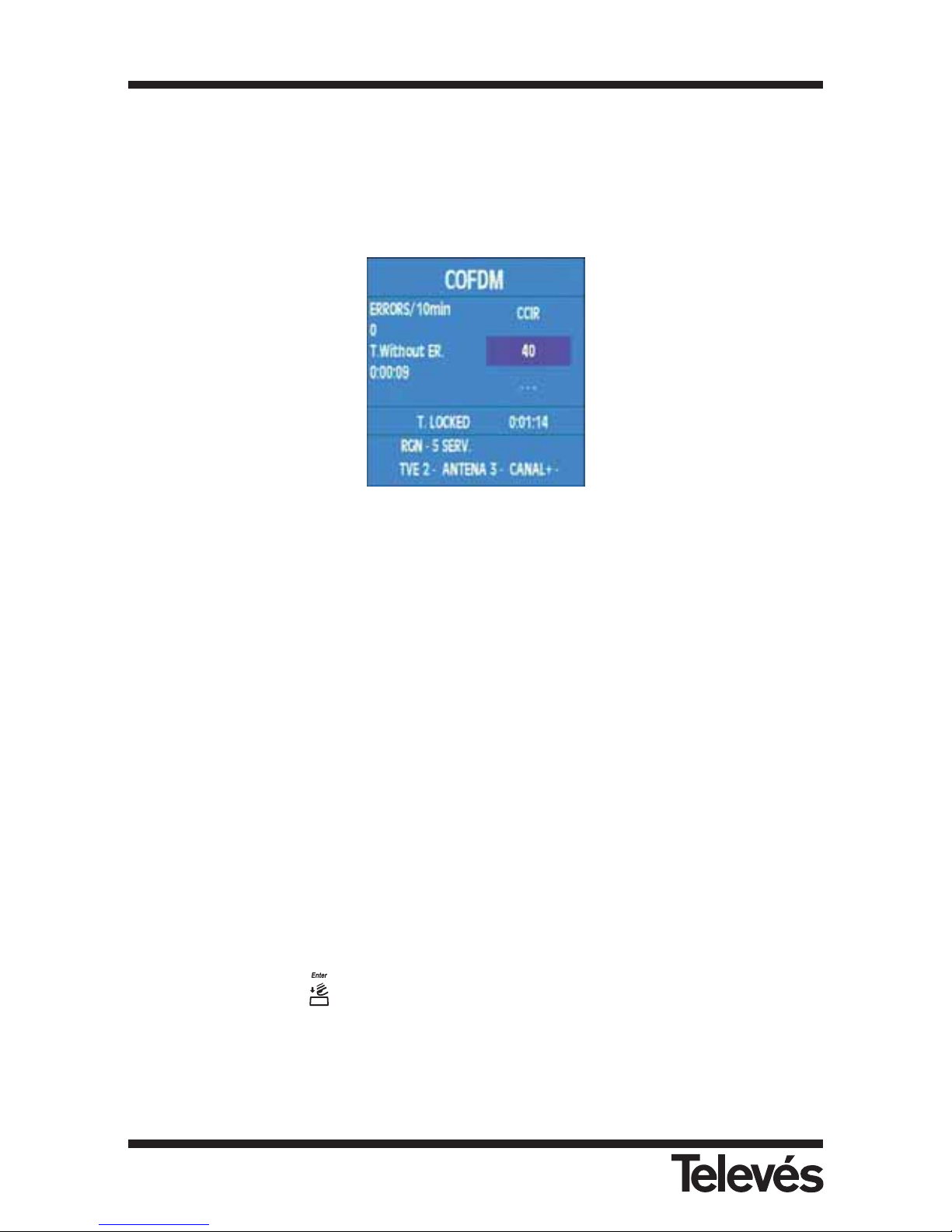
3.3.3.2.2.4.1.2.- Error packets
When this function is selected, a window opens which displays the following information: the
maximum number of error packets in a 10 minuted interval, the time that has elapsed since the
last error and the time that the equipment has been locked onto the signal for (without a visible
error on the screen). The window that displays this information is the following:
Figure 78.- Error packets
This function is very useful when identifying problems in an installation, which a certain
measurement at a specific time has not been able to detect.
3.3.3.2.2.4.1.3.- BER
When this function is selected, the error packet window closes and the BER measurement
window appears again.
3.3.3.2.2.4.1.4.- MPEG
By pressing on this option, the MPEG decoding is enabled. The message "STARTING MPEG"
will appear and then the search for the available services will begin, with the message
"SEARCHING SERV.".
If we do not dispose of a COFDM signal, the screen will display “UNLOCK”.
By using the rotating knob we can access the list of channel services. When the desired channel
has been found, press to confirm the choice. Now it is necessary to select the desired
audio.
Multimetter FSM 500 Ref. 5903
67
Page 68
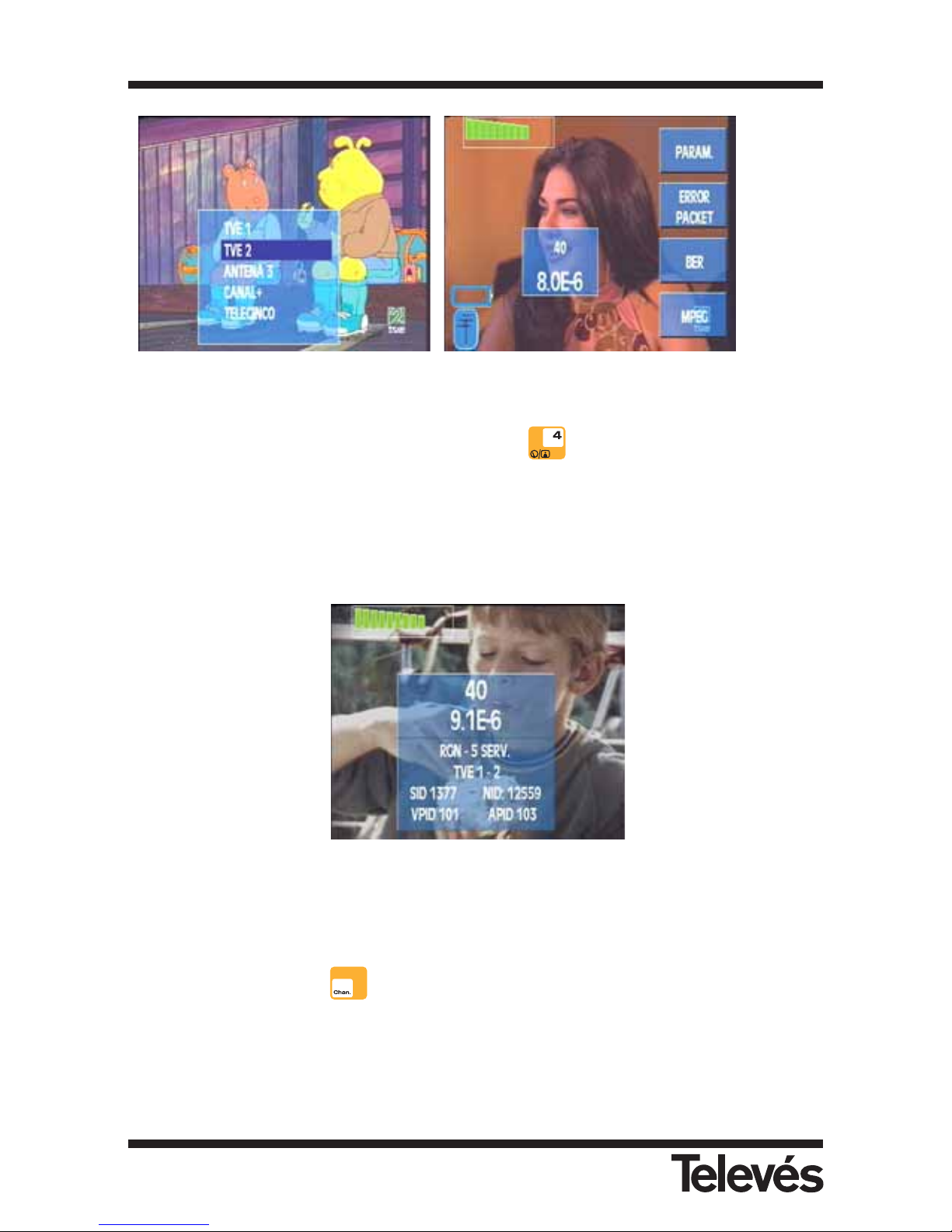
Figura 79.- MPEG decoding of a COFDM channel
In this option there is an extended window (short cut ) which displays some information
about the tuned channel: the number of services, the selected service (if it is a scrambled
channel, # will appear beside the name), the SID network identifier, VPID (for the audio
channels the value 0 will appear) and the APID.
The network identifier is also displayed (NID), if this value is unknown, then this number will be
displayed in hexadecimal format.
Figura 80.- Channel information
Note: It is possible to change service at any moment by using the rotating knob.
To change channnel press .
3.3.3.2.2.4.1.1
3.3.3.2.2.4.1.2
3.3.3.2.2.4.1.3
3.3.3.2.2.4.1.4
Multimetter FSM 500 Ref. 5903
68
Page 69
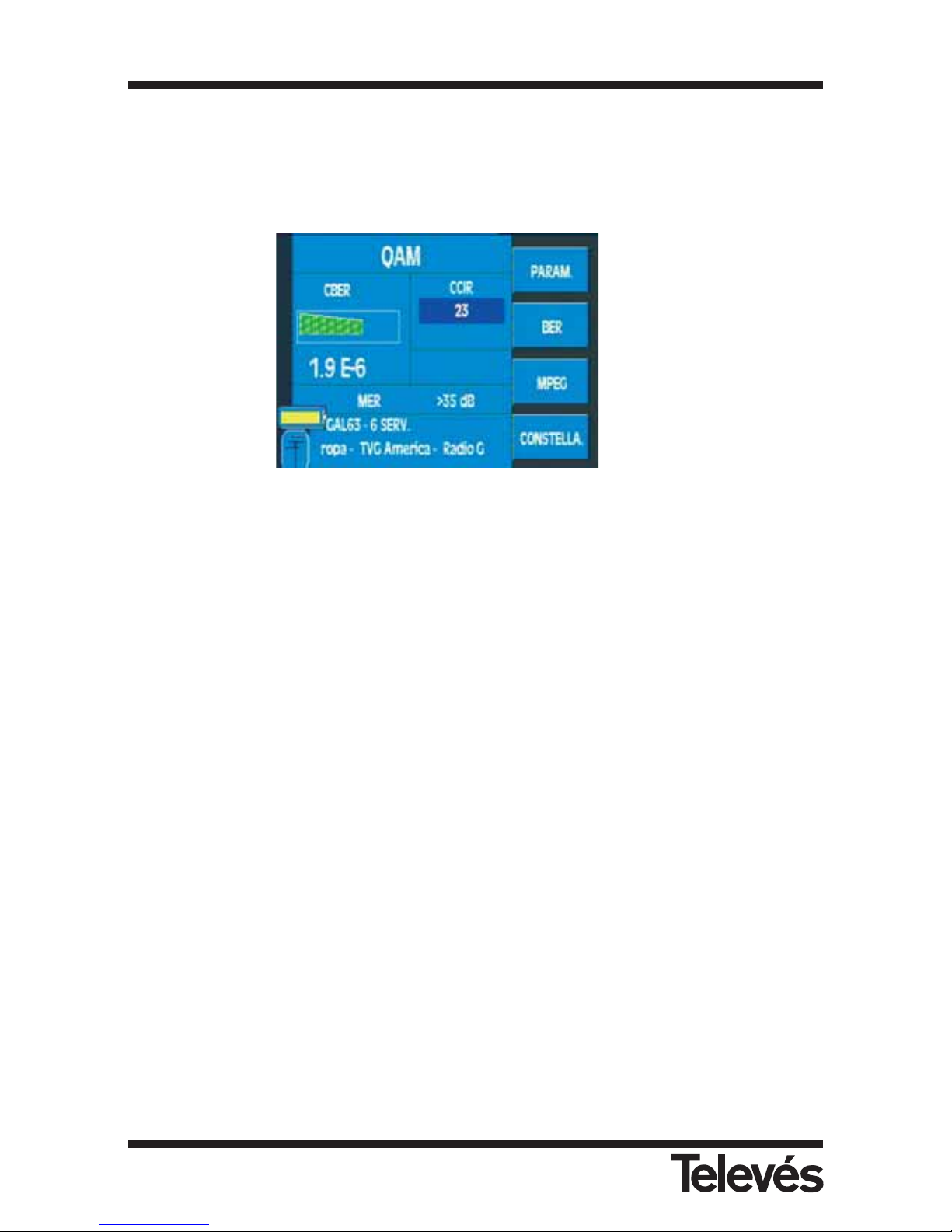
3.3.3.2.2.4.2.- QAM (only terrestrial band)
When this function is selected, the equipment measures the BER of a digital signal with QAM
modulation. The information window is identical to the previous one. The submenu for this
function is the following:
Figure 81.- QAM measurements
It is very important to take into account that the CBER parameter determines quite clearly
the quality of the installation. This is why we have simplified the interpretation of this
parameter with these colours. The VBER is a parameter that has practically only got two
states, either very good or very bad, which makes it difficult to use to appropriately
evaluate the installation. This is why we recommend using the CBER status to assess the
quality of the installation (it should be a small as possible).
If there is not MER option, the MER text "Option" will appear onscreen.
3.3.3.2.2.4.2.1.- Parameters
The parameters that can be selected for a QAM signal are: Symbol rate (6875, 6111, 5156,
4583, 5893, 5238, 6900, OTHER (6875)), Constellation (4QAM, 16QAM, 32QAM, 64QAM,
128QAM, 256QAM, OTHER), and Spectrum Inversion (ON, OFF, AUTO). These parameters are
selected in exactly the same way as those with COFDM modulation.
If we are in constellation mode, as well as the previous parameters, we will also dispose of the
ZOOM parameter to select the square we want to see of the constellation.
3.3.3.2.2.4.2.1
3.3.3.2.2.4.2.2
3.3.3.2.2.4.2.3
3.3.3.2.2.4.2.4
3.3.3.2.2.4.2.1
3.3.3.2.2.4.2.3
3.3.3.2.2.4.2.4
Multimetter FSM 500 Ref. 5903
69
Page 70
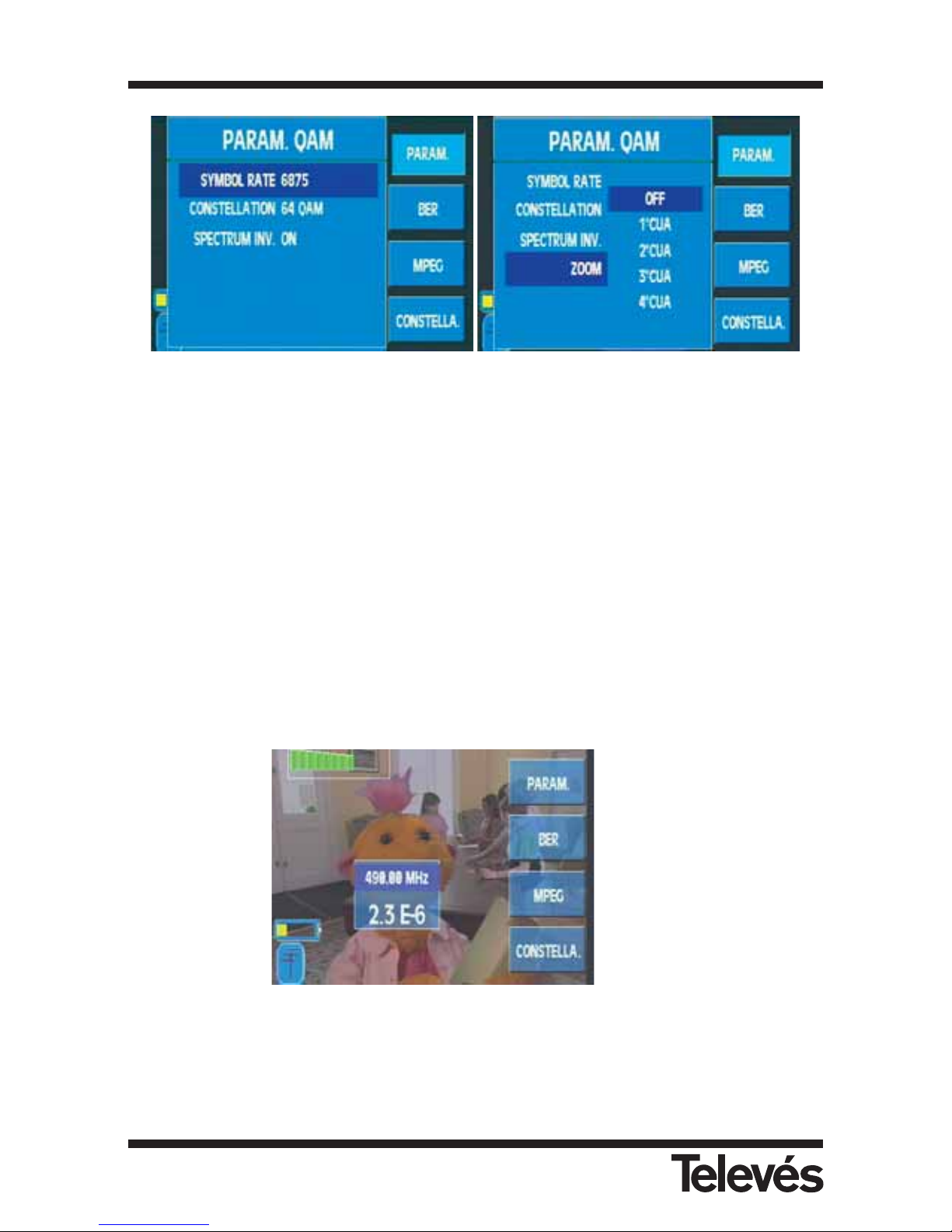
BER parameters Constellation parameters
Figura 82.- Parameter options
3.3.3.2.2.4.2.2.- BER
When this function is selected, the parameters window closes and the BER measurement
window appears again.
3.3.3.2.2.4.2.3.- MPEG
By enabling this option, the user enters the MPEG decoding mode in a QAM channel. The
operation mode is similar to MPEG of COFDM (see 3.3.3.2.2.4.1.4).
Figura 83.- MPEG decoding of a QAM channel
3.3.3.2.2.4.2.1
3.3.3.2.2.4.2.2
3.3.3.2.2.4.2.3
3.3.3.2.2.4.2.4
Multimetter FSM 500 Ref. 5903
70
Page 71
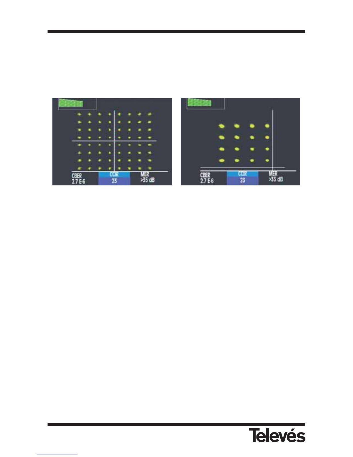
3.3.3.2.2.4.2.4.- Constellation (OPTION 1)
This function can represent the QAM constellation. The screen can also display additional
information in order to assess the signal quality (CBER and MER).
By accessing "PARAMETERS" we can amplify any of the quadrants.
If we do not dispose of the Constellation function, this function will appear with a shadow.
Constellation image Zoom 1º quadrant
Figura 84.- Representation of the QAM constellation
Multimetter FSM 500 Ref. 5903
71
Page 72
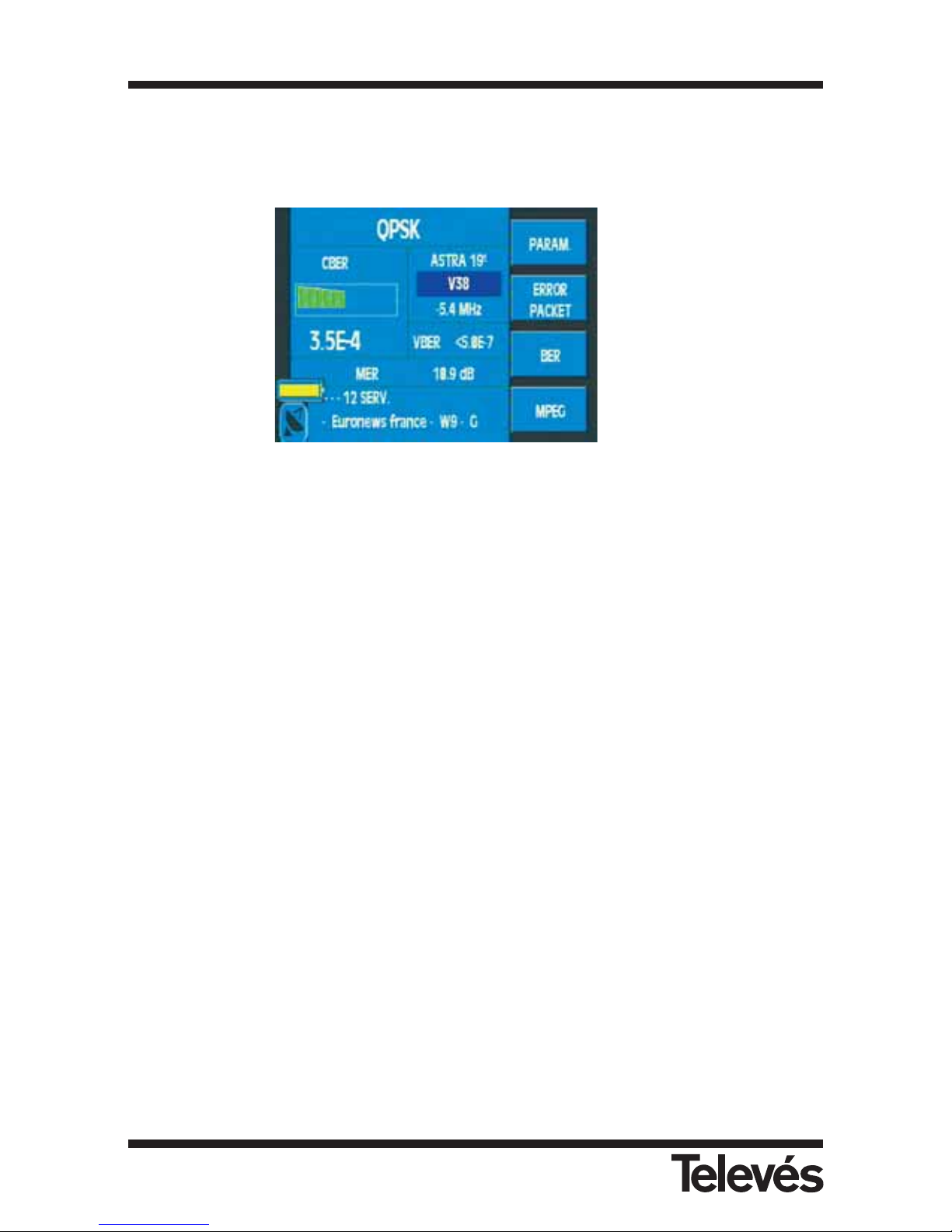
3.3.3.2.2.4.3.- QPSK (only the satellite band)
This function measures the BER of a digital signal with QPSK modulation. The information
window is exactly the same as the window for the QAM and COFDM modulations. The
submenu is the following:
Figure 85.- QPSK measurements
If you do not dispose of the MER option, onscreen you will see the MER text "Option”.
3.3.3.2.2.4.3.1.- Parameters
The parameters that can be selected for a QPSK signal are the following: Symbol Rate (27500,
24500, 22000, 15000, OTHER), Code (Auto, 2/3, 3/4, 5/6, 7/8, 1/2), and Spectrum Inversion
(ON, OFF, AUTO). The parameters are selected in the same way as with the previous functions.
3.3.3.2.2.4.3.2.- Error packets
The window that opens when this function is selected and the information that is displayed is
exactly the same as with the COFDM modulation.
This function is very useful when identifying problems in an installation, which a certain
measurement at a specific time has not been able to detect.
3.3.3.2.2.4.3.3.- BER
When this function is selected, the error packet window closes and the BER measurement
window appears again.
It is very important to take into account that the CBER parameter determines quite clearly
the quality of the installation. This is why we have simplified the interpretation of this
parameter with these colours. The VBER is a parameter that has practically only got two
states, either very good or very bad, which makes it difficult to use to appropriately
evaluate the installation. This is why we recommend using the CBER status to assess the
quality of the installation (it should be a small as possible).
3.3.3.2.2.4.3.4.- MPEG
With this option, the MPEG mode of a QPSK channel is enabled. The functions in the same way
as in QAM and COFDM.
3.3.3.2.2.4.3.1
3.3.3.2.2.4.3.2
3.3.3.2.2.4.3.3
3.3.3.2.2.4.3.4
Multimetter FSM 500 Ref. 5903
72
Page 73
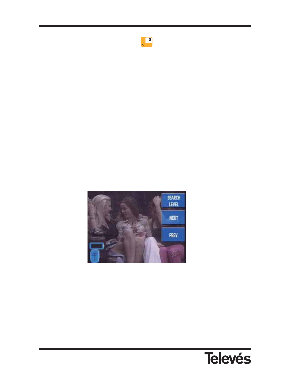
3.3.3.3.- Channel search (short cut button )
The FSM 500 features an automatic channel search function. The search is carried out
according to a certain threshold as defined by the user in the Search Level.
It also depends on whether the meter is in channel tuning mode or frequency tuning mode.
If the meter is in channel tuning mode, it is carried out according to the selected channel plan.
The equipment automatically searches for the corresponding channel according to the plan and
if the video carrier level is higher than the search level, then the channel is tuned in. If it is not,
it progresses onto the next channel, and so on until it finds a channel with a video carrier level
higher than the threshold defined by the user.
If however, the meter is in frequency tuning mode, the selected channel plan is not taken into
account. Instead the meter uses the frequencies in the spectrum. When the equipment finds a
frequency that is higher than the established threshold, it carries out a selective search within
a specific margin of frequencies to find the maximum and then it tunes that frequency as the
video carrier. If, once a channel has been tuned in this way, the equipment switches to channel
tuning mode, the tuned channel may not be in the selected channel plan, so the equipment will
tune the nearest channel within this plan.
The automatic channel search can be a very useful function when checking an
installation. Thanks to this function, it is possible to see the channels automatically and
in sequence, without having saved the channels previously or even without knowing
which channels are present.
This menu has the following submenus:
Figure 86.- Channel search options
3.3.3.3.1
3.3.3.3.2
3.3.3.3.3
Multimetter FSM 500 Ref. 5903
73
Page 74
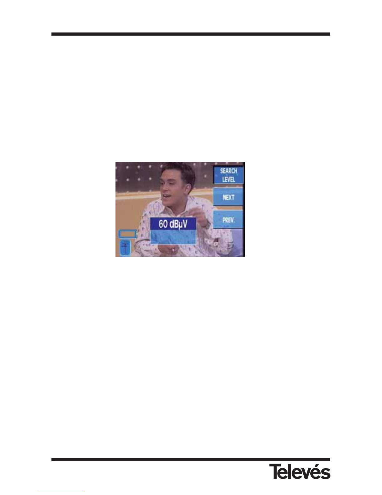
3.3.3.3.1.- Search level
This parameter defines the threshold that the video carrier must surpass for the equipment to
tune a specific channel when carrying out an automatic search. When this function is selected,
a window opens onscreen, and the value of the search level can be modified using the rotating
knob. The possible values range from 40 and 120 dBµV.
It is best to program a search value that is close to the signal level that we are using in the
equipment, in other words, if we want to scan through the channels of a headend quickly using
this function, if the headend output is at approximately 115 dbµV, the correct way to proceed
is to program search values that are higher than 110 dbµV.
If we enter values that are very low compared to the level that we are using (for example
60 dbµV in this case), we are helping to saturate the equipment and using this function
incorrectly.
Figure 87.- Search level
3.3.3.3.2.- Next
This tunes the channel that has a video carrier level that surpasses the search level and that is
immediately next in frequency to the tuned channel.
3.3.3.3.3.- Previous
This tunes the channel that has a video carrier level that surpasses the search level and that is
immediately before in frequency to the tuned channel.
3.3.3.3.1
3.3.3.3.2
3.3.3.3.3
Multimetter FSM 500 Ref. 5903
74
Page 75
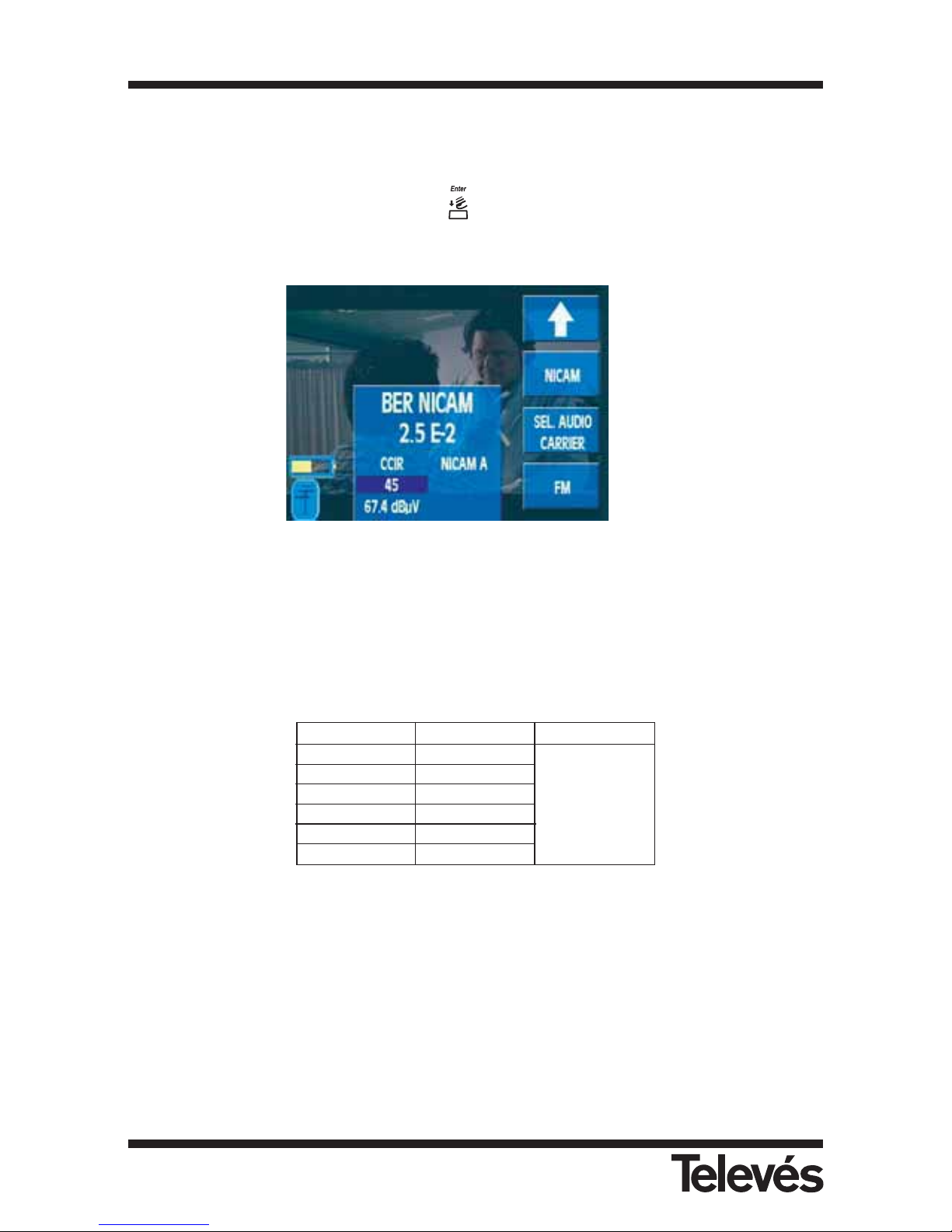
3.3.3.4.- Nicam (OPTION 1)
This function activates the NICAM mode. This mode presents the BER NICAM measurement,
and it also disposes of the audio selection. To select the audio, we must choose the desired
channel using the rotating knob and press (OFF, Nicam A, Nicam B).
If we do not dispose of the NICAM function, this will appear with a shadow.
Figura 88.- NICAM mode activated
3.3.3.5.- Selecting the Audio Carrier
The options that appear here depend on the band and on the colour standard that has been
selected:
To select the option that you want, use the rotating knob.
As well as the frequencies of the audio carrier of each standard, there are two more option in the
window: Freq. and Level. If we select Freq., the audio carrier selection window will close and
another window will open in which the user can select another frequency from “4,00” to “9,00”
using the rotating knob. The Level option activates the audio signal that indicates the carrier
level. This is a tone which changes according to the variations in the signal level, in other words,
the higher the level, the higher the tone (higher frequency).
Band Terrestrial Satellite
PAL B/G 5.50 & 5.74
PAL D/K 6.50 & 6.74
PAL I 6.00
7.02 & 7.20
SECAM B/G 5.50 & 5.74
SECAM L 6.50 6 5.85
SECAM D/K 6.50 & 5.85
3.3.3.4
3.3.3.5
3.3.3.6
Multimetter FSM 500 Ref. 5903
75
Page 76
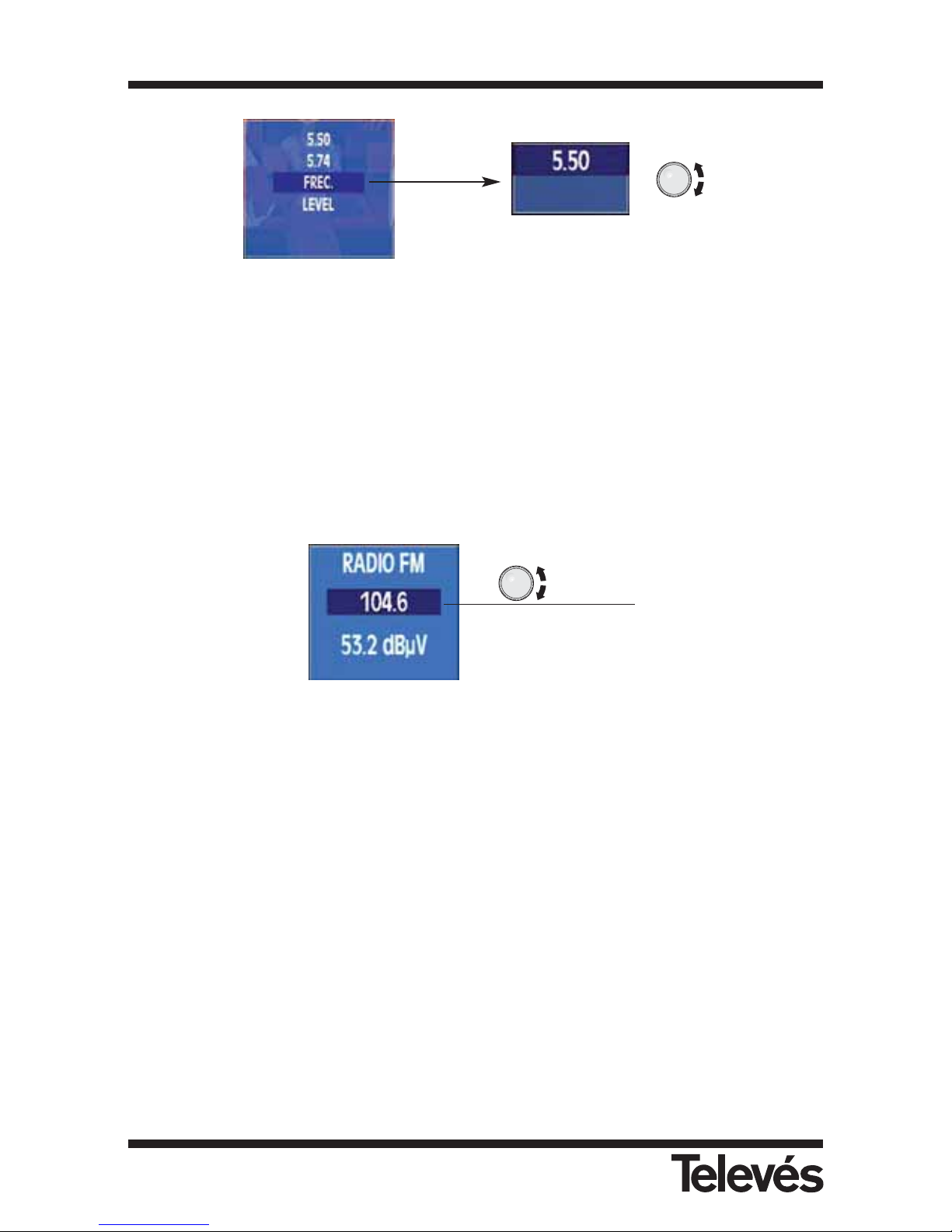
Figure 89.- Audio carrier
To close the window use the Clear button.
3.3.3.6.- FM radio
This function lets you tune the radio in modulated frequency. When this function is selected, a
window opens onscreen where you can see the frequency and the signal level of this frequency.
You can vary the tuned frequency using the rotating knob or entering the value by pressing the
Freq. button. The frequency values are between 88 and 108 Mhz.
Figure 90.- Tuned radio frequency
Tuned FM
frequency
Multimetter FSM 500 Ref. 5903
76
Page 77
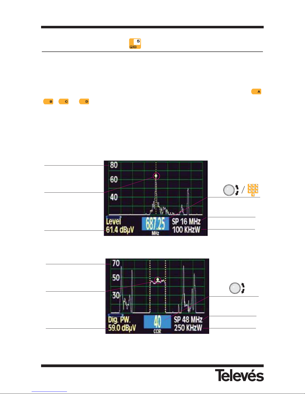
3.3.4.- Spectrum (short cut button )
If this menu is chosen, the meter passes straight to the spectrum analyzer mode. In this mode
you can see the signal spectrum according to the selected span and the tuned frequency. The
lower part of the screen (under the spectrum) is used to display the parameters, measurements,
etc. The menu texts are hidden by default, so that it is easier to see the spectrum properly.
When you need to access the menus, simply press the Clear/Menu button or any of the
, or buttons.
If an analogue measurement is selected, the central part of the spectrum will display a dotted
yellow line, and if a digital measurement is selected, this line does not appear and instead there
are two dotted yellow lines at an equal distance from the spectrum’s central line. The separation
between these lines indicates the channel bandwidth that is selected at that moment.
It is worth noting that, with this meter, you can see any frequency between 5 and 2150 MHz
without interruptions.
Figure 91.- Spectrum analyzer mode. Frequency tuning (analogue channel)
Figure 92.- Spectrum analyzer mode. Channel tuning (digital channel)
Central frequency
level of the spectrum
Reference level
Marker indicating the
central frequency of the
spectrum
Horizontal span
Tuned channel and
channel plan
Resolution filter
Central frequency level
of the spectrum
Reference level
Marker indicating the
central frequency of the
spectrum
Horizontal span
Tuned frequency
Resolution filter
Multimetter FSM 500 Ref. 5903
77
Page 78
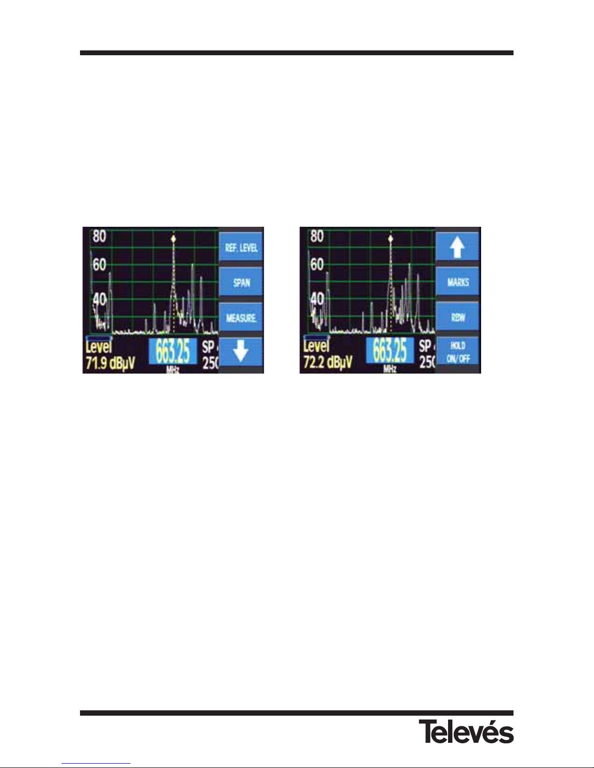
The information about the tuned frequency or channel appears at the bottom of the screen.
If the equipment is in frequency mode, the central frequency of the spectrum will appear. If we
turn the rotating knob, we can change the central frequency, in other words, we move the
spectrum to one side or the other.
If the equipment is in channel tuning mode and in analogue mode, the channel with the tuned
frequency will appear and the spectrum will automatically be centred on the frequency of the
video carrier of this channel. In digital mode, it is positioned in the centre of the channel. If we
turn the rotating knob while in channel mode, we will pass onto the next channel and the
spectrum will go to the next video carrier.
The corresponding submenu is the following:
Figure 93.- Spectrum mode options
3.3.4.1.- Reference Level
This allows you to select the reference level of the spectrum in order to optimize the view of the
spectrum of the signal according to its level. The reference level corresponds to the value of the
upper horizontal line of the spectrum. The possible values are from 60 dBµV to 130 dBµV in
steps of 10 for the terrestrial band, and up to 120 dBµV in the satellite band. When this function
is chosen, the infomation about the level disappears for a moment and reference level options
appear in its place. These are all viewed by turning the rotating knob. When it is pressed, the
value is selected. Then the reference level information disappears and the signal level
information re-appears. Any changes in this value can be seen on the spectrum. This makes it
easier to know which reference level value is the best for the optimum viewing of the spectrum.
3.3.4.4
3.3.4.5
3.3.4.6
3.3.4.1
3.3.4.2
3.3.4.3
Multimetter FSM 500 Ref. 5903
78
Page 79
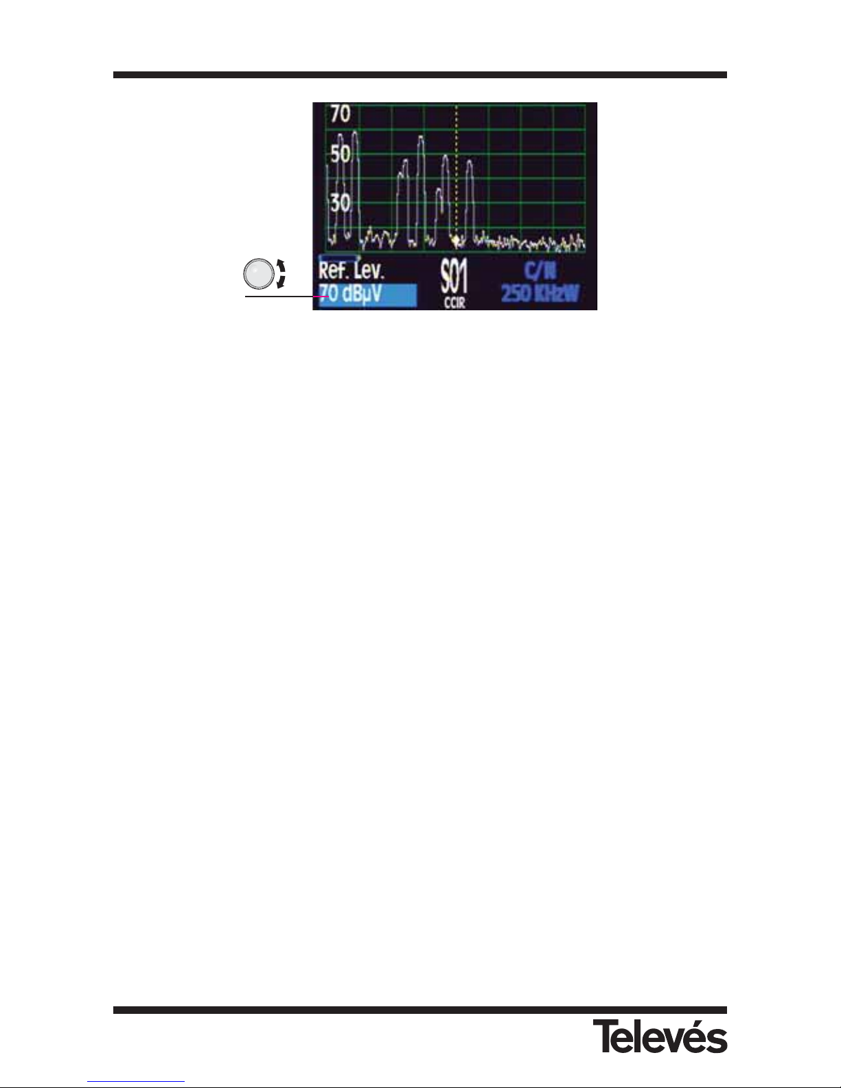
Figure 94.- Reference level
3.3.4.2.- Span
This function lets you vary the range of frequencies that is represented by the spectrum. The
information for the selection of the parameter is displayed on the lower right-hand part of the
screen. As is the case with the Reference Level, the information about the level disappears for
a moment and the information about the span appears. The different options for this parameter
appear as the rotating knob is turned. When the rotating knob is pressed, the value is selected
and the menus disappear from the screen.
The possible values in the FSM 500 meter are:
Terrestrial band: 8, 16, 32, 48, 96, 192, 496 MHz, Full Span
Satellite band: 25, 50, 100, 200, 512 MHz, Full Span
Multimetter FSM 500 Ref. 5903
79
Page 80
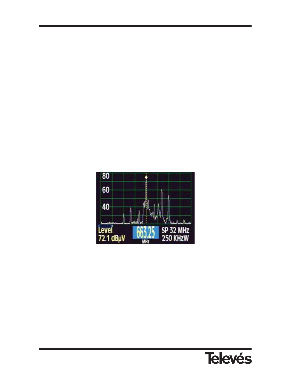
3.3.4.3.- Measurements
The measurements are displayed at the bottom of the screen. While any measurement is being
viewed, the tuned frequency can be varied by turning the rotating knob. This means that the
measurement can be carried out with different frequencies or channels.
When a measurement is selected, the texts automatically disappear from the menus so that
they do not stop the user from seeing the selected measurement and the signal spectrum
properly.
The measurements submenu in spectrum mode is the same as the submenu in TV mode:
3.3.4.3.1.- Analogue
3.3.4.3.1.1.- Level
The measurement of the level is seen on the lower left-hand part of the screen. The frequency
that is used for this measurement is the spectrum’s central frequency (see the mark). If you vary
the tuned frequency with the rotating knob, you will see how the level measurement also
changes.
Figure 95.- Signal level
3.3.4.3.1.2.- V/A
The measurement of the audio carrier level/ video carrier level ratio is displayed on the lower
right-hand part of the screen. The spectrum’s central frequency is taken as the carrier
frequency, and the audio carrier level is measured in the frequency that is indicated in the audio
carrier selection (this function is in TV Mode - Sel. Audio Carrier).
On the left-hand side, you can see the measurement of the central frequency level.
Multimetter FSM 500 Ref. 5903
80
Page 81
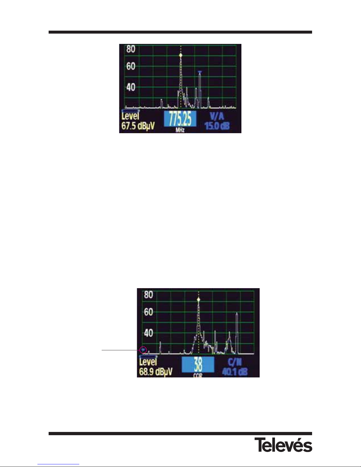
Figure 96.- A/V carrier ratio
3.3.4.3.1.3.- Automatic C/N
The C/N measurement is also displayed on the lower part of the screen.
As is the case with the V/A measurement, the carrier level is measured in the spectrum’s central
frequency
The equipment selects the frequency that is used to measure the noise.
3.3.4.3.1.4.- Referenced C/N
In the case of the referenced C/N, the frequency that is used to measure the noise must be
selected by the user. When using this function, a second blue marker appears on the spectrum,
indicating the frequency that is being used to measure the noise.
Figure 97.- Referenced C/N
To access the submenu of this function where the frequency at which the noise level is
measured and the channel bandwidth are selected, you must press the Clear/Menu button.
The menus will appear again and we can select these parameters. The options for these
Marker
indicating
the noise
frequency
Multimetter FSM 500 Ref. 5903
81
Page 82
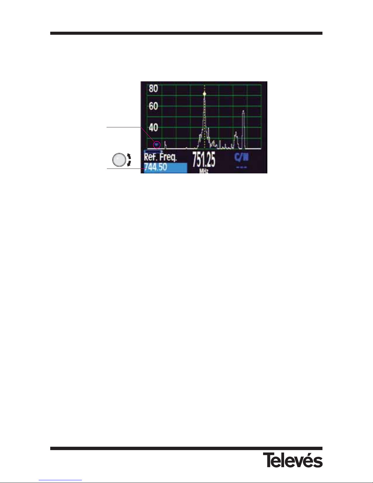
parameters are displayed on the lower left-hand part of the screen; the level measurement
disappears for a moment, and once the desired value has been selected (by pressing the
rotating knob), the level measurement re-appears:
Figure 98.- Noise measurement
3.3.4.3.1.4.1.- Reference frequency
This function lets you vary the frequency that will be used to measure the noise. The rotating
knob moves the blue marker so that it passes through all of the frequencies that are visible
onscreen. Once the marker is over the desired frequency, press the rotating knob. This will now
be used as a reference to measure the C/N.
It is important to point out that the noise frequency marker (blue) can only be
moved through the frequencies that can be seen onscreen. Therefore, if the user
wants to select another frequency that is not in this range, it will be necessary to
select a greater horizontal span.
3.3.4.3.1.4.2.-Channel bandwidth
To take a correct measurement of the C/N, the user must select the channel bandwidth, as this
is the parameter that will be used to correct the value of the noise level that is measured using
the reference frequency in order to apply it to the whole channel bandwidth.
Noise
frequency
marker
Noise
frequency
Multimetter FSM 500 Ref. 5903
82
Page 83
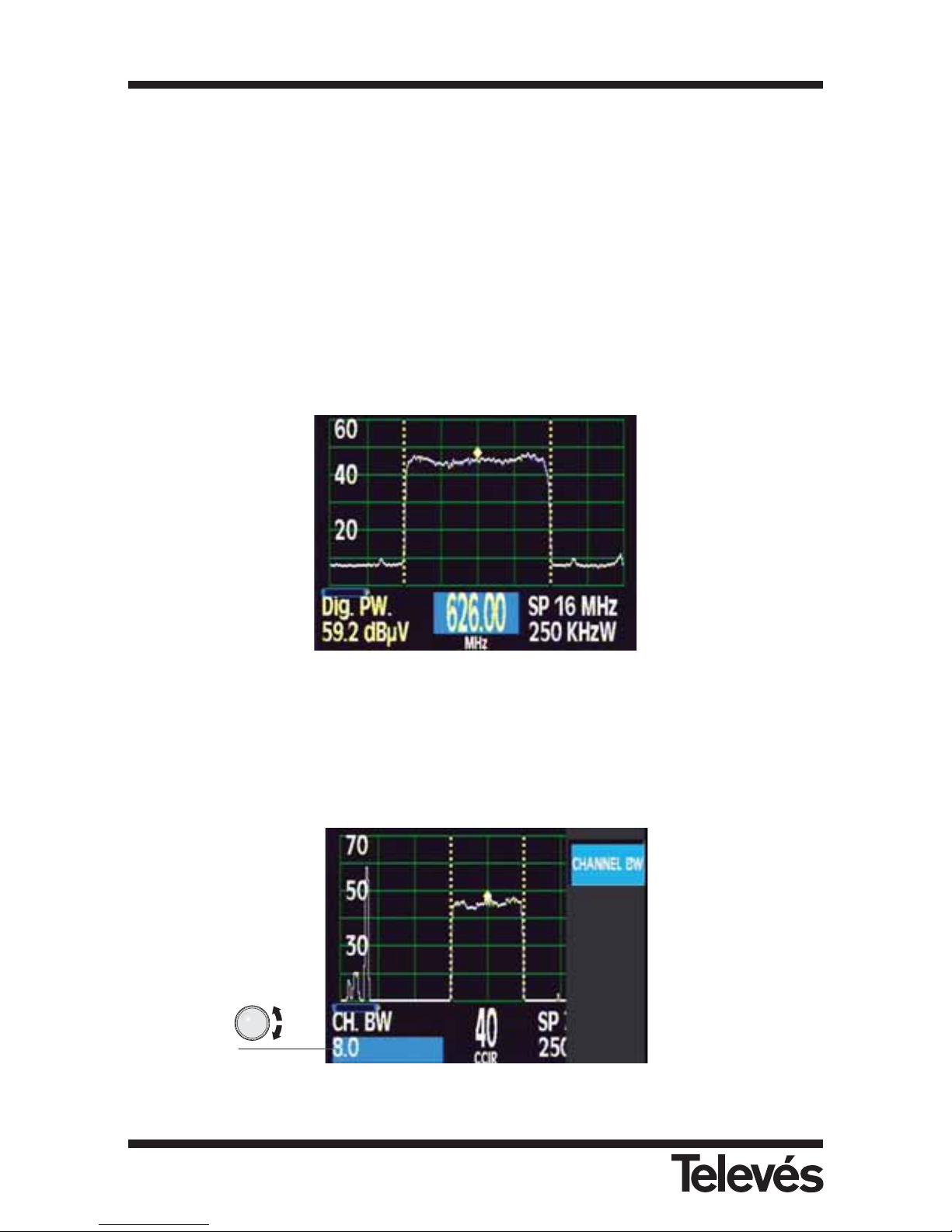
3.3.4.3.2.- Digital
3.3.4.3.2.1.- Channel power
The channel power is displayed on the lower left-hand part of the screen. For this measurement,
the meter takes the spectrum’s central frequency (the tuned frequency) to be the central
frequency of the digital channel. This is important if the channel power is to be measured
correctly. To carry out this measurement it is also very important to select the channel bandwidth.
The equipment carries out the calculation of the digital power automatically (lower lefthand part of the screen). When choosing the reference level, it is important for the digital
power of the channel not to surpass this reference, as the equipment would become
saturated and the results may not be correct.
See that the digital power is clearly higher than the analogue level that the equipment indicates.
The submenu allows us to select the channel bandwidth.
Figure 99.- Power of a digital channel
3.3.4.3.2.1.1.- Channel bandwidth
When this parameter is being selected, the information about the channel power measurement
disappears and the channel bandwidth appears in its place. This can be modified using the
rotating knob. To select the desired value, press the rotating knob. The bandwidth information
will disappear and the power measurement information will appear again.
Figure 100.- Bandwidth of the digital channel
3.3.4.3.2.1.1
Multimetter FSM 500 Ref. 5903
83
Page 84

3.3.4.3.2.2.- Automatic C/N
The automatic C/N measurement for digital channels is the same as for analogue channels. This
function has the following submenu:
3.3.4.3.2.2.1.- Channel bandwidth
When this parameter is selected, the information about the channel power measurement
disappears and the channel bandwidth appears in its place. This can be modified using the
rotating knob. To select the desired value, press the rotating knob. The bandwidth information
will disappear and the power measurement information will appear again.
3.3.4.3.2.3.- Referenced C/N
The measurement of the C/N of digital channels is also displayed on the lower left-hand part of
the screen. The user must select the frequency value that will be used to carry out the noise
measurement and the channel bandwidth. This function has the following submenu:
3.3.4.3.2.3.1.- Reference frequency
This function lets you vary the frequency that will be used to measure the noise. Use the rotating
knob to move the blue marker through the range of frequencies that are visible onscreen. Once
the marker is signalling the desired frequency, press the rotating knob. The C/N measurement
will be carried out using this frequency as the noise reference.
3.3.4.3.2.3.2.- Channel bandwidth
When this parameter is selected, the information about the channel power measurement
disappears and the channel bandwidth appears in its place. This can be modified using the
rotating knob. To select the desired value, press the rotating knob. The bandwidth information
will disappear and the power measurement information will appear again.
Multimetter FSM 500 Ref. 5903
84
Page 85
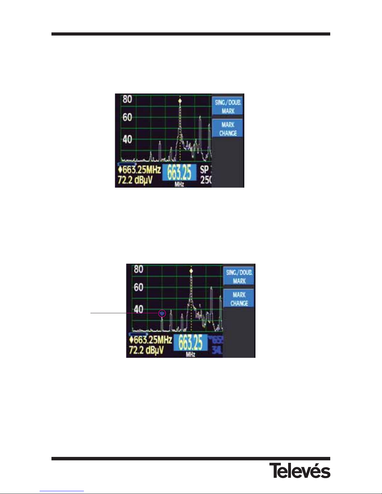
3.3.4.4. Markers
The FSM 500 has the possibility of using two markers on the screen. Using the functions of this
submenu, you can move them through the whole spectrum to carry out the level measurements
in the two marked frequencies.
The submenu is:
Figure 101.- Marker options
3.3.4.4.1.- Simple/Double marker
By default, when you access this submenu, there will only be one yellow marker on the
spectrum. If you select this function, another marker will appear (blue).
Figure 102.- Second marker
Simply press this option again to make the blue marker disappear.
3.3.4.4.2.- Changing markers
This function lets you move the markers around the spectrum, thereby varying the frequency of
each one.
If you press this function, you select the blue marker:
3.3.4.4.1
3.3.4.4.2
Second
marker
enabled
3.3.4.4.1
3.3.4.4.2
Multimetter FSM 500 Ref. 5903
85
Page 86
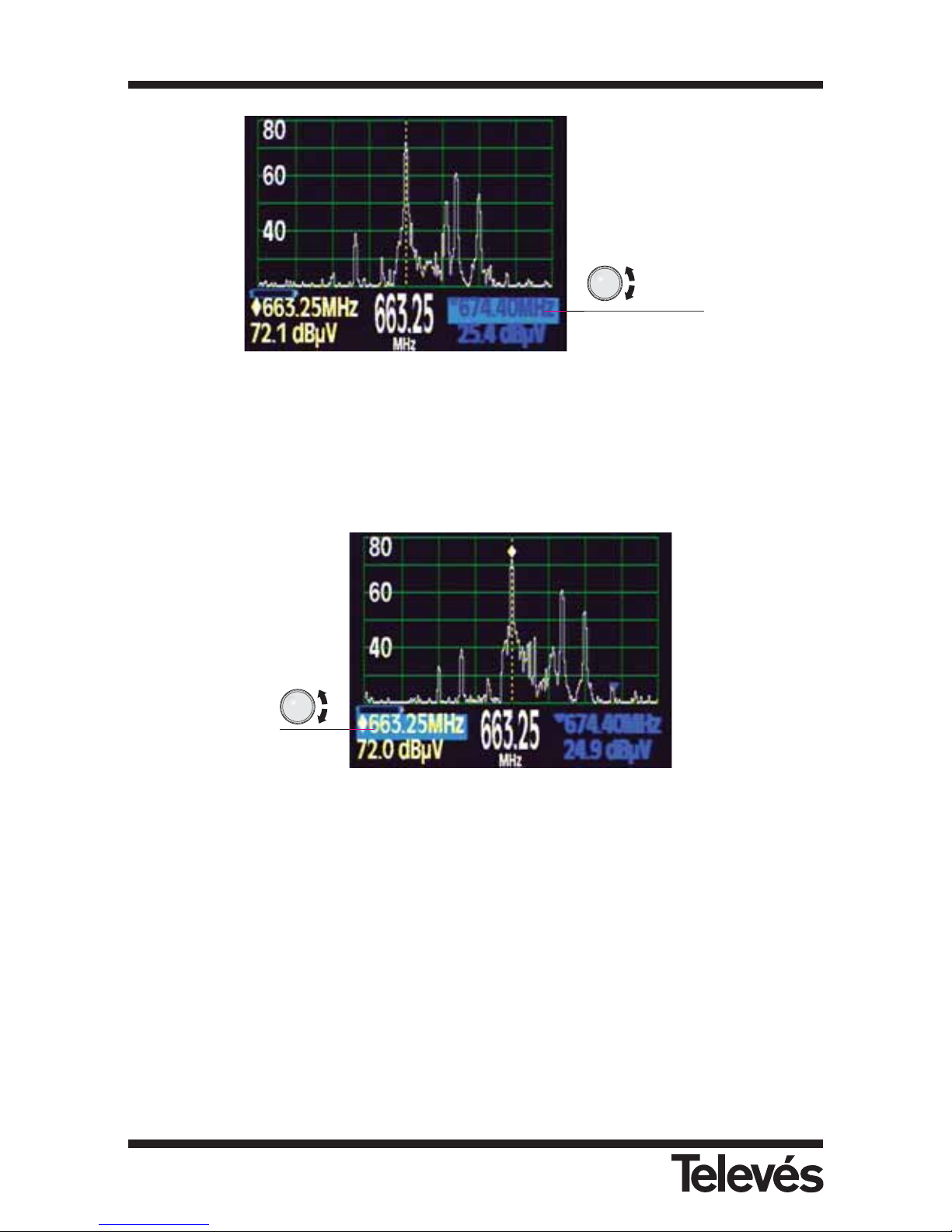
Figure 103.- Second marker enabled
When the marker is selected, you can move it along the spectrum that is visible onscreen (this
will depend on the selected span) by using the rotating knob.
If this option is pressed again, the yellow marker will be selected, and you can move this in the same
way
Figure 104.- First marker enabled
3.3.4.5.- RBW
The FSM 500 uses the four I.F. filters automatically, depending on the selected SPAN. Using this
function you can modify the bandwidth of the resolution filter. The possible values are: 100 KHz, 250
KHz, 1 MHz and 3 MHz
The selection you have made will be kept while the horizontal span does not change, as when this
parameter changes the equipment selects the resolution filter that is appropriate for the new span.
Once the new span has been selected, if you wish to use a different filter, you need to use this
function again.
It is necessary to note that if an inappropriate resolution filter bandwidth is selected, the
measurement carried out by the equipment may not be correct. For example, if you are using a large
horizontal span and you select a narrow measurement filter, the measurement that is carried out on
the signal will not be correct. Therefore, it is advisable to use the resolution filter that is automatically
selected by the equipment when the horizontal span varies.
First
marker
selected
Second
marker
selected
Multimetter FSM 500 Ref. 5903
86
Page 87
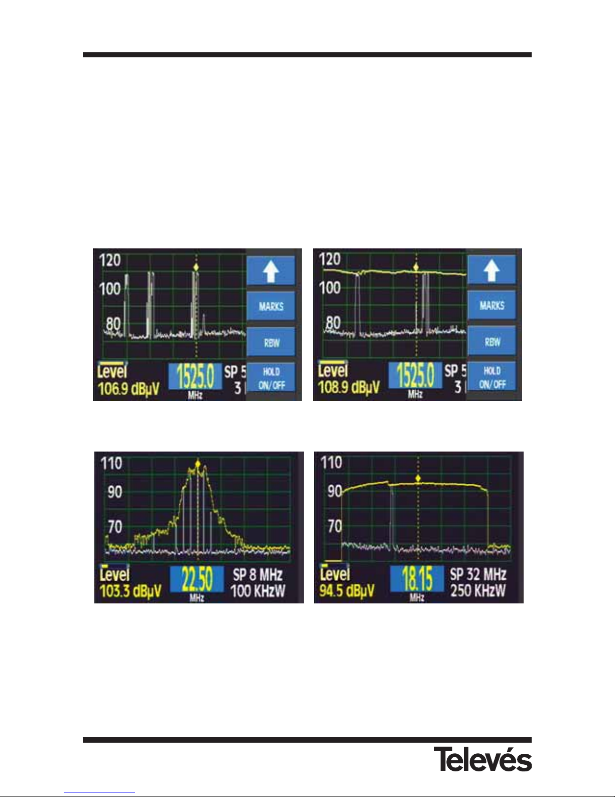
3.3.4.6.- Hold (On/Off)
This function represents pulse signals or signals that change quickly.
When you select it, a yellow graph will appear which indicates the maximum signal levels at
each point.
When you select it again, this graph disappears.
In both cases, the white graph will continue to represent the instantaneous signal.
This function cannot be used to carry out a measurement of the digital power.
When any of the parameters of the spectrum are modified (reference level, RBW, Span) the
graph that represents the maximum levels will disappear and it will begin to discover the
maximum levels again taking into account the new conditions that have been selected.
(Example with an IF simulator - ref. 4008)
(Ex. Televés Integra carriers - ref. 7622) (Ex. Return Channel Generator - ref. 7637)
Figure 105.- Selection of the maximum levels (ON/OFF)
Multimetter FSM 500 Ref. 5903
87
Page 88

3.4.- ERROR WARNINGS
When the equipment detects an error in any of the modules or components, it warns the user
through a series of messages as can be seen below:
· NO BAT. :
This message appears when the equipment is switched on and no batteries are detected.
The equipment operates correctly while connected to the mains.
The same message appears when the user wishes to charge the batteries and there are no
batteries connected to the equipment.
· WRONG BATT:
This message appears when the equipment is switched on and when the batteries that are
being used are not the same as the ones that come with the equipment from the factory or
when the position of the configuration microswitches of the battery (side of the equipment)
are not in the correct position. When the equipment displays this error message, it is
impossible to charge the batteries (see section 3.3.2.6.2).
· FULL BAT :
This message will appear when the user tries to charge a battery that is already charged.
· EXCES TEMP:
The equipment continuously monitors the temperature. When it is too high, this message
flashes onscreen. If the temperature does not go down, the equipment shuts down
automatically. If the temperature goes down, the message disappears.
If this message appears, it is advisable to improve the conditions in temperature. The user
can carry out various modifications, for example, place the equipment in a more ventilated
area, take away any objects that may be blocking its ventilation, stop charging the batteries
(button
) if the equipment is in use.
If this warning message does not disappear, it is advisable to switch the equipment off while
keeping the external power supply connected, to facilitate the elimination of the internal
heat.
· ERROR XXXX:
When the equipment is switched on, it checks all of its modules. When it detects an error in
any of these, an ERROR message will appear followed by a code. If this happens, please
contact your local Televés distributor, informing him/her of this error code.
· ERR CHARGE:
When the DC adapter is connected to the equipment, this checks the current in the external
powering connector (31). If the equipment detects an erronious current, it warns the user via
an error message which flashes onscreen. The Ext. Supply LED will also flash.
· Vext.:
This error message appears when the voltage of the external units is selected and when the
equipment detects a different current in the “F” connector than that selected by the user.
Multimetter FSM 500 Ref. 5903
88
Page 89

· NO POWERING:
This message appears when the user tries to charge the batteries and there is no external
powering.
· SHORT CIRCUIT:
This message appears when the equipment detects a shortcircuit in the “F” connector. The
equipment will also emit a noise. The powering will be cut off and it will try again every 3
seconds.
· EXCES CURRENT:
This message appears when the power consumption surpasses the maximum allowed. The
powering is cut off and it will try again every 3 seconds.
· No DiSEqC. Vdc off: This message appears when one of the DiSEqC inputs is selected
when the powering of external units is switched off.
Multimetter FSM 500 Ref. 5903
89
Page 90
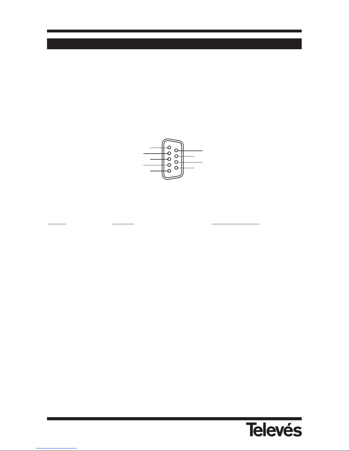
4.- DESCRIPTION OF THE INPUTS AND OUTPUTS
4.1.- RF INPUT
The RF input is through the connector (30) on the side panel. The maximum signal level should
never exceed 130 dBµV. This connector is easily replaced when this becomes necessary.
4.2.- RS-232C SERIAL PORT
The FSM 500 features an RS-232C serial port for exchanging data with a PC or any other
device. The signals in this connector are described below:
Figure 106.- RS 232 connector
PIN Nº
SIGNAL SPECIFICATIONS
1 - (not connected)
2 Data Request (RxD)
3 Data Transmit (TxD)
4 - (not connected)
5 Ground (GND)
6 - (not connected)
7 - (not connected)
8 - (not connected)
9 - (not connected)
1
2
3
4
5
6
7
8
9
Multimetter FSM 500 Ref. 5903
90
Page 91
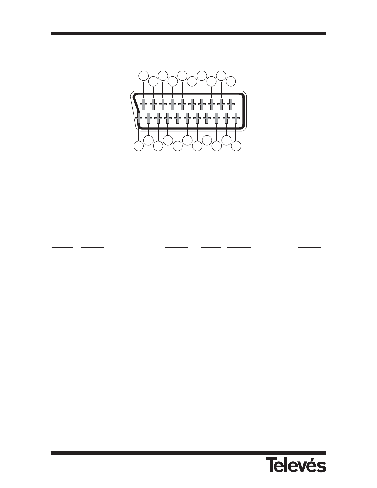
4.3.- SCART (DIN EN 50049)
Figure 107.- SCART
Also known as a PERITEL connector (in compliance with standard NF-C92250).
The signals in this connector are as follows:
PIN Nº
SIGNAL SPECS. PIN Nº SIGNAL SPECS.
1 Right ch. audio output 12 Digital bus interface (N/C)
2 Right ch. audio input 13 Red grounding (R)
3 Left ch. output output 14 Digital bus reserved (N/C)
4 Audio grounding 15 Red output (R)
5 Blue grounding (B) 16 Blanked signal (N/C)
6 Left ch. audio input 17 Composite video gnd
7 Blue output (B) 18 Blanked return (N/C)
8 Switching voltage 19 Composite video output
9 Green grounding (G) 20 Video input
10 Digital bus interface (N/C) 21 Connector shield grounding
11 Green output (G)
201816
14
12
10
8
6
4
2
1
3
5
7
9
1
13
15
17
19
21
Multimetter FSM 500 Ref. 5903
91
Page 92
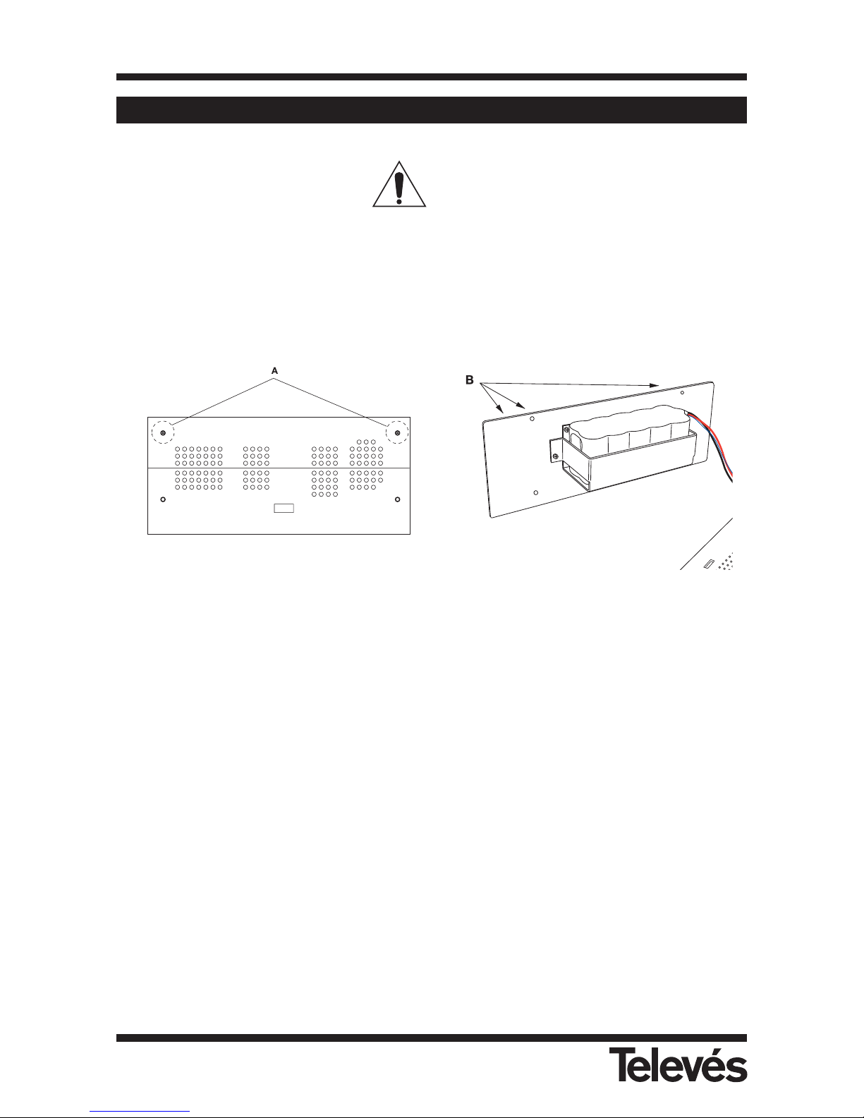
5.- MAINTENANCE
5.1.- REPLACING THE BATTERY
The battery should be replaced when its capacity (fully-charged) has diminished considerably.
To ensure that the equipment operates correctly, it should be provided by Televés, as it should
incorporate the appropriate protective features.
To replace the battery, follow the procedure explained below:
- Switch the equipment off and disconnect the external power supply
- Remove the protective holster, if in place.
- Remove the 5 screws (A) that secure the top of the meter and take the top off.
- The battery compartment is located in the rear panel of the equipment. Remove the 4
fixing screws (B) as shown in the previous figure. Remove the rear panel.
- In order to remove the battery completely, you need to disconnect it from the connector
that is located inside the meter. Follow the cables from the battery to find this connector.
- For the protective features of the batteries to work properly, place the new batteries in the
same position as the old batteries.
- Connect the terminals to the new batteries. Remember to watch out for the position of the
connector.
- Replace the panel and fix it securely using the 4 screws (B). Do the same with the top and
the remaining screws (A). Finally replace the protective holster.
- If you also changed the battery model, update this in the microswitch (see section
3.3.2.6.2).
- Inform the software of the equipment of the change in batteries (see section 3.3.2.6.2).
Multimetter FSM 500 Ref. 5903
92
Page 93
WARNING
Avoid any type of shortcircuit between the cables to the battery as this could cause serious
damage to the equipment.
Note: Remember to dispose of the batteries in the appropriate places provided
Ni-MH
Multimetter FSM 500 Ref. 5903
93
Page 94
5.2.- CLEANING INSTRUCTIONS
The cover can be cleaned with a bit of normal cleaning liquid and water, using a soft damp
cloth.
Dry thoroughly before using the equipment.
WARNING
Do not use alcohol or products containing alcohol to clean the front
panel or the viewfinders, as these products may harm the mechanical
properties of the materials used, and therefore reduce their operative
life.
WARNING
Before cleaning the cover, make sure that the equipment is
disconnected.
Do not use scented hydrocarbons or chlorinated solvents.
These products may harm the materials used for the cover.
Multimetter FSM 500 Ref. 5903
94
Page 95

APPENDIX 1.- Batteríes
Below is a list of the safety measures that must be taken into account as regards the batteries:
This equipment contains a Ni-MH battery packet.
· The charging of the batteries should always be carried out with the batteries located inside the
meter and using the DC adapter that is provided with the equipment. This is the only way to
guarantee their long life. The use of another battery charger may harm the battery packet or cause
it to explode.
· Do not connect the battery directly to a high voltage source, such as the car lighter. This high
voltage would harm the battery immediately
· Do not cause a shortcircuit in the battery packet and do not put the batteries into direct
contact with a metal object. Isolating elements should be used that are resistant to heat and
acid. Battery spillage without isolating elements can cause smoke and fire
· Do not place the batteries near to any element which may cause sparks (such as a fuse or a
switch). The battery can produce inflammable gases when charged. Also remember to keep
the battery away from fire.
· The Ni-MH battery packet of this equipment may explode if exposed to fire. Do not place the
batteries near to a source of heat, as they can re-heat, produce spillage, catch fire, or explode
· Do not wet the batteries, as this could cause it to rust, and you could run the risk of fire, or
an electric shock
· Do not leave the batteries in a car when it is hot outside, or under direct sunlight, near to the
heating or near fire. The use of the batteries under these conditions can cause spillage, fire or
explosions
· Both to remove the batteries, as well as to connect them, make sure that the meter is
switched off
· If you remove the battery from the equipment, when you put it back in again, make sure that
you have replaced it as it was before
· If you are using metal tools for the installation of the batteries, you must isolate it, as they
could cause a shortcircuit.
· Do not connect the positive terminal to the negative terminal of a battery with a metal object,
the battery could re-heat, emit hydrogen gas, undergo spillage, burn or explode.
· Do not apply a soldering iron directly on the battery
· Do not put the batteries into direct contact with plastic sheeting or PVC (not rigid). Do not
apply organic solvents, gasoline, kerosene or paraffin, benzene, liquid detergents or paint to
the batteries. If the batteries come into contact with these substances, they can break and
thus undergo spillage.
· Do not cover the batteries with materials that can generate static electricity, as this could
cause fire or an explosion
· Do not try to disassemble, re-model or destroy the batteries. This will produce spillage,
fire or explosions. Sulphuric acid could also be spilt, which could cause the skin to burn.
· The battery contains diluted sulphuric acid, a very toxic substance. If the battery undergoes
any spillage and any liquid is spilt on the skin or clothes, you must wash the area immediately
with lots of water, as sulphuric acid can cause the skin to burn. If the battery liquid comes into
contact with the eyes, immediately wash them with lots of water and visit your doctor.
Multimetter FSM 500 Ref. 5903
95
Page 96
Multimetter FSM 500 Ref. 5903
96
APPENDIX 2.- Channels Plan
E02 48,25
E03 55,25
E04 62,25
S01 105,25
S02 112,25
S03 119,25
S04 126,25
S05 133,25
S06 140,25
S07 147,25
S08 154,25
S09 161,25
S10 168,25
E05 175,25
E06 182,25
E07 189,25
E08 196,25
E09 203,25
E10 210,25
E11 217,25
E12 224,25
S11 231,25
S12 238,25
S13 245,25
S14 252,25
S15 259,25
S16 266,25
S17 273,25
S18 280,25
S19 287,25
S20 294,25
S21 303,25
S22 311,25
S23 319,25
S24 327,25
S25 335,25
S26 343,25
S27 351,25
S28 359,25
S29 367,25
S30 375,25
S31 383,25
S32 391,25
S33 399,25
S34 407,25
S35 415,25
S36 423,25
S37 431,25
S38 439,25
S39 447,25
S40 455,25
S41 463,25
21 471,25
22 479,25
23 487,25
24 495,25
25 503,25
26 511,25
27 519,25
28 527,25
29 535,25
30 543,25
31 551,25
32 559,25
33 567,25
34 575,25
35 583,25
36 591,25
37 599,25
38 607,25
39 615,25
40 623,25
41 631,25
42 639,25
43 647,25
44 655,25
45 663,25
46 671,25
47 679,25
48 687,25
49 695,25
50 703,25
51 711,25
52 719,25
53 727,25
54 735,25
55 743,25
56 751,25
57 759,25
58 767,25
59 775,25
60 783,25
61 791,25
62 799,25
63 807,25
64 815,25
65 823,25
66 831,25
67 839,25
68 847,25
69 855,25
R1 49,75
R2 59,25
R3 77,25
R4 85,25
R5 93,25
S1 111,25
S2 119,25
S3 127,25
S4 135,25
S5 143,25
S6 151,25
S7 159,25
S8 167,25
R6 175,25
R7 183,25
R8 191,25
R9 199,25
R10 207,25
R11 215,25
R12 223,25
S9 231,25
S10 239,25
S11 247,25
S12 255,25
S13 263,25
S14 271,25
S15 279,25
S16 287,25
S17 295,25
S18 303,25
S19 311,25
S20 319,25
S21 327,25
S22 335,25
S23 343,25
S24 351,25
S25 359,25
S26 367,25
S27 375,25
S28 383,25
S29 391,25
S30 399,25
S31 407,25
S32 415,25
S33 423,25
S34 431,25
S35 439,25
S36 447,25
S37 455,25
S38 463,25
21 471,25
22 479,25
23 487,25
24 495,25
25 503,25
26 511,25
27 519,25
28 527,25
29 535,25
30 543,25
31 551,25
32 559,25
33 567,25
34 575,25
35 583,25
36 591,25
37 599,25
38 607,25
39 615,25
40 623,25
51 631,25
42 639,25
43 647,25
44 655,25
45 663,25
46 671,25
47 679,25
48 687,25
49 695,25
50 703,25
51 711,25
52 719,25
53 727,25
54 735,25
55 743,25
56 751,25
57 759,25
58 767,25
59 775,25
60 783,25
61 791,25
62 799,25
63 807,25
64 815,25
65 823,25
66 831,25
67 839,25
68 847,25
69 855,25
A 53,75
B 62,25
C 82,25
D 175,25
E 183,75
F 192,25
G 201,25
H 210,25
H1 217,25
H2 224,25
21 471,25
22 479,25
23 487,25
24 495,25
25 503,25
26 511,25
27 519,25
28 527,25
29 535,25
30 543,25
31 551,25
32 559,25
33 567,25
34 575,25
35 583,25
36 591,25
37 599,25
38 607,25
39 615,25
40 623,25
41 631,25
42 639,25
43 647,25
44 655,25
45 663,25
46 671,25
47 679,25
48 687,25
49 695,25
50 703,25
51 711,25
52 719,25
53 727,25
54 735,25
55 743,25
56 751,25
57 759,25
58 767,25
59 775,25
60 783,25
61 791,25
62 799,25
63 807,25
64 815,25
65 823,25
66 831,25
67 839,25
68 847,25
69 855,25
A 47,75
B 55,75
C1 60,5
C 63,75
1 176
2 184
3 192
4 200
5 208
6 216
21 471,25
22 479,25
23 487,25
24 495,25
25 503,25
26 511,25
27 519,25
28 527,25
29 535,25
30 543,25
31 551,25
32 559,25
33 567,25
34 575,25
35 583,25
36 591,25
37 599,25
38 607,25
39 615,25
40 523,25
41 631,25
42 639,25
43 647,25
44 655,25
45 663,25
46 671,25
47 679,25
48 687,25
49 695,25
50 703,25
51 711,25
52 719,25
53 727,25
54 735,25
55 743,25
56 751,25
57 759,25
58 767,25
59 775,25
60 783,25
61 791,25
62 799,25
63 807,25
64 815,25
65 823,25
66 831,25
67 839,25
68 847,25
69 855,25
CH MHz CH MHz CH MHz CH MHz CH MHz CH MHz CH MHz CH MHz
STDL
CH MHz CH MHz CH MHz CH MHz CH MHz CH MHz CH MHz CH MHz
OIRT
CH MHz CH MHz CH MHz CH MHz CH MHz CH MHz CH MHz CH MHz
CCIR-IT
CH MHz CH MHz CH MHz CH MHz CH MHz CH MHz CH MHz CH MHz
05A 174,95
05B 176,65
05C 178.35
05D 180.05
06A 181.95
06B 183.65
06C 185.35
06D 187.05
07A 188.90
07B 190.65
07C 192.30
07D 194.05
08A 195.95
08B 197.65
08C 199.35
08D 201.05
09A 202.95
09B 204.65
09C 206.35
09D 208.05
10A 209.95
10N 210.10
10B 211.65
10C 213.35
10D 215.05
11A 216.95
11N 217.10
11B 218.65
11C 220.35
11D 222.05
12A 223.95
12N 224.10
12B 225.65
12C 227.35
12D 229.05
13A 230.80
13B 232.50
13C 234.20
13D 235.75
13E 237.50
13F 239.20
DAB
CH MHz CH MHz CH MHz CH MHz CH MHz CH MHz CH MHz CH MHz
0 7.50
1 14.75
2 22.60
318
4 7.50
5 14.75
6 22.60
718
SIMULATOR 7637
CH MHz CH MHz CH MHz CH MHz CH MHz
CCIR
Page 97
Multimetter FSM 500 Ref. 5903
97
The frequencies in this channel plan require the use of a universal LNB
49 964
51 994
53 1023
55 1053
57 1082
59 1112
61 1141
63 1171
33 1214
35 1244
37 1273
39 1303
41 1332
43 1362
45 1391
47 1421
1 1464
3 1494
5 1523
7 1553
9 1582
11 1612
13 1641
15 1671
17 1714
19 1744
21 1773
23 1803
25 1832
27 1862
29 1891
31 1921
65 1120
67 1158
69 1198
71 1236
73 1276
75 1314
77 1354
79 1392
81 1432
83 1470
85 1510
87 1548
89 1588
91 1626
93 1666
95 1704
97 1744
99 1782
101 1822
103 1860
105 1915
107 1945
109 1974
111 2004
113 2033
115 2063
117 2092
119 2122
50 979
52 1008
54 1038
56 1068
58 1097
60 1126
62 1156
64 1186
34 1229
36 1259
38 1288
40 1318
42 1347
44 1377
46 1406
48 1436
2 1479
4 1509
6 1538
8 1568
10 1597
12 1627
14 1656
16 1686
18 1729
20 1759
22 1788
24 1818
26 1847
28 1877
30 1906
32 1936
66 1139
68 1178
70 1217
72 1256
74 1295
76 1334
78 1373
80 1412
82 1451
84 1490
86 1529
88 1568
90 1607
92 1646
94 1685
96 1724
98 1763
100 1802
102 1841
104 1880
106 1922
108 1952
110 1981
112 2010
114 2040
116 2070
118 2099
120 2128
66 1139
68 1178
70 1217
72 1256
74 1295
76 1334
78 1373
80 1412
82 1451
84 1490
86 1529
88 1568
90 1607
92 1646
94 1685
96 1724
98 1763
100 1802
102 1841
104 1880
106 1922
108 1952
110 1981
112 2010
114 2040
116 2070
118 2099
120 2128
51 1147
53 1185
55 1223
57 1262
59 1300
61 1338
63 1377
65 1415
67 1454
69 1492
71 1530
73 1569
75 1607
77 1645
79 1684
81 1722
83 1760
85 1799
87 1837
89 1876
91 1939
93 1977
95 2016
97 2054
99 2092
101 2131
110 969
112 1008
114 1046
116 1084
118 1123
120 1161
122 1199
124 1242
126 1284
128L 1310
128 1329
130 1364
130U 1381
132L 1393
132 1411
134 1450
2 1492
4 1533
6 1572
8 1613
8U 1631
10 1658
12 1696
12U 1714
14 1739
14U 1753
16 1781
154 1835
156 1873
158 1912
50 1127
52 1166
54 1204
56 1243
58 1281
60 1319
62 1358
64 1396
66 1434
68 1473
70 1511
72 1549
74 1588
76 1626
78 1665
80 1703
82 1741
84 1780
86 1818
88L 1860
88U 1884
90 1920
92 1958
94 1997
96 2035
98 2073
100 2113
HOTBIRD HL HOTBIRD HH HOTBIRD VL HOTBIRD VH
HOTBIRD
CH MHz CH MHz CH MHz CH MHz CH MHz CH MHz CH MHz CH MHz
ASTRA HL ASTRA HH ASTRA VL ASTRA VH
ASTRA 19
CH MHz CH MHz CH MHz CH MHz CH MHz CH MHz CH MHz CH MHz
85A 1713
85B 1721
85C 1729
85D 1736
85E 1742
85F 1748
85G 1753
85H 1760
86A 1771
86B 1776
86C 1783
86D 1789
86E 1796
86F 1801
87A 1813
87B 1818
87C 1833
87D 1865
88A 1895
88B 1904
88C 1910
88D 1925
41 1131
42 1171
43 1211
44 1251
45 1291
46 1331
53A 1356
53B 1358
55 1452
56A 1479
97A 1485
56B 1488
97B 1495
56C 1496
98A 1521
98B 1531
61 1532
62 1572
70A 1939
70B 1946
71 1991
73A 2056
73B 2063
73C 2069
73D 2075
73E 2081
73F 2087
81A 1759
81B 1785
82A 1811
82B 1817
82C 1823
82D 1830
82E 1837
82F 1843
83A 1851
83B 1858
83C 1864
83D 1870
83E 1876
83F 1882
84A 1895
84B 1904
84C 1911
84D 1917
84E 1923
84F 1932
47 1131
48 1171
77 1206
49 1211
50 1251
51 1291
80A 1313
80B 1324
52 1331
80C 1333
57 1372
58 1412
59 1452
60 1492
89 1549
64 1572
90 1626
91 1703
92 1780
93 1856
67A 2016
67B 2026
67C 2032
67D 2038
67E 2045
68 2071
HISPASAT HL HISPASAT HH HISPASAT VL HISPASAT VH
HISPASAT
CH MHz CH MHz CH MHz CH MHz CH MHz CH MHz CH MHz CH MHz
Page 98
Multimetter FSM 500 Ref. 5903
98
2 1147
3 1166
4 1185
5 1204
6 1223
7 1243
8 1262
9 1281
10 1300
13 1358
14 1377
16 1415
17 1434
NILESAT
CH MHz CH MHz CH MHz CH MHz CH MHz CH MHz CH MHz CH MHz
2 1147
4 1185
7 1243
8 1262
11 1319
12 1338
13 1358
15 1396
16A 1410
16B 1426
19 1473
ARABSAT
CH MHz CH MHz CH MHz CH MHz CH MHz CH MHz CH MHz CH MHz
4A 1203
4B 1206
4C 1213
4D 1218
4E 1225
4F 1235
5A 1256
5B 1269
5C 1275
13A 1276
13B 1297
6 1298
6UA 1313
14A 1316
6UB 1317
14B 1335
7 1346
15L 1373
8A 1379
8B 1385
15A 1386
15B 1389
15C 1392
8C 1393
8D 1396
8E 1402
8F 1409
8G 1414
8H 1420
16A 1425
16B 1445
1A 1715
1B 1733
1C 1739
1D 1745
1E 1750
1F 1761
9 1769
1G 1771
2A 1806
2B 1810
2C 1815
2D 1839
2E 1849
10 1857
2F 1858
2G 1867
2H 1873
3A 1894
3B 1902
3C 1914
3D 1923
3E 1932
3F 1941
TURKSAT
CH MHz CH MHz CH MHz CH MHz CH MHz CH MHz CH MHz CH MHz
42 979
43 994
45 1023
46 1038
47 1053
48 1068
49 1082
50 1097
51 1112
52 1126
53 1141
54 1156
55 1171
56 1186
1 1120
2 1139
3 1158
4 1178
5 1198
6 1217
7 1236
8 1256
9 1276
10 1295
11 1314
12 1334
13 1354
14 1373
15 1392
16 1412
17 1432
18 1451
19 1470
20 1490
21 1510
22 1529
23 1548
24 1568
25 1588
26 1607
27 1626
28 1646
29 1666
30 1685
31 1704
32 1724
33 1744
34 1763
35 1782
36 1802
37 1822
38 1841
39 1860
40 1880
ASTRA 28º
CH MHz CH MHz CH MHz CH MHz CH MHz CH MHz CH MHz CH MHz
C1 1472
C5A 1640
C6A 1640
C5B 1676
C6B 1676
D1S 1719
D2S 1738
D3S 1758
D4S 1777
D5S 1796
D6S 1815
D7S 1835
D8S 1854
D9S 1873
D10S 1892
D11S 1912
D12S 1931
F1SA 1912
F1SB 1921
F2SA 1929
F1SC 1930
F1SD 1939
F2SB 1946
F1SE 1948
F1SF 1957
F1SG 1966
F2SC 1967
F2SD 1971
F1SH 1974
F4SA 1993
F4SB 2002
F3SA 2007
F4SC 2011
F4SD 2020
F4SE 2029
F4SF 2038
F3SB 2043
F4SG 2047
F4SH 2056
EUROBIRD
CH MHz CH MHz CH MHz CH MHz CH MHz CH MHz CH MHz CH MHz
2 1134
3A 1152
3B 1170
3C 1179
4A 1182
4B 1200
5 1204
6A 1210
6B 1219
7A 1230
7B 1239
7C 1246
7D 1252
7E 1258
9A 1267
9B 1274
9C 1278
9D 1282
9E 1287
10A 1292
10B 1305
10C 1312
13A 1354
13B 1373
16A 1402
16B 1406
16C 1410
16D 1428
21 1533
23A 1912
24A 1916
23B 1918
24B 1924
23C 1927
24C 1932
23D 1933
24D 1936
23E 1938
24E 1940
28A 1990
28B 1996
28C 2001
28D 2005
28E 2010
28F 2014
28G 2021
29A 2029
29B 2033
30A 2033
29C 2036
30B 2038
30C 2041
30D 2046
30E 2050
29D 2052
30F 2057
30G 2064
31A 2077
32 2078
31B 2085
31C 2089
31D 2093
31E 2098
31F 2102
31G 2106
34A 2115
34B 2119
34C 2122
34D 2127
34E 2132
34F 2137
EURASIASAT
CH MHz CH MHz CH MHz CH MHz CH MHz CH MHz CH MHz CH MHz
Page 99
Multimetter FSM 500 Ref. 5903
99
HL ==> Horizontal pol. / Low band (1) Values for the IF simulator 4008
VL ==> Vertical pol. / Low band 0123 ==> Any of the four positions 0, 1, 2 or 3
HH ==> Horizontal pol. / High band 67 ==> Any of the two positions 6 or 7
VH ==> Vertical pol. / High band ABC ==> Values of the three generated frequencies
0123A 960
0123B 1550
0123C 2140
67A_VL 960
67B_VL 1550
67C_VL 2140
67A_HL 990
67B_HL 1540
67C_HL 2110
67A_VH 960
67B_VH 1550
67C_VH 2140
67A_HH 990
67B_HH 1540
67C_HH 2110
I.F. SIMULATOR 4008
(1)
CH MHz CH MHz CH MHz CH MHz CH MHz
11 1498
1 1489
2 1428
13 1376
3 1367
14 1315
4A 1306
15 1254
5A 1245
6 1184
16 1180
7 1123
17 1119
8 1062
18 1058
9 1010
19 997
10 970
21 1225
4B 1492
5B 1532
AMAZONAS
CH MHz CH MHz CH MHz CH MHz CH MHz CH MHz CH MHz CH MHz
1 1466
2A 1479
3 1497
5 1528
6A 1543
7 1559
8 1575
9 1591
10 1607
13 1653
14 1671
15 1684
2B 1147
6B 1223
18 1454
24 1569
27 1626
28 1645
31 1703
32 1722
36 1799
39 1856
40 1876
THOR 1º W
CH MHz CH MHz CH MHz CH MHz CH MHz CH MHz CH MHz CH MHz
1A 1121
1B 1139
2 1147
3A 1166
4A 1185
5A 1204
6 1223
7 1243
8 1262
9 1281
11A 1319
12 1338
13 1358
14 1377
15 1396
16 1415
17 1434
18 1454
19 1473
20 1492
21 1511
27 1626
28 1645
29 1665
31 1703
32 1722
35 1780
37 1818
38 1837
39A 1849
39B 1865
3B 1990
3C 2000
3D 2008
3E 2017
4B 2029
4C 2034
10 2037
4D 2039
11B 2072
5B 2074
5C 2083
11C 2091
5D 2097
SIRIUS 5º
CH MHz CH MHz CH MHz CH MHz CH MHz CH MHz CH MHz CH MHz
Page 100

Multimetter FSM 500 Ref. 5903
100
Televés S.A. offers a one year guarantee, beginning from the date of purchase
for countries in the EEC.
For the batteries and due to the characteristics of this article, the guarantee
period is limited to six months.
For countries that are not part of the EEC, the legal guarantee that is in force at
the time of purchase is applied.
Keep the purchase invoice to determine this date.
During the guarantee period, Televés S.A. becomes position of the failures
produced by defect of the material or manufacture.
The harm produced by improper usage, wear and tear, manipulation by a third
party, catastrophes or any other cause beyond the control of Televés S.A. is not
included in the guarantee.
GUARANTEE
 Loading...