

Page 1

GPON ONT STANDARD
EN
User´s Manual
w w w . t e l e v e s . c o m
Ref. 769503
Page 2

Page 3

ENGLISH
EN
Index
1. Summary ..............................................................................................................................................................................................11
2. Technical Description ...................................................................................................................................................................... 12
2.1 ONT Main Functionalities ............................................................................................................................................................... 12
2.1.1 Application Scenario ....................................................................................................................................................................... 12
2.1.2 Interoperability .................................................................................................................................................................................. 13
2.1.3 Services ................................................................................................................................................................................................. 14
2.1.4 Policing / Rate Limiting. .................................................................................................................................................................. 19
2.1.5 Interfaces ............................................................................................................................................................................................. 21
3. General Specications ..................................................................................................................................................................... 23
3.1 PON Optical Interfaces .................................................................................................................................................................... 23
3.2 Optical Metering ...............................................................................................................................................................................24
3.3 Wavelenght Filtering ....................................................................................................................................................................... 24
3.4 GPON/Ethernet characteristics .................................................................................................................................................... 25
3.5 GPON management ......................................................................................................................................................................... 25
3.6 RF TV Channel slicing characteristics ......................................................................................................................................... 26
3.7 General Features ............................................................................................................................................................................... 26
3.8 Standards ............................................................................................................................................................................................. 27
4. Setup .....................................................................................................................................................................................................28
4.1 Before installing your ONT device ..............................................................................................................................................28
4.2 How to Setup your ONT .................................................................................................................................................................. 28
4.3 Interface connection ....................................................................................................................................................................... 30
4.3.1 ONT 769503-SFU ............................................................................................................................................................................... 30
4.3.2 ONT 769503-4GE-2FXS ................................................................................................................................................................... 33
4.3.3 ONT 769503-MBH ............................................................................................................................................................................. 35
5. Conguration ..................................................................................................................................................................................... 37
5.1 ONT activation ...................................................................................................................................................................................37
5.2 Customization .................................................................................................................................................................................... 37
Page 4

4
GPON ONT STANDAR
5.2.1 Software download from the OLT ............................................................................................................................................... 37
6. Operation indicators ........................................................................................................................................................................ 39
6.1 ONT 769503-SFU ............................................................................................................................................................................... 39
6.1.1 Status ..................................................................................................................................................................................................... 39
6.1.2 Final checks ......................................................................................................................................................................................... 40
6.1.3 Troubleshooting ................................................................................................................................................................................ 41
6.2 ONT 769503-4GE-2FXS ................................................................................................................................................................... 42
6.2.1 Status ..................................................................................................................................................................................................... 42
6.2.2 Final checks ......................................................................................................................................................................................... 43
6.2.3 Troubleshooting ................................................................................................................................................................................ 43
6.3 ONT 769503-MBH ............................................................................................................................................................................. 44
6.3.1 Status ..................................................................................................................................................................................................... 44
6.3.2 Final Checks ........................................................................................................................................................................................45
6.3.3 Troubleshooting ................................................................................................................................................................................ 45
7. Glossary of Terms and Abbreviations ........................................................................................................................................ 45
Page 5

EN
5
Page 6

6
GPON ONT STANDAR
1.Summary
The ONT is an Optical Terminal Equipment unit for Passive Optical Networks (PON) termination in a (Fiber-To-The-Home) FTTH / (Fiber-To-The-Cell)
FTTC service delivery architecture. ONT communicates with the OLT (Optical Line Terminal) for the PON side and with the customer’s premises for
the client side. This equipment supports triple-play services - high speed internet (HSI), voice (VoIP) and video (IPTV and/or RF Overlay) as like as
implementing the mobile backhaul service in the access component in the FTTC architecture. The use of the GPON ber access technology standard architecture does allow a signicant service delivery increase when compared with traditional xDSL technology.
The ONT equipment technology is based on GEM (GPON Encapsulation Method), and complies with ITU-T G.984.x. recommendation as like as
G.984.4 (OMCI) ensuring interoperability with major GPON OLT vendors.
These base functionalities, together with the support for bit rates of up to 2.5 Gbps (downstream) and 1.24 Gbps (upstream), a splitting ratio of up
to 1:64 in a single ber and a distance range of up to 60 km, make the GPON technology and the ONT the most ecient option for passive optical
network topologies.
Together with multi-vendor OLT interoperabily (BBF.247 certied), other dierenciated features of the ONT product family are the embeeded RF
Video Overlay as well as the chance to have several TV channel packs by means of using remote managed analog RF video overlay lters. The use
of an embeeded optical reective component also increases probing resolution in case of FTTH probing.
As opposed to the point-to-point architecture, in which there is one physical port per client in the Central Oce, in this GPON point-to-multipoint
architecture there is one single laser and photo-detector in the Central Oce (CO) to serve up to 64 CPEs. All the Optical Distribution Network is
built by means of passive equipment modules with a long MTBF value and very low OPEX costs. This leads to a signicant cost reduction in this
kinf of networks rollout.
Page 7
EN
7
2.Technical Description
2.1 ONT Main Functionalities
The ONT is aimed for customer premises and complies with the ITU-T G.984.x recommendation in order to transport (over GPON) and deliver (to
premises domain) the full pack of broadband services.
Broadband service applications are commonly referred as below:
High speed internet (HSI);
Voice (VoIP) services (SIP/MEGACO H.248);
TV (whether IPTV or analog RF video overlay);
Mobile Backhaul.
The multiplay environment is thus reinforced when combining the upper reered services.
2.1.1 Application Scenario
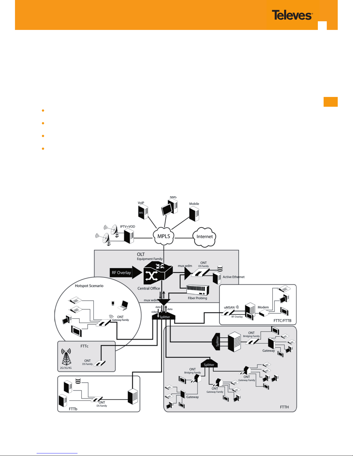
The Figure 2-1 shows possible bridging scenarios for ONT equipment when in an end-to-end PON architecture.
Figure 2-1: ONT applications scenario
Page 8
8
GPON ONT STANDAR
2.1.2 Interoperability
The ONT bridging family equipment complies with ITU-T G.984.x. recommendation as like as G.984.4 (OMCI) ensuring multi-vendor OLT interoperabily with major GPON OLT vendors.
The ONT bridging family equipment is certied by BBF.247 ONU certication program.
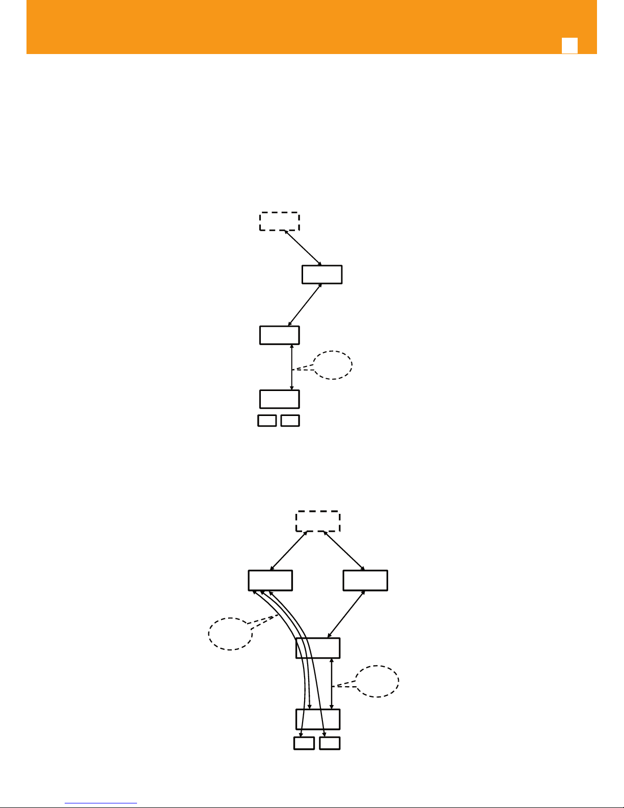
BBF.247 ONU certication program certies ONT link layer conguration and management protocol, OMCI, Figure 2-2, as dened by ITU-T G.984.3,
ITU-T G.984.4 and ITU-T G.988.
OSS
EMS
OLT
ONT
RGW STB
OMCI
Network Topolo gy
OLT/ONT
Management
(TL1, SNMP)
Figure 2-2: Link Layer Conguration and Management
IP-based services conguration and management is achieved by means of the TR-069 protocol as dened by Broadband Forum. This procedure
takes for granted that previously the link layer connectivity has been achieved.TR-069 is then transparent to the OLT, since the TR-069 connections
are established between the ACS and the ONTs,Figure 2-3.
OSS
EMS
OLT
ONT
RGW STB
ACS
TR069
OMCI
Network Topolo gySubscriber Service
OLT/ONT
Management
(TL1, SNMP)
Figure 2-3: IP Based services-TR069 conguration
Page 9
EN
9
2.1.3 Services
The ONT supports the following services:
Voice over IP (VoIP) service;
Broadband Internet Access:
High bit rate data for High Speed Internet service – HSI;
IPTV service;
Analog video service (RF Overlay);
Mobile Backhaul service.
2.1.3.1 Internet over GPON
GPON is a point-to-multipoint passive optical network, in which unpowered optical splitters are used to enable a single optical ber to serve
multiple premises, typically 1-64.
A PON consists of an optical line terminal (OLT) at the central oce and a number of optical network terminals (ONT) at the customer premises.
Downstream signals are broadcasted to all premises sharing multiple bers. Encryption can prevent eavesdropping. Upstream signals are combined using a multiple access protocol (Time Division Multiple Access - TDMA). The OLT queues data to the various ONT terminas in order to provide time slot assignments for upstream communication.
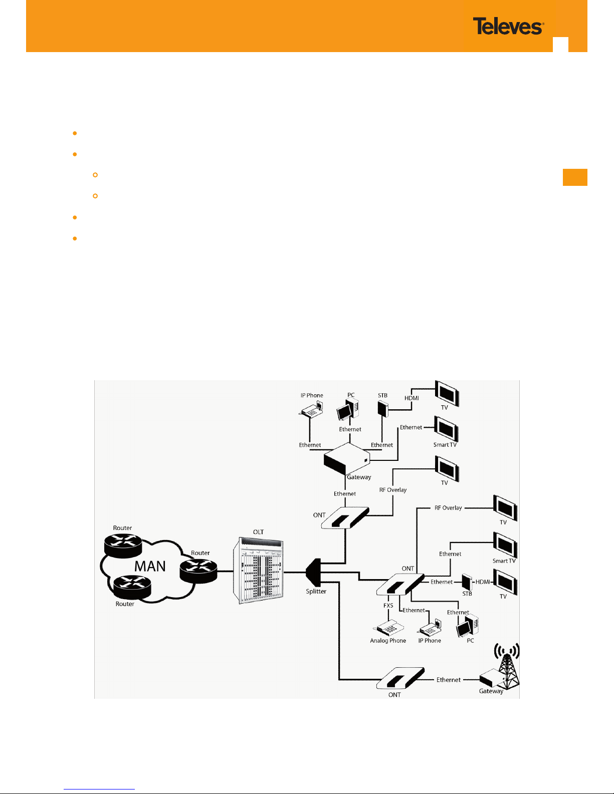
In Figure 2-4 it is shown a scenario for Internet service user access through an ISP network.
Figure 2-4: Optical ber Internet service user access
Page 10
10
GPON ONT STANDAR
The communication between client equipment (ONT) and the ISP access routers (MAN edge) is made by an optical ber-based passive architecture (ITU-T G.984 Recommendation). The GPON network acts as a Layer 2 Ethernet metropolitan network. Access network assures and controls
the media (MAC) communication through a TDMA scheme, introducing GEM (GPON Encapsulation Method) in between to adapt TDM layer to
Ethernet.
The used protocol stack is shown in Figure 2-5.
IP
ETHERNET
GEM
TDM/TDMA
Figure 2-5: Stack of protocols for GPON architecture
Several transmission containers (T-CONT) are assigned to each user. Each T-CONT has an associated GEM port and each GEM port has a VLAN
identier and an 802.1p priority level.
The ONT classies the trac depending on the VLAN and the marked priority, and routes it over the corresponding T-CONT/GEM port. Thus for
frame multiplexing, GEM and T-CONT ports are used for uplink while the downlink only use the GEM ports feature.
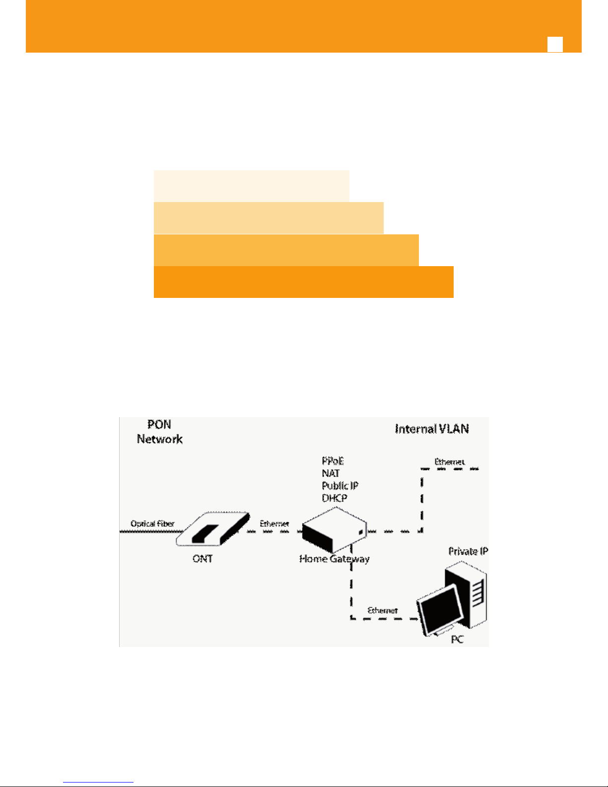
The CPE architecture is shown in Figure 2-6.
Figure 2-6: CPE architecture
Internet access is provided through the Home Gateway (HG) to obtain a public Internet IP.
The home gateway allocates a private IP address to each client through DHCP, making the addresses conversion through NAT for Internet output.
The home gateway establishes PPPoE session with the ISP network, which authenticates the user for Internet access. The user must be a service
subscriber and the service must be provisioned at the OLT where the ONT is connected to.
Page 11

EN
11
2.1.3.2 IPTV service
For the IPTV service the ONT also behaves like a Layer 2 bridging device. For this service, the ONT has a specic GEM PORT for Multicast. This same
GEM PORT is requested by the user in order have access to the various IPTV channels. Every time a user request a new channel, the ONT will send
to OLT a IGMP packet requesting that Channel. The ONT is also responsible for implementing the snooping for the channels that the user requests.
2.1.3.3 RF Video Overlay
PON RF video overlay service is the way to deliver a broadcast TV service over a PON ber network. This video overlay service is foreseen to provide
mainly broadcast video transmission in contrast to unicast and/or multicast IP video transmission which is used for IPTV and/or Video-On-Demand
having the need for a Set-Top-Box or a Smart TV at the customer premises.
Standardization bodies (ITU for GPON and IEEE for GEPON) have excluded the use of the 1550 -1560nm wavelength window for IP transmission on
PONs and have even continued with this approach for the upcoming 10GPON and 10GEPON standards. The 1550-1560nm wavelength window is
thus exclusively reserved for the video overlay transmission and by that mean an option to of¬foad unicast and/or multicast video transmission
from the IP PON transmission link.
Within the ONT RF Video Overlay feature implementation is also an option to deliver a avoured TV channel pack service by the use of a group of
embeeded RF analog lters that can be remotely managed (NMS) in order to enable each individual commercial TV Channel pack, Figure 2-7.
Band pass lters for premium channel service
Remote conguration of the lters from the management system
RF Overlay Signal Spectrum
Base TV Channel Service Pack
Premium TV Channel Service Pack
PW
Hz
Figure 2-7: RF Overlay analog lter feature
Tipically an extra ber testing signal (1650nm) for optical network probing is also added to the PON optical communication link.
2.1.3.4 Voice
ONT voice service provisioning could be made through OLT congurations over OMCI messages or could be downloaded (FTP) from the OLT up
to the ONT after the ONT registration on the PON network.The ONT bridging family equipments have the ability to deliver the Voice service over
two types of interface:
Logical interface (VLAN encapsulation)
If the ONT has no FXS ports and the VoIP service is transparently forwarded from the OLT up to the Home Gateway (and vice versa) within a previously dened voice VLAN. ONT respects the dened priority and implements the trac encapsulation from its own Ethernet interface into a
specic T-CONT/GEM-Port over the PON interface and up to the OLT equipment.
Page 12
12
GPON ONT STANDAR
Physical interface (FXS ports)
The ONT has physical RJ11 FXS interfaces. In this version of the ONT equipment, voice interfaces are terminated in the equipment by means of FXS
(RJ11) connections.The RJ11 analog terminals adapter function is auto/self-congured, integrated (analog/VoIP) and associated with a dened
SIP or Megaco (H.248) user.
The ONT will allow VoIP or NGN (Next Generation Network) trac from devices connected to the RJ11 or RJ45 interfaces, towards the same internal
VLAN.
Appart of the SIP and Megaco (H.248) self-conguration, it is also possible to make modications in the voice service congurations by updating
the ONT SW through download from the OLT via OMCI.
The ONT equipment has a DHCP client (ONT 769503-4GE-2FXS) to get an IP address, alternatively the ONT could be congured with a static IP (ONT
769503-4GE-2FXS). The conguration of the static IP or DHCP client is related to the WAN side and is enabled by the OLT.
2.1.3.5 Multiple QoS per VLAN
The ONT supports 802.1p QoS per VLAN services in which several ows (one per allowed pbit) are embedded in the same VLAN. According to the
applied conguration, the ONT performs a per-ow QoS policy: dropping trac marked with not allowed pbits and limiting to the congured
value the data rate of the allowed ows.
The ONT performs transparent VLAN translation. It is transparent to upper layer protocols, such as ARP, RIP, DHCP, IGMP, PPP, etc.
2.1.3.6 Mobile Backhaul
Due to the large increase on the bandwidth demand of the mobile backhaul networks to support 3G/4G services, PON networks are a natural option for its access component. ONT also supports this mobile backhaul service by mean of a Layer 2 bridging communication channel. Depending
on the interconnection of the mobile backhaul network architecture, ONT transports mobile data trac over a dened combination of VLAN/GEM
PORT/T-CONT. This same conguration should be known and provisioned at the OLT and upper layer network architecture.
2.1.4 Policing / Rate Limiting.
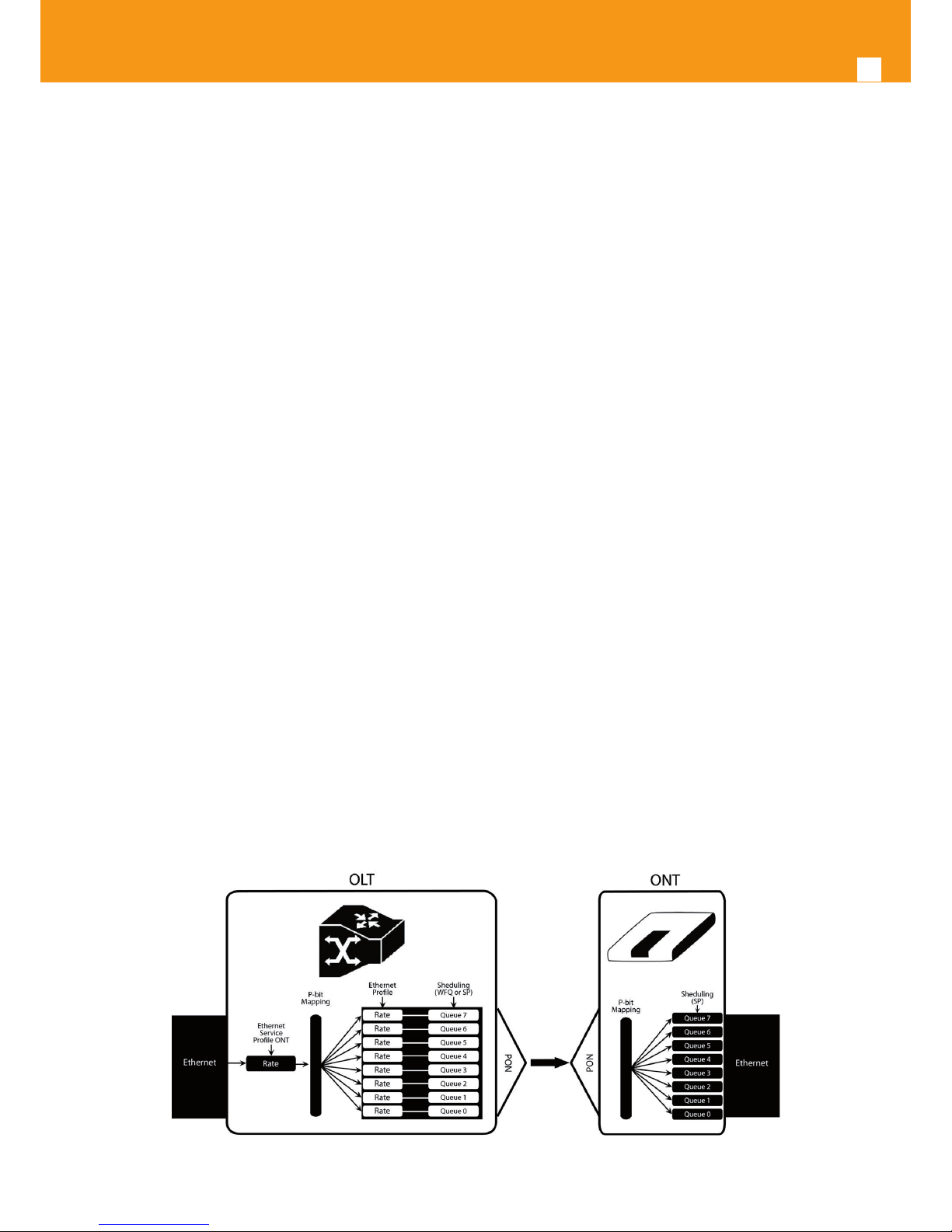
2.1.4.1 Downstream QoS
The OLT system provides several QoS mechanisms, that can be targeted to the ow characterized by one or two VLAN according with the type of
service, or can be targeted to the packets priority, where each p-bit is mapped in one of eight queues of each port.
For each of OLT ports are associated eight queues, for each of these queues is possible to congure the p-bit mapping in one of the queues, the
scheduler type (Strict Priority or Weighted Fair Queuing) and the minimum and maximum bandwidth of each queue.
In the downstream direction the ingress trac rst passes by a policer congured to each ONT service, which is dened by one or two tags. After
this the trac is put in a queue according with the p-bit/queue mapping. Each of these queues is associated with a scheduler and a policer. Then
the trac ows to the GPON interface and when it arrives to the ONT it will pass by a mapping block which will map the trac in one of the
eight queues according with the p-bits, these queues have a Strict Priority scheduler in order to guarantee that the most prioritized trac passes
rst.
Figure 2-8: Downstream QoS Diagram
Page 13
EN
13
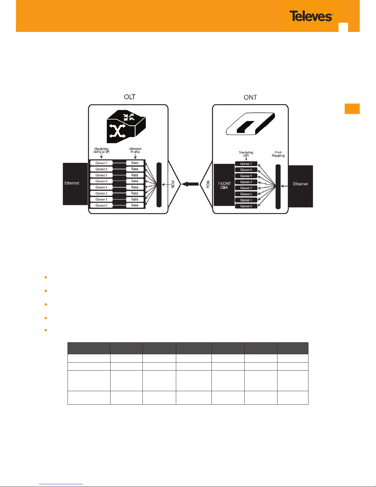
2.1.4.2 Upstream QoS
In the upstream direction, for each T-CONT the ingress trac in the ONT passes by a mapping block that maps the trac in one of the eight queues
according with the p-bit, these queues have a Strict Priority Scheduler. The ONT “waits” until the OLT assigns a transmission timeslot for that TCONT, so that the most prioritized queues are the ones that transmit rst. In the OLT ingress, the trac is put into a queue according with what
is dened in the queue/p-bit mapping. Each of these queues has an associated scheduler and policer that control the trac sent to the uplink.
Figure 2-9: Upstream QoS Diagram
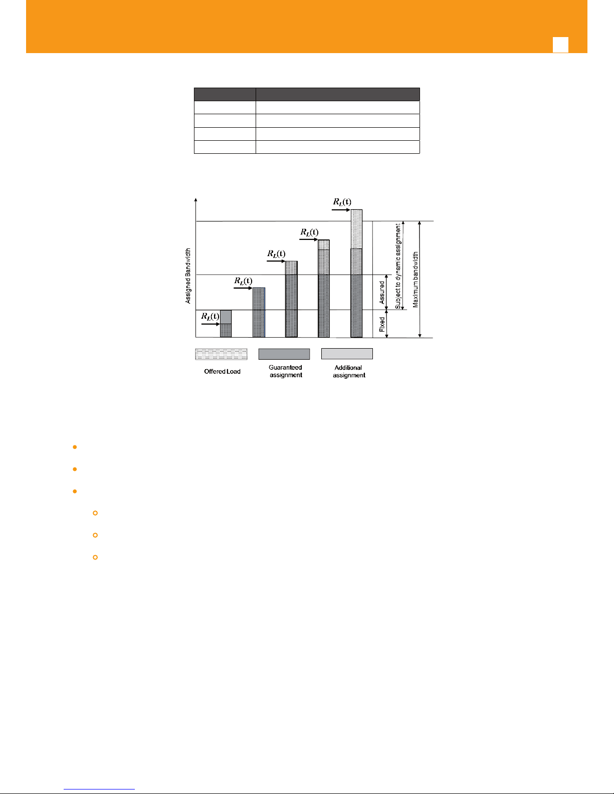
2.1.4.3 Dynamic Bandwidth Allocation (DBA)
The DBA (Dynamic Bandwidth Allocation) is available in order to optimize the upstream bandwidth. This mechanism consists in dening an adequate T-CONT to the service trac in question. There are ve types of T-CONT, dened by the Fixed, Assured and Maximum Parameters:
Type 1: Only xed Bandwidth;
Type 2: Only Assured Bandwidth;
Type 3: Assured+Maximum Bandwidth;
Type 4: Only Maximum Bandwidth (Best Eort);
Type 5: Fixed+Assured+Maximum Bandw
T-CONT Type 1 Type 2 Type 3 Type 4 Type 5 Units
Fixed BW- R
F
R
F1
0 0 0 R
F5
[b/s]
Assured BW- R
A
0 R
A2
R
A3
0 R
A5
[b/s]
Max Bw - R
M
RM1 = R
F1
RM2 = R
A2
R
M3
> R
A3
R
M4
RM5 >
RF5 + R
A5
[b/s]
Bandwidth Eligibility
0 0 Non-Assured
BW - R
NA
Best-Eort
- R
BE
RNA / R
BE
Table 2-1: T-CONT types denition
In each GPON interface there is 1024 Alloc-ID (T-CONT identiers) available, provided to manage ONT services. They are distributed in the following way:
Page 14
14
GPON ONT STANDAR
Alloc-ID Allocation Type
0-127 Default Alloc-ID (Dynamic or Static)
128-255 Reserved
256-639 Dynamic or Static
640-1023 Static
Table 2-2: Alloc-ID’s distribution by T-CONT type
Figure 2-10: Trac distribution by service/client
2.1.4.4 Upstream QoS scenarios Upstream QoS scenarios
8 priority queues
Strict-priority
Upstream Scheduling
Strict Priority (currently supported)
Strict Priority + rate controller (currently supported)
Strict Priority + WFQ (can be SW supported)
2.1.5 Interfaces
2.1.5.1 GPON
The ONT GPON layer as G.984.x uses 1490nm downstream and 1310nm upstream of the optical wavelengh, with 2,488Gbps downstream and
1,244Gbps upstream by using an SC/APC protected optical connector.
2.1.5.2 Ethernet
Ethernet is the wired LAN technology and is revised in the IEEE 802.3 standard. At the OSI reference system, Ethernet is at the Data Link layer. In the
ONT equipment the LAN type of physical interface is 10/100/1000BASE-T AUTO-MIX Ethernet type over RJ45 conectors.
2.1.5.3 RF Overlay
Broadcast video signal travels over ber from the CO in the 1550nm wavelength and is demuxed and converted in the ONT to a F conector (75
Ohm) RF Overlay interface to deliver a RF TV signal going from 47MHz up to 862MHz of bandwidth. As it was already referred in one of the previous
sub-chapters, ONT may also implement multiple analog ltering of the RF Interface in order to turn the open RF Spectrum in a group of sliced TV
channels packs that are remotely enabled from the NMS.
Page 15

EN
15
3. General Specications
3.1 PON Optical Interfaces
Items Unit
B+ C+
ONT Tx ONT Tx
Nominal bit rate
Mbps
1244.16 1244.16
Operating wavelength
nm
1260-1360 1260-1360
Line code
--
Scrambled NRZ Scrambled NRZ
Minimum ORL of ODN
dB
>32 >32
Mean launched power MIN
dBm
+0.5 +0.5
Mean launched power MAX
dBm
+5 +5
Launched optical power without input to the Tx
dBm
Less than Min
sensitivity -10
Less than Min
sensitivity -10
Maximum Tx Enable 16 16
Maximum Tx Disable 16 16
Extinction ratio
dB
>8.2 >8.2
Tolerance to the Tx incident light power
dB
>-15 >-15
SLM Laser – MAX −20 dB width
nm
1 1
SLM Laser – MIN SMSR
dB
30 30
ONT Rx ONT Rx
Receiving bit rate
Mbps
2488.32 2488.32
Receiving wavelength
nm
1480-1500 1480-1500
Max reectance of equipment, measured at Rx wavelength
dB
<-20 <-20
Bit error ratio
--
<-10
-10
<-10
-10
Minimum sensitivity
dBm
-27 -30*
Minimum overload
dBm
-8 -8*
Upstream optical penalty
dB
0.5 0.5
Consecutive identical digit immunity
bit
>72 >72
Tolerance to reected optical power
dB
<10 <10
ONT Rx Video
Receiving wavelength
nm
1550-1560
Table 3-1: Optical interfaces
* ONT RX= -8~-30 dBm (The ONT sensitivity assumes the use of the optional RS (255,239) FEC capability of the G-PON TC layer with the current
class B+ ONU detector technology; The ONU overload is set at –8 dBm to be common with the class B+ value, even though in this application –10
dBm is sucient).
Optical solution: B+ and C+.
Connector type: SC/APC.
IEC 60825-1: “Class 1 Laser Product’’.
The B+ and C+ triplexer is embedded on the ONT equipment version.
Page 16
16
GPON ONT STANDAR
ONU Single Fiber - G.984.2 (03/2003) + G.984.2 Amd 1 (02/2006) and 2 (03/2008), G.983.3 (03/2001).
3.2 Optical Metering
The equipment measures the downstream received power from the OLT in 1490nm and reports this value through OMCI. The accuracy of the
measurement is +/- 3dBm, maximum. Optionally, ONT has also the chance to have an embeded optical reective component in order to increase
the FTTH probing capabilities in a 50 centimeters resolution factor, which turns to have a single probing system to probe all GPON network ONTs
even when its number increases over Million customers.
3.3 Wavelenght Filtering
The optical interface has WDM lters that allow GPON coexistence with RF video services (1550-1560nm) and the new generation of NGPON1
technology, according to G.984.5 Recommendation.
ITU-T Rec. G987.1 is also granted for XGPON, (following FSAN NG-PON2).
In order to face the nal user´s demands, current GPON networks have to confront the rst evolution in terms of terminals equipments and actual
infrastructure. Migration will be available through a new wavelength planning, by allowing the co-existence of two dierent technologies over
the same ber. The ITU-T Rec. G987.1 provides a mechanism for GPON to XGPON migration with the possibility to achieve 2.5Gbps upstream path.
Nominally downstream will be 10 Gbps.
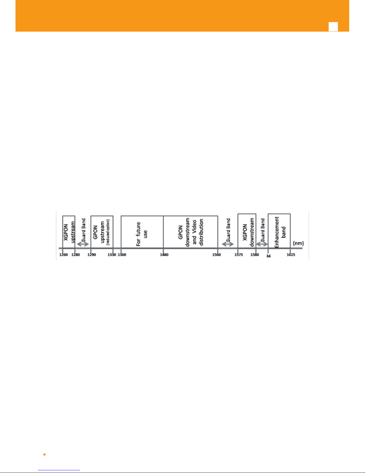
The next gure depicts the wavelength planning of ITU-T Rec. G987.1
Figure 3-11: Wavelength planning
In order to accomplish to that plan, the upstream wavelength for GPON must be restricted to ONU (ONT) equipment based on the ordinary DFB
lasers, while the XGPON downstream signal range is dened from 1575 nm to 1580 nm and the XGPON upstream signal from 1260 nm to 1280
nm. For the coexistence of XGPON and GPON over the same ber, the CO requires a WDM lter that combines the downstream signal (1490 nm,
1555 nm and 1577 nm), isolating the 1310 nm and 1270 nm upstream signal, with the video signal. Also the wavelength of 1650 nm, used for ber
monitoring, has to be handled.
In addition, ONT devices require the use of a triplexer type transceiver that include an integrated lter or a discrete WDM lter to distinguish the
dierent signals that may be present on the ber. The current networks, equipped with ONT in accordance with the current ITU-T Rec. G984.5, will
be easily updated to XGPON.
Class B+ optical budget are the nominal requirement for coexistence of GPON and XGPON over the same optical ber. Taking in account this requirement, the ber network architecture will not limit the future of the service provider business since GPON architectures, respecting B+ class
of the GPON, are easily updated by placing newest terminal equipments, namely XOLT and XONT, and by replacing the current WDM lter by the
new one in order to handle the new XGPON signals.
XGPON must support/emulate all GPON legacy services in case of total migration.
Like GPON, XGPON is required to support triple play services (data, voice and video), as well as mobile backhauling (accurate frequency/phase/
time synchronization) application through its high quality of service and high bit rate feature capabilities. Access to Ethernet services such as
point-to-point, multipoint-to-multipoint and rooted-multipoint Ethernet Virtual Connection services should be provided. Finally, as a global requirement, XG-PON needs to support IPv6.
3.4 GPON/Ethernet characteristics
GPON/Ethernet characteristics supported, both functional level and GTC-OMCI conguration, corresponds with the general mandatory characteristics dened in ITU-T G.984.3, G.984.4 and G.988 Recommendation:
PON interface: downstream operating rate 2.488 Gbits/s, upstream operating rate 1.244 Gbits/s;
Page 17

EN
17
32 T-CONT and 256 simultaneous GEM ports;
1:64 SR is granted once optical power transmission from the OLT side is up from -27/30dBm;Unmarked or marked bandwidth management;
Upstream and downstream FEC;
Downstream AES encryption;
Ethernet ow control in client´s port: 802.3x and 802.3ab;
Ability to classify and modify VLAN labels (single or double labeling);
Ability to support multiple VLAN tags per service (Internet, IPTV, VoIP, ACS, etc) from Residencial Gateway. And ability to translate those
VLAN to one specic service VLAN on OLT side, like, IPTV service VLAN, Internet Service VLAN (SVLAN and CVLAN), and VoIP Service VLAN;
802.1 DSCP for CoS support;
IEEE 802.1Q and 802.1p support;
Multicast snooping support IGMPv2 and IGMPv3;
Firmware upgrade through the PON interface following the mechanisms specied in the ITU-T G.984.4 and G.988, including a safe dual
rmware updates image system and the ability of back-up, allowing the SINGLE PORT ONT start in case the software download fails, to
enable a new software update.
3.5 GPON management
The system supports the conguration according to the recommendations described in ITU-T, G.984, G.988 and BBF TR-156.
Specically the next functionalities are obtained via OMCI for diagnostic (counters and alarms):
ONT conguration checking of the services provisioned;
Acquisition of the physical parameters of the SINGLE PORT GPON ONT interface;
Trac counters, statistics, errors, GPON interface status: by VLAN, by trac type, by priority;
Trac counters, statistics, errors, GbE interface status are only available by port;
Conguration parameters of services provisioned in the ONT: T-CONT, GEMPORT, VLAN and GPON MAC tables;
Alarms/events included in the standards mentioned above.
3.6 RF TV Channel slicing characteristics
ONT Model
ONT 769503-
SFU B
ONT 769503-
SFU C
ONT 769503-
SFU D
ONT 769503-
SFU E
ONT 769503-
SFU F
Number of
channels
- 15 15 15 15
- - - - 25
- - - - 35
Table 3-2: Overlay characteristics
Up to 3 TV channel packs may be implemented with 15, 25 and 35 channels each in a total bandwidth of 47MHz-862MHz.
Page 18

18
GPON ONT STANDAR
3.7 General Features
Features ONT 769503-SFU ONT 769503-4GE-
2FXS
ONT 769503-MBH
GPON
Singlemode Optical Fiber Cable (SC/APC
Connector)
1x 1x 1x
Ethernet
10/100/1000Base-T
Direct or crossover AUTO-MDIX UTP CAT5E
cable (RJ45)
1x 4x 1x
FXS Ports
Voice / Fax RJ11 connector
N.A. 2x N.A.
Video RF connector
F Type
1x 1x N.A.
Primary Power Connection (VDC)
(1)
12 (± 15%) 12 (± 15%) -48 (± 20%)
Primary Power Connection (VAC)
(1)
230 (50Hz ±2Hz) 230 (50Hz ±2Hz) 230 (50Hz ±2Hz)
Power Supply (W) 8.4 (model B)
7 (model D/E)
15 8
MTBF (h) 200000 190000 250000
Size (mm) 210x210x40 210x210x40 240x420x136
Temperature (⁰C) -5 to +70 -5 to +70 -5 to +70
Humidity (%) 0 to 95 0 to 95 0 to 95
NOTES:
(1) An LPS power source is used to power the ONT equipment:
US/Canada:
The ONT must be powered by an external Listed Limited Power Source (LPS) or Class 2 Power source. The external
power adapter must be LPS certied.
Rest of the World:
The ONT must be powered by an External CB approved Limited Power Source (LPS).
Table 3-3: General Features
Page 19

EN
19
EMC
Standards
EMC Directive 89/336/EEC, EMC Addendum Directive
92/31/EEC, EMC Addemdum Directive 91/263/EEC
(Telecommunications Terminal Equipment Directive)
Emissions EN50081-1, EN55022
Immunity EN50082-1, EN61000-4-2, EN61000-4-3, EN61000-4-4
Operating Limits
Temperature EN300019
Relative humidity, maximum EN300019
Environmental Standards Acoustic noise ISO 3743 (<45dBa)
Power and Grounding
ETSI ETS 300 253: January 1995
ETSI EN 300 132-2 V2.1.1 (2003-01)
Optical Safety ALS - Automatic Laser Shutdown
Safety and Protection EN/IEC 60950-1
Mechanical Resistance EN300019
Quality CE - Conformité Européenne
Certication BBF.247 G-PON
Table 3-4: Standards
Page 20

20
GPON ONT STANDAR
4. Setup
4.1 Before installing your ONT device
Check for site’s environmental conditions and look for power and optical access points nearby.
Do not install the device in environments where the temperature or humidity exceeds the standard limits.
This device is a passive cooling device. There are thermal holes in the surface of the box. To prevent the overheating do not obstruct
these thermal holes.
The ONT device is not designed for outdoor setup. Pleae place it in a convenient indoor/cabinet environment.
Use only the provided power kit. The use of a 3rd party power adapter may not guarantee its proper operation.
To avoid any hazard or damage in your eyes, please never look directly into a bre optic connector.
Never assume that the laser beam is inactive or that the optical bre is switched o.
4.2 How to Setup your ONT
The ONT may be installed horizontally on a at surface, wall mounted and ETSI rack (ONT 769503-MBH), quick steps for both of these setups are
described below.
Wall-mount
Remove the ONT lower cover;
Mount the cover on the wall using two screws inserted into the mountings shown in Figure 41(c). The lower mounting is used to regulate
the spatial orientation of the box. The space between the two screws should be about 4.8 cm;
Place the optical cable in one of the openings, (a) or (b) shown in Figure 4-12;
Pass the optical cable, in a clockwise direction, round the circular guide inside the ONT, wrapping it round as many times as necessary;
Fit the ONT into the cover as shown in Figure 4-12;
Attach the ber to the optical connector inside the ONT;
Place a 3 mm plastic clip round the support and the optical cable before the point at which the cable exits the box Figure 4-12(d). Tighten
this just enough to ensure the optical ber will not move;
Close the ONT
Figure 4-12: Optical cable installation –wall mount
Page 21

EN
21
Horizontal position
Open the ONT lower cover;
Place the optical cable in one of the openings, (a) or (b) shown in Figure 4-13;
Pass the optical cable, in a clockwise direction, round the circular guide inside the ONT, wrapping it round as many times as necessary;
Attach the bre to the optical connector inside the ONT;
Place a 3 mm plastic clip round the support and the optical cable before the point at which the cable exits the box Figure 4-13(c). Tighten
this just enough to ensure the optical bre will not move;
Close the ON
Figure 4-13: Optical cable installation – Horizontal mount
ETSI rack
Remove the ONT cover;
Mount the equipment on a ETSI 19’’ rack using the 4 supplied screws.
Place the optical patchcord (SC/PC termination) in the rack ber accomodation structure in order to promote a correct cabling manage-
ment up to the equipment optical interface connector.
Place the electrical CAT5E ethernet cable in the rack electrical cabling accomodation structure in order to promote a correct cabling
management up to the equipment ethernet interface connector.
Place the power cabling (reduntant paths) from the power box up to the TRIDENT power cord connectors.
Figure 4-14: ONT Rack Mount (ONT 769503-MBH)
Page 22
22
GPON ONT STANDAR
4.3 Interface connection
4.3.1 ONT 769503-SFU
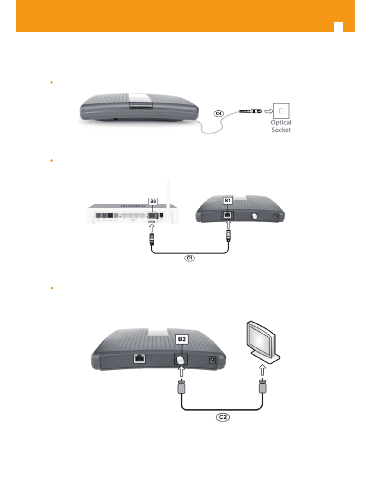
Connect the optical cable (C4) from the ONT 769503-SFU to the optical socket;
Figure 4-15: ONT 769503-SFU interfaces connection 1 (PON Interface)
Connect the Ethernet UTP CAT5E (C1) cable (direct or crossover) from the ONT 769503-SFU Ethernet port (B1) to the Home Gateway’s
WAN port (B6);
Figure 4-16: ONT 769503-SFU interfaces connection 2 (WAN interface)
Connect the coaxial RF cable (C2) from the F-type connector (B2) on the ONT 769503-SFU to the RF input of a TV or the RF input of
the local CATV network;
Figure 4-17: ONT 769503-SFU interfaces connection 3 (RF Overlay Interface)
Page 23
EN
23
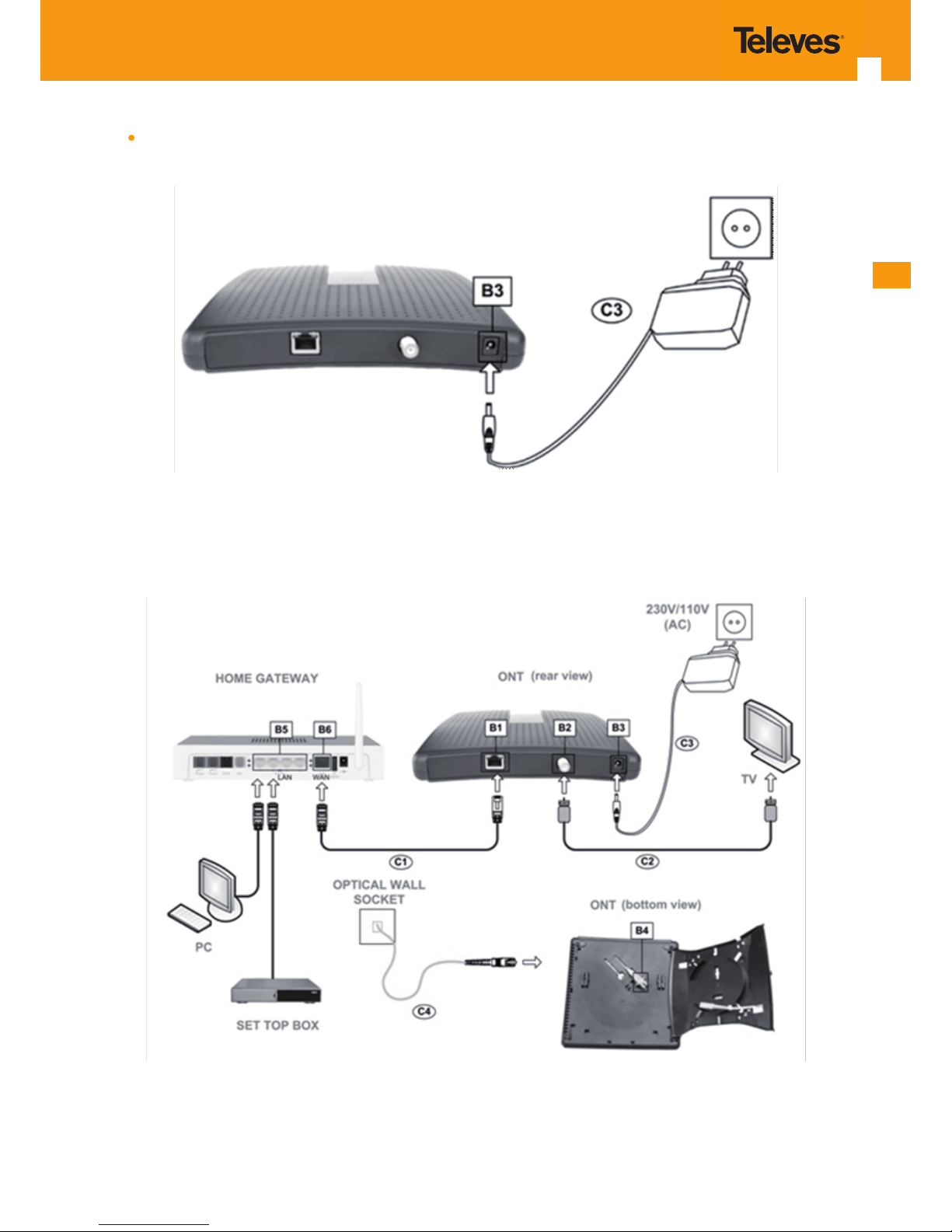
Connect the DC connector from the supplied (C3) converter (230V AC/12V DC) to the DC input on the ONT 769503-SFU (B3) and con-
nect the adapter to a 230V AC electrical socket.
Figure 4-18: ONT 769503-SFU interfaces connection 5 (Power Interface)
4.3.1.1 General Overview of ONT 769503-SFU Connections
The following gure shows the connections to be made between the ONT 769503-SFU and the Home Gateway.
Figure 4-19: ONT 769503-SFU connections
Page 24

24
GPON ONT STANDAR
Nº Description
B1
RJ45 Port - 10/100/1000Base-T
Ethernet with AUTO-MDIX
B2
(1)
Video RF Connector, F type
B3 12VDC Power Connector
B4 SC/APC ONT’s Internal Connector
B5 RJ45 LAN Ports (Home Gateway)
B6 RJ45 WAN Port (Home Gateway)
C1 Ethernet UTP CAT5E Cable (straight or crossover)
C2 Cable with F-type connectors, Coaxial 75 Ohm
C3 12VDC / 1A Power Adapter
C4 Single-mode Optical Cable with SC/APC Connector (GPON)
Notes:
(1) –Optional. Depends on the ONT 769503 SFU model
Table 4-1: ONT 769503-SFU connectors and cables
4.3.2 ONT 769503-4GE-2FXS
Connect the optical cable (C4) from the ONT 769503-4GE-2FXS to the optical socket;
Figure 4-20: ONT 769503-4GE-2FXS interfaces connection 1 (PON Interface)
Connect the Ethernet UTP CAT5E (C1) cable (direct or crossover) from the ONT 769503-4GE-2FXS’s Ethernet port (B2) to the Home
Gateway’s WAN port (B7) and/or an Ethernet port from the PC/Set Top Box;
Figure 4-21: ONT 769503-4GE-2FXS interfaces connection 2 (WAN + LAN interfaces)
Page 25
EN
25
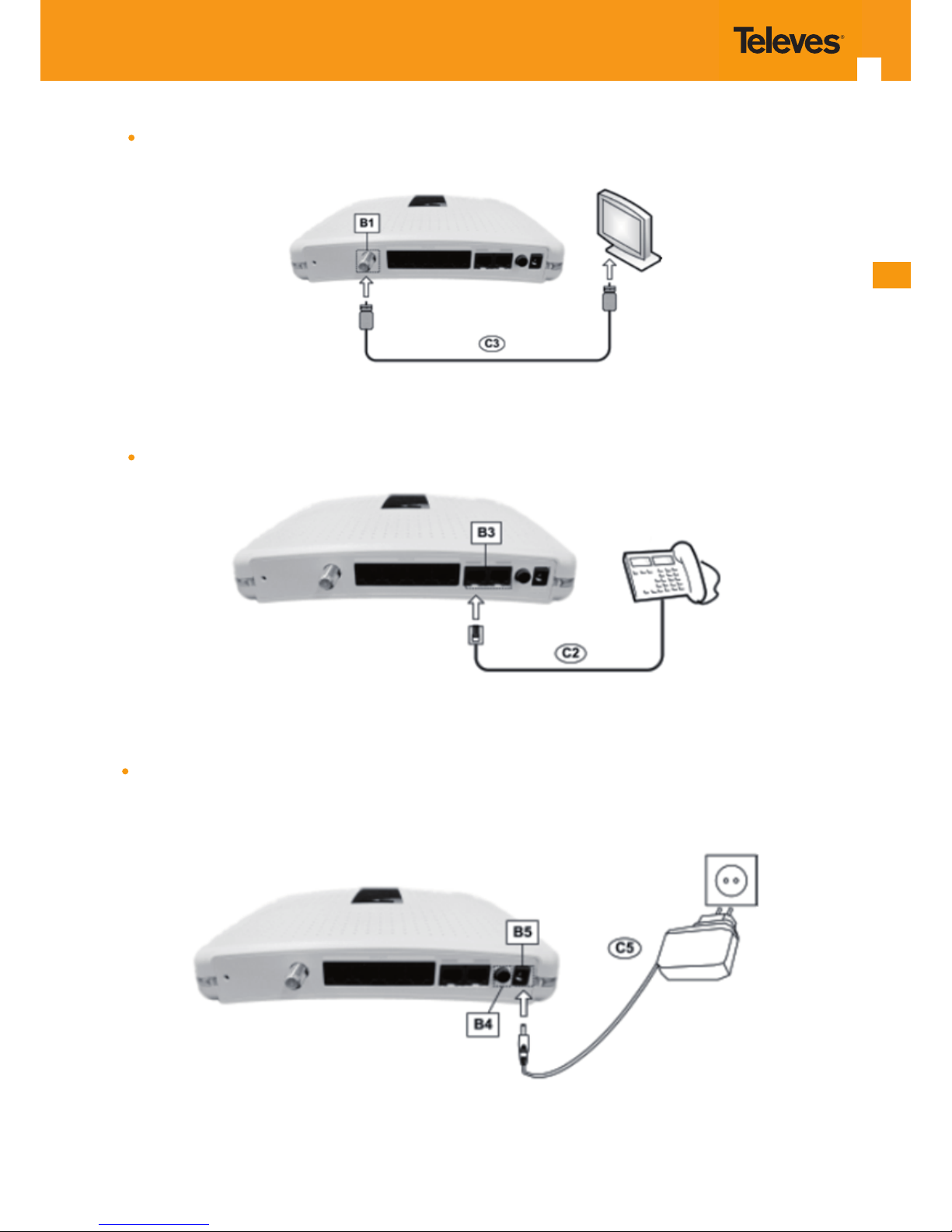
Connect the coaxial RF cable (C3) from the F-type connector (B1) on the ONT 769503-4GE-2FXS to the RF input of a TV or the RF input
of the local CATV network;
Figure 4-22: ONT 769503-4GE-2FXS interfaces connection 3 (RF Overlay Interface)
Connect the telephone cable (C2) to one of the RJ11 FXS ports on the ONT 769503-4GE-2FXS (B3) to a telephone/fax;
Figure 4-23: ONT 769503-4GE-2FXS interfaces connection 5 (FXS Interface)
Connect the DC connector from the supplied (C5) converter (230V AC/12V DC) to the DC input on the ONT 769503-4GE-2FXS (B5) and
connect the adapter to a 230V AC electrical socket. Press the ON/OFF button (B4) to power on the device;
Figure 4-24: ONT 769503-4GE-2FXS interfaces connection 6 (Power Interface)
Page 26
26
GPON ONT STANDAR
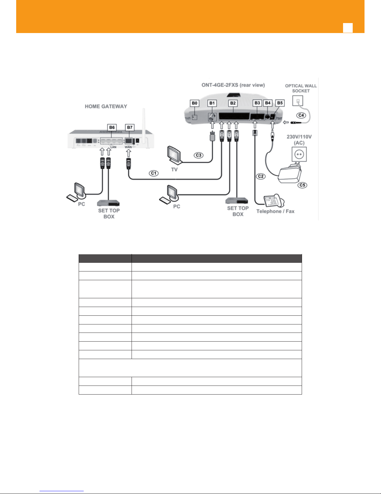
4.3.2.1 General Overview of ONT 769503-4GE-2FXS Connections
The following gure shows the connections to be made between the ONT 769503-4GE-2FXS and the home gateway.
Figure 4-25: ONT 769503-4GE-2FXS Connections
Nº Description
B0 RESET button
B1
(1)
Video RF Connector, F type
B2
4x RJ45 Ports - 10/100/1000Base-T
Ethernet with AUTO-MDIX
B3 2x RJ11 – FXS Ports
B4 ON/OFF button
B5 12V DC Power Supply Connector
B6 LAN RJ45 Ports (Home Gateway)
B7 WAN RJ45 Port (Home Gateway)
C1 Ethernet Cable UTP CAT5E cable (direct or crossover)
C2 RJ11 Telephone cable
C3
Cable with F-type Connectors, Coaxial 75 Ohm
C4 Single-mode Optical Cable with SC/APC Connector (GPON)
C5 12V DC Adapter
Notes:
(1) –Optional. Depends on the ONT 769503 SFU model
Figure 4-26: ONT 769503-4GE-2FXS setup notes
Page 27

EN
27
4.3.3 ONT 769503-MBH ONT 769503-MBH
4.3.3.1 General Overview of ONT 769503-MBH Connections
Figure 4-27: ONT 769503-MBH front pannel
Nº Description
B1
RJ45 Port - 10/100/1000Base-T
Ethernet with AUTO-MDIX
B2 SC/APC ONT’s Internal Connector
B3 -48VDC TRIDENT Power Connector (a)
B4 -48VDC TRIDENT Power Connector (b)
C1 Ethernet UTP CAT5E Cable (straight or crossover)
C2 Single-mode Optical Cable with SC/APC Connector (GPON)
C3 Trilar power cord
C4 Trilar power cord
Figure 4-28: ONT 769503-MBH connectors and cables
Page 28

28
GPON ONT STANDAR
5. Conguration
5.1 ONT activation
The ONT activation process has a distributed set of procedures that allow the connection of a inactive equipment to a PON network. This conguration is done following the procedure described in the OMCI protocol.
5.2 Customization
For customization process, the requirements specied in the G.984.4, G.984.5 and ‘Implementer’s Guide’ in the G.984.4 v1 are taken into account.
5.2.1Software download from the OLT
The software download is made following the OMCI-based procedure included in the ‘Implementer’s Guide’ of the G.984.4 Recommendation.
The Managed Entity (ME) in charge of managing the software download is named Software Image. Per each ME containing independently-manageable software, the ONT creates two software images. Each image will have three attributes:
Valid - if it has been veried that it’s content is an image with executable code;
Committed - if once the ONT is rebooted, it is loaded and executed;
Active - if it is loaded and it is being executed in the ONT.
There can be only one active image and only one commited image at a given moment. The ONT goes through a series of states in order to download and activate a software image. Each state is dened according to the states of the variables of both images. The OLT controls the ONT state
through a series of commands:
Start download
It starts the software download sequence. This action is only valid for inactive and non-commited software images;
Download section
It downloads a section of a software image. This action is only valid for an image that is being downloaded;
End download
It indicates the end of a download sequence, providing the CRC and information about version for the nal verication of the down-
loaded software image. This action is only valid for a software image that is being downloaded;
Activate image
It loads/executes a valid software image. When this action is applied to an inactive software image, the execution of the current code
image is suspended, the associated software image is loaded from the non-volatile memory and the execution of the new code
image is started. When this action is applied over a software image that is active, a reboot is executed;
Commit image
It selects a valid SW image to be loaded and executed by default when the ONT is restarted;
Composition of the Software Image
A software image is divided into sections of 31 bytes, with one section per OMCC message and each section protected by the CRC
of the OMCC. A group of sections makes up a window, and a group of windows constituting the image..
Page 29

EN
29
6. Operation indicators
6.1 ONT 769503-SFU
6.1.1 Status
The ONT 769503-SFU has seven LEDs to indicate its operational status.Example Heading 3
Figure 6-29: ONT 769503-SFU status LEDs
Figure 6-30: ONT 769503-SFU Ethernet port LEDs
Page 30

30
GPON ONT STANDAR
LED Identication LED Status Description
A1 READY
ON Registration in progress
OFF Successfully registered by the OLT
A2 POWER/PROC
ON Power supply ON
OFF Power supply OFF
A3 GPON LINK
Refer to the next table
A4 AUTH (I)
A5 CATV (II)
ON Port administratively connected
Flashing
Port administratively connected with
CAT V
OFF Port administratively disconnected
A6 ETHERNET (Left)
ON With Ethernet connection
OFF No Ethernet connection
A7 ETHERNET (Right) Flashing Ethernet IN/OUT activity
Table 6-1: ONT 769503-SFU LED status
The following combination of GPON LINK (A3) and AUTH (A4) LEDS reects the various states that the ONT is in during the process of conguration
and communication with the OLT (Optical Line Terminal).
ONT Status
LED Status
Description
A3 GPON Link A4 Auth
1 - Initial OFF OFF Initial State
2 - Standby Flashing OFF
ONT 769503-SFU is waiting for initial congu-
ration by the OLT
3 - Serial-Number Flashing Flashing The OLT is conguring the ONT 769503-SFU
4 - Ranging Flashing ON ONT 769503-SFU and OLT synchronisation
5 - Operation ON ON ONT 769503-SFU’s normal operational status
6 - POPUP Flashing OFF Loss of optical signal detected
7 - Emergency-Stop ON OFF Anomalous event
Table 6-2: ONT 769503-SFU states
6.1.2 Final checks
Check, using the following table, if the ONT 769503-SFU has been successfully registered on the network
LED LED Status Device
A1 ON > OFF
ONT 769503-SFUA2, A3, A4 and A6 ON
A5 Flashing*
‘Power’,
‘Broadband’
and ‘Internet’
ON Home-Gateway
Note: * When the RF video server is active.
Table 6-3: ONT 769503-SFU LED nal checks
Page 31

EN
31
6.1.3 Troubleshooting
The table below, according to the LEDs status, identies a possible cause and describes the procedure to x the problem.
LED State Probable Cause Solution
POWER (A2) OFF
ONT 769503-SFU not
powered
Verify that the DC power jack is correctly connected to the ONT 769503-SFU and the power
adapter at the wall power socket.
ETHERNET (Left) (A6)
OFF
ETHERNET cable not
connected correctly
Verify that the ETHERNET cable is correctly connected to the ONT 769503-SFU’s ETHERNET Port
and to the WAN Port at the Home Gateway (and
not to a LAN Port for e.g.). Use another Ethernet
cable
GPON LINK (A3) OFF
Anomaly in the optical
ber signal
Verify that the optical cable is correctly connected
to the ONT 769503-SFU’s internal optical port and
to the optical wall socket. Verify that the ber is
intact, it is clean, without cuts, scratches or bends.
AUTH (A4) OFF
GPON LINK (A3) ON ONT 769503-SFU deac-
tivated by the network
administrator
Contact the technical support.
AUTH (A4) OFF
CATV (A5) OFF
CATV deactive at the
ONT 769503-SFU
Contact the technical support.
GPON LINK (A3) Blinking
Authentication Error at
the ONT 769503-SFU
Contact the technical support.
AUTH (A4)
OFF or
Blinking
Table 6-4: ONT 769503-SFU troubleshooting
Page 32

32
GPON ONT STANDAR
6.2 ONT 769503-4GE-2FXS
The ONT 769503-4GE-2FXS has several LEDs to indicating the equipment operational status.
6.2.1Status
Figure 6-31: ONT 769503-4GE-2FXS LEDs
LED ID LED Status Description
A1 POWER
ON Power supply ON
OFF Power supply OFF
A2 to A5 ETHERNET
ON With Ethernet connection
OFF No Ethernet connection
Flashing Ethernet IN/OUT activity
A6 to A7 VOIP
OFF Service not congured or registration failure
ON Service congured and authenticated
Flashing Telephone o the hook
A10 GPON LINK
See table below
A11 AUTH
A13 CATV
ON Port administratively connected
OFF Port administratively disconnected
Flashing Port administratively connected to CATV
A8, A9, A12,
A14 and A15
Not used
Table 6-5: ONT 769503-4GE-2FXS LED status
Page 33

EN
33
The following combination of GPON LINK (A10) and AUTH (A11) LEDS reects the various states that the ONT 769503-4GE-2FXS is in during the
process of conguration and communication with the OLT (Optical Line Terminal).
ONT 769503-4GE2FXS Status
LED Status
Description
A10 GPON Link A11 Auth
1 - Initial OFF OFF Initial State
2 - Standby Flashing OFF
ONT 769503-4GE-2FXS is waiting for
initial conguration by the OLT
3 - Serial-Number Flashing Flashing
The OLT is conguring the ONT
769503-4GE-2FXS
4 - Ranging Flashing ON
ONT 769503-4GE-2FXS and OLT synchronisation
5 - Operational ON ON
ONT 769503-4GE-2FXS’s normal opera-
tional status
6 - POPUP Flashing OFF Loss of optical signal detected
7 - Emergency-Stop ON OFF Anomalous event
Table 6-6: ONT 769503-4GE-2FXS states
6.2.2 Final checks
Check, using the following table, if the ONT 769503-4GE-2FXS has been successfully registered on the network.
LED LED Status Device
A1, (A2/A3/A4/A5), A10 and A11 ON
ONT 769503-4GE2FXS
A13 Flashing*
A6/A7, ‘Power’, ‘Broadband’ and ‘Internet’
ON**
ON Home-Gateway
Table 6-7: ONT 769503-4GE-2FXS LED nal checks
* When the RF video server is active.
** When the VoIP service is active.
Page 34
34
GPON ONT STANDAR
6.2.3 Troubleshooting
The table below, according to the LEDs status, identies a possible cause and describes the procedure to x the problem.
LED State Possible Cause Solution
POWER (A1) OFF
No power supply to the
ONT 769503-4GE-2FXS
- Check that the power cable is correctly connected to both the ONT 769503-4GE-2FXS
and the adapter at the electrical socket.
ETHERNET (A2 to
A5)
OFF
ETHERNET cable incorrectly
connected
- Check that the ETHERNET cable is properly
connected to the ONT 769503-4GE-2FXS’s
ETHERNET port and the Home Gateway’s
WAN port and not, for example, to a LAN port.
- Change the ETHERNET cable.
GPON LINK (A10) OFF
Anomaly in the optical
bre signal
- Check that the optical cable is correctly
inserted in both the ONT 769503-4GE-2FXS’s
internal optical connector and the optical
socket.
- Check that the bre is intact, is not dirty and
has not been cut or twisted.
AUTH (A11) OFF
GPON LINK (A10) ON ONT 769503-4GE-2FXS
deactivated by the administrator.
Contact the technical support.
AUTH (A11) OFF
CATV (A13) OFF
CATV deactivate in the ONT
769503-4GE-2FXS.
VOIP (A6 to A7) OFF
VoIP deactived in the ONT
769503-4GE-2FXS
GPON LINK (A10) Blinking
Error in ONT 769503- 4GEFXS authentication.
Table 6-8: ONT 769503-4GE-2FXS Troubleshooting
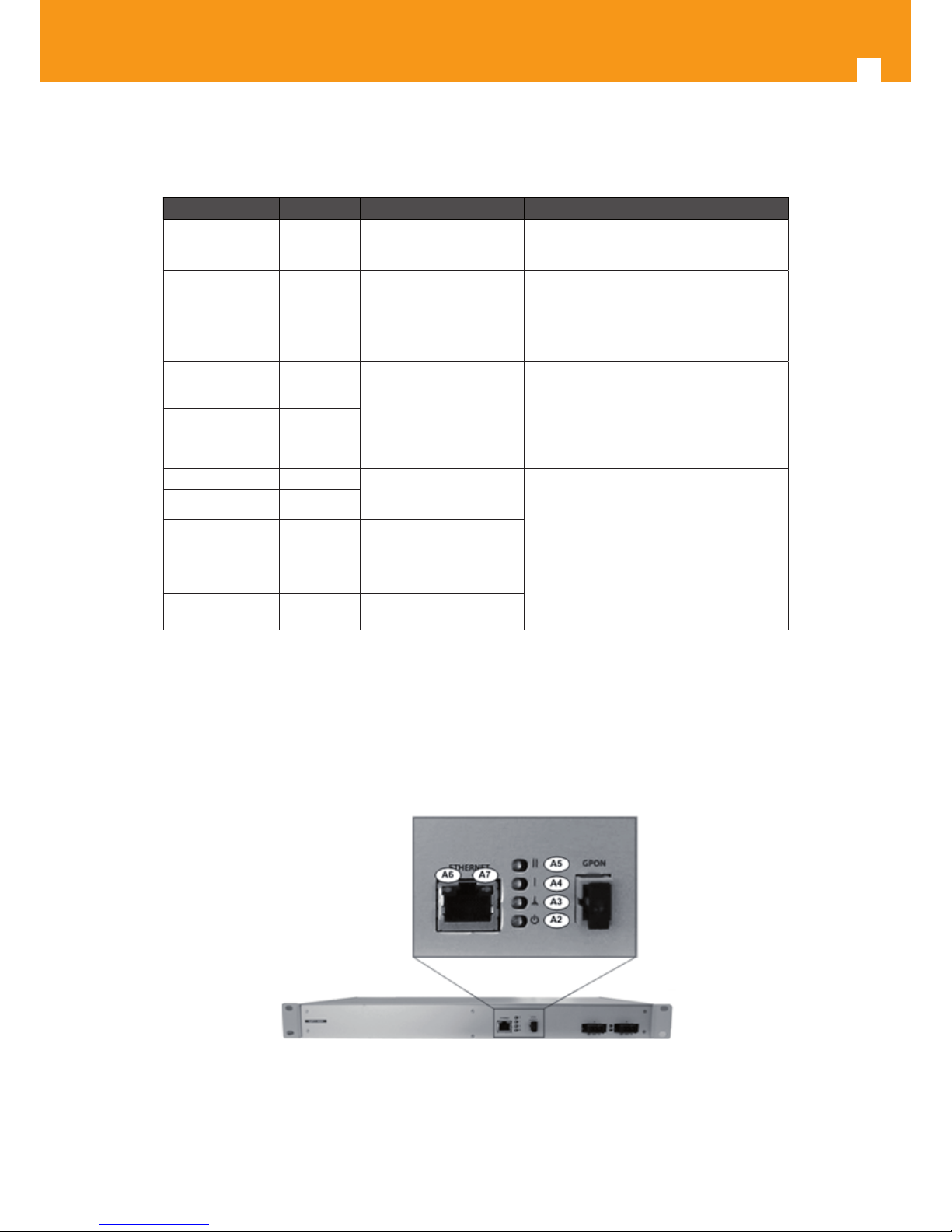
6.3 ONT 769503-MBH
The ONT 769503-MBH has several LEDs to indicate the equipment operational status.
6.3.1 Status
Figure 6-32: ONT 769503-MBH status LEDs
Page 35

EN
35
LED Identication LED Status Description
A2 POWER/PROC
ON Power supply ON
OFF Power supply OFF
A3 GPON LINK
Refer to the next table
A4 AUTH (I)
A5 Not Available
A6 ETHERNET (Left)
ON With Ethernet connection
OFF No Ethernet connection
A7 ETHERNET (Right) Flashing Ethernet IN/OUT activity
Table 6-9: ONT 769503-MBH states
6.3.2 Final Checks
Check, using the following table, if the ONT has been successfully registered on the network.
LED LED Status Device
A2, A3, A4 and A6 ON
ONT 769503-MBH
A5 Flashing
Table 6-10: ONT 769503-MBH LED nal checks
6.3.3 Troubleshooting
The table below, according to the LEDs status, identies a possible cause and describes the procedure to x the problem.
LED State Probable Cause Solution
POWER (A2) OFF ONT not powered
Verify that the DC power TRIDENT connector is correctly connected to the ONT
769503-MBH and the circuit breakers are all
up and running.
ETHERNET (Left)
(A6)
OFF
ETHERNET cable not
connected correctly
Verify that the ETHERNET cable is correctly
connected to the ONT 769503-MBH’s ETHERNET Port and to the WAN Port of the
premises equipment. Use another Ethernet
cable
GPON LINK (A3) OFF
Anomaly in the optical
ber signal
Verify that the optical patchcord is correctly
connected to the ONT 769503-MBH’s internal optical port and to the local ODF. Verify
that the ber is ok, it is clean, without cuts,
scratchings or bendings.
AUTH (A4) OFF
GPON LINK (A3) ON
ONT 769503-MBH deactivated by the network administrator
Contact the technical support.
AUTH (A4) OFF
(A5)
Not Available
Not Available Not Available
GPON LINK (A3) Blinking
Authentication Error at
the ONT 769503-MBH
Contact the technical support.
AUTH (A4)
OFF or
Blinking
Table 6-11: ONT 769503-MBH troubleshooting
Page 36

36
GPON ONT STANDAR
Page 37

EN
37
7. Glossary of Terms and Abbreviations
3G Third generation mobile telecommunications
AAA Authentication, Authorization and Accounting
AC Alternating Current
AC Access Concentrator
ACL Access Control List
ARP Address Resolution Protocol
AS Autonomous System
AUTO-MDIX Medium Dependent Interface Crossover Automatic Choice
BGP Border Gateway Protocol
CAT5E Category 5 Cable
CATV Cable TV
CLI Command-line interface
CO Central Oce
CPE Customer-Premises Equipment
DC Direct Current
DHCP Dynamic Host Conguration Protocol
DNS Domain Name System
EAP-SIM
Extensible Authentication Protocol Method for GSM
Subscriber Identity Module
FTP
FTTH
File Transfer Protocol
Fiber To The Home
FTTC Fiber-To-The-Cell
FXS Foreign eXchange Station
GbE Gigabit Ethernet
GEM GPON Encapsulation Module
GPON Gigabit-capable Passive Optical Network
GSM Global System for Mobile Communications
GW Gateway
HG Home Gateway
HSI High Speed Internet
ID Identication
IEEE Institute of Electrical and Electronics Engineers
IP Internet Protocol
IPTV Internet Protocol Television
ISP Internet Service Provider
ITU-T Telecommunications International Telecommunication Union
L2 OSI Layer 2
L3 OSI Layer 3
LAN Local Area Network
LED Light Emitting Diode
MAC Media Access Control
MAP Mobile Application Part
MBH Mobile Backhaul
ME Managed Entity
Page 38

38
GPON ONT STANDAR
MEGACO Media Gateway Control Protocol
MRU Maximum Receive Unit
MTBF Mean Time Between Failures
NAS Network Access Server
NAT Network Address Translation
NGN
NMS
Next Generation Network
Network Management System
OLT Optical Line Terminal
OMCI ONT Management Control Interface
ONT Optical Network Terminal
OPEX Operational Expenditure
OSI Open Systems Interconnection
PC Personal Computer
PON Passive Optical Network
PPPoE Point-to-Point Protocol over Ethernet
PWLAN Public Wireless LAN
RADIUS Remote Authentication Dial In User Service
RF Radio Frequency
RGW Residential Gateway
RJ11 Registered Jack model 11
RJ45 Registered Jack model 45
SC/APC SC/APC optical connector
SIM Subscriber Identity Module
SIP Session Initiation Protocol
SS7 Signalling System No. 7
SSID Service Set IDentier
STB Set Top Box
TCP Transmission Control Protocol
TDMA Time Division Multiple Access
TR-069 Technical Report 069
TV Television
UDP User Datagram Protocol
URL Uniform Resource Locator
USB Universal Serial Bus
UTP Unshielded Twisted Pair
VAP Virtual Access Point
VID VLAN Identier
VLAN Virtual Local Area Networks
VoIP Voice over Internet Protocol
WAN Wide Area Network
WEP Wired Equivalent Privacy
Wi-Fi Wireless Fidelity
WLAN Wireless Local Area Network
WPA Wi-Fi Protected Access
xBASE-T Ethernet ovr twisted pair technologies
Page 39

Page 40

 Loading...