

Page 1

SPG9000
User Manual
This document supports software version 1.0.
D00013571A April 2023
Page 2

2
Copyrights and Trademark Notices
Copyright © 2023 Telestream, LLC and its Affiliates. All rights reserved. TELESTREAM is a
registered trademark of Telestream, LLC. All other trade names referenced are the
service marks, trademarks, or registered trademarks of their respective companies.
Telestream products are covered by U.S. and foreign patents, issued and pending.
Information in this publication supersedes that in all previously published material.
Specifications and price change privileges reserved.
TELESTREAM is a registered trademark of Telestream, LLC.
Warranty
Telestream on behalf of itself and its Affiliates (“Telestream”) warrants that this product
will be free from defects in materials and workmanship for a period of one (1) year from
the date of shipment. If any such product proves defective during this warranty period,
Telestream, at its option, either will repair the defective product without charge for
parts and labor, or will provide a replacement in exchange for the defective product.
Parts, modules and replacement products used by Telestream for warranty work may
be new or reconditioned to like new performance. All replaced parts, modules and
products become the property of Telestream.
In order to obtain service under this warranty, Customer must notify Telestream of the
defect before the expiration of the warranty period and make suitable arrangements
for the performance of service. Customer shall be responsible for packaging and
shipping the defective product to the service center designated by Telestream, with
shipping charges prepaid. Telestream shall pay for the return of the product to
Customer if the shipment is to a location within the country in which the Telestream
service center is located. Customer shall be responsible for paying all shipping charges,
duties, taxes, and any other charges for products returned to any other locations.
This warranty shall not apply to any defect, failure or damage caused by improper use
or improper or inadequate maintenance and care. Telestream shall not be obligated to
furnish service under this warranty a) to repair damage resulting from attempts by
personnel other than Telestream representatives to install, repair or service the
product; b) to repair damage resulting from improper use or connection to
incompatible equipment; c) to repair any damage or malfunction caused by the use of
non- Telestream supplies; or d) to service a product that has been modified or
integrated with other products when the effect of such modification or integration
increases the time or difficulty of servicing the product.
THIS WARRANTY IS GIVEN BY TELESTREAM WITH RESPECT TO THE PRODUCT IN LIEU OF
ANY OTHER WARRANTIES, EXPRESS OR IMPLIED. TELESTREAM AND ITS VENDORS
DISCLAIM ANY IMPLIED WARRANTIES OF MERCHANTABILITY OR FITNESS FOR A
PARTICULAR PURPOSE. TELESTREAM’S RESPONSIBILITY TO REPAIR OR REPLACE
DEFECTIVE PRODUCTS IS THE SOLE AND EXCLUSIVE REMEDY PROVIDED TO THE
CUSTOMER FOR BREACH OF THIS WARRANTY. TELESTREAM AND ITS VENDORS WILL
NOT BE LIABLE FOR ANY INDIRECT, SPECIAL, INCIDENTAL, OR CONSEQUENTIAL
SPG9000 User Manual
Page 3

DAMAGES IRRESPECTIVE OF WHETHER TELESTREAM OR THE VENDOR HAS ADVANCE
NOTICE OF THE POSSIBILITY OF SUCH DAMAGES.
[W2 – 15AUG04]
TELESTREAM SOFTWARE LICENSE AGREEMENT
THE PROGRAM, OR PROGRAMS, ENCODED OR INCORPORATED WITHIN EQUIPMENT OR
ACCOMPANYING THIS AGREEMENT, IS FURNISHED SUBJECT TO THE TERMS AND
CONDITIONS OF THIS AGREEMENT. RETENTION OF THE PROGRAM FOR MORE THAN
THIRTY DAYS OR USE OF THE PROGRAM IN ANY MANNER WILL BE CONSIDERED
ACCEPTANCE OF THE AGREEMENT TERMS. IF THESE TERMS ARE NOT ACCEPTABLE, THE
UNUSED PROGRAM AND ANY ACCOMPANYING DOCUMENTATION SHOULD BE
RETURNED PROMPTLY TO TELESTREAM FOR A FULL REFUND OF THE LICENSE FEE PAID.
(FOR INFORMATION REGARDING THE RETURN OF PROGRAMS ENCODED OR
INCORPORATED WITHIN EQUIPMENT, CONTACT THE NEAREST TELESTREAM SALES
OFFICE.)
DEFINITIONS
3
"Telestream" means Telestream, LLC, a Delaware limited liability company, and its
Affiliates, or the local Telestream legal entity that is supplying the equipment.
"Program" means the Telestream software product (executable program and/or data)
enclosed with this Agreement or included within the equipment with which this
Agreement is packed. "Customer" means the person or organization in whose name
the Program was ordered.
LICENSE
Customer may:
1. Use the Program on a single machine at any one time; and
2. Copy the Program for archival or backup purposes, provided that no more than
one (1) such copy is permitted to exist at any one time. Each copy of the Program
made by Customer must include a reproduction of any copyright notice or
restrictive rights legend appearing in or on the copy of the Program as received
from Telestream.
Customer may not:
1. Use the Program on more than one machine at any one time;
2. Transfer the Program to any person or organization outside of Customer or the
corporation of which Customer is a part without the prior written consent of
Telestream, except in connection with the transfer of the equipment within which
the programs are encoded or incorporated;
3. Export or re-export, directly or indirectly, the program, any associated
documentation, or the direct product thereof, to any country to which such export
or re-export is restricted by law or regulation of the United States or any foreign
government having jurisdiction without the prior authorization, if required, of the
Office of Export Administration, Department of Commerce, Washington, D.C. and
the corresponding agency of such foreign government;
SPG9000 User Manual
Page 4

4
4. Modify the Program, create derivative works, or merge the Program with another
program;
5. Reverse compile or disassemble the Program for any purpose, beyond the extent
that such activity is expressly permitted by applicable open source licenses or
applicable law notwithstanding this limitation; or
6. Copy the documentation accompanying the Program.
For Programs designed to reside on a single-machine and support one or more
additional machines, either locally or remotely, without permitting the Program to be
transferred to an additional machine for local execution, the additional machines shall
be considered within the definition of "single machine." For programs permitting the
Program to be transferred to an additional machine for local execution, a separate
license shall be required for each such machine with which the Program may be used.
Title to the Program and all copies thereof, but not the media on which the Program or
copies may reside, shall be and remain with Telestream or others for whom Telestream
has obtained a respective licensing right. Customer shall pay when due all property
taxes that may now or hereafter be imposed, levied or assessed with respect to the
possession or use of the Program or this license and shall file all reports required in
connection with such taxes. If the Program or any related documentation is acquired by
or for an agency of the U.S. Government, the Program and documentation shall be
considered “commercial computer software” or “commercial computer software
documentation” respectively, as those terms are used in 48 CFR §12.212, 48 CFR
§227.7202, or 48 CFR §252.227-7014, and are licensed with only those rights as are
granted to all other licensees as set forth in this Agreement.
THE PROGRAM MAY NOT BE USED, COPIED, MODIFIED, MERGED, OR TRANSFERRED TO
ANOTHER EXCEPT AS EXPRESSLY PERMITTED BY THESE TERMS AND CONDITIONS.
UPON TRANSFER OF ANY COPY, MODIFICATION, OR MERGED PORTION OF THE
PROGRAM, THE LICENSE GRANTED HEREIN IS AUTOMATICALLY TERMINATED WITH
RESPECT TO THE PARTY THAT TRANSFERS THE PROGRAM.
TERM
The license granted herein is effective upon acceptance by Customer, and shall remain
in effect until terminated as provided herein. The license may be terminated by
Customer at any time upon written notice to Telestream. The license may be
terminated by Telestream or any third party from whom Telestream may have obtained
a respective licensing right if Customer fails to comply with any term or condition and
such failure is not remedied within thirty (30) days after notice hereof from Telestream
or such third party. Upon termination by either party, Customer shall return to
Telestream or destroy, the Program and all associated documentation, together with all
copies in any form.
LIMITED WARRANTY
The Program is provided "as is" without warranty of any kind, either express or implied.
Telestream does not warrant that the functions contained in the Program will meet
Customer's requirements or that the operation of the Program will be uninterrupted or
error-free.
SPG9000 User Manual
Page 5

TELESTREAM AND ITS VENDORS DISCLAIM ANY IMPLIED WARRANTIES OF
MERCHANTABILITY OR FITNESS FOR A PARTICULAR PURPOSE. LIMITATION OF LIABILITY,
IN NO EVENT SHALL TELESTREAM OR OTHERS FROM WHOM TELESTREAM HAS
OBTAINED A LICENSING RIGHT BE LIABLE FOR ANY INDIRECT, SPECIAL, INCIDENTAL, OR
CONSEQUENTIAL DAMAGES ARISING OUT OF OR CONNECTED WITH CUSTOMER'S
POSSESSION OR USE OF THE PROGRAM, EVEN IF TELESTREAM OR SUCH OTHERS HAS
ADVANCE NOTICE OF THE POSSIBILITY OF SUCH DAMAGES.
THIRD-PARTY DISCLAIMER
Except as expressly agreed otherwise, third parties from whom Telestream may have
obtained a licensing right do not warrant the program, do not assume any liability with
respect to its use, and do not undertake to furnish any support or information relating
thereto.
GENERAL
This Agreement contains the entire agreement between the parties with respect to the
use, reproduction, and transfer of the Program. Neither this Agreement nor the license
granted herein is assignable or transferable by Customer without the prior written
consent of Telestream. This Agreement and the license granted herein shall be
governed by the laws of the state of California. All questions regarding this Agreement
or the license granted herein should be directed to the nearest Telestream Sales Office.
5
THIRD-PARTY SOFTWARE LICENSE
The SPG9000 PTP option uses open source software from the Linux PTP Project (ptp4l),
which is licensed under GPL v2.0. The ptp4l source code has been modified for use on
the SPG9000, so a copy of the modified source code will be made available upon
request in accordance with the GPL v2.0 license. Visit www.telestream.net/telestream-
support/video/support.htm to find contacts in your area.
SPG9000 User Manual
Page 6

6
Contents
Important Compliance and Safety Information 8
Preface 19
Product Description 21
Base Capabilities 22
Optional Capabilities 23
Instrument Installation 25
Rackmount Slides and Rails 26
Power Connection 34
Rear Panel Connectors 36
SFP Module Installation 41
GNSS Antenna Installation 43
System Operation 46
Front Panel Interface 47
Management Network Interface 54
Web User Interface 57
Application Programming Interfaces 63
Presets 69
System Status and Monitoring 72
Indicators 73
Status Information 78
Reference and Time Sources 98
Theory of Operation 99
Reference and Time Sources 104
PRISM MPS and MPD SDI / IP Waveform Monitor User Manual
Page 7

Genlock Reference 111
GNSS Receiver Settings 115
Daily Jam Sync 119
Daylight Saving Time Management 121
Leap Second Management 123
Program Time Counter 125
PTP Operation 127
Theory of Operation 128
PTP Configuration 137
Synchronization Outputs 148
Black Outputs 149
Linear Time Code Input and Outputs 157
Audio Reference Outputs 160
7
System Maintenance 161
Power Supply Monitoring and Replacement 162
Licensed Features 167
Upgrade Instrument Firmware 172
System Oscillator Calibration 175
PRISM MPS and MPD SDI / IP Waveform Monitor User Manual
Page 8

8
Important Compliance and Safety Information
Important Compliance and
Safety Information
United States of America Compliance Notices
Class A Interference Statement
This equipment has been tested and found to comply with the limits for a Class A
digital device, pursuant to Part 15, Subpart B of the FCC Rules. These limits are designed
to provide reasonable protection against harmful interference in a commercial
installation. This equipment generates, uses, and can radiate radio frequency energy
and, if not installed and used in accordance with the instructions, may cause harmful
interference to radio communications. However, there is no guarantee that interference
will not occur in a particular installation. Operation of this equipment in a residential
area is likely to cause harmful interference in which case the user will be required to
correct the interference at his own expense.
FCC Caution
This device complies with Part 15 of the FCC Rules. Operation is subject to the following
two conditions:
1. This device may not cause harmful interference, and
2. This device must accept any interference received, including interference that may
cause unexpected operation.
Safety
UL 61010-1: 2012 R7.19: Safety Requirements for Electrical Equipment for
Measurement, Control, and Laboratory Use - Part 1: General Requirements.
Environmental
Perchlorate Materials: this product contains one or more type CR lithium batteries.
According to the state of California, CR lithium batteries are classified as perchlorate
materials and require special handling.
See www.dtsc.ca.gov/hazardouswaste/perchlorate for additional information.
SPG9000 User Manual
Page 9

Canada Compliance Notices
Department of Communications Radio Interference Regulations
This digital apparatus does not exceed the Class A limits for radio-noise emissions from
a digital apparatus as set out in the Radio Interference Regulations of the Canadian
Department of Communications. This Class A digital apparatus complies with Canadian
ICES-003.
Reglement sur le brouillage radioelectrique du Quadstere des
Communications
Cet appareil numerique respecte les limites de bruits radioelectriques visant les
appareils numeriques de classe A prescrites dans le Reglement sur le brouillage
radioelectrique du Quadstere des Communications du Canada. Cet appareil numerique
de la Classe A est conforme a la norme NMB-003 du Canada.
Safety
CAN/CSA-C22.2 NO. 61010-1-12 + GI1 + GI2 (R2017) + A1: Safety Requirements for
Electrical Equipment for Measurement, Control, and Laboratory Use - Part 1: General
Requirements.
Important Compliance and Safety Information
9
Sécurité
CAN/CSA-C22.2 NO. 61010-1-12 + GI1 + GI2 (R2017) + A1: Exigences de sécurité pour
l'électricité Matériel de mesure, de contrôle et d'utilisation en laboratoire - Partie 1:
Généralités Exigences.
European Union, European Free Trade Association
(EFTA), and United Kingdom Compliance Notices
This equipment may be operated in the countries that comprise the member countries
of the European Union and the European Free Trade Association. These countries, listed
in the following paragraph, are referred to as The European Community throughout
this document:
AUSTRIA, BELGIUM, BULGARIA, CYPRUS, CROATIA, CZECHIA, DENMARK, ESTONIA,
FINLAND, FRANCE, GERMANY, GREECE, HUNGARY, IRELAND, ITALY, LATVIA, LITHUANIA,
LUXEMBOURG, MALTA, NETHERLANDS, POLAND, PORTUGAL, ROMANIA, SLOVAKIA,
SLOVENIA, SPAIN, SWEDEN, UNITED KINGDOM, ICELAND, LIECHTENSTEIN, NORWAY,
SWITZERLAND
Declaration of Conformity
Marking by the “CE” symbol indicates compliance with the Essential Requirements of
the EMC Directive of the European Union 2014/30/EU
This equipment meets the following conformance standards:
SPG9000 User Manual
Page 10

10
Important Compliance and Safety Information
Safety
EN 61010-1: 2010 + A1: Safety Requirements for Electrical Equipment for Measurement,
Control, and Laboratory Use - Part 1: General Requirements Low Voltage Directive
2014/35/EU
Emissions
EN 55032: 2015 + A11: 2020, CISPR 32: 2015, EN 61000-3-2: 2014, EN 61000-3-3: 2013
Immunity
EN 55035: 2017, EN 61000-4-2: 2009,
EN 61000-4-3: 2006 + A1: 2008 + A2: 2010, EN 61000-4-4: 2012,
EN 61000-4-5: 2014 + A1: 2017, EN 61000-4-6: 2014, EN 61000-4-8: 2010,
EN 61000-4-11: 2020
Environments: E2
Warnings
Warning! This is a Class A product. In a domestic environment, this product may cause
radio interference, in which case, the user may be required to take appropriate
measures.
Achtung! Dieses ist ein Gerat der Funkstorgrenzwertklasse A. In Wohnbereichen
konnen bei Betrieb dieses Gerates Rundfunkstorungen auftreten, in welchen Fallen der
Benutzer fur entsprechende Gegenmal nahmen verantwortlich ist.
Attention! Ceci est un produit de Classe A. Dans un environnement domestique, ce
produit risque de creer des interferences radioelectriques, ii appartiendra alors a
l’utilisateur de prendre les mesures specifiques appropriees.
Notes:
1. For Compliance with the EMC standards listed here, high-quality shielded interface
cables should be used.
2. Emissions which exceed the levels required by this standard may occur when this
equipment is connected to a test object.
Environmental Compliance
This section provides information about the environmental impact of the product.
Product end-of-life handling
Observe the following guidelines when recycling an instrument or component:
Equipment recycling
Production of this equipment required the extraction and use of natural resources. The
equipment may contain substances that could be harmful to the environment or
human health if improperly handled at the product's end of life. To avoid release of
such substances into the environment and to reduce the use of natural resources, we
SPG9000 User Manual
Page 11
Important Compliance and Safety Information
encourage you to recycle this product in an appropriate system that will ensure that
most of the materials are reused or recycled appropriately.
This symbol on the product or its packaging indicates that this product complies with
the applicable European Union requirements according to Directives 2012/19/EU and
2006/66/EC on waste electrical and electronic - equipment (WEEE) and batteries.
It also indicates that this product must not be disposed of with your other household
waste. Instead, it is your responsibility to dispose of your waste equipment by handing
it over to a designated collection point for the recycling of waste electrical and
electronic equipment. The separate collection and recycling of your waste equipment
at the time of disposal will help conserve natural resources and ensure that it is recycled
in a manner that protects human health and the environment. For more information
about where you can drop off your waste for recycling, please contact your local
authority, or where you purchased your product.
Battery Recycling
This product may contain a rechargeable battery, which must be recycled or disposed
of properly. Please properly dispose of or recycle the battery according to local
government regulations.
11
Transporting Batteries or products with Batteries in them
The capacity of the lithium-ion secondary battery shipped with this product is under
100 Wh. The lithium content of the installed primary battery is under 1 g. Each battery
meets the applicable requirements of UN Manual of Tests and Criteria Part Ill Section
38.3. Battery quantity is under the limit for shipment according to Section II of the
relevant Packing Instructions from the IATA Dangerous Goods Regulations. Consult
your air carrier for applicability and determination of any special lithium battery
transportation requirements.
Restriction of Hazardous Substances
This product is classified as an industrial monitoring and control instrument, and is
required to comply with the substance restrictions of the RoHS 3 Directives 2011/65/EU
and EU 2015/863.
Korea Compliance Statement
SPG9000 User Manual
Page 12
12
Important Compliance and Safety Information
Taiwan Compliance Statement
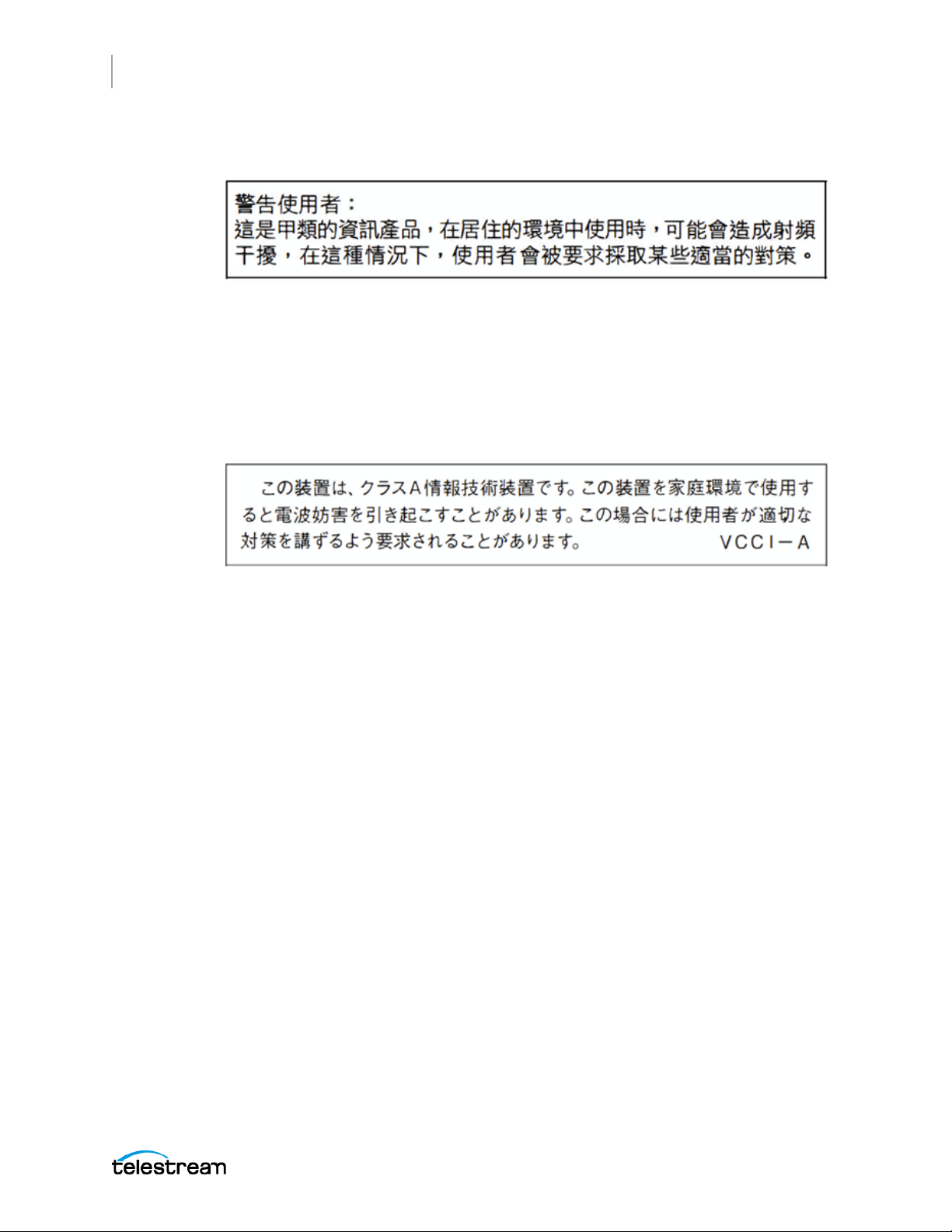
This is a Class A product based on the standard of the Bureau of Standards, Metrology
and Inspection (BSMI) CNS 13438, Class A. In a domestic environment this product may
cause radio interference, in which case the user may be required to take adequate
measures.
Japan Compliance Statement
This is a Class A product based on the standard of the VCCI Council (VCCI 32: 2016). If
this equipment is used in a domestic environment, radio interference may occur, in
which case the user may be required to take corrective actions.
Important Safety Information
This manual contains information and warnings that must be followed by the user for
safe operation and to keep the product in a safe condition. To safely perform service on
this product, see the Service Safety Summary that follows the General Safety Summary.
General Safety Summary
Use the product only as specified. Review the following safety precautions to avoid
injury and prevent damage to this product or any products connected to it. Carefully
read all instructions. Retain these instructions for future reference.
Comply with Local and National Safety Codes
For correct and safe operation of the product, it is essential that you follow generally
accepted safety procedures in addition to the safety precautions specified in this
manual.
SPG9000 User Manual
Page 13

Important Compliance and Safety Information
Product is Designed to be Used by Trained Personnel Only
Only qualified personnel who are aware of the hazards involved should remove the
cover for repair, maintenance, or adjustment. Before use, always check the product with
a known source to be sure it is operating correctly.
While using this product, you may need to access other parts of a larger system. Read
the safety sections of the other component manuals for warnings and cautions related
to operating the system.
When incorporating this equipment into a system, the safety of that system is the
responsibility of the assembler of the system.
To Avoid Fire or Personal Injury
Use proper power cord: Use only the power cord specified for this product and certified
for the country of use. Do not use the provided power cord for other products.
Ground the product: This product is grounded through the grounding conductor of the
power cord. To avoid electric shock, the grounding conductor must be connected to
earth ground. Before making connections to the input or output terminals of the
product, ensure that the product is properly grounded. Do not disable the power cord
grounding connection.
13
Power disconnect: The power cord disconnects the product from the power source. See
instructions for the location. Do not position the equipment so it is difficult to operate
the power cord; it must remain accessible to the user at all times to allow for quick
disconnection if needed.
Observe all terminal ratings: To avoid fire or shock hazard, observe all rating and
markings on the product. Consult the product manual for further ratings information
before making connections to the product. Do not apply a potential to any terminal,
including the common terminal, that exceeds the maximum rating of that terminal.
Do not operate without covers: Do not operate this product with covers or panels
removed, or with the case open. Hazardous voltage exposure is possible.
Avoid exposed circuitry: Do not touch exposed connections and components when
power is present.
Do not operate with suspected failures: If you suspect that there is damage to this
product, have it inspected by qualified service personnel.
Disable the product if it is damaged. Do not use the product if it is damaged or operates
incorrectly. If in doubt about safety of the product, turn it off and disconnect the power
cord. Clearly mark the product to prevent its further operation.
Before use, inspect voltage probes, test leads, and accessories for mechanical damage
and replace when damaged. Do not use probes or test leads if they are damaged, if
there is exposed metal, or if a wear indicator shows.
Examine the exterior of the product before you use it. Look for cracks or missing pieces.
SPG9000 User Manual
Page 14

14
Important Compliance and Safety Information
Use Only Specified Replacement Parts
Do not operate in wet/damp conditions: Be aware that condensation may occur if a
unit is moved from a cold to a warm environment.
Do not operate in an explosive atmosphere.
Keep product surfaces clean and dry: Remove the input signals before you clean the
product.
Provide proper ventilation: Refer to the manual's installation instructions for details on
installing the product so it has proper ventilation.
Slots and openings are provided for ventilation and should never be covered or
otherwise obstructed. Do not push objects into any of the openings.
Provide a safe working environment: Always place the product in a location convenient
for viewing the display and indicators.
Be sure your work area meets applicable ergonomic standards. Consult with an
ergonomics professional to avoid stress injuries.
Use only the Telestream rackmount hardware specified for this product.
Service Safety Summary
The Service Safety Summary section contains additional information required to safely
perform service on the product. Only qualified personnel should perform service
procedures. Read this Service Safety Summary and the General Safety Summary before
performing any service procedures.
To avoid electric shock: Do not touch exposed connections.
Do not service alone: Do not perform internal service or adjustments of this product
unless another person capable of rendering first aid and resuscitation is present.
Disconnect power: To avoid electric shock, switch off the product power and disconnect
the power cord from the mains power before removing any covers or panels, or
opening the case for servicing.
Use care when servicing with power on: Dangerous voltages or currents may exist in this
product. Disconnect power, remove battery (if applicable), and disconnect test leads
before removing protective panels, soldering, or replacing components.
Verify safety after repair: Always recheck ground continuity and mains dielectric
strength after performing a repair.
Terms in the Manual
These terms may appear in this manual:
WARNING: Warning statements identify conditions or practices that could result
in injury or loss of life.
SPG9000 User Manual
Page 15
Important Compliance and Safety Information
CAUTION: Caution statements identify conditions or practices that could result
in damage to this product or other property.
Terms on the Product
These terms may appear on the product:
DANGER indicates an injury hazard immediately accessible as you read the marking.
WARNING indicates an injury hazard not immediately accessible as you read the
marking.
CAUTION indicates a hazard to property including the product.
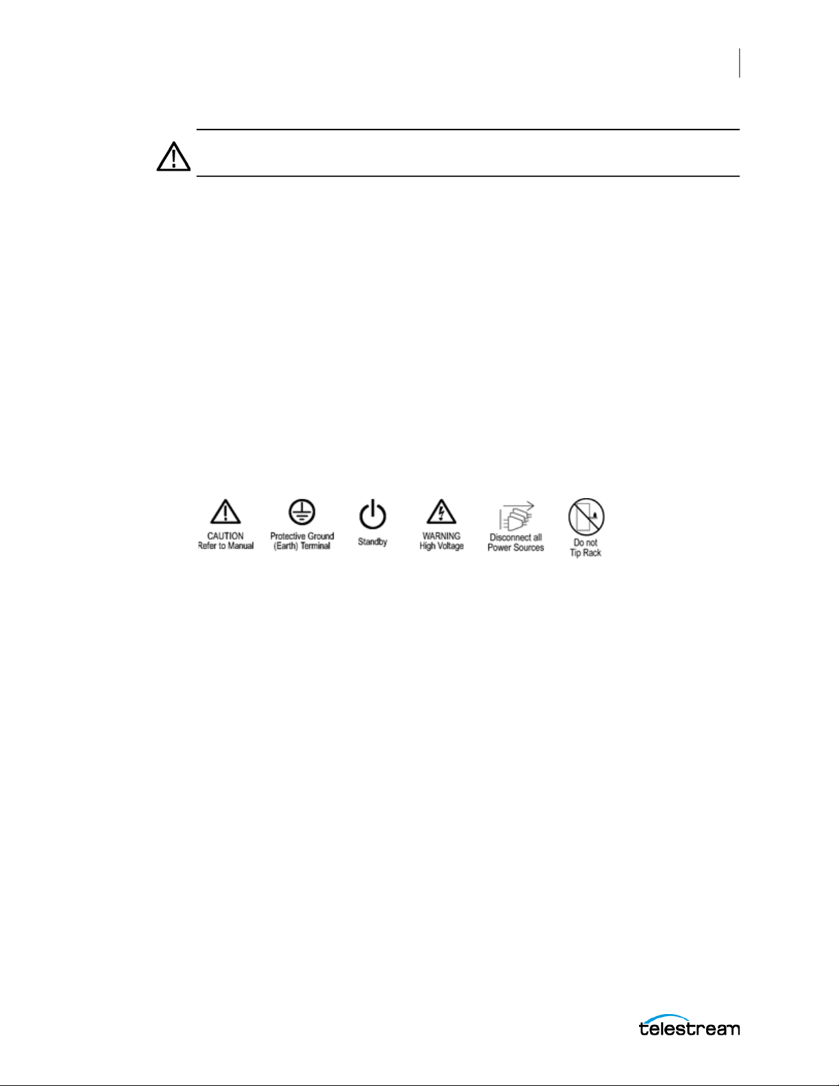
Symbols on the Product
When this symbol is marked on the product, be sure to consult the manual to find out
the nature of the potential hazards and any actions which have to be taken to avoid
them. (This symbol may also be used to refer the user to ratings in the manual.)
15
The following symbol(s) may appear on the product:
General Safety Product Specific Statements
Use the product only as specified. Review the following safety precautions to avoid
injury and prevent damage to this product or any products connected to it.
Carefully read all instructions. Retain these instructions for future reference.
Comply with local and national safety codes.
For correct and safe operation of the product, it is essential that you follow generally
accepted safety procedures in addition to the safety precautions specified in this
manual. The product is designed to be used by trained personnel only.
Only qualified personnel who are aware of the hazards involved should remove the
cover for repair, maintenance, or adjustment.
Before use, always check the product with a known source to be sure it is operating
correctly.
This product is not intended for detection of hazardous voltages.
Use personal protective equipment to prevent shock and arc blast injury where
hazardous live conductors are exposed.
When incorporating this equipment into a system, the safety of that system is the
responsibility of the assembler of the system.
SPG9000 User Manual
Page 16

16
Important Compliance and Safety Information
WARNING: Injury or death can occur as the result of electrical shock. To avoid
electrical shock, do not connect power to the instrument when the top cover is
off. There are dangerous potentials present on the power supply circuit boards
when the power cord is connected.
Disconnect the power cord from a power supply module before you remove the
module from the instrument. Also, do not connect a power cord to a power
supply module while the module is not installed in the instrument. There are
dangerous high voltages on the module when the power cord is connected.
WARNING: Prevent risk of shock or fire by ensuring that the GNSS antenna is
protected from lightning strikes when it is mounted outside a building or facility.
The instrument does not have isolation protection from lightning, so the facility
installation must provide suitable protection for the GNSS antenna external to
the instrument and surge suppression for the cable. Failure to use appropriate
precautions can result in injury or death. It is important the antenna and cable
installation complies with all regulations for the location in which it is installed.
WARNING: To avoid personal injury and instrument damage, do not use slides
provided with other instruments from other kits (for example, General Devices,
Chassis Trak C-300) with the rails from this kit. The locking feature will not
function and will result in an instrument that is not secured properly and could
fall out of the rack, causing personal injury or instrument damage.
WARNING: To prevent the rack-mounted instrument from tipping forward onto
the operator, install the instrument so the operator is able to access all of its rearpanel connectors without pushing down on the instrument. Verify that the rack
does not become unstable with the instrument fully extended. Do not leave the
instrument extended when finished accessing the rear panel.
WARNING: To reduce the risk of injury and equipment damage, make sure that
levers are properly installed. An improperly installed lever can prevent the slide
from locking or prevent the instrument from being removed from the rack. Make
sure that the lever is installed so the long handle is facing forward and the short
hook is facing downward.
WARNING: To prevent injury during product installation, use care not to pinch
hands or fingers in the rails and slides.
SPG9000 User Manual
Page 17

Important Compliance and Safety Information
WARNING: To prevent injury when removing the product from the rack, do not
forcefully and abruptly pull the product from the rack. Pull with the minimum
force required to move the instrument with a consistent, even motion.
CAUTION: The instrument does not have a power switch. When you connect the
power cable to the AC line connector, the instrument powers on.
Do not install or remove a power supply module when a power cord is attached
to that module.
CAUTION: To avoid antenna damage, do not turn on the DC antenna power until
you know that the antenna is designed to handle the selected voltage. Antenna
damage can occur if the antenna is not designed to handle the voltage you
select.
17
CAUTION: Be careful to select the correct screw type for your instrument (metric
or SAE). If the screws do not insert easily (do not use excessive force or you might
damage the threads), it is possible you are using the wrong screw.
CAUTION: To prevent damage to the instrument and rackmount, do not force
the instrument into the rack if it does not slide smoothly. The rails assembly
might need to be adjusted to resolve the problem.
CAUTION: To prevent an unexpected shutdown of the instrument, be sure to
disconnect the correct power cord if you are replacing a faulty power supply
module.
CAUTION: The instrument might automatically reboot at the end of the upgrade
process. Do not perform the upgrade while the instrument is in use as a sync
reference. When the instrument has started to erase the internal flash, do not
remove power from the instrument.
CAUTION: To prevent static damage to the SFP modules, if you remove the SFP
modules from the instrument, always transport the SFP modules in an anti-static
bag or container.
CAUTION: To prevent damage to the SFP modules, remove the SFP modules
before transporting the SPG instrument.
SPG9000 User Manual
Page 18

18
Important Compliance and Safety Information
CAUTION: To prevent dust from contaminating the SFP module, use its cover
when the SFP is not in use. If SPF modules or fiber optic cable have been left
exposed, we recommend it is cleaned before use. This is especially important on
the long-reach, single-mode SFP modules and fiber.
CAUTION: We strongly recommend using the timeout function to keep the
display backlight at a low level when the front panel interface is not actively
being used, to maximize the life of the display backlight.
SPG9000 User Manual
Page 19

Preface
This manual contains information to help you use the SPG9000 timing and reference
system:
● How to operate the instrument using the front panel controls
● How to configure the instrument for network access and operate the instrument
using the web interface
● How to monitor the status of the instrument during normal operation
Where to Find More Information
Preface
19
Other information about your product are available for download at
www.telestream.net/video/resources.htm. The Product Documentation table lists all
the documentation for the SPG9000 timing and reference system.
Product Documentation
Document Manual type Part number Description
SPG9000 User Manual User D00013571x Provides detailed operating information.
Release Notes Release Notes P00010606x Describes the new features,
improvements, and limitations of the
instrument firmware.
Read-this-first User P00010592x Lists all relevant documents.
SPG9000 Installation and
Safety Instructions
SPG9000 Rack Accessory
Installation Manual
Manual, Rackmount
Slides and Rails Kit
User P00010606x Describes how to install and set up a
SPG9000 generator, and provides basic
safety and operating information.
User P0001x Describes how to install an SPG9000
generator in a rack. Provides basic safety
information.
User 071370600x Describes how to connect rack
equipment to an SPG9000 generator.
Provides basic safety information.
SPG9000 User Manual
Page 20

20
Preface
Telestream Contact Information
To obtain product information, technical support, or provide comments on this guide,
contact us using our website, email, or phone number listed.
Resource Contact Information
Telestream Video
Support
Telestream Website: www.telestream.net
International
Distributor Support
Telestream Technical
Writers
Website: www.telestream.net/telestream-support
Email:[email protected]
US and Canada Toll-free: 1-844-219-5329
Outside of US and Canada: 1-503-967-9833
Sales and Marketing Email: [email protected]
Address:
Telestream
848 Gold Flat Road, Suite 1
Nevada City, CA. USA 95959
Website: www.telestream.net
See the Telestream website for your regional authorized
Telestream distributor.
Email: [email protected]
If you have comments or suggestions about improving
this document, or other Telestream documents—or if
you've discovered an error or omission, please email us.
SPG9000 User Manual
Page 21
Product Description
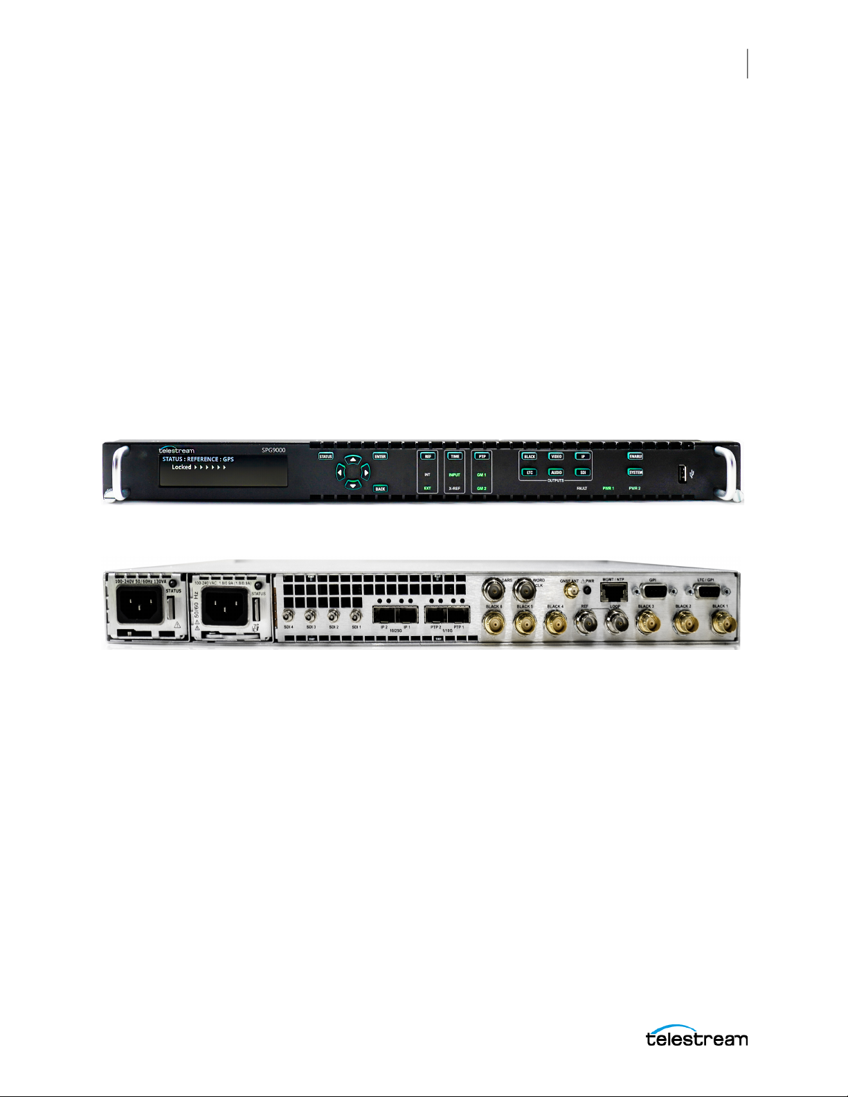
The SPG9000 is a precision multiformat video signal generator and timing system,
suitable for primary synchronization and reference applications. It provides multiple
video, audio, and time reference signals, and it can synchronize to different reference
sources. The instrument uses optional licenses to enable additional functionality, such
as GNSS-based synchronization, PTP (Precision Time Protocol) support, and test signal
generation for SDI and ST 2110 IP interfaces. The sample images show the front and
back of the SPG9000.
Product Description
21
SPG9000 User Manual
Page 22

22
Product Description
Base Capabilities
Base Capabilities
These capabilities and hardware are available on all SGP9000 instruments.
The SPG9000 has six sync outputs that can be configured with independent output
formats (NTSC/PAL black burst and/or HD tri-level sync) and independently adjustable
timing offsets. It includes two dedicated audio reference signal outputs: a 48 kHz word
clock output and an AES DARS (Digital Audio Reference Signal) output.
A high-accuracy, oven-controlled micro-electromechanical system (MEMS) oscillator
provides a stable frequency reference for the system, or the loop-through genlock
input can be used to lock to an external video reference or 10 MHz continuous wave
signal. The Stay GenLock® feature avoids synchronization shock, which can result in
many possible video and audio errors as a result of a sudden change in timing. If the
external reference suffers a temporary disturbance, Stay GenLock® maintains the
frequency and phase of each output signal. When the external reference is restored,
Stay GenLock® ensures that any accumulated clock drift is removed by slowly adjusting
the system clock instead of suddenly forcing the system clock back to the correct
phase.
Time reference outputs are available in multiple formats. Three independent LTC (linear
time code) outputs are available, and a fourth LTC connection can be used as input or
output. Each LTC output has independent frame rate selection, time source (time of day
or program time) and time zone offset. VITC (vertical interval time code) is available on
each NTSC or PAL black output, also with independent time sources and offsets.
For remote access to the instrument, a 10/100/1000BASE-T Ethernet interface is
included. A web-based user interface can be used for all configuration settings and for
monitoring system status. A web-services application programming interface can be
used for all configuration settings and to get status and performance monitoring
information; this enables easy integration with management and dashboard systems.
SPG9000 User Manual
Page 23

Optional Capabilities
These capabilities are available as separately licensed features, and can be added to any
SP9000 at the initial time of purchase or as a later upgrade.
Optional GNSS-based Synchronization
Option SPG9000-GNSS enables an integrated receiver inside the SPG9000 that can
receive GNSS (Global Navigation Satellite System) signals from multiple satellite
constellations (GPS, GLONASS, BeiDou, Galileo, and QZSS) and frequency bands (L1 and
L5). When connected to an external antenna that supplies the standard GNSS RF signal
(for example, SPG9000-ACC-ANT), the SPG9000 can use the GNSS system’s stable
frequency reference.
The GNSS signal also includes a precise time-of-day reference that can be used for all
time code outputs. Similar to the Stay GenLock® feature, the SPG9000 can maintain the
video frequency and phase when the GNSS signal is interrupted, and the Holdover
Recovery mode ensures a shock-free realignment of frequency and phase when the
GNSS signal is restored.
Product Description
Optional Capabilities
23
Optional PTP Support
Option SPG9000-PTP enables two PTP (Precision Time Protocol) engines for IP networkbased synchronization. Two SFP+ ports provide two network interfaces that can
operate at 1 Gbps or 10 Gbps depending on the SFP module type. Each port has an
independent PTP instance that can operate as a primary (grandmaster), follower, or as
an Ordinary Clock that can adaptively change between leader and follower states. With
two instances, the SPG9000 can operate as a dual leader, providing PTP to two separate
networks (such as a primary + backup network pair as used by ST 2022-7); as a dual
follower, synchronized to the GM on either the primary or backup network; or as a
follower on one network and a leader on another, bridging the two separate PTP
domains. A follower instance can be used to monitor PTP operation on the network
without having to function as the reference source of the instrument.
The SPG9000 supports IEEE 1588, ST 2059-2 and AES67 profiles, and each instance can
operate with multicast, unicast, or mixed communication models.
The status of each instance, including performance monitoring measurements such as
offsets, delays and message rates can be viewed on the web interface or retrieved by
the API for integration into management dashboard systems.
The black outputs support a 1 PPS output signal. This is useful for measuring timing
between systems.
Optional Test Signal Outputs
The SPG9000 includes video, audio, and data test signal generation for a variety of
formats on multiple outputs. Option SPG9000-SDI enables four SDI (Serial Digital
Interface) outputs capable of SD, HD, or UHD signals at interface rates up to 12G-SDI.
SPG9000 User Manual
Page 24

24
Product Description
Optional Capabilities
Option SPG9000-IP enables two SFP28 ports for ST 2110 IP stream generation over
25 Gbps or 10 Gbps interfaces depending on the SFP type.
Both the SPG9000-SDI and SPG9000-IP options will be available in a future firmware
update.
Optional Backup Power Supply
For critical applications, the instrument can be configured with a second power supply
module. Under normal operation, the designated backup supply is seldom used,
ensuring that it has maximum remaining life should the primary supply fail. The backup
supply is load-tested each day to verify that it can serve as the primary supply if
necessary. The usage time of each supply is logged as “temperature-weighted hours”, a
metric that best estimates the calculated life of the supply. A front-panel LED indicates
when the supply is nearing its end-of-life. If the primary supply is interrupted for any
reason, the system switches to the backup without any disruption to system operation.
Power supply modules are hot-swappable for easy replacement and feature a locking
mechanism to prevent the power cable from accidental disconnection.
SPG9000 User Manual
Page 25

Instrument Installation
This section describes:
● how to install the SPG9000 into a standard 19-inch equipment rack, it includes a list
of the parts in the mounting kit and the required tools (not included),
● how to connect the SPG9000 to external power,
● the physical connectors on the rear panel of the instrument and which signals are
used with each connector,
● how to install and remove SFP modules, and
● how to connect an external GNSS antenna and its associated cables.
Instrument Installation
25
SPG9000 User Manual
Page 26

26
Instrument Installation
Rackmount Slides and Rails
Rackmount Slides and Rails
The SPG9000 is typically installed in a standard 19-inch equipment rack. The rack
mount kit consists of a pair of slides that are attached to the SPG9000 and a pair of rails
that are attached to the rack. This section describes how to install the slides and rails.
The rack mount kit can be ordered as option SPG9000-RACK at the same time as the
base unit. In this case, the slides are pre-installed onto the SPG9000 before it is shipped.
The kit can also be ordered as SPG9000-ACC-RACK as a standalone kit after the initial
purchase.
Kit Parts List
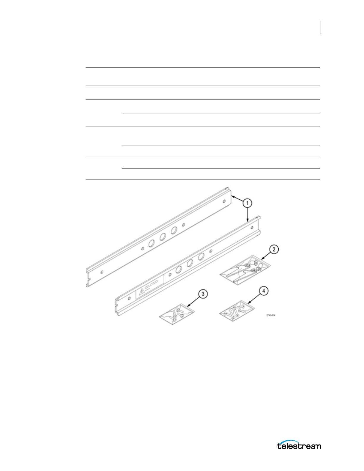
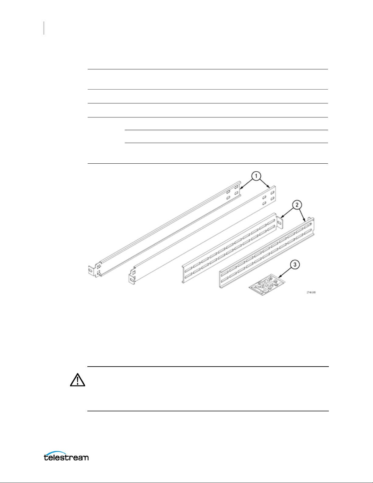
The slides assembly parts list has the parts contained in this kit. The associated figures
show what the parts look like. If your kit was shipped with your instrument, the slides
are already installed.
SPG9000 User Manual
Page 27
Instrument Installation
Rackmount Slides and Rails
Slides assembly parts list
Number in
example Qty Name and description
1 2 BRACKET, RACK, CHASSIS-SIDE
2 2 BRACKET, RACK, LEVER, CHASSIS-SIDE
2 BUSHING, RACK, CHASSIS-SIDE
3 2 SCREW, MACHINE; 8-32 X 0.5, FLH, 100 DEG, STL, ZN PL, PHIL
(SAE)
6 SCREW, MACHINE; 8-32 X 0.375, PNH, STL, ZN PL, PHIL (SAE)
4 2 SCREW, MACHINE; M4X10MM L, FLH, STL, ZN PL, PHIL (metric)
6 SCREW, MACHINE; M4 X 8MM L,PNH, STL, ZN PL, PHIL (metric)
27
SPG9000 User Manual
Page 28
28
Instrument Installation
Rackmount Slides and Rails
Rails assembly parts list
Number in
example Qty Name and description
1 2 BRACKET, RACK, STATIONARY
2 2 BRACKET, RACK, REAR CABINET
3 2 BRACKET, RACK, BAR NUT
8 SCREW, MACHINE; 10-32 X 0.625,TRH, ZINC PLATED STEEL, PHIL
4 NUT ASSY; 10-32 X 0.375 HEX, ZINC PLATED STEEL, LOCK
WASHER
Installation Instructions
This section provides instructions:
● Installing the slides onto the SPG9000 if they are not already installed
● Installing the rails into a standard 19-inch equipment rack
● Installing the instrument into the rails in the rack
WARNING: To avoid personal injury and instrument damage, do not use slides
provided with other instruments from other kits (for example, General Devices,
Chassis Trak C-300) with the rails from this kit. The locking feature will not
function and will result in an instrument that is not secured properly and could
fall out of the rack, causing personal injury or instrument damage.
SPG9000 User Manual
Page 29

Instrument Installation
Rackmount Slides and Rails
Equipment List
These tools are required to install the kit hardware:
● #2 crosshead screwdriver
● 3/8-inch wrench
WARNING: To prevent the rack-mounted instrument from tipping forward onto
the operator, install the instrument so the operator is able to access all of its rearpanel connectors without pushing down on the instrument. Verify that the rack
does not become unstable with the instrument fully extended. Do not leave the
instrument extended when finished accessing the rear panel.
Install Slides
Screw Selection
For the slides installation, this kit provides two sets of screws (metric and SAE), but the
SPG9000 only needs the 3 metric screws.
29
Procedure
Attach the slides to the instrument:
Note: The slides might already be installed on your instrument. If they are, skip this
procedure and go to Installing the Rails.
1. Identify the right rear and left rear of each slide. A warning label is on the outside
side of each slide.
2. Make sure that the rear of the slide is nearest to the rear of the instrument. The front
of each slide has a notch in the center edge.
3. Align the mounting holes on the right slide to the mounting holes on the right side
of the instrument.
4. Use the shorter screws provided (8mm) and a screwdriver with a #2 Phillips tip;
attach the right slide to the right side of the instrument:
CAUTION: Be careful to select the correct screw type for your instrument (metric
or SAE). If the screws do not insert easily (do not use excessive force or you might
damage the threads), it is possible you are using the wrong screw.
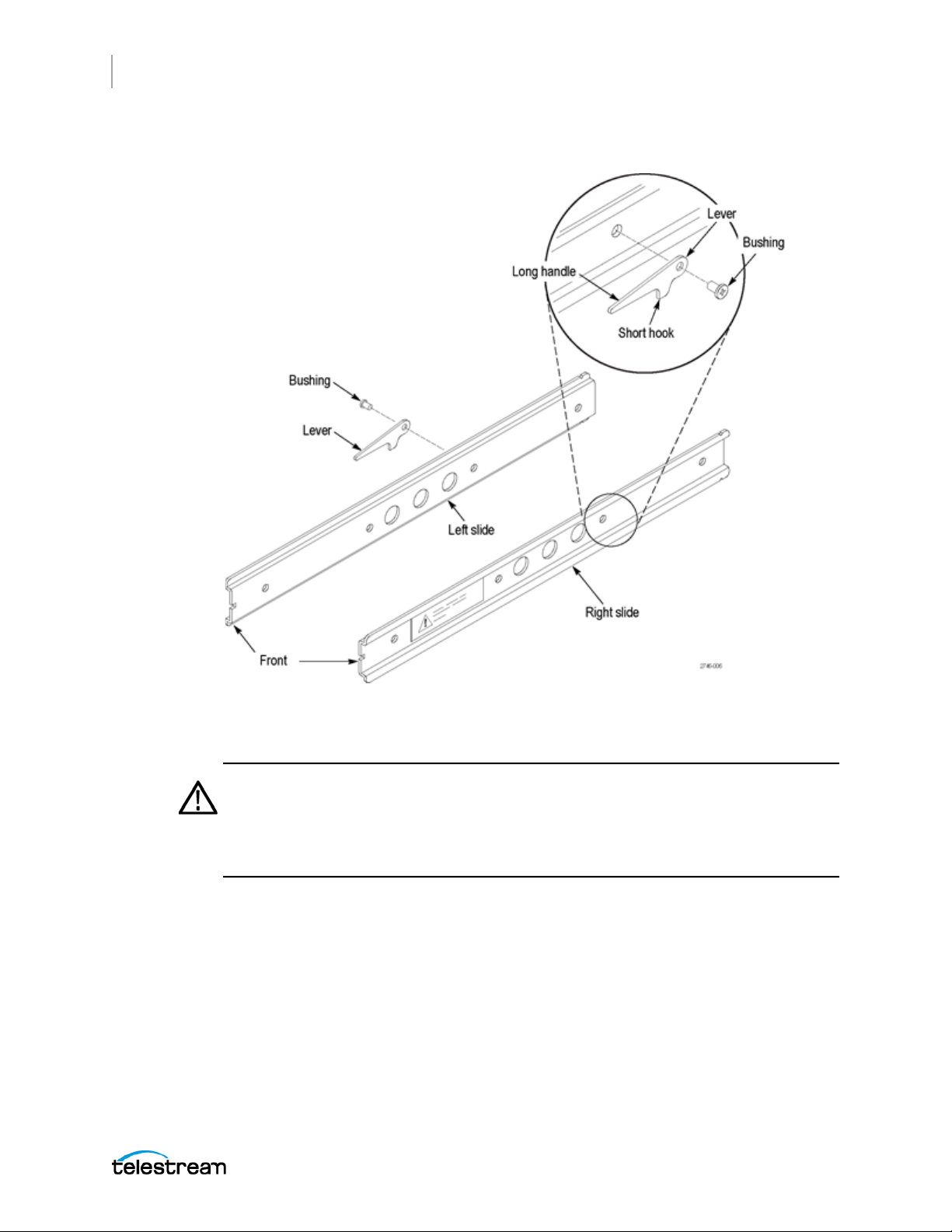
A. Insert the metric screws into the first two mounting holes.
B. Place the lever, with the long handle facing the front of the slide and the short
hook facing downward, over the remaining mounting hole.
C. Insert a metric screw into the bushing for the lever.
D. Insert the bushing and screw into the lever so the lever is attached to the slide
and the slide is secured to the instrument.
SPG9000 User Manual
Page 30
30
Instrument Installation
Rackmount Slides and Rails
The example shows how to attach the slide levers for the SPG9000 instrument.
5. Rotate the instrument to face the left side and repeat this procedure to install the
left slide.
WARNING: To reduce the risk of injury and equipment damage, make sure that
levers are properly installed. An improperly installed lever can prevent the slide
from locking or prevent the instrument from being removed from the rack. Make
sure that the lever is installed so the long handle is facing forward and the short
hook is facing downward.
Install Rails
This two-part procedure describes how to assemble and install the rails in the
equipment rack.
Assemble Rails
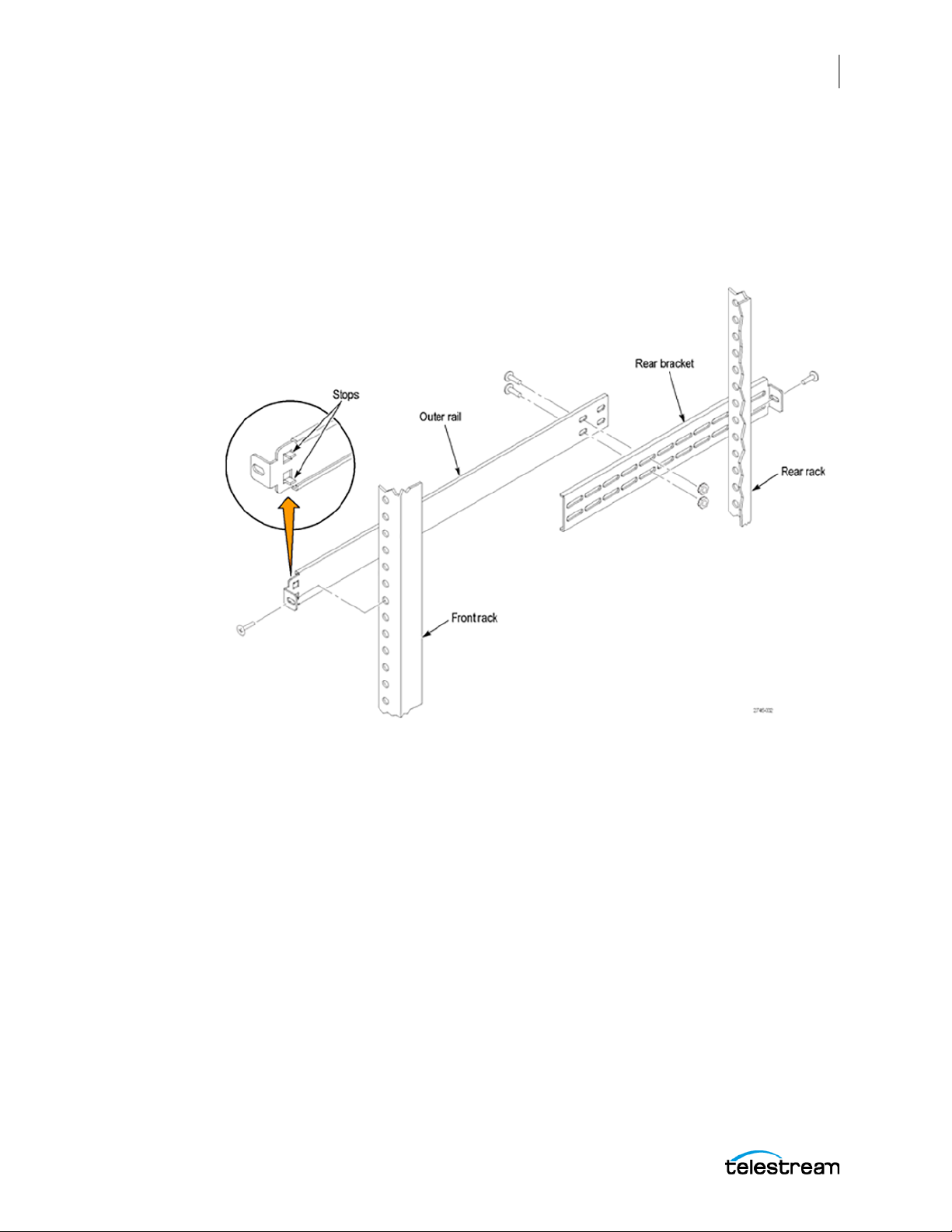
1. Measure the distance between the front and rear rail of the equipment rack.
2. Align the rear bracket to the right rail. Notice that the rear bracket has multiple pairs
of mount-through holes. When aligning the bracket and rail, be sure to select a pair
SPG9000 User Manual
Page 31
Instrument Installation
Rackmount Slides and Rails
of holes that mount the rear bracket so the flange-to-flange distance matches the
front rail to rear rail spacing of the rackmount rack just measured in step 2.
3. Using a screwdriver with a #2 Phillips tip, attach the rear bracket to the right rail
using two 10-32 screws and 10-32 nuts or a bar nut as necessary. Leave the screws
loose so you can adjust the overall length of the rail assembly in the rack.
4. Repeat this procedure to assemble the left rail assembly.
31
Mount Rails
1. Select a ½-inch-spaced hole in the front rack.
2. Select the mounting method according to your rack type:
3. Using the method and hardware determined from step 2, attach the right rail
4. Tighten the screws still loose when you assembled the rails, apply 28 inch-lbs of
5. Repeat this procedure to mount the left rail assembly.
SPG9000 User Manual
○ Mount the rails with their front and rear flanges outside the front and rear racks;
add a bar nut to the installation only if the rails have untapped holes.
○ Mount the rails with their front and rear flanges inside the front and rear racks;
add a bar nut. This mounting method assumes untapped holes.
○ Some racks have square mounting holes and require cage nuts to be inserted.
These are supplied from the rack vendor.
assembly to the equipment rack front and rear rails. The screws should be fully, but
lightly, seated so you can adjust the rack later.
torque, to fix the front to rear flange spacing of the rail assembly.
Page 32
32
Instrument Installation
Rackmount Slides and Rails
Install Instrument in Rack
This procedure describes how to install the instrument into the equipment rack.
WARNING: To prevent injury during product installation, use care not to pinch
hands or fingers in the rails and slides.
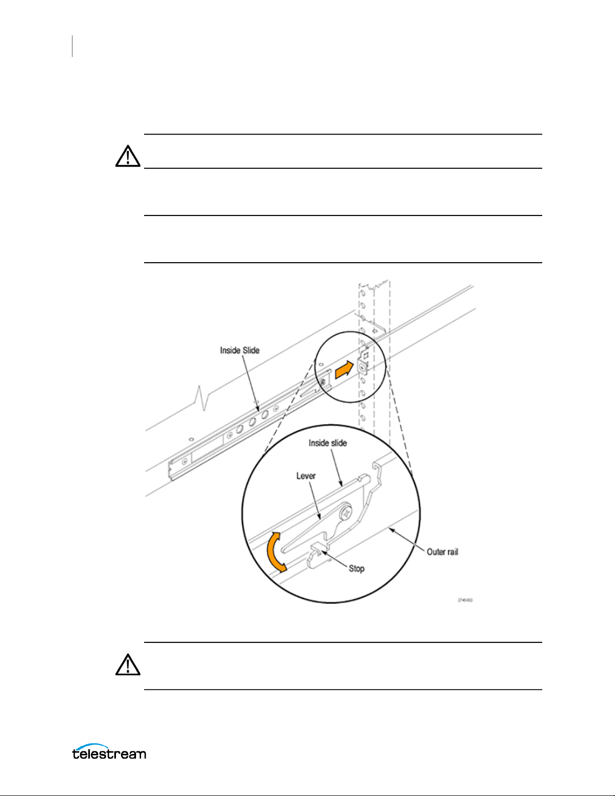
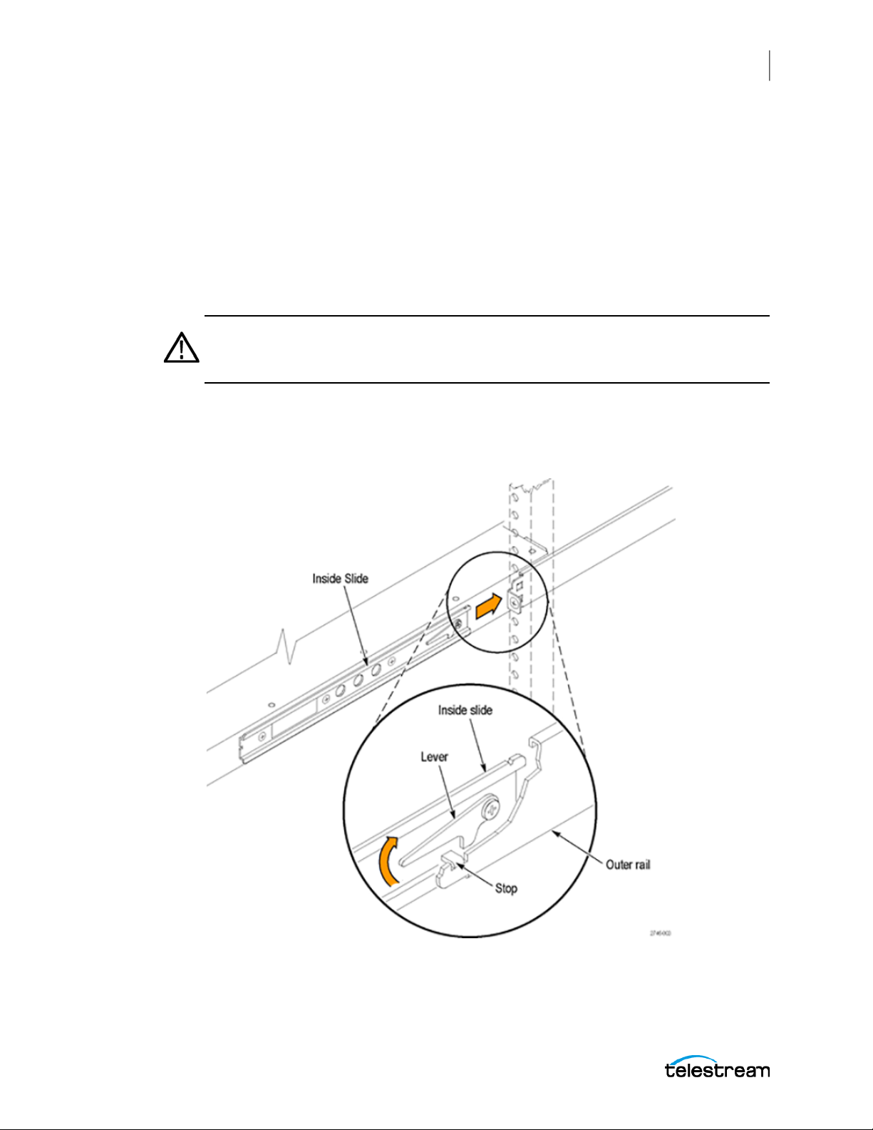
1. Insert the instrument left and right slides into the ends of the rack rails while tilting
the long handle of each lever upward.
Note: Be sure to insert the instrument slides inside the inner rack rails. You might
need to tilt rear of the instrument up or down at a slight angle to fit the slides into the
rails.
2. Push the instrument into the rack until it stops.
CAUTION: To prevent damage to the instrument and rackmount, do not force
the instrument into the rack if it does not slide smoothly. The rails assembly
might need to be adjusted to resolve the problem.
SPG9000 User Manual
Page 33
Instrument Installation
Rackmount Slides and Rails
3. Retighten any loose screws and push the instrument all the way into the rack. If the
tracks do not slide smoothly, readjust the rail assemblies.
4. When adjusting is completed, tighten all rail assembly 10-32 screws.
5. If the instrument has knob screws on the front corners, tighten them so they are
secured in the rack.
Remove Instrument from Rack
This procedure describes how to remove the instrument from the equipment rack.
WARNING: To prevent injury when removing the product from the rack, do not
forcefully and abruptly pull the product from the rack. Pull with the minimum
force required to move the instrument with a consistent, even motion.
1. Loosen the knob screws, if present, at the front of the instrument.
2. Gently pull the instrument out until you can reach the levers on the inside slides.
3. Tilt both lever handles upward at the same time to clear the stops.
33
4. Pull the instrument past the stops and out of the rack.
SPG9000 User Manual
Page 34

34
Instrument Installation
Power Connection
Power Connection
The instrument operates from a single-phase power source with the neutral conductor
at or near earth ground. The line conductor is fused for over-current protection. A
protective ground connection through the grounding conductor in the locking power
cord is essential for safe operation.
With option SPG9000-SPW, a single power supply module is installed. With Option
SPG9000-DPW, a second, hot-swappable, redundant (backup) power supply module is
also installed. When two power supply modules are installed in the instrument, one is
configured to be the primary supply and the other is configured to be the backup
supply. In the event that the primary supply fails, the backup supply automatically
provides power to maintain instrument operation. See Power Supply Monitoring and
Replacement about how to operate the instrument with two power supplies.
WARNING: Injury or death can occur as the result of electrical shock. To avoid
electrical shock, do not connect power to the instrument when the top cover is
off. There are dangerous potentials present on the power supply circuit boards
when the power cord is connected.
Disconnect the power cord from a power supply module before you remove the
module from the instrument. Also, do not connect a power cord to a power
supply module while the module is not installed in the instrument. There are
dangerous high voltages on the module when the power cord is connected.
Power Characteristics
AC power source
Rating voltage 100 V to 240 V
Frequency 50 or 60 Hz
Typical power 130 VA
Maximum
power
Surge current,
typical
WARNING: To reduce the risk of fire and shock, ensure the
mains supply voltage fluctuations do not exceed 10% of
the operating voltage range.
180 VA
20 a peak (25 °C) for ≤ 5 lines cycles, after the instrument has
been turned off for at least 30 seconds.
Inrush current,
typical
10 A RMS half cycle at initial turn on according to
EN55103-1:2009 Annex B.
SPG9000 User Manual
Page 35

CAUTION: The instrument does not have a power switch. When you connect the
power cable to the AC line connector, the instrument powers on.
Do not install or remove a power supply module when a power cord is attached
to that module.
Connect Power
Connect the power cable to the instrument first and then connect it to the AC power
source. Connecting the power cable causes the instrument to power on. If there is a
backup power supply (option SPG9000-DPW), connect the second power cable to the
instrument and then connect it to the AC power source.
After the instrument boots up and initializes, check that the FAULT indicator on the
front panel is not illuminated and no faults are reported on the instrument display. If
the FAULT indicator is illuminated, take the appropriate action.
Instrument Installation
Power Connection
35
Each power supply module has an LED (labeled STATUS) visible on the rear panel that
mirrors the corresponding PWR indicator on the front panel. Under normal conditions,
the LED for the active power supply is bright green and the LED for the backup power
supply is dim green. See FAULT and PWR 1 and PWR 2 for descriptions of the FAULT and
PWR indicators.
SPG9000 User Manual
Page 36
36
Instrument Installation
Rear Panel Connectors
Rear Panel Connectors
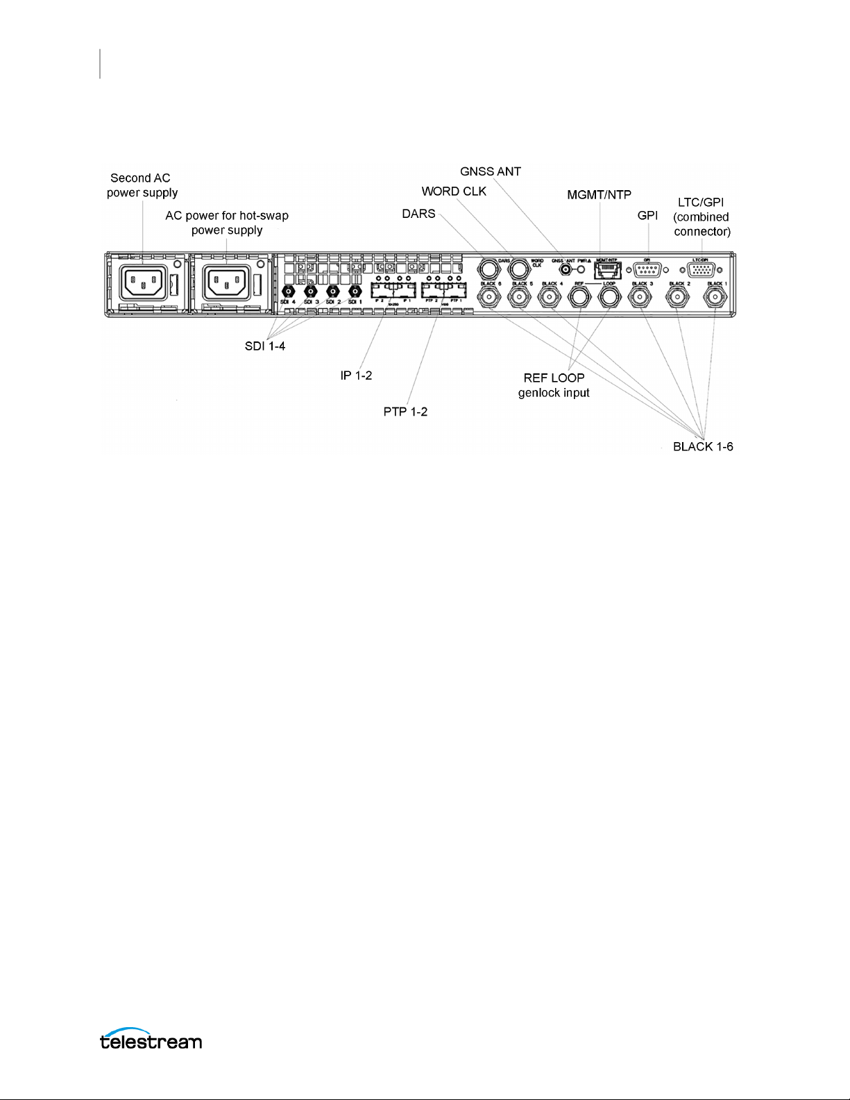
The descriptions of the connectors start with the base outputs on the right and move
to the optional outputs on the left.
LTC/GPI Connector
The LTC/GPI connector is a 15-pin, D-sub connector (DE-15 socket) that includes both
Linear Time Code (LTC) input and outputs, and a subset (3 inputs and 2 outputs) of the
General Purpose Interface. See Linear Time Code Input and Outputs.
A breakout cable is available for this connector with XLR connectors for the four LTC
outputs and BNC connectors for the GPI input (1 only) and outputs (1-2 only). It can be
ordered as option SPG9000-XLR at the same time as the base SPG9000 purchase or as
SPG9000-ACC-XLR, a standalone accessory purchased later.
In addition, the pin assignments were selected so a standard RGBHV cable can be used
for a subset of signals. These cables have been used to connect VGA computer output
to the component video inputs of a CRT monitor, with a DE-15-pin connector at one
end and five BNC connectors at the other end.
SPG9000 User Manual
Page 37

Instrument Installation
Rear Panel Connectors
The pin assignments for the connector are shown, with the RGBHV BNC connector
shown if available:
Pin Function RGBHV Cable Diagram
1 GPI output 1 Red BNC
2 GPI output 2 Green BNC
3 GPI input 1 Blue BNC
4 GPI input 2
5 LTC 4 negative
6 Ground Ground
7 LTC 3 negative Ground
8 LTC 2 negative Ground
9 Ground
10 LTC 1 negative Ground
37
11 GPI input 3
12 LTC 3 positive
13 LTC 2 positive H BNC
14 LTC 1 positive V BNC
15 LTC 4 positive
GPI Connector
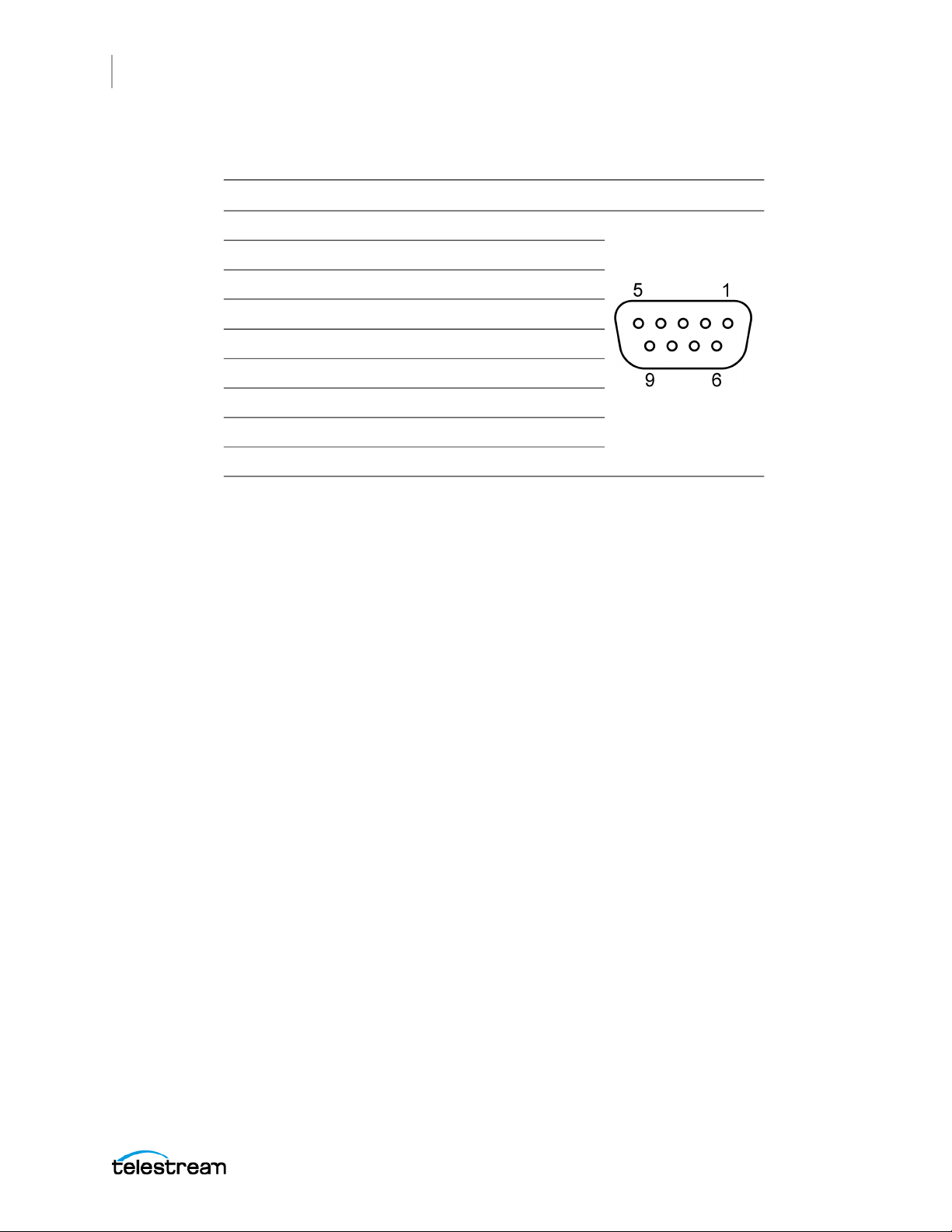
The General Purpose Interface (GPI) connector is a 9-pin, D-sub connector (DE-09
socket) reserved for future use. The GPI includes four ground closure inputs and three
ground closure outputs.
SPG9000 User Manual
Page 38
38
Instrument Installation
Rear Panel Connectors
The pin assignments for the connector are:
Pin Function Diagram
1 Ground
2 GPI output 1
3 GPI output 2
4 GPI input 1
5 +5 V (1 kΩ source resistance, limited current)
6 GPI output 3
7 GPI input 4
8 GPI input 3
9 GPI input 2
MGMT/NTP Port
Use the Management/NTP port to connect to your local Ethernet network. You can
control the instrument remotely through the port to connect to the web-based user
interface or the web services API.
This network interface will also be used for NTP (Network Time Protocol) messages in a
future firmware release.
See Management Network Interface.
GNSS ANT Connector
With option SPG9000-GNSS, the GNSS antenna connector allows you to synchronize
the instrument timing to one or more GNSS (Global Navigation Satellite Systems). The
integrated receiver supports the global GPS (United States), GLONASS (Russia), BeiDou
(China), and Galileo (European Union) systems, and the regional QZSS (Japan) system.
You must connect a GNSS antenna to the instrument to use this functionality. The GNSS
antenna input must meet specific requirements. See Antenna Requirements.
You can enable this connector to provide 3.3 V or 5 V DC power to the antenna, or
disable power if the antenna is externally powered. When the connector is configured
to provide power to the antenna, the rear-panel GNSS ANT indicator is illuminated:
● Blinks green to indicate an open circuit. This occurs if no antenna is connected or if
the current load is less than expected because a splitter or DC block is being used.
● Displays solid red if the connected antenna is shorted.
● Displays solid green if the current load of the antenna is within the nominal range.
See GNSS Receiver Settings.
SPG9000 User Manual
Page 39

WORD CLK Output Connector
The Word Clock connector outputs a 48 kHz word clock signal.
DARS Output Connector
The DARS connector outputs an AES11 DARS (Digital Audio Reference Signal) signal.
BLACK 1–6 Output Connectors
The six BNC connectors labeled BLACK 1 to BLACK 6 are used to each output a black
burst (NTSC or PAL), HD tri-level sync, 1 PPS (pulse-per-second) or 10 MHz CW
(continuous wave) signal.
Note: The 10 MHz CW signal is only available on the BLACK 3-6 outputs.
You can set the format and timing of the six black outputs independently and enable
VITC to be applied to the output signal. For HD tri-level sync signals, the BLACK 1-3 and
BLACK 4-6 outputs are independent groups. Within each group, any of the three
outputs configured to a tri-level format must have all integer (25, 24, 30, etc.) or noninteger (29.97, 23.98, etc.) frame rates. See Black Outputs.
Instrument Installation
Rear Panel Connectors
39
REF LOOP Input Connectors
Use the Reference Loop input loop-through connectors for an external reference signal
(genlock input), which can be an NTSC/PAL black burst or HDTV tri-level sync signal.
The reference input requires proper external termination. The signal can connect to
other devices through the loop connection; however, the signal must be terminated
eventually, either on the instrument or at the other device. See Genlock Reference.
PTP 1-2 Ports
With option SPG9000-PTP, the PTP 1 and PTP 2 ports are enabled. Each port
corresponds to an independent PTP instance. Two SFP+ slots are provided for use with
SFP modules that can operate at 10 Gbps or 1 Gbps line speed depending on the SFP
type.
These SFP modules are available as accessory options:
SPG9000-SFP-1GESR 1 G (gigabit) Ethernet, short reach, 850 nm SFP transceiver
module
SPG9000-SFP-10GESR 10 G Ethernet, short reach, 850 nm SFP+ transceiver module
SPG9000-SFP-10GELR 10 G Ethernet, long reach, 1310 nm SFP+ transceiver module
See PTP Configuration.
SPG9000 User Manual
Page 40

40
Instrument Installation
Rear Panel Connectors
IP 1-2 Ports
These two Ethernet ports have LEDs that show the current link status. The left LED is
green when the link is up and flickers when there is network activity. The right LED is
green when the interface operates at the 10 Gbps line rate, but it is not on when the
interface operates at the 1 Gbps line rate.
With option SPG9000-IP, the IP 1 and IP 2 ports are enabled for generation of ST 2110 IP
streams of video, audio, and data test signals. Two SFP28 slots are provided for use with
SFP modules that can operate at 25 Gbps or 10 Gbps line speed depending on the SFP
type.
These SFP modules are available as accessory options:
SPG9000-SFP-10GESR 10 G (gigabit) Ethernet, short reach, 850 nm SFP+ transceiver
module
SPG9000-SFP-10GELR 10 G Ethernet long reach, 1310 nm SFP+ transceiver module
SPG9000-SFP-25GESR 25 G Ethernet short reach, 850 nm SFP28 transceiver module
SPG9000-SFP-25GELR 25 G Ethernet, long reach, 1310 nm SFP28 transceiver
module
Option SPG9000-IP will be available in a future firmware update.
SDI 1-4 Output Connectors
With option SPG9000-SDI, the SDI 1 to SDI 4 outputs are enabled for test signal
generation through HD-BNC connectors. Each output has an independent line rate of
SD-SDI (270 Mbps), HD-SDI (1.5 Gbps and 3 Gbps), or UHD (6G-SDI and 12G-SDI).
Option SPG9000-SDI will be available in a future firmware update.
SPG9000 User Manual
Page 41
SFP Module Installation
This section explains how to install and remove an SFP module from an SPG9000.
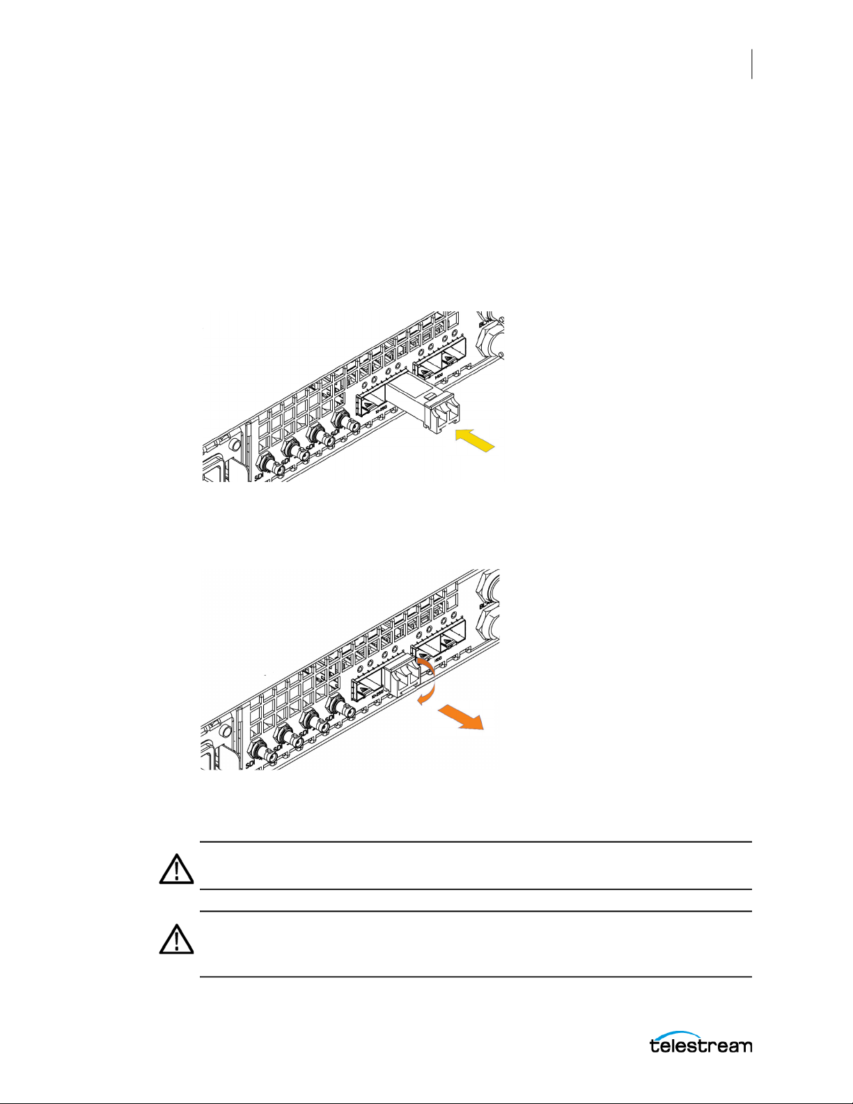
Install SFP Module
1. Remove the protective plug from the SFP connector.
2. Insert the SFP module into the PTP connector on the rear-panel of the instrument
as shown. The module latches into place when fully inserted.
Instrument Installation
SFP Module Installation
41
Remove SFP Module
Pull down on the latch and pull the module out of the PTP connector as shown.
The SFP module should be removed from the generator while the instrument is being
transported.
CAUTION: To prevent damage to the SFP modules, remove the SFP modules
before transporting the SPG instrument.
CAUTION: To prevent static damage to the SFP modules, if you remove the SFP
modules from the instrument, always transport the SFP modules in an anti-static
bag or container.
SPG9000 User Manual
Page 42

42
Instrument Installation
SFP Module Installation
CAUTION: To prevent dust from contaminating the SFP module, use its cover
when the SFP is not in use. If SPF modules or fiber optic cable have been left
exposed, we recommend cleaning it before use. This is especially important on
the long-reach, single-mode SFP modules and fiber.
SPG9000 User Manual
Page 43

GNSS Antenna Installation
If your instrument has option SPG9000-GNSS enabled, you need to connect a GNSS
antenna and check the main oscillator calibration before you put the instrument into
service.
If you ordered SPG9000-ACC-ANT, you received a GNSS rooftop antenna (5.0 VDC, dualband (L1 and L5), type-N connector) that is matched with the internal GNSS receiver.
After installation, see GNSS Receiver Settings.
Antenna Requirements
The instrument requires an external antenna to receive GNSS signals from satellites.
You must set up an antenna system to provide the GNSS signal as an input to the
instrument. You can configure the instrument to provide 3.3 V or 5 V DC power for the
antenna.
WARNING: Prevent risk of shock or fire by ensuring that the GNSS antenna is
protected from lightning strikes when it is mounted outside a building or facility.
The instrument does not have isolation protection from lightning, so the facility
installation must provide suitable protection for the GNSS antenna external to
the instrument and surge suppression for the cable. Failure to use appropriate
precautions can result in injury or death. It is important the antenna and cable
installation complies with all regulations for the location in which it is installed.
Instrument Installation
GNSS Antenna Installation
43
CAUTION: To avoid antenna damage, do not turn on the DC antenna power until
you know that the antenna is designed to handle the selected voltage. Antenna
damage can occur if the antenna is not designed to handle the voltage you
select.
Note: The frequencies for the different GNSS systems are slightly different from each
other. Be sure to choose an antenna that supports all of the satellite constellations you
intend to use. We recommend you use an antenna, amplifiers, and splitters that can
receive signals from multiple GNSS systems and frequency bands. This allows the
instrument timing to be more stable because a GNSS antenna can communicate with
more satellites.
When a GNSS signal is first connected to the antenna input on the instrument, it can
take several minutes for the signal quality to reach its nominal potential. How long that
takes depends on such things as antenna site, cable plant design, and available
satellites. Excluding those variables, the typical time to acquire satellites and achieve
specified stability with a good satellite signal, known position, and a warmed up
instrument, is two minutes.
SPG9000 User Manual
Page 44
44
Instrument Installation
GNSS Antenna Installation
Antenna Systems
Antenna systems vary depending on the operating environment and on safety and
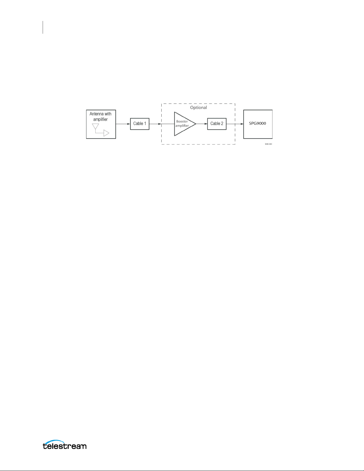
regulatory requirements. A simplified GNSS antenna and cable block diagram is shown
to help you with planning and understanding the trade-offs of one setup versus
another.
A GNSS- specific antenna with amplifier provides sufficient gain to drive a reasonable
length of cable, and provides filtering to reject signals at other frequencies. A typical
example for GNSS signals is the Protempis Bullet™ 720, 35±3 dB, 5 V antenna.
In a simple system without the optional booster, Cable 1 connects the antenna to the
instrument. The length of this cable is limited by its attenuation at the carrier frequency
(L1: 1559~1610 MHz, L5: 1164~1214 MHz). The instrument should have a signal that is
18 dB or greater above the ambient level. For example, for a 35 dB antenna, the allowed
loss is 17 dB.
Antenna Location
It is important that the GNSS antenna location has a clear view of a large part of the sky.
Because GNSS satellites are constantly orbiting the earth, they can be in any direction
at a given time. If part of the sky is blocked by buildings, trees, mountains, etc., then
fewer satellites are visible. It is also possible to get reflected signals that come by a
longer path than expected, which can degrade timing accuracy and stability. When
evaluating a site, it is important to monitor it over several days and with a variety of
weather conditions present.
This antenna information is not intended to cover all aspects of the antenna system
design. Important topics that were not covered include items like lightening protection
and drip loops. For information about the cable plant design in your system, contact
the appropriate person or group in your organization, or contract with a qualified
installer.
Cables
Attenuation varies significantly depending on cable type. Cable loss is about
13 dB/100 ft for a miniature coaxial cable like the Belden 1855, while for a RG 1 style like
the Belden 7731, the loss is only 5.5 dB/100 ft. This correlates to an allowable length of
130 ft for the small cable, to over 300 ft for the larger cable.
A booster amplifier can be added if more length is needed, as shown in the optional
block in the signal path system. The booster amplifier should be closer to the antenna
than to the SPG9000.
SPG9000 User Manual
Page 45

Instrument Installation
GNSS Antenna Installation
If a 20 dB amplifier is added, then 20 dB more cable loss can be accommodated. This
equates to another 150 ft of small coaxial cable, or 360 ft of large coaxial.
Although the GNSS input and most of the other components are 50 Ω, either 50 Ω or
75 Ω cables can be used in most installations. The reflections from the impedance
mismatch will not cause significant changes in the system because the signal is narrow
band and the cable loss is usually many decibels. However, you should not mix short
cable lengths of different impedances, as this might create reflections with the
potential to cause signal degradation.
Amplification
The instrument provides either 3.3 V or 5 V DC power to drive the amplified antenna
and booster amplifier. The power is carried on the same coaxial cable as the GNSS
signal, and can be turned off if the antenna is powered by a separate supply. When you
are designing the antenna system, check the voltage and current requirements of the
components to insure compatibility.
The location of the booster amplifier is important. It needs to be before the second
length of cable, shown in the simplified GNSS antenna and cable block diagram.
45
If the booster amplifier is placed just before the instrument, then the signal has been
attenuated too far and the output might be noisy. If you cannot put the optional
booster amplifier in the middle of a long run of cable, then put it near the antenna
rather than near the instrument end.
For more complex systems, a variety of booster amplifiers, powered and passive
splitters, DC blocks, and filters are available from a number of vendors.
SPG9000 User Manual
Page 46

46
System Operation
System Operation
This section describes the basic operation of the SPG9000. This includes descriptions of
the front panel of the SPG9000 and how to navigate the on-screen menus. There are
also details of how to use the web interface: how to log in, information in the tabs, and
how to understand the available information. This section also explains how to control
the instrument through API. Finally this section explains how to create, save, and recall
presets.
SPG9000 User Manual
Page 47
Front Panel Interface
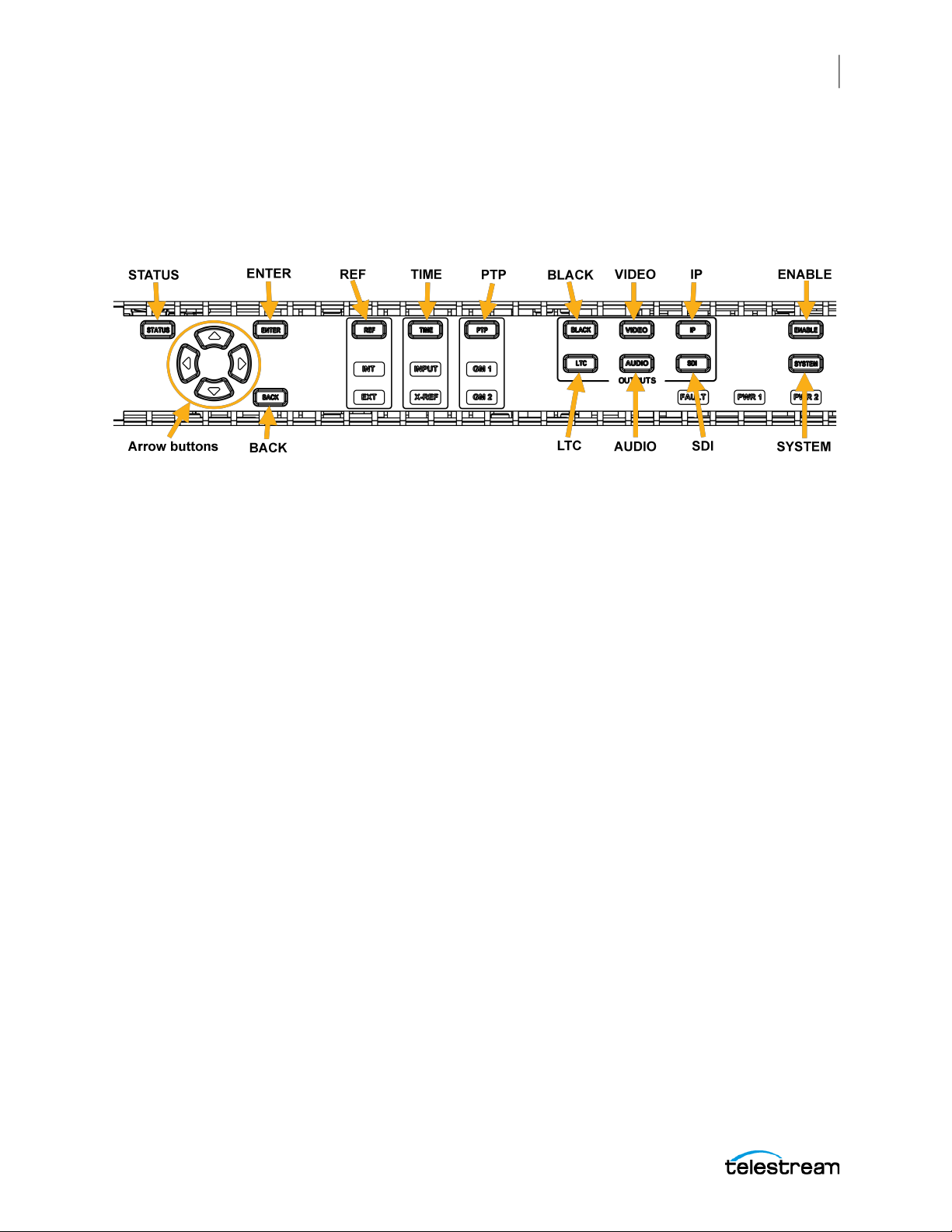
This section provides information about operating the instrument using the frontpanel buttons and display. These menus and selections are similar to those on the web
interface.
Front Panel Layout
System Operation
Front Panel Interface
47
The SPG9000 front panel includes a color display for configuration menus and status
messages, and a set of buttons for accessing and navigating these menus.
STATUS: Press to view the current status of the instrument, such as the state of the
reference source, time-of-day, GNSS signal, and PTP instances. See System Status and
Monitoring.
ENTER: Press to accept the selected option.
Arrow buttons: Use the
available menus, use the
options for the current menu.
BACK: Press to return to a previous menu or exit Edit Mode.
REF: Press to configure the reference source and GNSS receiver parameters. See
Reference and Time Sources.
TIME: Press to configure the time-of-day source and options for daylight saving time,
leap second, and daily jam sync management. See Reference and Time Sources.
PTP: Press to configure the two PTP instances. See PTP Operation.
BLACK: Press to configure the six black outputs. See Black Outputs.
LTC: Press to configure the four LTC outputs (or one input and three outputs). See Linear
Time Code Input and Outputs.
(up) and (down) buttons to scroll through the list of
(left), and (right) buttons to view the list of available
VIDEO, AUDIO, IP, and SDI: These are reserved for future test-signal generation
functions.
ENABLE: Press and hold to enable and disable the front-panel interface. See Front Panel
Disable and Enable.
SPG9000 User Manual
Page 48

48
System Operation
Front Panel Interface
SYSTEM: Press to configure system-wide parameters such as presets, network
interfaces, passwords, and power supplies.
Front Panel Disable and Enable
Access to the front-panel interface can be configured to end after a period of idle time.
See Front Panel Settings.
Disable Front-panel Interface
Press-and-hold ENABLE for 2 seconds. The display backlight is dimmer when the
interface is disabled. When the front-panel interface is disabled, pressing any front
panel button does not have an effect, except the ENABLE button is
illuminated as a reminder that the front panel is currently disabled.
Enable Front-panel Interface
Press-and-hold ENABLE for 4-5 seconds. The display backlight is brighter when the
interface is enabled.
Menu System
The SPG9000 front-panel interface is organized as a set of menus. Each of the front
panel menu buttons is associated with one of the menu lists. For example, press the REF
button to open the REFERENCE menu list. The top line of the display shows the name of
the current menu in its hierarchical structure. For example, the REFERENCE : GENLOCK :
TIMING menu is a third-level menu under the REFERENCE menu list.
1. Press REF to open the REFERENCE menu.
2. Press the
Note: Menus are organized in a circular structure; if you press the same arrow
repeatedly, you will view all available menus and return to your original starting menu.
3. When the REFERENCE : GENLOCK menu is displayed, press ENTER.
4. Repeat the process to find the TIMING submenu, and press ENTER.
Some buttons are associated with multiple outputs or ports. Press a menu button
repeatedly to cycle through the menus for each of the outputs. For example, press the
LTC button to cycle through the four menus for LTC 1 through LTC 4. Within any of these
menus, press the
output. The LTC 1 menu has six submenus: MODE, FORMAT, SOURCE, OFFSET, DELAY,
and OUTPUT LEVEL. The list of submenus is circular, meaning you can go directly from
or button to move between menus.
or button to cycle through the complete set of menus for that
SPG9000 User Manual
Page 49
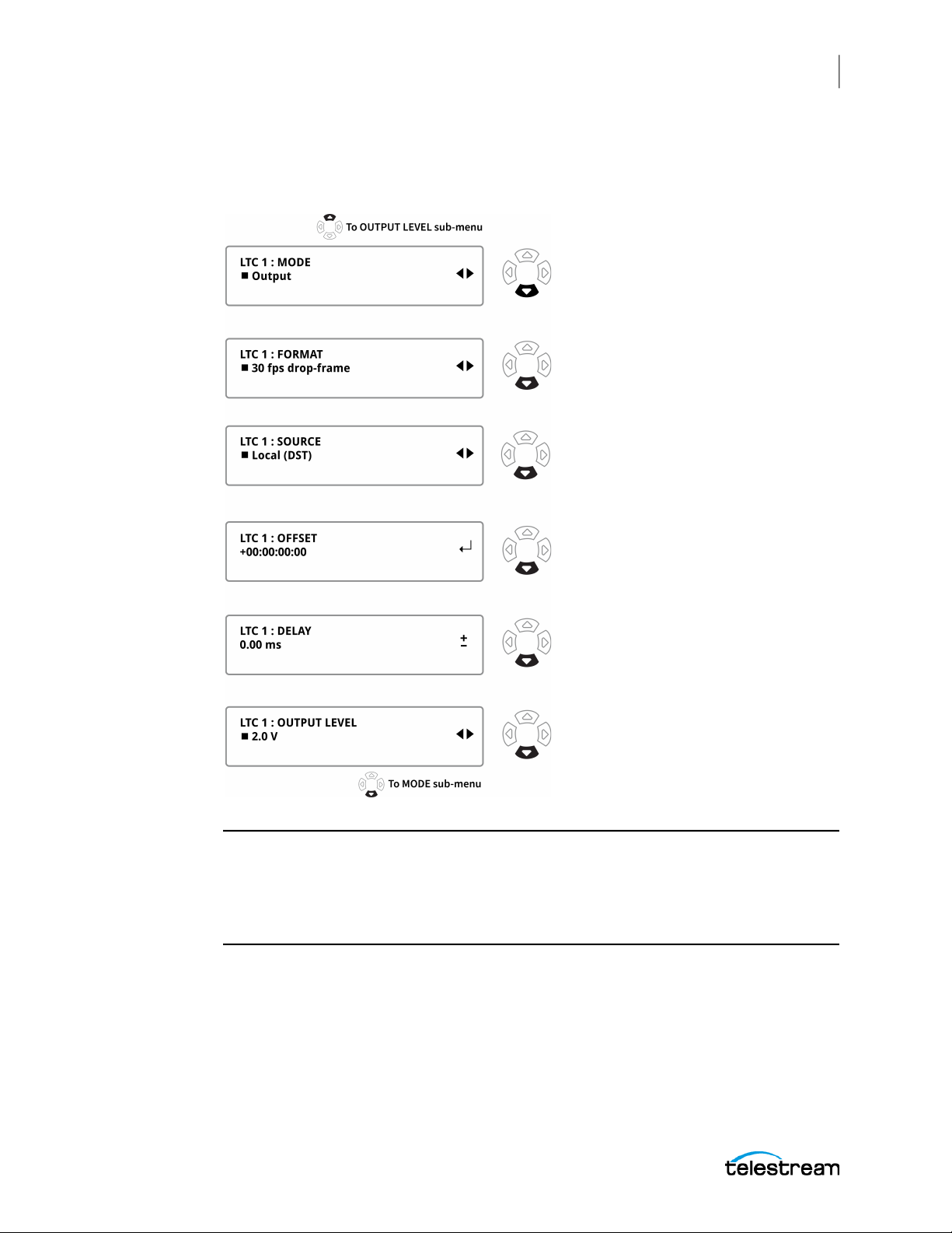
System Operation
Front Panel Interface
the first submenu (in this example MODE) to the last submenu (in this example
OUTPUT LEVEL) by pressing the
pressing the
button.
button, or from the last submenu to the first by
49
Note: Menus might be hidden if they are not applicable or available in the current
configuration settings. In this example, the MODE submenu is only available for LTC 1
because only LTC 1 can be configured as an input or as an output. When it is
configured as an input, the other five submenus (FORMAT through OUTPUT LEVEL) are
hidden because they are only applicable for LTC outputs.
Menu Operations
There are four kinds of menus used for making configuration changes and for viewing
the instrument status. Each menu type is indicated by a symbol displayed on the right
side of the second menu line.
SPG9000 User Manual
Page 50
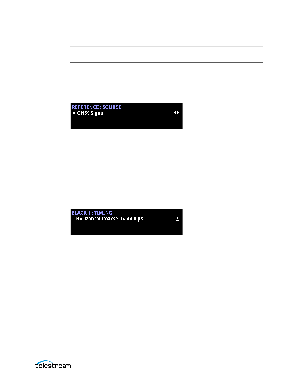
50
System Operation
Front Panel Interface
Note: In all menus, except in edit mode, the up and down arrows change the selected
menu.
Selection Menus
Selection menus are marked by the pair of left- and right-facing triangles on the right,
as shown in the example.
Use selection menus to choose one option from an available list. When the menu first
opens, the current setting is indicated by a square bullet symbol to the left of the item.
1. Press the
2. When the required option is displayed, press ENTER. The menu text blinks to
confirm the selection and the bullet indicates the new selection.
or button to cycle through the available options.
Adjustment Menus
Adjustment menus are marked by a plus-minus sign on the right, as shown in the
example.
Use these menus to make immediate adjustments to the configuration parameters.
● Press the right arrow to increase the parameter by the smallest increment available
(for example, 0.0185
● Press the left arrow to decrease the parameter by the smallest increment available.
● Press-and-hold the left or right arrow to increase or decrease the parameter until
the button is released.
● Press both left and right arrows at the same time to return the parameter to the
default value.
µs).
SPG9000 User Manual
Page 51
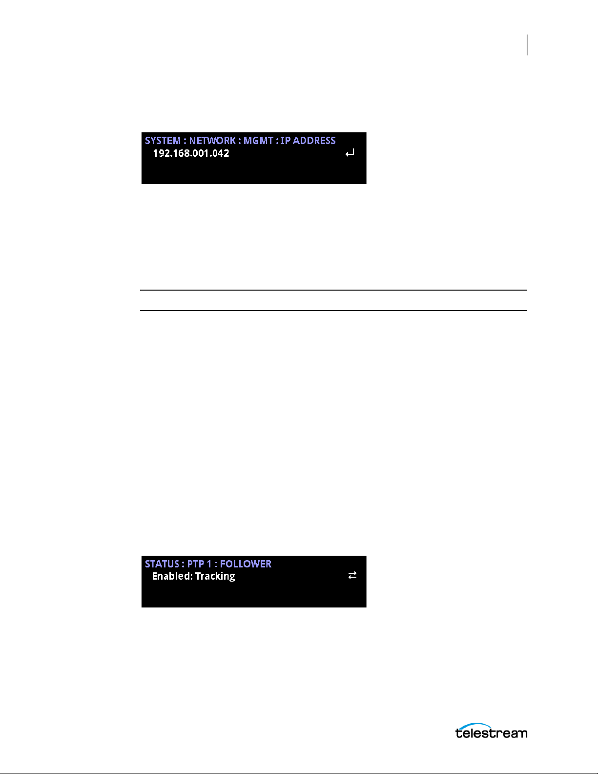
System Operation
Front Panel Interface
Edit Menus
Edit menus are marked by the carriage-return symbol, as shown in the example.
Use these menus to change editable strings like passwords, IP addresses, and
parameters with multiple fields. Edit menus are modal, which means the arrow buttons
have different behaviors when the menu is in edit mode from when the menu is in
navigation mode.
1. Press ENTER to switch the menu to edit mode, confirmed by an underline under the
first editable character, digit, or field.
Note: When in edit mode, you must press ENTER or BACK to leave.
51
2. Press the
or field.
3. Press the
digit, or field. For example, when editing an IP address, press the
cycle through the numeric digits 0-9.
4. When you have set the value for a character, digit, or field, press the
move to the next item and repeat.
5. When all changes have been made, exit edit mode:
or button to change to the next or previous editable character, digit,
or button to move through the available values for the character,
or button to
button to
○ To exit edit mode and accept the currently displayed values, press ENTER.
○ To exit edit mode and cancel the editing changes, press BACK.
Multiple-Page Menus
Multiple-page menus are used to display read-only status information, not for making
configuration changes. These menus are marked by a pair of arrows, facing opposite
directions, as shown in the example.
The arrows mark there is more information to be viewed by pressing the left or right
arrows.
Press a left or right arrow repeatedly to move though all available pages of information.
SPG9000 User Manual
Page 52

52
System Operation
Front Panel Interface
Front Panel Settings
There are several settings to change the appearance and behavior of the front panel
interface. These settings may only be changed from the front panel itself; you cannot
change these settings remotely from the web interface or the API. They are not saved in
preset files, but some settings are saved in the non-volatile memory of the instrument
so they are preserved when the system cycles power.
The table summarizes the menu structure that is accessed when you press the SYSTEM
button. Indentation indicates the menu hierarchy; for example, you need to access the
SYSTEM : FRONT PANEL submenus to configure the front panel settings. Other SYSTEM
menus are shown collapsed and with dim highlighting to show their position in the
menu list. For example, when you press the SYSTEM button, the first menu to be
displayed is SYSTEM : PRESET. Press the down arrow button three times to go to the
SYSTEM : FRONT PANEL menu. Press ENTER to go to the SYSTEM : FRONT PANEL :
TIMEOUT menu. Press the up or down arrow buttons to cycle between the three submenus (TIMEOUT, DISP BACKLIGHT, and BEEPER).
Menu lists like this are used in other sections of this document to help you move
through the front panel menu system.
SYSTEM :
PRESET :
INFO :
NETWORK :
FRONT PANEL :
TIMEOUT
DISP BACKLIGHT
BEEPER
WEB :
POWER SUPPLY :
FIRMWARE UPGRADE
CALIBRATE OVEN
DIAGNOSTICS
TIMEOUT
Select the idle time period before the front panel buttons are disabled. This feature can
be used to prevent accidental configuration changes. An operator must explicitly reenable the front panel interface to access any menus.
Select Disable if you never want the front panel interface to time out. See Front Panel
Disable and Enable.
CAUTION: We strongly recommend using the timeout function to keep the
display backlight at a low level when the front panel interface is not actively
being used, to maximize the life of the display backlight.
SPG9000 User Manual
Page 53

System Operation
Front Panel Interface
DISP BACKLIGHT
Select the brightness of the backlight for the front panel LCD. The display brightness
can be adjusted from a value of 1 (dim) to 8 (bright). When the front panel interface is
disabled, the display backlight brightness changes to the dimmest value (1) until it is
re-enabled and the selected brightness is restored.
BEEPER
Select Enable to permit the internal beeper to sound. The beeper emits a short chirping
sound every second when there is a hardware fault. See FAULT.
This setting is not saved in non-volatile memory. If the beeper is disabled, it re-enables
when power is cycled. This ensures that the hardware fault alarm is not unintentionally
ignored.
53
SPG9000 User Manual
Page 54

54
System Operation
Management Network Interface
Management Network Interface
The instrument has a 10/100/1000 BASE-T Ethernet port on the rear panel that is used
for management functions. You can remotely control the instrument through the web
interface or through the application programming interface (API), and system events
can be logged to a remote server from the management interface.
This section provides instructions for configuring the network parameters of the
management network interface.
Note: The management port can only be configured using the front panel user
interface.
Front Panel Menu for NETWORK
To use the front panel of the SPG9000 for this process, press SYSTEM and then select
the NETWORK option. See Menu Operations for details of using the front panel menus.
The table shows the submenus for the NETWORK menu.
SYSTEM :
PRESET :
INFO :
NETWORK :
MGMT :
DHCP
IP ADDRESS
SUBNET MASK
GATEWAY
MAC ADDRESS
HOSTNAME
DOMAIN NAME
PTP 1
PTP 2
FRONT PANEL :
WEB :
POWER SUPPLY :
FIRMWARE UPGRADE
CALIBRATE OVEN
DIAGNOSTICS
Configuration Settings for NETWORK
The NETWORK settings are used to configure all the Ethernet ports for the SPG9000,
including the management interface, the PTP ports, and the IP ports.
SPG9000 User Manual
Page 55

System Operation
Management Network Interface
MGMT
The MGMT submenu includes all the configuration settings for the management
network interface.
DHCP
Select Enable to use Dynamic Host Configuration Protocol (DHCP) on the management
interface. In this case, a DHCP server must be present on the network, and it assigns the
IPv4 address, subnet mask, and gateway address. If you enable DHCP, manual
configuration of those values is disabled but the values provided by the DHCP server
are displayed.
IP ADDRESS
Enter the four octets of the IPv4 address, in dotted decimal notation. An edit menu (see
Edit Menus) is used to enter the address, with three digits for each octet with leading
zeros if necessary. For example, an address of 192.168.1.50 would appear as
192.168.001.050 in this menu. If DHCP is enabled, the IPv4 address supplied by the
DHCP server is displayed instead and cannot be edited.
55
SUBNET MASK
Enter the four octets of the subnet mask, in dotted decimal notation. If DHCP is
enabled, the subnet mask supplied by the DHCP server is displayed instead and cannot
be edited.
GATEWAY
Enter the four octets of the gateway address for this subnet, in dotted decimal notation.
If DHCP is enabled, the gateway address supplied by the DHCP server is displayed
instead and cannot be edited.
MAC ADDRESS
This is a read-only menu that displays the physical (MAC) address of the management
port. The first three octets of a MAC address indicate an Organizationally Unique
Identifier (OUI), to help identify equipment on the network. The OUI for Telestream is
00-90-56, so the MAC addresses always begin with these three octets.
HOSTNAME
Enter the hostname portion of the fully qualified domain name (FQDN) for the
instrument. This name can be used to access the instrument instead of using its IP
address. Valid characters for the hostname include alphanumeric characters (A-Z, a-z,
and 0-9) and the hyphen character. The first character must be a letter or numeral.
The factory default hostname is "spg9000-s000000" where the last six digits represent
the numeric portion of the device's serial number. The serial number can be seen on a
sticker on the left side of the SPG9000, and appears on a label on the packaging box.
SPG9000 User Manual
Page 56

56
System Operation
Management Network Interface
DOMAIN NAME
Enter the domain name portion of the FQDN. Valid characters for the domain name
include alphanumeric characters (A-Z, a-z, and 0-9), the hyphen character, and the "dot"
character (to separate levels in the domain hierarchy). The first character must be a
letter or numeral. Do not include the leading or trailing "." character.
The factory default domain name is "telestream.net", so this must be changed to your
local domain name.
SPG9000 User Manual
Page 57
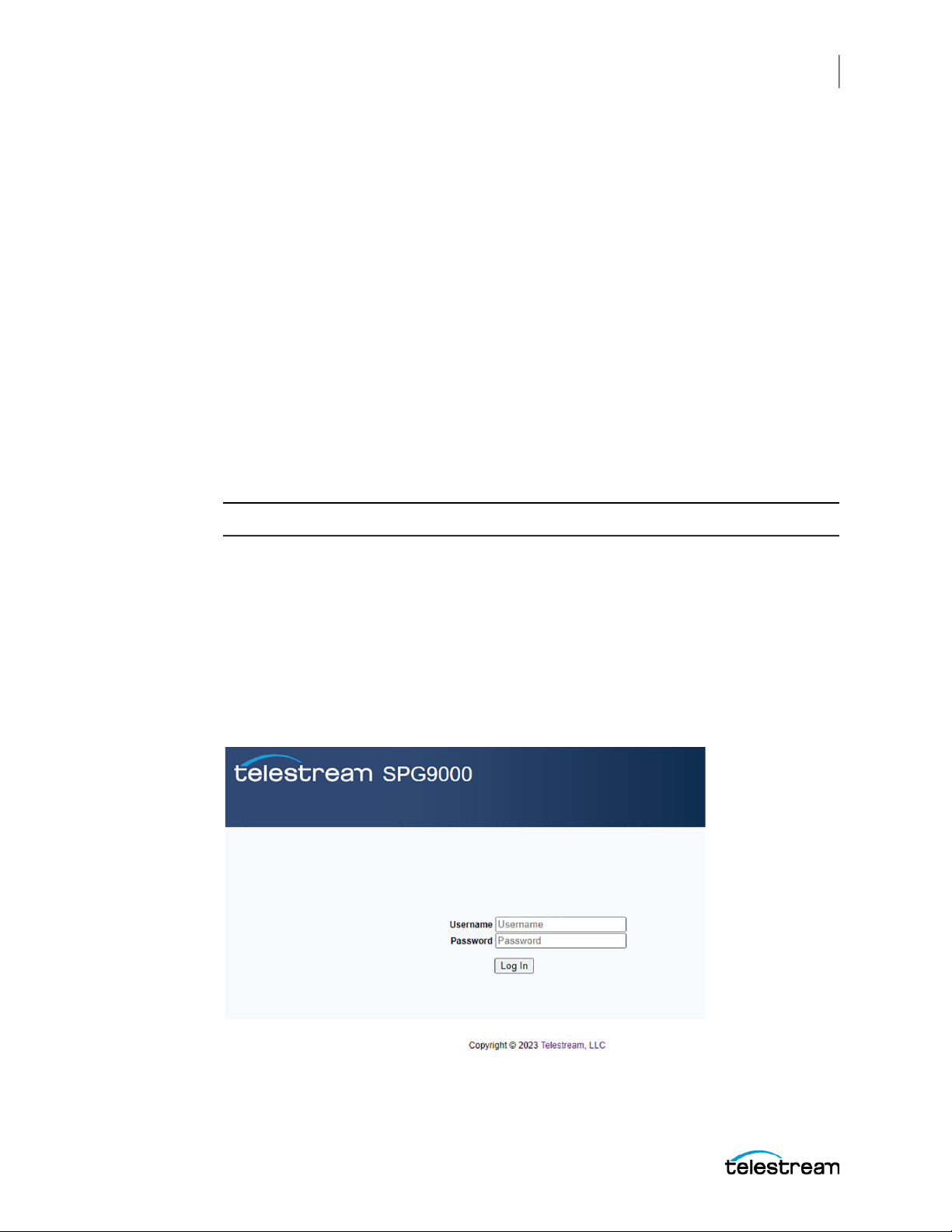
Web User Interface
After the management network interface has been configured, the SPG9000 can be
accessed through a web-based user interface, using any modern browser. The default
URL is:
http://hostname
where hostname is replaced with a fully qualified domain name of the SPG9000, or:
http://ip_address
where ip_address is replaced with the IP address of the management network interface.
Operational Considerations
We recommend a maximum of four simultaneous users be connected to the
instrument that is using the web interface. If more users are connected, it can result in
lower performance and inconsistent behavior.
System Operation
Web User Interface
57
Note: The web interface requires Javascript to run.
Web Interface for User Login and Access Control
When you first open the web interface URL, you will see a login page. The SPG9000 has
two built-in user accounts for web interface access: admin and operator. When you first
go to the web interface page, you will see a login prompt. The admin account has full
read-write control for all system settings. The operator account has a read-only view of
the instrument; the web interface shows status information but configuration settings
cannot be changed.
SPG9000 User Manual
Page 58

58
System Operation
Web User Interface
The default password for the admin account is "admin" and the default password for
the operator account is "operator". We recommend you change these passwords to a
unique value for each instrument. You can change both passwords from the SYSTEM :
WEB : ADMIN PASSWORD and SYSTEM : WEB : OPERATOR PASSWORD menus on the
front panel interface, or you can change the currently logged-in user's password from
the General Settings section on the System tab of the web interface.
Front Panel Menu for WEB
To use the front panel of the SPG9000 for this process, press SYSTEM and then select
the WEB option. See Menu Operations for details of using the front panel menus. The
table shows the submenus for the WEB menu.
SYSTEM :
PRESET :
INFO :
NETWORK :
FRONT PANEL :
WEB :
ADMIN PASSWORD
OPERATOR PASSWORD
POWER SUPPLY :
FIRMWARE UPGRADE
CALIBRATE OVEN
DIAGNOSTICS
SPG9000 User Manual
Page 59
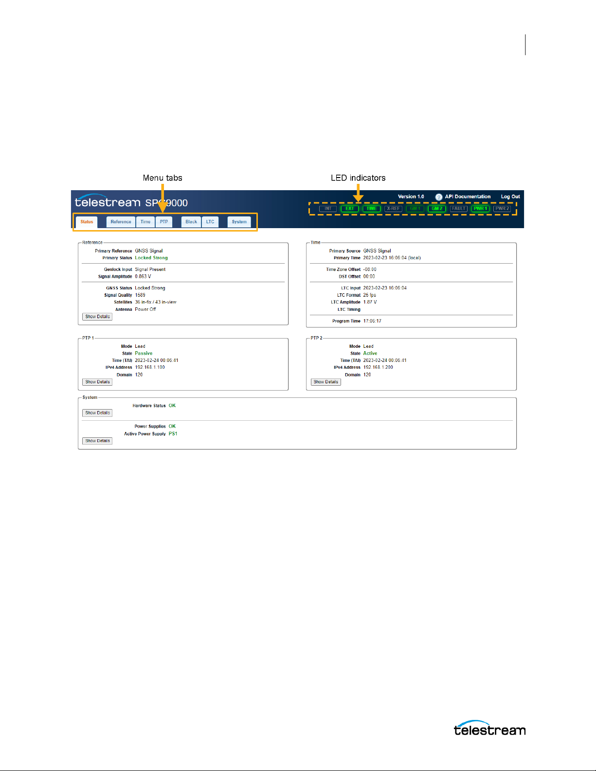
Elements of Web User Interface
The web interface for the SPG9000 is a single-page application that dynamically
updates based on current configuration and system state. The top banner (with a blue
background) is always present, but the main page body (with a white background)
depends on user navigation.
System Operation
Web User Interface
59
Menu tabs
The name of each tab corresponds to a specific button on the front panel, and items on
the tab are similar to the front panel menu system; see Front Panel Interface. On the web
page, select the tab to go to that item and see its menus.
Status
Select to observe the current operational status of the instrument. See System Status
and Monitoring.
Reference
Select to configure the current reference source (genlock input, GNSS signal, PTP
follower, or internal) and to configure the GNSS receiver (option SPG9000-GNSS
required). See Reference and Time Sources.
SPG9000 User Manual
Page 60

60
System Operation
Web User Interface
Time
Select to configure the time of day source (including any time zone offset), daylight
saving time parameters, leap second adjustments, daily jam sync schedule, and
program time. See Reference and Time Sources.
PTP
Select to configure the two PTP instances associated with the two SFP ports, labeled
PTP 1 and PTP 2. This tab is not present unless the SPG9000-PTP option is licensed. See
PTP Operation.
Black
Select to review and configure the six analog sync signal outputs. These are labeled
BLACK 1 through BLACK 6. See Black Outputs.
LTC
Select to configure the four linear time code (LTC) outputs, or three outputs and one
input. See Linear Time Code Input and Outputs.
System
Select to manage several system-wide settings, such as:
● Save and recall presets: see Presets.
● Update option licenses: see Licensed Features.
● Configure the web server, including security and authentication: see Secure Web
Interface.
● Configure system logging: see Syslog.
● Configure the network interfaces for the SFP ports: see Configuration Settings for
PTP Network Interfaces.
● Manage the power supply modules: see Power Supply Monitoring and Replacement.
LED indicators
The indicators are the same as those on the front of the instrument. See Indicators.
API Documentation
Select to open the SPG9000 HTTP API web page. See HTTP API.
Secure Web Interface
The SPG9000 integrated web server can use HTTPS instead of HTTP to provide a secure
web interface. This might be required by your organization cybersecurity requirements,
such as EBU R 143.
SPG9000 User Manual
Page 61
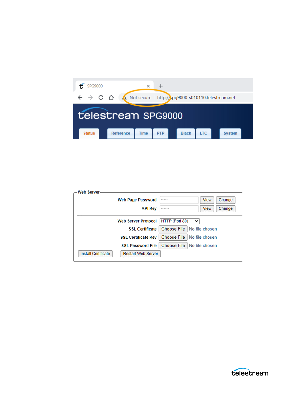
System Operation
Web User Interface
The factory configuration for the web interface is to use HTTP but you can install your
organization certificate files and use HTTPS.
Most browsers show the site status and protocols. For example, with plain HTTP, the
Chrome browser indicates the SPG9000 web interface is "Not secure":
Configure Web Server
61
To install new SSL certificate files and switch to HTTPS,
1. Click the System tab and open the General Settings section.
2. Go to the Web Server subsection.
Two or three SSL certificate files are needed to complete the installation. Your IT
organization should provide the files for your domain. Use the web interface to
select these files from a location on a local computer.
SSL Certificate: Choose the certificate file. This file should use the PEM format and
have a filename extension of .crt.
SSL Certificate Key: Choose the private key file. This file should use the PEM format
and have a filename extension of .key.
SSL Password File: Choose the password file. This file is optional and only needed
if the key file uses passphrases. The password file should have a filename extension
of .txt.
SPG9000 User Manual
Page 62
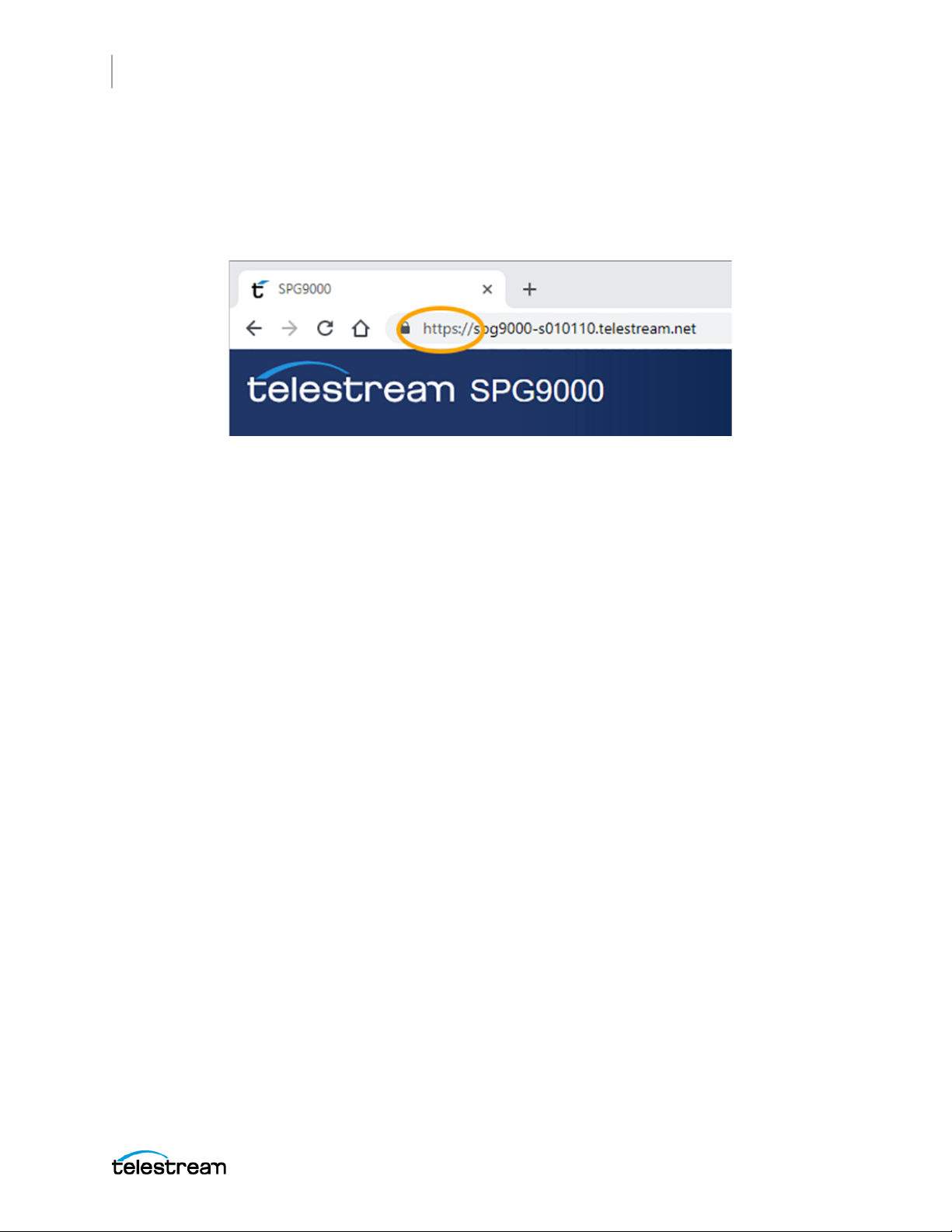
62
System Operation
Web User Interface
3. When the certificate, key, and optional password files have been selected, click
Install Certificate to upload the files to the SPG9000.
4. If the certificate files are installed successfully, select HTTPS (Port 443) from the
Web Server Protocol menu and click Restart Web Server. After the web server
restarts, the web page shows as secure.
SPG9000 User Manual
Page 63

Application Programming Interfaces
Application Programming Interfaces
The SPG9000 has multiple application programming interfaces (APIs) for remote access
to the instrument. Client-side applications, such as data visualization dashboards, can
use the APIs for system management and monitoring.
HTTP API
The primary API for the SPG9000 is based on Hypertext Transfer Protocol (HTTP)
messages with JavaScript Object Notation (JSON) text. This API style is commonly
referred to as a REST (Representational State Transfer) API. Strictly speaking, the
SPG9000 API is not RESTful, but the message formats are familiar to developers with
REST API experience.
Messages and Endpoints
The SPG9000 HTTP API uses three HTTP message types:
GET: Used to read status and/or configuration information from the SPG9000. The
GET message sent to the SPG9000 does not have a message body, but the normal
response from the SPG9000 (200 OK) includes a JSON object (content-type: application/json) including the requested values.
PUT: Used to set configuration parameters. The message body for the PUT message
must be a JSON object with the parameter to be updated. The SPG9000 accepts a
partial JSON object for PUT messages, so a subset of configuration parameters can
be changed while keeping other parameters unchanged.
POST: Used to command the SPG9000 to perform an internal operation.
System Operation
63
Endpoints are described in the documentation with a path such as "/system/status"
that corresponds to a complete URL:
where spg9000 is the hostname or the IP address of the system. The prefix /api/v1.0 is
required for every endpoint.
Note: If the SPG9000 web server has been configured to use HTTPS with an SSL
certificate (see Secure Web Interface), the API URL uses the protocol https://.
Authentication
The SPG9000 API requires all messages to be authenticated, similar to requiring a user
to log in with a password for the web interface. The header field X-API-Key must be
included in every HTTP request sent to the SPG9000. If this header field is missing or
does not match the user-configurable key value, the SPG9000 returns a response
message: 401 Unauthorized.
SPG9000 User Manual
http://spg9000/api/v1.0/system/status
Page 64
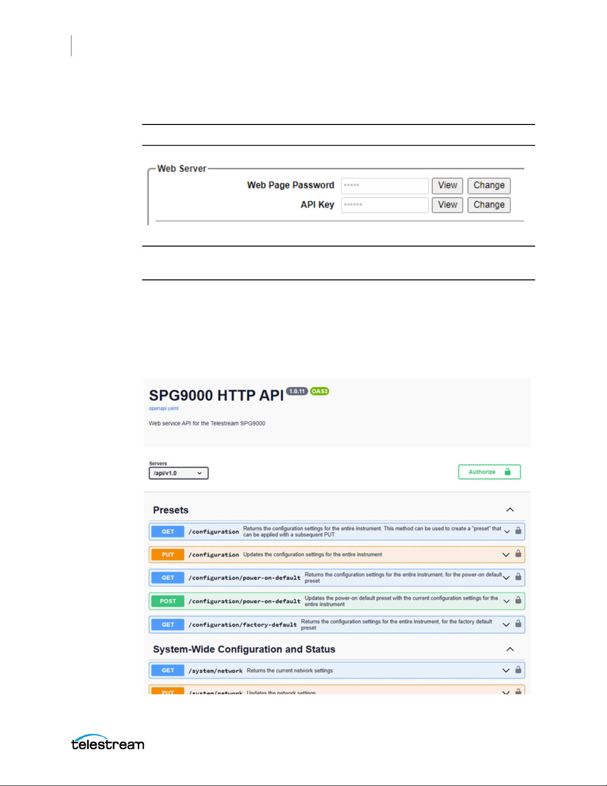
64
System Operation
Application Programming Interfaces
The factory default value for the API key is "apikey". This value can be changed at the
web interface, in the General Settings section of the System tab.
Note: You must be logged in as the admin user to view or change the API key.
Note: We recommend you change this value to a strong password, and do not share
the key outside your organization.
API Documentation
Documentation for the HTTP API is available in the SPG9000 web interface. In the top
banner, select API Documentation.
A new browser window appears for the documentation page.
SPG9000 User Manual
Page 65

System Operation
Application Programming Interfaces
The complete set of available messages is organized into categories on the
documentation page:
Presets: Messages with an endpoint starting with /configuration are used to
manage the configuration settings for any part of the entire instrument. See Presets.
System-Wide Configuration and Status: Messages with an endpoint starting with
/system correspond to configuration settings found on the System tab of the web
interface or the SYSTEM menu, and to status information found on the Status tab or
STATUS menu.
Reference and Time: Messages with an endpoint starting with /reference are used
to manage the configuration settings of the frequency and time reference sources
of the instrument, and to get the current status of all available reference sources.
PTP: Messages with an endpoint starting with /ptp are used to manage the two
PTP instances corresponding to the PTP 1 and PTP 2 ports. The option SPG9000-PTP
is required for this feature. The /ptp messages in the API are directly based on the
SMPTE RP 2059-15 YANG data model for PTP.
GNSS: Messages with an endpoint starting with /gnss are used to configure the
GNSS receiver and to get current status information about the received signals. The
option SPG9000-GNSS is required for this optional feature. Some of these messages
are based on the SMPTE RP 2059-15 YANG data model.
SMPTE RP 2059-15: Endpoints starting with /ptp-smpte, /grandmaster, or /rfc8173 are based on the SMPTE RP 2059-15 YANG data model. They are used to
access additional information not present in any of the /ptp endpoints, such as
values specific to the SMPTE ST 2059-2 PTP profile.
Black Outputs: Endpoints starting with /blacks are used to manage the configuration settings of the 6 analog sync (BLACK) outputs. See Black Outputs.
LTC Outputs: Messages with an endpoint starting with /ltc are used to manage the
configuration settings of the 4 Linear Time Code (LTC) outputs (or 3 outputs plus 1
input). See Linear Time Code Input and Outputs.
65
To view the details for a particular message, select the message name to open a panel
with example values and schema descriptions for the response body (GET messages)
and request body (PUT messages).
You can use the documentation to interactively send HTTP API messages to the
SPG9000 without requiring the use of external software:
1. Select Authorize at the top of the page and enter the API key.
2. Select Try it out.
3. You might have to enter a parameter for the URL; for example, for the GET /blacks/
4. For PUT messages, you also need to edit the JSON message body, starting with the
5. Select Execute to send the message to the SPG9000. The Responses section shows
SPG9000 User Manual
{output} message enter an output number to create the complete endpoint (that is,
/blacks/1 for the BLACK 1 output).
example provided.
the request and the server response.
Page 66

66
System Operation
Application Programming Interfaces
Syslog
The SPG9000 uses the standard syslog function to record log messages about system
status and events. Syslog messages can be directed to a remote server using the
management network interface. Syslog messages are not stored locally in the SPG9000
internal memory, so a remote server must be used to capture log messages.
Syslog uses a set of predefined facility codes to identify the event source. For example,
events related to security or authentication use the "auth" facility and events related to
the Linux kernel use the "kern" facility. Messages related to SPG9000 software
(including the PTP processes) use the "user" facility.
Syslog has eight defined severity levels. You can configure the threshold for reporting
events. For example, setting a threshold of Warning means that any Notice,
Informational, and Debug messages are not logged.
Severity Level Description
Emergency The system is unusable
Alert Action must be taken immediately
Critical Critical conditions
Error Error conditions
Warning Warning conditions
Notice Normal but significant conditions
Informational Informational messages
Debug Debug-level messages
Most messages logged by the SPG9000 use the Informational, Notice, Warning, or Error
severity levels.
Web Interface for System Logging
1. In the SPG9000 web interface, select the System tab.
2. Select the General Settings and find the System Logging section.
3. Make the necessary changes to the four parameters.
SPG9000 User Manual
Page 67
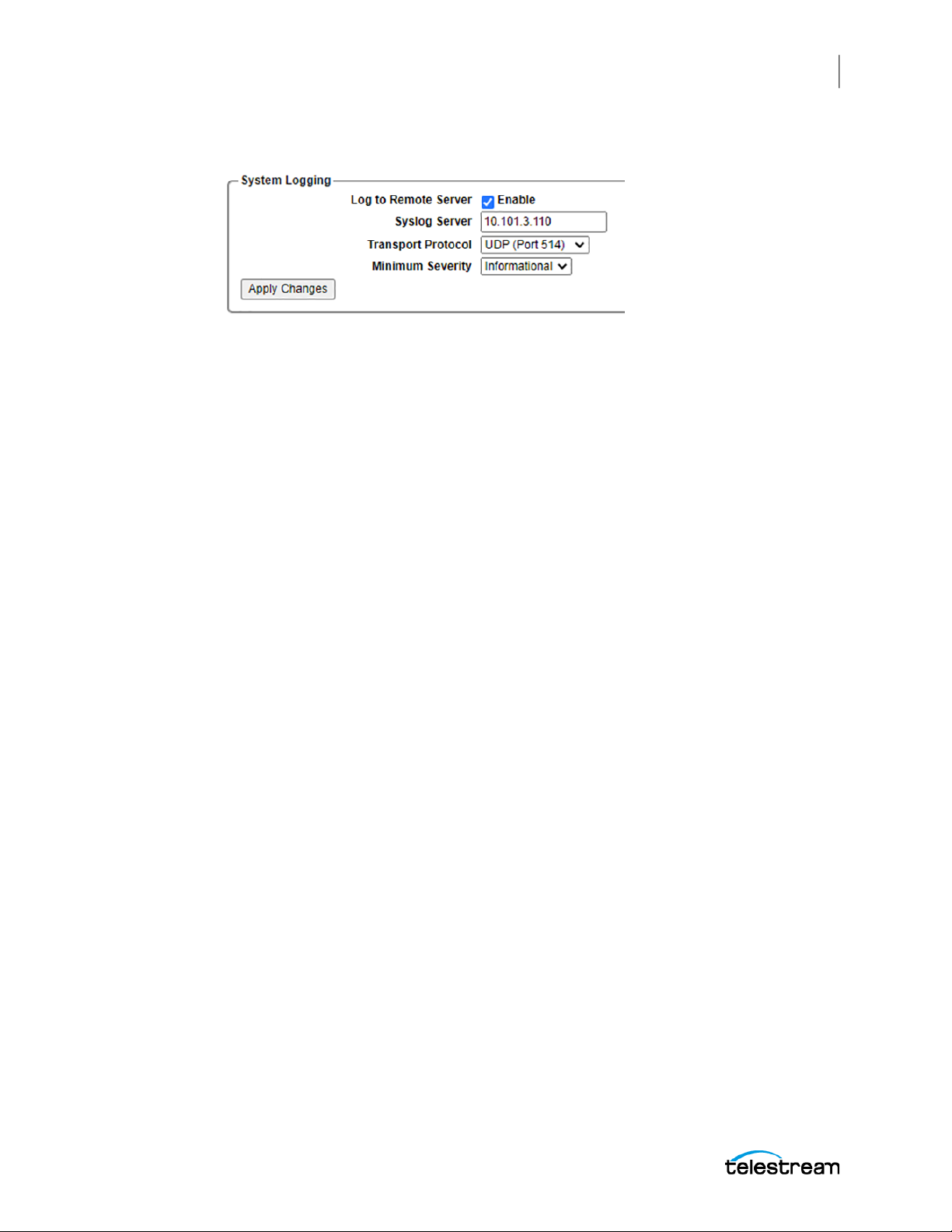
System Operation
Application Programming Interfaces
4. Select Apply Changes for the settings to take effect.
Configuration Settings for System Logging
Log to Remote Server
Select this box to enable logging. By default, logging is disabled.
Syslog Server
Enter the IP address of the remote server. Be sure that any firewall on the remote
computer is configured to permit syslog traffic to be received.
67
Transport Protocol
You can select UDP (port 514) or TCP (port 6514) for sending messages to the remote
server. The default is UDP, because it is a lightweight connectionless protocol with little
overhead. Select TCP for connection-oriented message transmission to the server.
Minimum Severity
You can select the minimum threshold for sending messages to the remote server. The
default value is Warning, which means that only Error and Warning level messages
would typically be logged. Severity levels of Emergency, Alert, and Critical are unlikely
to be observed, but they would be logged.
Message Format
Syslog messages are plain text but follow a specific format. In this example:
<13>Mar 16 12:34:56 spg9000-s012345 SPG9000[820]: Primary reference source is
now locked
the string is made up of five elements:
● The first field is the facility and severity level, “<13>” in this example. The decimal
number between the < and > brackets can be converted to binary digits (such as
00001101), and the 5 most significant bits (00001) indicate the facility (in this case
"user") and the 3 least significant bits (101) represent the severity level (in this case
"notice"). Many syslog servers automatically decode <13> as "user.notice" to make
logs easier to read.
SPG9000 User Manual
Page 68

68
System Operation
Application Programming Interfaces
● The second field is the date, "Mar 16 12:34:56" in this example. This time is the
system time of the instrument, which could differ from local time if the instrument
does not have a time zone or daylight saving time offset applied.
● The third field is the hostname of the SPG9000, "spg9000-s012345" in this example.
The syslog messages originating from the PTP processes use a modified hostname
with an ending of "-2" (such as spg9000-s012345-2).
● The fourth field is the process name, "SPG9000[820]" in this example. Syslog
messages from the PTP processes use a process name of "ptp4l" and messages
from the main application use a process name of "SPG9000".
● The fifth and final field is the message body text, “Primary reference source is now
locked” in this example.
SPG9000 User Manual
Page 69
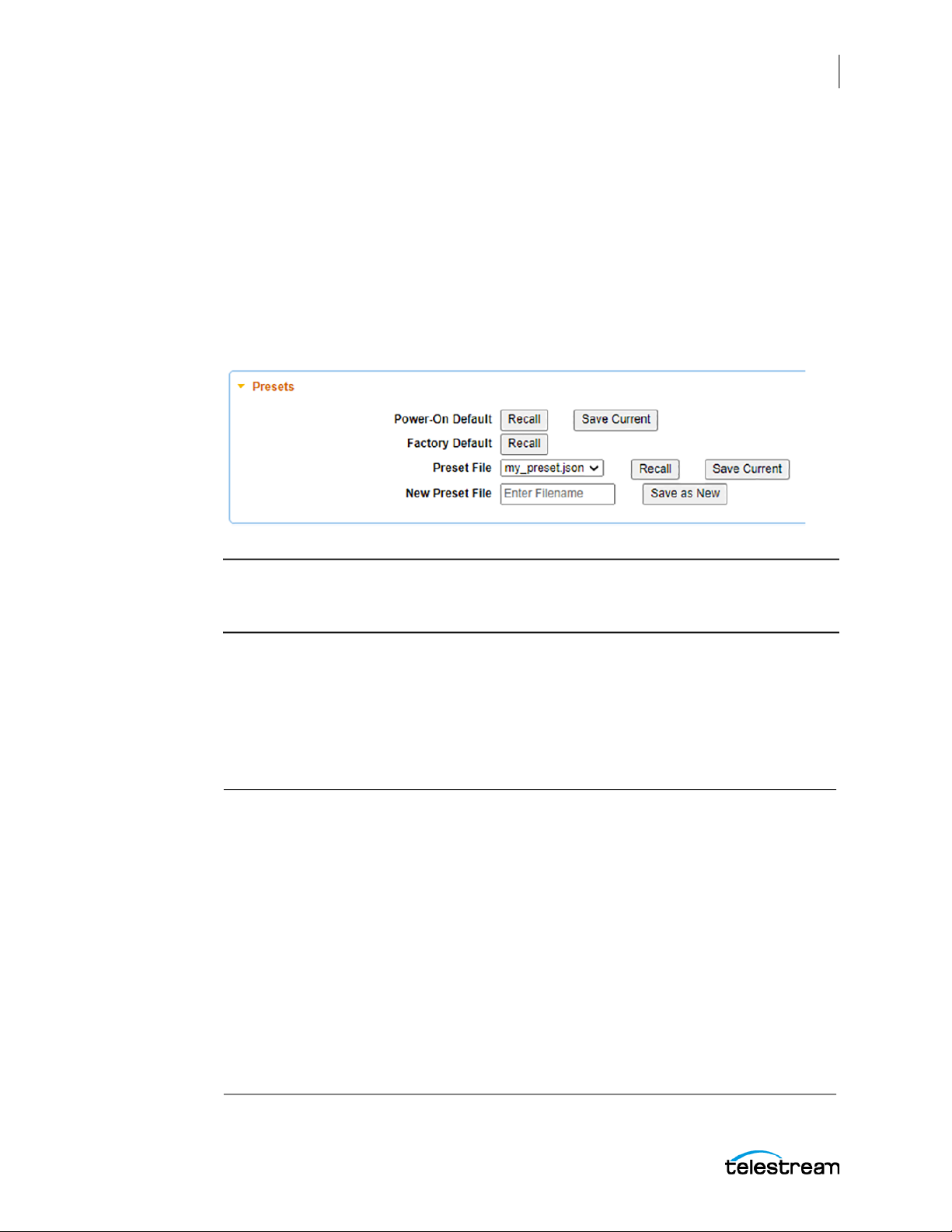
Presets
A preset is a set of configuration parameters for the instrument. Save and recall presets
to quickly change configuration settings at once, instead of changing each parameter
individually. The system maintains two special presets (power-on default and factory
default) and any number of user-defined presets:
Web Interface for Presets
In the SPG9000 web interface, select the System tab and then select Preset.
System Operation
Presets
69
Note: With the front panel interface, a user can save or recall the power-on default
preset, or recall the factory default preset. File operations are only supported on the
web interface.
Front Panel Menu for PRESET
To use the front panel of the SPG9000 for this process, press SYSTEM and then select
the PRESET option. See Menu Operations for details of using the front panel menus. The
table shows the submenus for the PRESET selection.
SYSTEM :
PRESET :
POWER-ON DEFAULT (to Save)
POWER-ON DEFAULT (to Recall)
FACTORY DEFAULT
INFO :
NETWORK :
FRONT PANEL :
WEB :
POWER SUPPLY :
FIRMWARE UPGRADE
CALIBRATE OVEN
DIAGNOSTICS
SPG9000 User Manual
Page 70

70
System Operation
Presets
Configuration Settings for Presets
Power-On Default
This preset is applied whenever the instrument is powered on. Save the current settings
to the Power-On Default preset so they are automatically restored when the instrument
is restarted. Recall this preset to reset the configuration since the last time the system
was restarted or since this preset was updated. This is useful for applications when the
SPG9000 is frequently powered off and on again, such as between different locations
for a mobile broadcast truck.
Factory Default
This preset includes the fixed factory default values for most configurable settings in
the instrument. Recall this preset to restore the instrument to a known state. The
Factory Default preset cannot be updated.
Preset File
There are several options for existing preset files:
Recall User-defined Preset
After the JSON file has been saved, it can be recalled at any time.
1. Select the preset file from the Preset File menu.
2. Select Recall to restore the configuration parameters from the preset file.
Update User-defined Preset
You can update an existing user-defined preset file.
1. Select the preset file from the Preset File menu.
2. Select Save Current to overwrite the preset file with the current configuration
parameters for the instrument.
New Preset File
User-defined presets are saved as JSON text files in non-volatile memory on the
instrument. To create a new user defined preset:
1. Enter the preset name in the New Preset File field.
2. Select Save as New.
3. The .json filename suffix is added automatically. The new file is added to the menu
for the Preset File actions.
SPG9000 User Manual
Page 71

Configuration Settings Not Saved in Presets
Several parameters are saved in non-volatile memory of the SPG9000 so they are
restored when the instrument is powered off and on again, but they are not saved in
preset files. These are parameters that typically would not change in different
operational environments, such as between different mobile production locations:
● Installed license keys
● Network parameters:
○ Hostname and domain name
○ Management port IP address, subnet mask and gateway address
○ PTP and IP port addresses, subnet masks, and gateway addresses
● Web server configuration:
○ Web interface passwords
○ API key
○ SSL certificates
System Operation
Presets
71
● Syslog configuration:
○ Server address
○ Transport protocol
○ Severity level
● Front panel interface settings:
○ Timeout duration
○ Display backlight brightness
○ Beeper enable
SPG9000 User Manual
Page 72

72
System Status and Monitoring
System Status and
Monitoring
The SPG9000 has multiple features for monitoring the status of the instrument and its
reference signals. The front panel has colored LED indicators for quickly checking
several status items, and a set of menus accessed from the STATUS button for more
detailed information. The web interface also shows the same indicators on the banner
at the top of the page and has a Status tab to see detailed information. The API has
several messages for getting the status of the reference, GNSS, and PTP functions.
SPG9000 User Manual
Page 73
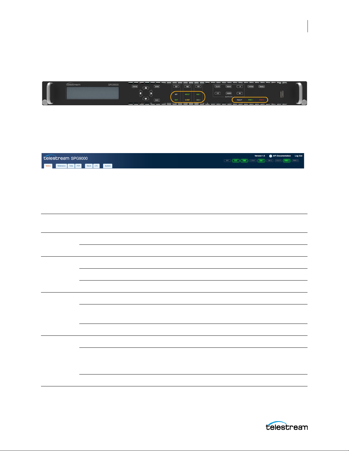
Indicators
There are nine colored LED indicators on the front panel of the instrument:
These indicators are mirrored on the web interface, on the right side of the banner at
the top of the page. When a physical front panel indicator changes state, the web page
indicator also changes.
The front panel indicators are grouped according to function:
Reference
System Status and Monitoring
Indicators
73
The INT and EXT indicators (located under the REF button) show the status of the
reference source. See Reference Sources.
Reference
Source
Internal Off Solid green Good
Genlock
Input
GNSS
1
Signal
PTP
Follower
EXT LED
State INT LED State Operational Status
Off Blinking green Warming up
Solid green Off Locked
Solid yellow Off Near Loss of Lock
Solid red Solid green Unlocked
Solid green Off Locked
Solid yellow Off FOM is less than the GNSS signal warning threshold.
See Signal Warning Threshold.
Solid red Solid green Unlocked or Holdover
Solid green Off Locked
2
Solid yellow Off The reference is locked to the PTP time, but the time
from the grandmaster is near the lock range limit of
the system.
Solid red Solid green Unlocked or Holdover
1. Option SPG9000-GNSS must be licensed to select GNSS Signal as the reference source.
2. Option SPG9000-PTP must be licensed to select PTP Follower as the reference source.
SPG9000 User Manual
Page 74

74
System Status and Monitoring
Indicators
Time
The INPUT indicator (located under the TIME button) shows the status of the main timeof-day (MTOD) source. On the web interface, the INPUT indicator is labeled TIME. See
Time-of-Day Sources for information on the MTOD source.
Time of Day
Source
(TIME) INPUT
LED State Operational Status
Internal Off Time is based on the internal main time-of-day register. This might
have been previously set by an external source or by manual input.
VITC Input Solid green VITC data is present in the genlock input signal and is being used
for the MTOD source.
Solid red There is no genlock input signal, or the signal is present and there is
no VITC data detected, or the VITC data is discontinuous.
LTC Input Solid green The LTC input signal is present and is being used for the MTOD
source.
Solid yellow The timing of the LTC input signal and the genlock input signal are
the same frame rate, but the relative timing is outside the SMPTE
ST 12 specification.
Solid red The LTC input signal is missing, the LTC data is discontinuous, or the
LTC frame rate is badly timed relative to the genlock input signal.
1
GNSS Signal
Solid green The system is using the time from the GNSS receiver as the MTOD
source.
Solid red The system is not locked to the GNSS signal.
2
PTP Follower
Solid green The system is using PTP time as the MTOD source.
Solid red The system is not locked to a PTP leader.
1. Option SPG9000-GNSS must be licensed to select GNSS Signal as the time and reference source
2. Option SPG9000-PTP must be licensed to select PTP Follower as the time and reference source
The X-REF indicator (also located under the TIME button) is for future use.
SPG9000 User Manual
Page 75

PTP
FAULT
System Status and Monitoring
Indicators
The GM 1 and GM 2 indicators (located under the PTP button) show the grandmaster
status of the PTP 1 and PTP 2 instances respectively. See PTP Configuration to configure
the PTP instances. Option SPG9000-PTP must be licensed to enable PTP operation.
GM LED State PTP Status
Bright green Active Leader
Dim green Passive Leader
Red Faulty
Off Listening, Disabled, or Follower
The FAULT indicator is illuminated when there is a problem with the instrument
hardware.
75
FAULT LED
State Instrument Condition Examples
Off The instrument is operating properly.
Solid yellow A fault condition exists, but the
instrument is still usable.
Blinking red A fault condition exists that has the
potential to damage the instrument
hardware.
Solid red A fault condition exists that renders
the instrument unusable.
See System Status to view the detailed diagnostic data. If the FAULT indicator is blinking
red or solid red, record the fault details, unplug the instrument from the power source,
and contact Telestream customer support.
• The phase-locked loops (PLLs) are unlocked.
• A power supply module has reached the
TWH limit. See Temperature-Weighted Hours.
• The main fans have stopped.
• The internal temperature is too high.
• A fan speed is out of range.
• An internal voltage is out of range.
SPG9000 User Manual
Page 76

76
System Status and Monitoring
Indicators
PWR 1 and PWR 2
These two indicators show the status of the two power supply modules.
Note: If the SPG9000 was purchased with option SPG9000-SPW, only one power
supply module is installed in the instrument. If it was purchased with option SPG9000DPW, two power supply modules are installed in the instrument. A second or
replacement power supply can be added at any time by purchasing option SPG9000ACC-DPW.
When one power supply module is installed, the corresponding PWR 1 or PWR 2
indicator is on and the other indicator is off.
PWR1 / PWR2
Indicator State
Green No faults Normal operation None
Yellow Warning
Power Supply
Module Condition Description User Actions
● A marginally out-of-
range power supply voltage is detected.
1. Install a second power
2. Remove the faulted power
● The supply has exceeded
the specified TWH. See
Temperature-Weighted
Hours.
● The power supply fan has
stopped.
Red Fault The power supply voltage is
out of range.
When two power supplies are installed, both PWR 1 and PWR 2 indicators are on.
PWR1 / PWR2
Indicator State
Off Not installed The power supply is not properly
Bright green No faults This is normal operation for the
Dim green No faults This is normal operation for the
Power Supply
Module Condition Description User Actions
installed; the system is only
detecting one power supply.
active power supply.
inactive (backup) power supply.
1. Install a second power
2. Remove the faulted power
supply module.
supply module for repair.
supply module.
supply module for repair.
Check that the module is
fully inserted into its rear
panel slot.
None
None
SPG9000 User Manual
Page 77

System Status and Monitoring
Indicators
77
PWR1 / PWR2
Indicator State
Yellow Warning or fault in
Red Fault or no power
Power Supply
Module Condition Description User Actions
the active supply
● A marginally out-of-range
power supply voltage for the
active supply is detected.
● The supply has exceeded the
specified TWH. See Tempera-
ture-Weighted Hours.
● The active supply fan has
stopped.
● The power cable for the sup-
ply is unplugged, or there is
no power from the source.
● The power supply voltage of
the active supply is out of
range.
● The fan of the backup supply
has stopped.
Note: In the case of a failed fan
on both supplies, the instrument
operates as long as the voltage is
adequate.
If the status of the
inactive supply is not
faulted (dim green),
remove the faulted
power supply module for
repair. The other supply
becomes active.
If the status of the
inactive supply is also
faulted (red), remove that
power supply module for
repair first.
● Verify the power
cable is connected to
the power supply
module and the
power cable is connected to the power
source.
● Remove the
associated power
supply module for
repair.
SPG9000 User Manual
Page 78
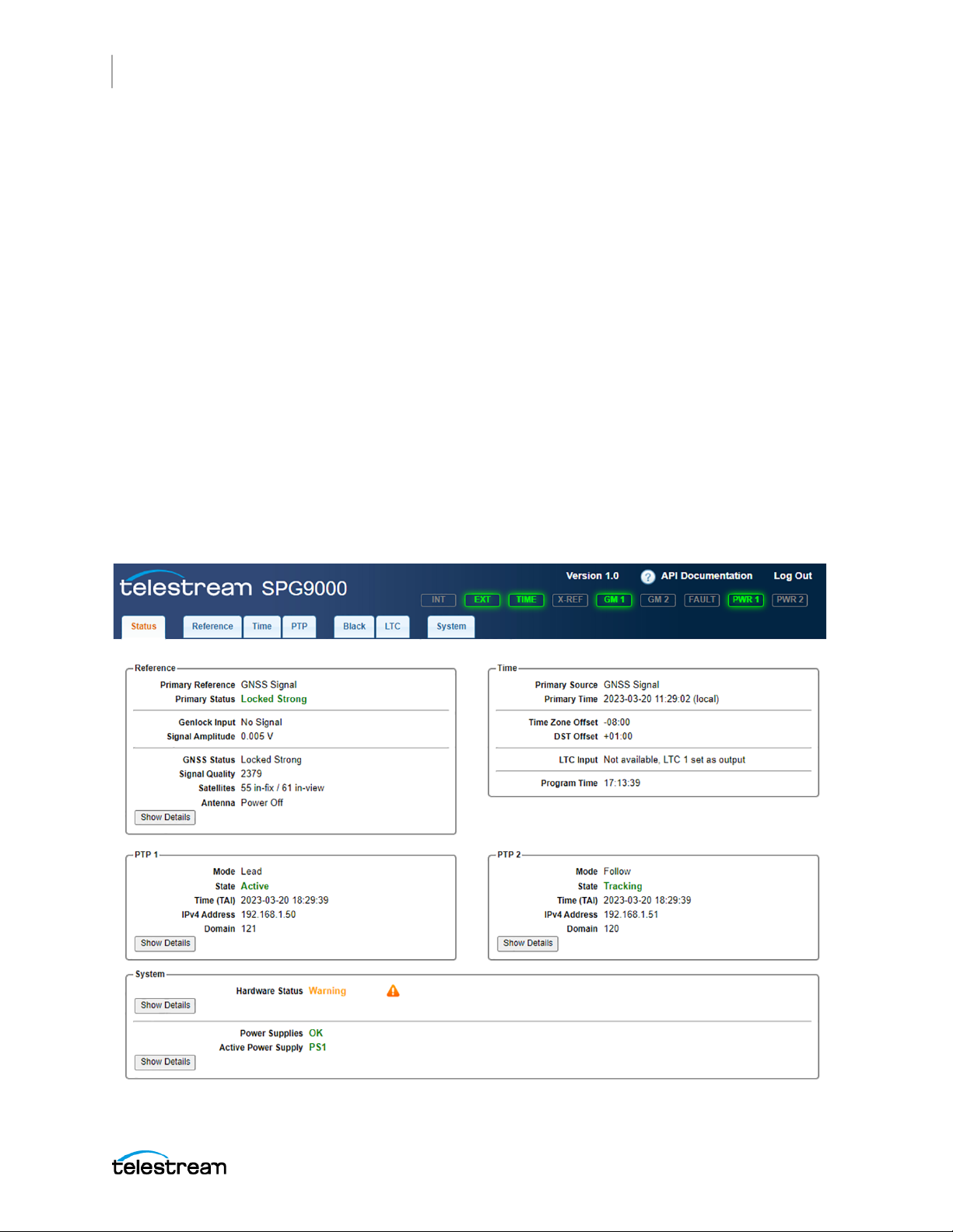
78
System Status and Monitoring
Status Information
Status Information
Detailed status information can be viewed on the Status tab of the web interface. The
displays are updated in real-time, so the user can see changes as they occur. A subset of
important status information can also be viewed from the front panel STATUS menu.
Web Interface for Status
On the SPG9000 web interface, click the Status tab.
The web page Status contents are organized into several main sections:
Reference includes information about the status of the primary reference source,
the genlock input signal, and the GNSS receiver status.
Time includes the current time-of-day from its primary source, any local time
offsets, status of any time code input, and the current value of the program time
counter.
PTP 1 and PTP 2 include status for the two PTP instances.
System includes diagnostic information for the system hardware, including the
power supply modules.
SPG9000 User Manual
Page 79
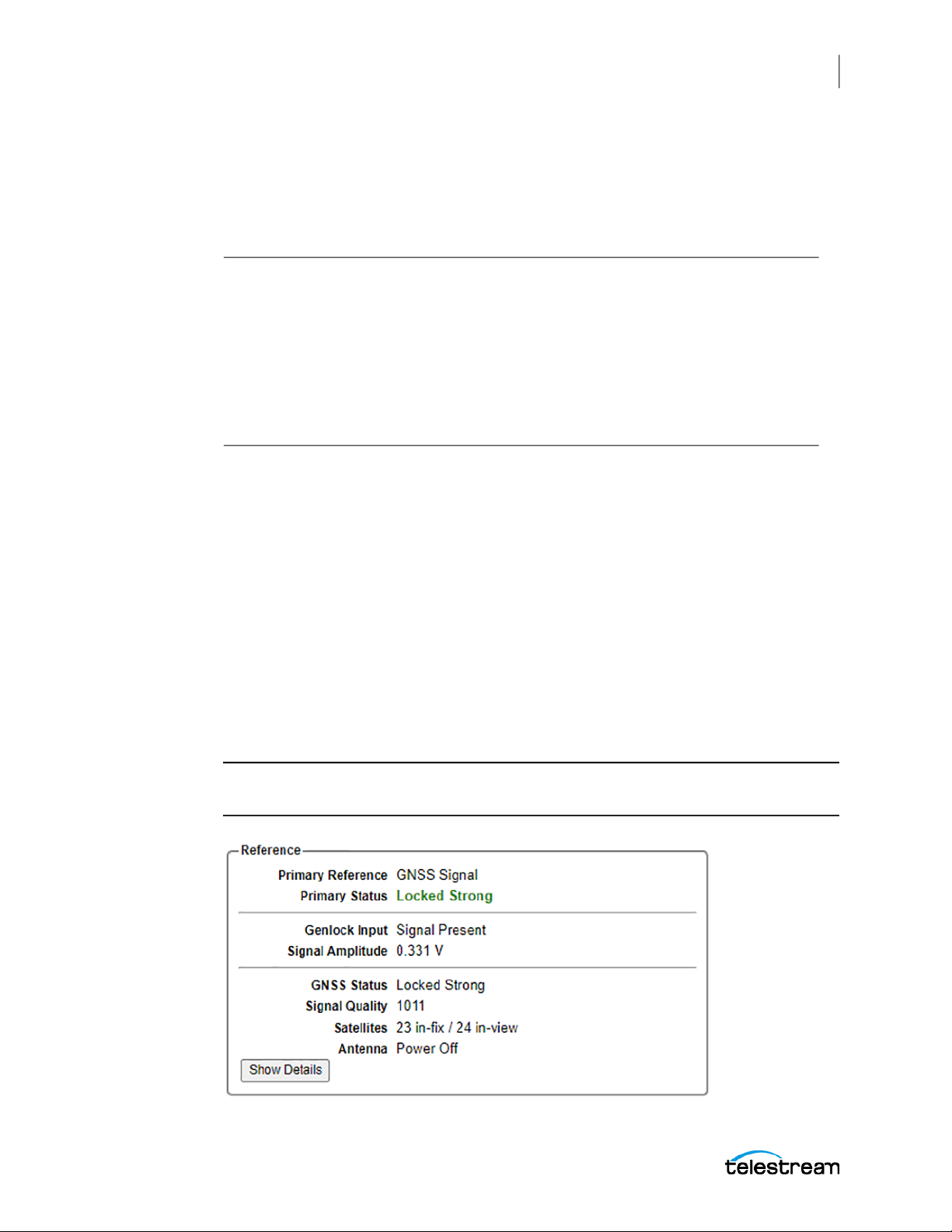
Front Panel Menu for STATUS
To use the front panel of the SPG9000 for this process, press STATUS. See Menu
Operations for details of using the front panel menus. The table shows the submenus
for the STATUS menu.
STATUS :
FAULT Only available if a fault is detected
ALERT Only available if there is an alert
REFERENCE
TIME :
PTP 1 : Only available if the SPG9000-PTP license is installed
PTP 2 : Only available if the SPG9000-PTP license is installed
GNSS : Only available if the SPG9000-GNSS license is installed
The front-panel menus for STATUS are multiple-page menus (see Multiple-Page Menus),
so the user can press the left and right arrow buttons to see all the available
information for the current menu.
System Status and Monitoring
Status Information
79
The FAULT submenu is only displayed if there are any hardware faults. This menu
provides additional details if the FAULT indicator is illuminated. See FAULT.
The ALERT submenu is only displayed if there are any signal warnings, such as a loss of
lock on the primary reference source. This menu is persistent, so if the alert condition is
cleared, the menu still shows the past status so the user can see the event happened.
Reference Status
The Reference section on the Status tab contains information about the current
reference source, the genlock input signal, and the received GNSS signal.
Note: Option SPG9000-GNSS must be licensed to view GNSS signal status. Without
the option, these items are not shown on the web page.
SPG9000 User Manual
Page 80

80
System Status and Monitoring
Status Information
Primary Reference
Displays the current reference source, one of:
● Internal
● Genlock Input
● GNSS Signal
● PTP Follower
Primary Status
Displays the status of the current reference source. The status text is colored green,
yellow, or red indicating good, warning, or error status respectively.
Reference
Source
Internal Off Green The internal oven-controlled MEMS oscillator is used as the
Genlock
Input
GNSS
1
Signal
Status
Value
Locked Green Locked to the genlock input signal
Near Loss of
Lock
Unlocked Red The system is unable to lock to the genlock input signal.
Unlocked Waiting for
Manual Lock
No Signal Red There is no detectable signal at the genlock input.
Locked
Strong
Locked
Nominal
Locked
Minimum
Status
Color Description
frequency reference.
Yellow The system is locked but within 1 × 10
tune range.
Red The system is waiting for user input to manually relock. This
happens when the Lock Action Mode is set to Manual. See Lock
Action Mode.
Green Locked to the GNSS signal with 8 or more satellites reporting a
carrier-to-noise ratio (C/N) of 40 dB or better
Green Locked to the GNSS signal with 4 or more satellites reporting
C/N of 30 dB or better
Green Locked to the GNSS signal with 4 or more satellites reporting
C/N of 10 dB or better
−6
of the limits of the
Locked
(possible
jamming or
spoofing)
Holdover Yellow The system has previously locked to the GNSS signal but is now
Yellow Locked to the GNSS signal but the receiver is reporting possible
jamming or spoofing of the received signal.
unlocked. The holdover mode continues until the system
relocks.
SPG9000 User Manual
Page 81

System Status and Monitoring
Status Information
81
Reference
Source
GNSS
Signal
(cont.)
PTP
Follower
2
Status
Value
Adjusting
Phase
Status
Color Description
Yellow The system has a good GNSS signal and is now adjusting its
time base and frame timing to align with the GNSS signal
within 150 ns.
Acquiring
Position
Yellow The system is acquiring multiple satellite fixes to compute a
new position that be stored in non-volatile memory.
Bad Position Yellow The system has detected that the stored position is different
from the current position. The position will be reacquired.
Acquiring
Satellites
Yellow The system is receiving satellite data to determine which
signals to use.
Unlocked Red The system is unable to lock to the GNSS signal because there is
no signal or the signal quality is too low.
Locked 50 ns Green The system is locked to the PTP leader with an
offsetFromMaster value of 50 ns or less, and the system phase is
within 50 ns of the PTP-derived timing.
Locked
100 ns
Green The system is locked to the PTP leader with an
offsetFromMaster value of 100 ns or less, and the system phase
is within 100 ns of the PTP-derived timing.
Locked
250 ns
Green The system is locked to the PTP leader with an
offsetFromMaster value of 250 ns or less, and the system phase
is within 250 ns of the PTP-derived timing.
Locked 1 µs Green The system is locked to the PTP leader with an
offsetFromMaster value of 1 µs or less, and the system phase is
within 500 ns of the PTP-derived timing.
Holdover Yellow The system has a valid PTP time from a previous lock, but the
PTP instance is no longer tracking the leader.
Adjusting
Phase
Yellow The PTP instance is tracking within 1 µs of the PTP leader and
the system is now adjusting its time base and frame timing to
align with the PTP-derived timing.
Listening Yellow The PTP instance is waiting to receive Announce and Sync
messages from a PTP leader in the same domain.
Unlocked Red The PTP instance is disabled, initializing, or faulty (possibly
because the link is down).
1. Option SPG9000-GNSS must be licensed to select GNSS Signal as the time and reference source
2. Option SPG9000-PTP must be licensed to select PTP Follower as the time and reference source
SPG9000 User Manual
Page 82

82
System Status and Monitoring
Status Information
Genlock Input
Displays information about the received genlock input signal (from the REF LOOP
connectors on the back panel). Detailed information is available when the reference
source is Genlock Input. Simple signal detection is the only available status when the
reference source is not Genlock Input.
Reference
source Genlock Input status Description
Genlock
Input
Internal or
GNSS Signal
or
PTP Follower
NTSC Burst The system is locked to the genlock input signal and the
input format is NTSC Burst.
PAL Burst The system is locked to the genlock input signal and the
input format is PAL Burst.
Any of the HD tri-level
formats, such as 1080
59.94i or 1080 25p
CW 10 MHz The system is locked to the genlock input signal and the
Signal Present There is a detectable signal on the genlock input, but the
No Signal There is no detectable signal on the genlock input.
Signal Present There is a detectable signal on the genlock input, but the
No Signal There is no detectable signal on the genlock input.
The system is locked to the genlock input signal and the
input format is HD Tri-Level. The specific tri-level sync format
is displayed. See Web Interface for Genlock Input.
input format is 10 MHz CW (continuous wave).
system cannot lock to it. This usually indicates a mismatch
between the expected genlock input format and the format
of the received signal.
system cannot identify the specific format when the
reference source is not Genlock Input.
Signal Amplitude
Displays the peak-to-peak signal level (in volts) measured at the genlock input. The
instrument can lock to signals within −8 to +6 dB of the nominal signal level for NTSC,
PAL, and HD tri-level formats and 0.5 to 2V for the CW 10 MHz signal.
If the displayed signal amplitude is greater than expected, the loop-through input on
the back panel might be unterminated. Connect the second connector to the genlock
reference input of another device or add a 75 Ω terminator.
GNSS Status
Displays the status of the received GNSS signal. The possible values and what they
mean are listed in the table.
SPG9000 User Manual
Page 83

System Status and Monitoring
Status Information
Note: Option SPG9000-GNSS must be licensed for the GNSS status items to appear on
the web interface.
GNSS Status Value Description
Locked Strong The GNSS signal has data from 8 or more satellites with a carrier-to-noise ratio
(C/N) of 40 dB or better.
Locked Nominal The GNSS signal has data from 4 or more satellites with C/N of 30 dB or better.
Locked Minimum The GNSS signal has data from 4 or more satellites with C/N of 10 dB or better.
83
Locked (possible
jamming or spoofing)
Acquiring Position The system is acquiring multiple satellite fixes to compute a new position
Unusable Signal The pulse-per-second (PPS) signal from the GNSS receiver is questionable.
Acquiring Satellites The system is receiving satellite data to determine which signals to use.
Low Signal Some satellites are in view, but none are in fix.
No Signal No satellites are in view. This is normal for a short time after the signal is
The GNSS receiver is reporting possible jamming or spoofing of the received
signal.
that will be stored in non-volatile memory.
applied but if this status persists it usually means one of three problems:
there is a problem in the antenna or cable; the antenna is blocked from direct
line of sight to the satellites; the power is not getting to the antenna.
Signal Quality
Displays the sum of C/N from all satellites currently in fix. A value of about 200 or higher
is usually sufficient for Locked Strong status.
Satellites
Displays the number of satellites in-fix and in-view. A satellite whose signal is received
by the internal GNSS receiver is counted in-view, but it must be used in the time and
position calculation to be counted in-fix. A satellite with a low C/N value, or that is low
in the sky (close to the horizon) is not used.
Antenna
Displays the status of the external GNSS antenna; the table explains what each value
means:
SPG9000 User Manual
Page 84
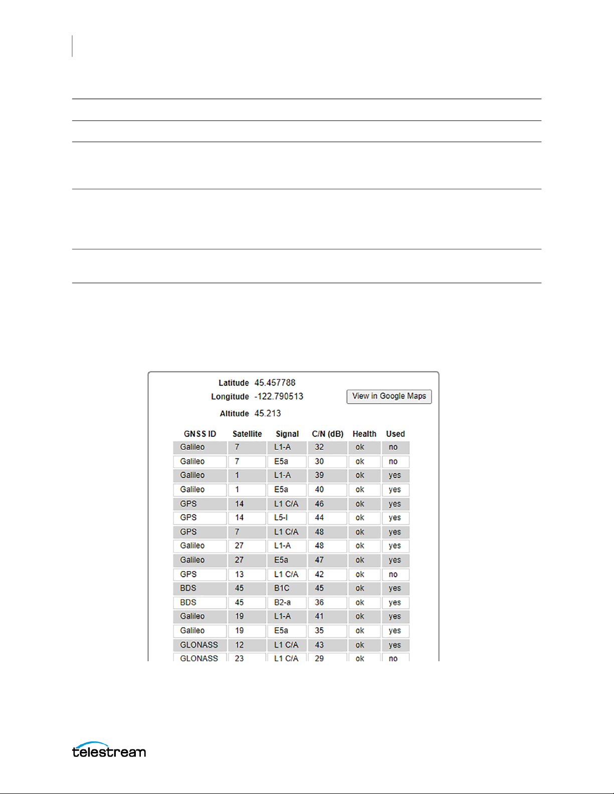
84
System Status and Monitoring
Status Information
Antenna status value Description
Normal Operation The external GNSS antenna is operating normally.
Power Off The antenna is not powered from the instrument. This is a normal condition if
the antenna is powered from an external source. See GNSS Receiver Settings to
change the antenna power settings.
Short Circuit The antenna is shorted. A shorted antenna does not damage the internal
GNSS receiver. If a splitter is used on the antenna, it might appear as a short at
DC but still pass through the RF signal, which would allow the internal GNSS
system to function.
Open Circuit An open circuit condition occurs if no antenna is connected or if the current
load is less than expected because a splitter or DC block is being used.
Show Details
Click to open a panel on the web interface that provides details information about the
received GNSS data. The position data of the GNSS antenna is shown along with a table
with data of every satellite that is currently in view.
SPG9000 User Manual
Page 85

System Status and Monitoring
Status Information
Latitude and Longitude
Displays the position in degrees of the GNSS antenna, which might be located at a
distance from the GNSS receiver inside the SPG9000. The latitude value is a positive
number (0 to 90) for the northern hemisphere and a negative number (−90 to 0) for the
southern hemisphere. The longitude value is a positive number (0 to 180) for the
eastern hemisphere and a negative value (−180 to 0) for the western hemisphere.
Altitude
Displays the altitude of the GNSS antenna location in meters relative to sea level.
View in Google Maps
Click to open a new browser tab with the location of the GNSS antenna shown at https:/
/google.com/maps. This can be used as a diagnostic aid to confirm that the GNSS signal
is showing the correction position if there are concerns that the signal is being spoofed.
GNSS ID
Indicates the Global Navigation Satellite System for this satellite.
85
GNSS ID System Name Operator Coverage
GPS Global Positioning System United States Global
GLONASS Global Navigation Satellite
System
Galileo Galileo European Union Global
BDS BeiDou Navigation Satellite
System
QZSS Quasi-Zenith Satellite System Japan Regional (Asia-Oceania, centered
Russia Global
China Global
around 135° E longitude)
Satellite
Displays the space vehicle identifier for this satellite. Each GNSS constellation has its
own numbering system for its set of satellites.
Signal
Displays the signal identifier. The GNSS receiver of the SPG9000 can receive signals
from both the L1 and L5 bands, but this also requires an external antenna that also
SPG9000 User Manual
Page 86
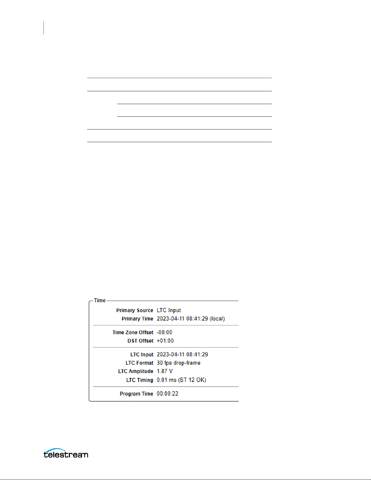
86
System Status and Monitoring
Status Information
supports L1 and L5 frequency bands. If the user only sees L1 signals in this table, it
usually means the antenna does not support L5 bands.
Bands Frequencies Constellations
L1 1575.42 MHz GPS, Galileo, QZS
L5 1176.45 MHz GPS, Galileo, BeiDou, QZSS
C/N (dB)
Displays the carrier-to-noise ratio in decibels of the satellite signal. Values above 10 are
usable for a nominal fix and values above 40 are used for a strong fix.
Health
Reports the satellite's health status. If the status is not ok, the satellite is reporting an
issue and the receiver would not use its data for a timing and position solution.
1561.098 MHz BeiDou
1602 MHz GLONASS
Used
Indicates if this satellite signal is used by the receiver for the timing and position
solution. Satellite data is usually used unless the vehicle is low in the sky (close to the
horizon) or its C/N value is low.
Time Status
The Time section on the Status tab contains information about the current time-of-day
source, local offsets, time code inputs, and the program time counter.
SPG9000 User Manual
Page 87

System Status and Monitoring
Status Information
Primary Source
Displays the current MTOD source, one of:
● Internal
● VITC Input
● LTC Input
● GNSS Signal
● PTP Follower
Primary Time
Displays the current main time-of-day value (date and time) including offsets for the
local time zone and daylight saving time if applicable.
Time Zone Offset
87
Displays the current time zone offset relative to UTC. For example, Central European
Time (CET) is shown as +01:00 and Pacific Time for North America is shown as -08:00.
DST Offset
Displays the current daylight saving time offset. For standard time, this is 00:00. For
daylight saving time (in regions that observe it), the offset is almost always 01:00.
VITC Status
Indicates the presence or absence of the Vertical Interval Time Code (VITC) data on the
genlock input signal. When VITC is present, its detected line number in the NTSC or PAL
input signal is displayed. The status shows "Discontinuous" for a few seconds if there is
an unexpected change in the received time code counter sequence.
VITC Input
Displays the received time code value. If the date and time zone information is encoded
(described in SMPTE ST 309), the displayed format is YYYY-MM-DD HH:MM:SS. If the
ST 309 data is missing, only the HH:MM:SS digits are displayed.
LTC Input
Displays the received Linear Time Code (LTC) value. LTC 1 must be set to Input mode for
the time code to be available. If the date and time zone information is encoded
SPG9000 User Manual
Page 88

88
System Status and Monitoring
Status Information
(described in ST 309), the displayed format is YYYY-MM-DD HH:MM:SS. If the ST 309
data is missing, only the HH:MM:SS digits are displayed.
Note: If the reference source is Genlock Input and the time-of-day source is either
VITC Input or Internal, the VITC status is displayed instead of the LTC status.
LTC Format
Displays the detected format of the LTC input signal, such as "30 fps drop-frame"
LTC Amplitude
Displays the detected signal level in volts of the LTC input signal
LTC Timing
Displays the timing offset in milliseconds between the LTC input signal and the genlock
input signal. The offset should be within −32 µs to +160 µs, according to SMPTE ST 12-1.
If the measured value is within these limits, a status of ST 12 OK is displayed. If the
measured value is outside these limits a status of ST 12 Warning is displayed.
Program Time
Displays the current value of the program time counter. See Program Time Counter.
PTP Status
The PTP 1 and PTP 2 sections on the Status tab contain information about the PTP
instances corresponding to the two networks ports labeled PTP 1 and PTP 2
respectively.
Note: Option SPG9000-PTP must be licensed for the PTP status items to appear on
the web interface.
SPG9000 User Manual
Page 89
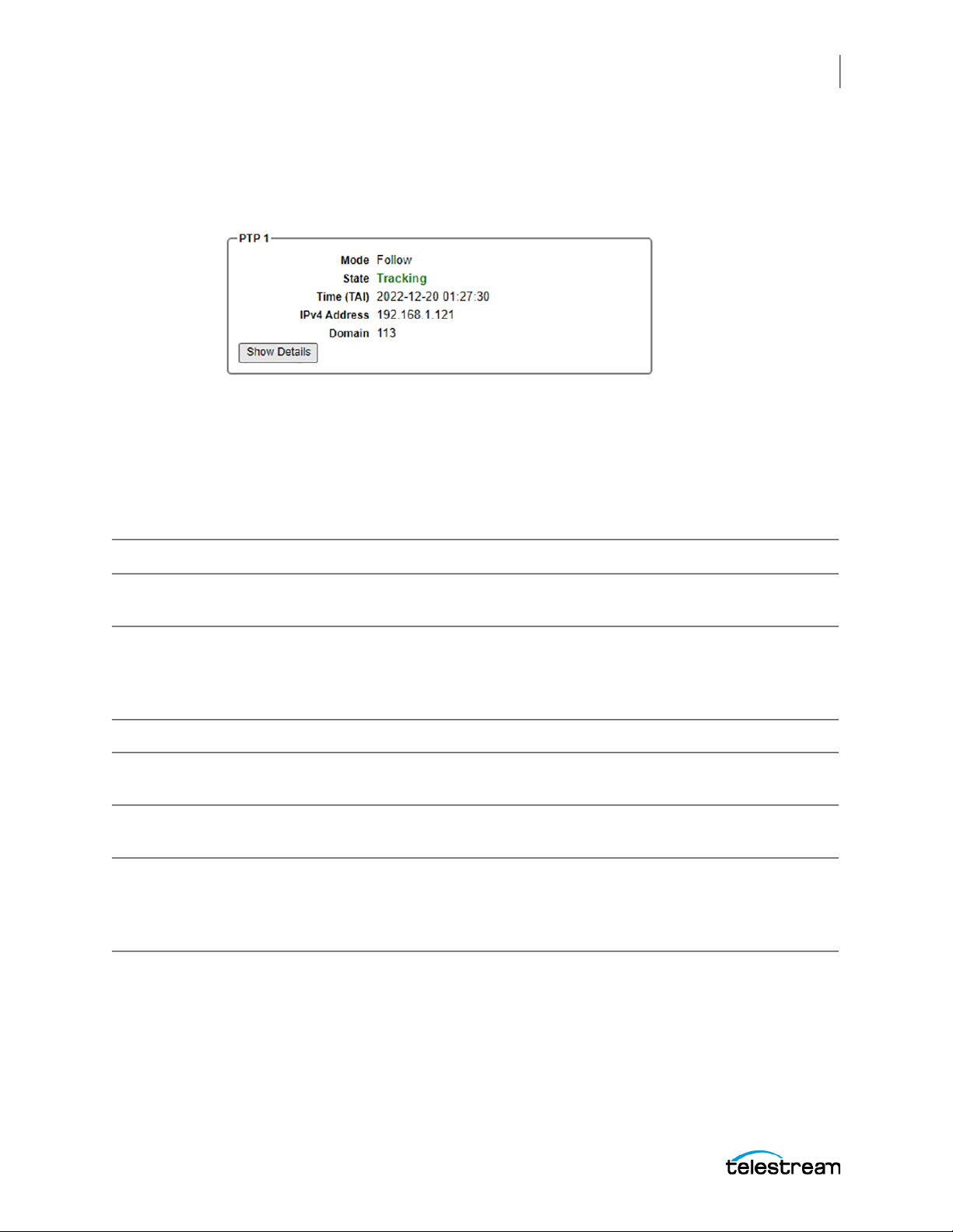
System Status and Monitoring
Status Information
Main PTP Status
The PTP status sections include some common items that are always visible as in the
example, and a details section that depends on the mode and state of the PTP instance.
Mode
Displays the mode of the PTP instance: Lead, Follow, or Ordinary Clock.
State
89
Displays the state of the PTP instance according to Table 27 of IEEE 1588-2019.
State Name IEEE 1588 State Description
Initializing INITIALIZING Temporary state when the PTP instance is re-started after some
configuration changes
Faulty FAULTY Fault state for the instance, usually because the Ethernet link is
down or the IP address is mis-configured. Check the rear panel port
indicators (see PTP 1-2 Ports) for link status. See Configuration
Settings for PTP Network Interfaces for the IP address settings.
Disabled DISABLED PTP instance is currently disabled.
Listening LISTENING PTP instance is waiting to receive Announce messages from any
PTP leaders on this domain.
Pre-master PRE_MASTER Temporary state before the instance becomes a lead clock for the
domain
Active or
Active Leader
MASTER Normal state for a leader that is the grandmaster (GM) for the
domain. The reference and time-of-day source of this instrument is
used for followers in this domain to lock to the GM. If the PTP Mode
is set to Ordinary Clock, the state name is shown as Active Leader.
Passive PASSIVE Normal state for a leader that is not the grandmaster for the
domain. Another PTP leader is functioning as the GM, but this
instance can assume the GM role if the Best Master Clock
Algorithm (BMCA) decides so. At that point, the instance
transitions from Passive to Active.
SPG9000 User Manual
Page 90

90
System Status and Monitoring
Status Information
State Name IEEE 1588 State Description
Uncalibrated UNCALIBRATED Temporary state while the PTP instance is making clock
adjustments so it can lock to the GM. The instance should
transition to the Tracking state when calibration is complete.
Tracking SLAVE Normal state for a follower that is locked to the GM for this domain
Time (TAI)
Displays the current time value that is being used by the PTP instance in its messages.
PTP uses International Atomic Time (TAI, Temps Atomique International), which is
different from Coordinated Universal Time (UTC) by exactly 37 seconds (as of 2023). TAI
is continuous and does not use leap seconds. See Leap Second Management.
The Primary Time value displayed at the top right of the Status tab is based on UTC,
with adjustments for time zone and DST offsets. Therefore, it differs from PTP TAI time
by at least 37 seconds. See Primary Time.
IPv4 Address
Displays the IP address for the PTP 1 or PTP 2 port. See Configuration Settings for PTP
Network Interfaces to configure the IP address parameters.
Domain
Displays the domain number for the PTP instance.
Details of Leader PTP Status
The PTP status sections display some information only when the PTP Mode is set to
Leader.
SPG9000 User Manual
Page 91
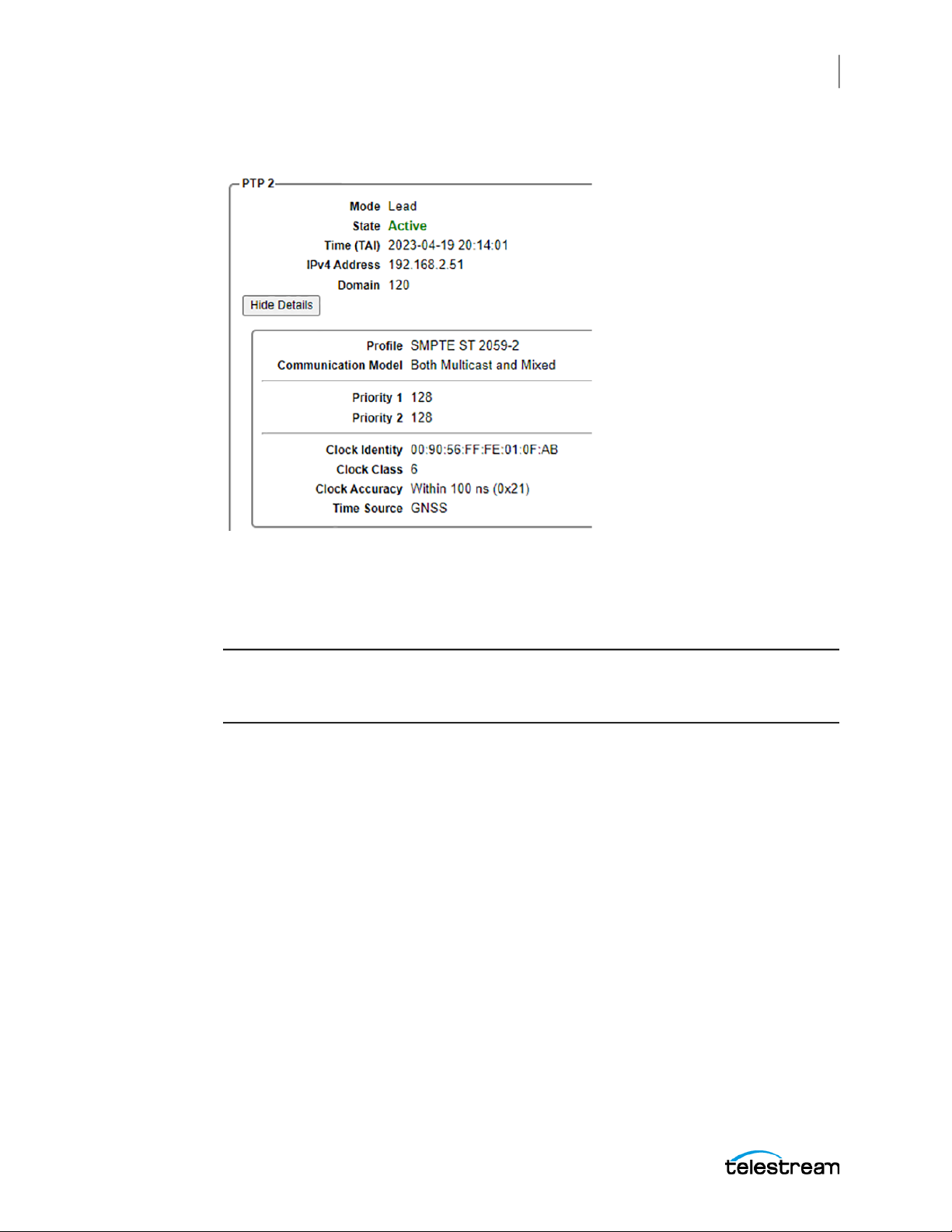
System Status and Monitoring
Status Information
Click Show Details to see the information. The button changes to Hide Details.
91
Profile
Displays the PTP profile in use for this instance:
● SMPTE ST 2059-2, typically used for video broadcast applications.
Note: Grandmasters send PTP Management messages once per second with a
Synchronization Metadata (SM) TLV. Followers using this profile decode the received
SM values.
● AES67, typically used for professional audio applications
● IEEE 1588-2019 Default
Communication Model
Displays the communication model in use by the profile:
● Both Multicast and Mixed: Leader can use either multicast or mixed models,
depending on the communication models used by its followers.
● Unicast: All PTP messages are sent to specific IPv4 destination addresses.
Priority 1 and Priority 2
Displays the priority 1 and priority 2 values used by this leader in Best Master Clock
Algorithm (BMCA) calculations. A lower number indicates a higher priority.
Clock Identity
Displays the clock identity of this leader instance. The clock identity is an 8-byte value
that is constructed from the first 3 bytes of the MAC address of the Ethernet port,
SPG9000 User Manual
Page 92

92
System Status and Monitoring
Status Information
followed by 0xFF FE, followed by the last 4 bytes of the MAC address. For example, a
MAC address of 00-90-56-01-10-01 (as viewed in the Network Settings section of the
System tab, see MAC Address) corresponds to a clock identity of 00:90:56:FF:FE:01:10:01.
Note: The first 3 bytes (00:90:56) of the clock identity values used by the SPG9000
correspond to the Organizationally Unique Identifier (OUI) of Telestream, LLC.
Clock Class
Displays the clock class attribute of this leader instance, according to Table 4 of IEEE
1588-2019. Some common values:
● 6: Instance is directly synchronized to a primary reference time source (such as
GNSS).
● 7: Instance was previously using clock class 6 but is now in holdover mode.
● 13: Reference source is Genlock Input and the time-of-day source is a time code
input (LTC or VITC) or internal time.
● 14: Instance was previously using clock class 13 but is now in Stay Genlock mode.
● 187: Instance is in Ordinary Clock mode and can be a follower in this domain.
● 248: Default value, used if the instrument is using an internal reference.
Clock Accuracy
Displays the clock accuracy attribute of this leader instance, according to table 5 of IEEE
1588-2019. Both the description and the numeric value (in hexadecimal) of the clock
accuracy are displayed.
Time Source
Displays the time source attribute of this leader instance, according to table 6 of IEEE
1588-2019. The SPG9000 can use any of these values:
● GNSS
● PTP
● Hand Set (Internal time-of-day)
● Serial Time Code (LTC or VITC)
Details of Follower PTP Status
The PTP status sections display some information only when the PTP Mode is set to
Follower.
SPG9000 User Manual
Page 93
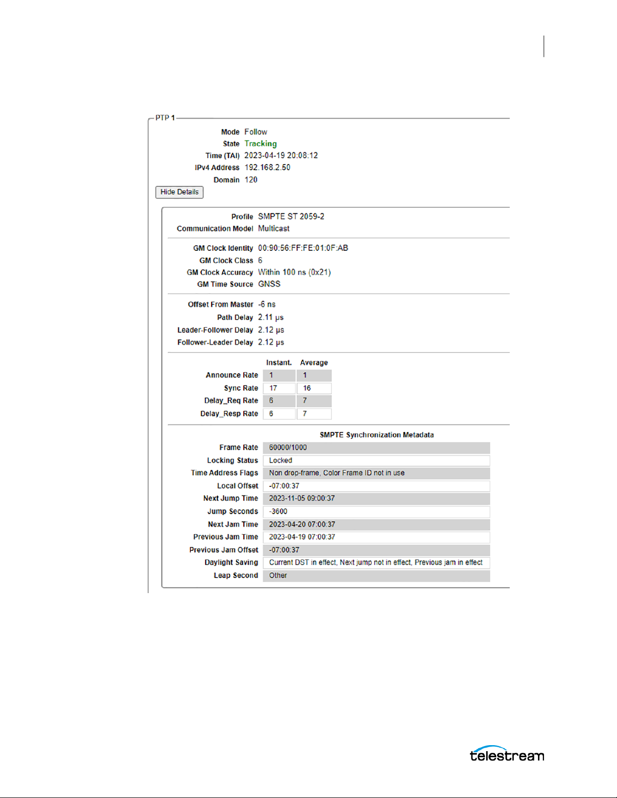
System Status and Monitoring
Status Information
Click Show Details to see the information. The button changes to Hide Details.
93
Profile
Displays the PTP profile in use for this instance: SMPTE ST 2059-2, AES67, or IEEE 15882019 Default
Communication Model
Displays the communication model in use by the profile:
SPG9000 User Manual
Page 94

94
System Status and Monitoring
Status Information
● Multicast: All PTP messages are sent using the assigned multicast IPv4 destination
address for PTP (224.0.1.129).
● Unicast: A ll PTP messages are sent to specific IPv4 destination addresses.
● Mixed Multicast/Unicast: Leaders use multicast for Announce, Sync, Follow_Up, and
Management messages. Followers use unicast for Delay_Req messages and the
leader also sends the Delay_Resp message as unicast.
GM Clock Identity
Displays the clock identity information that was sent in the Announce message from
the leader. See Clock Identity.
GM Clock Class
Displays the clock class information that was sent in the Announce message from the
leader. See Clock Class.
GM Clock Accuracy
Displays the clock accuracy information that was sent in the Announce message from
the leader. See Clock Accuracy.
GM Time Source
Displays the time source information that was sent in the Announce message from the
leader. See Time Source.
Offset From Master
Displays the current Offset From Master measurement, defined as the time error
between the lead clock and the follower clock as calculated from the PTP message
timestamps. This can be a positive or negative offset, ideally close to zero. A stable PTP
lock typically has an Offset From Master value of 100 nanoseconds or less.
Path Delay
Displays the current Path Delay measurement, defined as the mean of the LeaderFollower Delay and Follower-Leader Delay measurements. Typically, these delay values
are a few microseconds or less.
Leader-Follower Delay
Displays the current Leader-Follower Delay measurement, computed from the
timestamps used with Sync and Follow_Up messages. The leader-follower delay is
. See the messages example illustration.
t
2 − t1
SPG9000 User Manual
Page 95
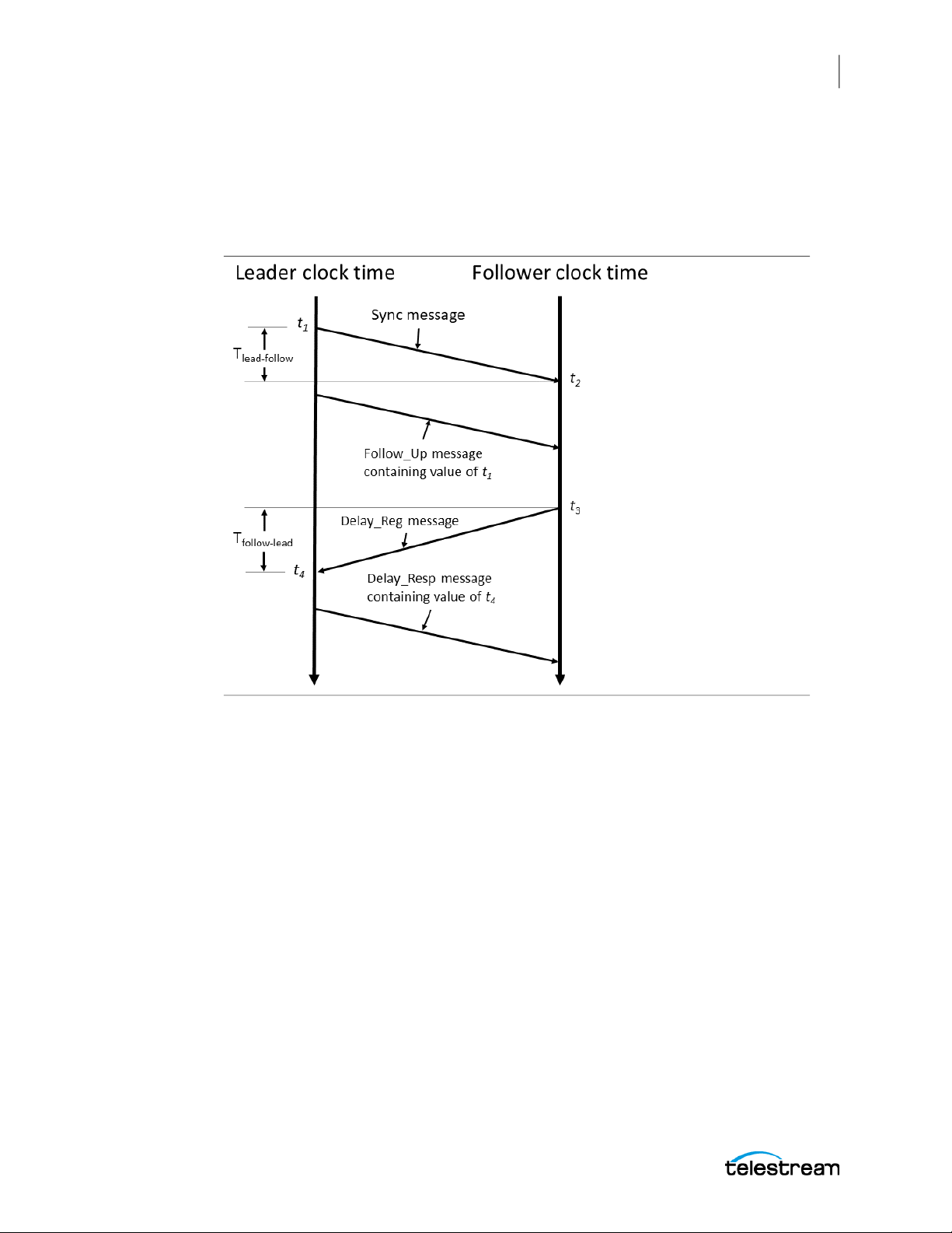
System Status and Monitoring
Status Information
Follower-Leader Delay
Displays the current Follower-Leader Delay measurement, computed from the
timestamps used with Delay_Req and Delay_Resp messages. The follower-leader delay
− t3. See the messages example illustration.
is t
4
95
Announce Rate
Displays the instantaneous and average message rates for Announce messages
received from all leaders. This rate can be used to verify that messages are being
received from at least one leader and at the expected rate.
Sync Rate
Displays the instantaneous and average message rates for Sync messages received
from all active leaders.
Delay_Req Rate
Displays the instantaneous and average message rates for Delay_Req messages
received from visible followers.
Delay_Resp Rate
Displays the instantaneous and average message rates for Delay_Resp messages
received from all leaders.
SPG9000 User Manual
Page 96
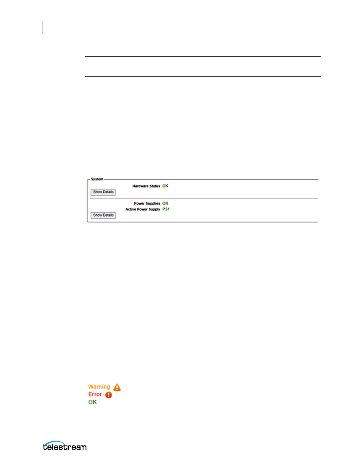
96
System Status and Monitoring
Status Information
Note: All messages received on the Ethernet port are counted, including those from
other domains.
SMPTE Synchronization Metadata
This table displays the values decoded from the most recent Management message
received with the SMPTE 2059-2 Synchronization Metadata (SM) TLV. The PTP profile
must be set to ST 2059-2 for this data to be sent from the leader and received by the
follower.
System Status
The System section at the bottom of the Status tab displays diagnostic information for
the instrument hardware.
Hardware Status
Indicates if the system is operating normally, or if there are any hardware faults or
warnings. Select Show Details to open a panel with detailed diagnostic information,
including:
● Power-On Self Test (POST) results
● Voltage measurements
● Fan speed measurements
● Temperature sensor measurements
● Oven-controlled MEMS oscillator diagnostic values
● Phase-locked loop (PLL) diagnostic values
● Real-time clock (RTC) battery status
● Other internal diagnostic values
If any values are displayed with a Warning or Error indicator, as in the example, the user
might need to contact Telestream Technical Support.
SPG9000 User Manual
Page 97

System Status and Monitoring
Status Information
Note: The error indicator is displayed when operating with two power supplies but
only one supply is connected to the power source. Connect the second supply to the
power source to clear the error condition. If the error indicator is still displayed after
the power source is connected to both supplies, replace the faulty supply.
Power Supplies
Shows the state of the power supply modules in the instrument. See Power Supply
Monitoring and Replacement for information on power supply operation.
Select Show Details to open a panel with power supply information:
● Which power supply is active
● Number of hours in which the power supply was active or on standby
● Load test history
97
SPG9000 User Manual
Page 98

98
Reference and Time Sources
Reference and Time
Sources
This section describes the frequency and time-of-day references for the SPG9000 and
how they are used to provide synchronization of its various outputs.
SPG9000 User Manual
Page 99
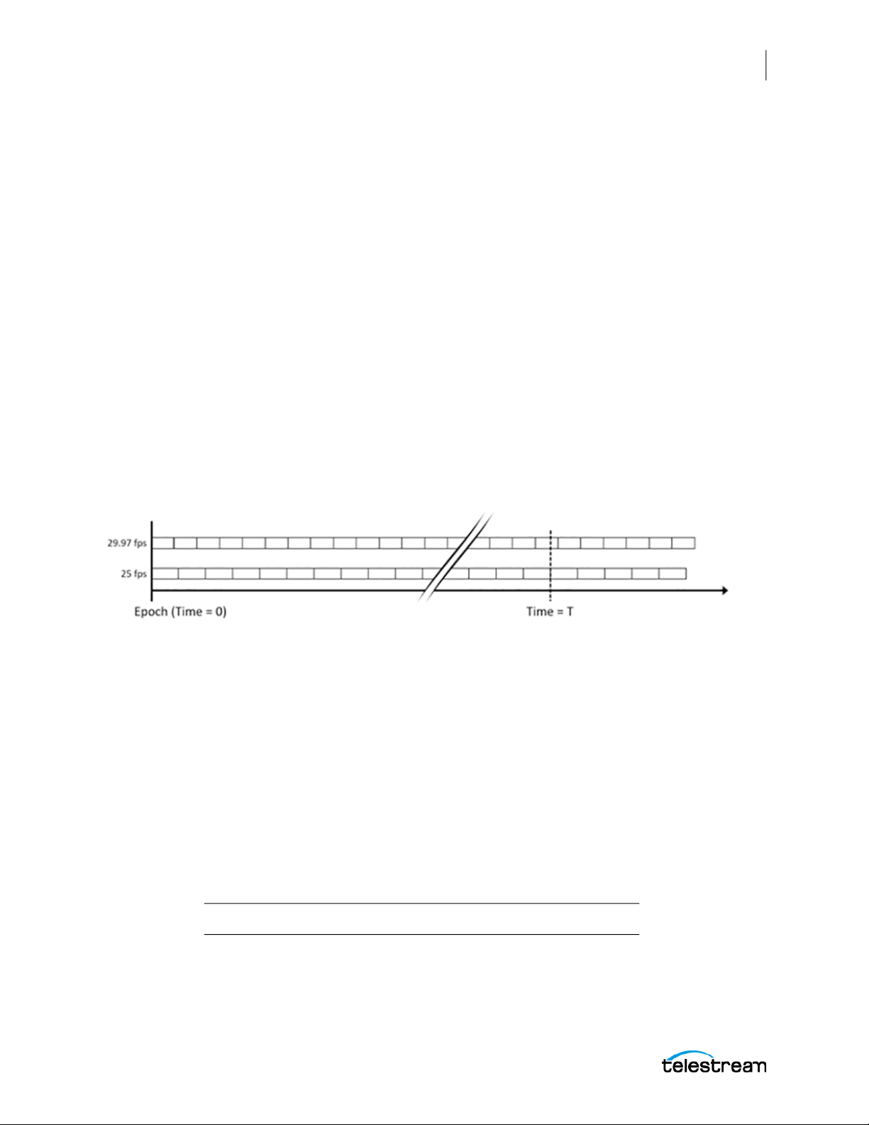
Theory of Operation
The SPG9000 functions by synchronizing its internal clock to a stable frequency source
and an accurate time-of-day source. Its outputs are in turn synchronized to that internal
clock, ensuring that all devices locked to the SPG9000 are all synchronized with each
other.
Epoch-Based Synchronization
The SPG9000 uses epoch-based synchronization. An epoch is a fixed moment in time
that is an absolute reference for subsequent events. The SMPTE epoch (defined in
ST 2059-1) and the PTP epoch (defined in IEEE 1588-2019) are both 00:00:00 on January
1, 1970 TAI (Temps Atomique International). At this time, we can consider video and
audio signals of various formats and frame rates to all be aligned with each other.
A video signal with a frame rate of 29.97 (30/1.001) frames per second has a frame
duration of about 33.367 ms, but video of 25 fps has a frame duration of 40 ms. At the
epoch, and exactly every 1001 seconds afterwards, the two frame sequences are
aligned. At any arbitrary time relative to the epoch, we can precisely compute the
expected phase of these (or any other) frame rates.
Reference and Time Sources
Theory of Operation
99
The SPG9000 uses a main time-of-day (MTOD) value that represents the integer and
fractional number of seconds since the epoch. For example, a time value of
1677608972.00000000 corresponds to February 28, 2023 at 18:29:32 TAI. TAI time does
not include leap seconds, and as of 2023, UTC time is behind TAI by exactly 37 seconds.
When the SPG9000 is synchronized to a GNSS signal it receives a pulse-per-second
(1 PPS) signal and a time-of-day value in a data message from its internal GNSS receiver.
When synchronized to another PTP grandmaster, it computes the time-of-day value
from the exchange of PTP messages. In either case, the SPG9000 adjusts its own MTOD
to align with the externally received time so the seconds of the MTOD increment at the
same time as the 1 PPS signal.
The SPG9000 also uses three frame-reset signals to synchronize its outputs (Black, LTC,
SDI) that can be set to different frame rates:
Frame Reset Clock Rate Video Format or Frame Rate (fps)
1 2.997 Hz NTSC, 29.97, 59.94, 23.98, 47.95
SPG9000 User Manual
Page 100
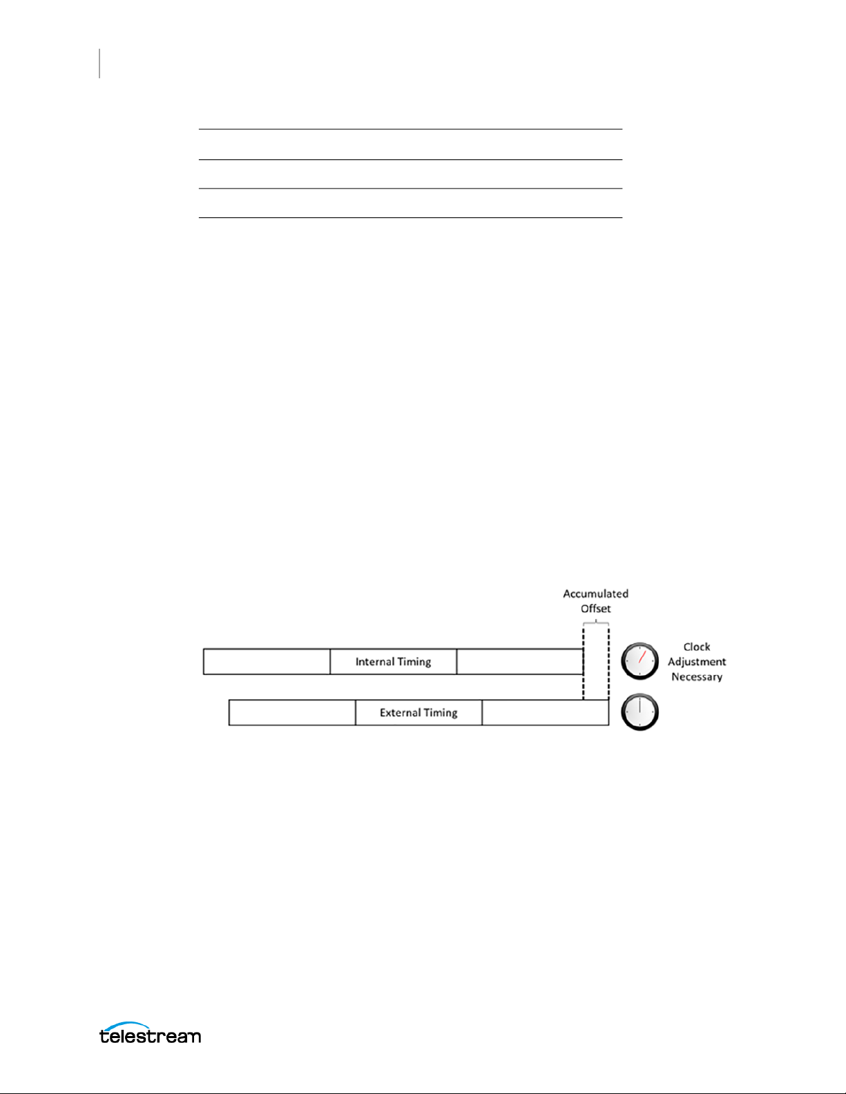
100
Reference and Time Sources
Theory of Operation
Frame Reset Clock Rate Video Format or Frame Rate (fps)
When locked to an absolute time source or when in internal mode, the three frames are
all aligned as if they started at the epoch. This enables the frames to have predictable
and consistent timing relationships and line up every 4004 seconds.
Phase Adjustment
When the SPG9000 is initially powered up and locks to the external reference, there is a
phase difference between the external and internal clocks. The SPG9000 forces the
internal clock to match the external reference for the initial lock and a quick startup.
When the instrument is locked to an external reference source, its internal clock is
continually and slowly adjusted to align with the external reference clock. These adjustments are small so the SPG9000 remains locked without any sudden synchronization or
abrupt phase changes.
2 6.250 Hz PAL, 25, 50
3 3.000 Hz 24, 30, 48, 60
Afterward, in normal operation, there could be a disruption to the external reference,
such as GNSS signal loss. In this case the SPG9000 goes into holdover mode and uses its
internal clock to maintain the timing based on the signal history just before signal loss.
If the instrument remains in holdover mode for an extended period, a timing offset
from the external reference accumulates.
When the external reference is restored, the SPG9000 finds the actual offset between its
internal clock to the reference source. The SPG9000 then goes into holdover recovery
mode to re-align the internal clock to the reference clock. The SPG9000 can slowly
make this adjustment within clock tolerances that are compliant with SMPTE standards
or the SPG9000 can force the adjustment for instant recovery. The stay legal mode
(adjustment-within-clock-tolerances method) can take a long time to recover (about
300 seconds for 64 µs line of timing error) but no synchronization shock occurs.
Reference Sources
There are four choices for the Reference source of the instrument.
SPG9000 User Manual
 Loading...