

Page 1

Lightspeed Live Guide
December 2016 208582
Capture 7.0.2
Stream 1.0.1
Page 2

2
Copyrights and Trademark Notices
Copyright © 2016 by Telestream, LLC. All rights reserved worldwide. No part of this
publication may be reproduced, transmitted, transcribed, altered, or translated into any
languages without the written permission of Telestream. Information and
specifications in this document are subject to change without notice and do not
represent a commitment on the part of Telestream.
Te le s t re a m. Telestream, CaptionMaker, Episode, Flip4Mac, FlipFactory, Flip Player,
Lightspeed, ScreenFlow, Switch, Vantage, Wirecast, Gameshow, GraphicsFactory,
MetaFlip, and Split-and-Stitch are registered trademarks and MacCaption, eCaptioning, Pipeline, Post Producer, Tempo, TrafficManager, and VOD Producer are
trademarks of Telestream, LLC. All other trademarks are the property of their respective
owners.
Adobe. Adobe® HTTP Dynamic Streaming Copyright © 2014 of Adobe Systems All right
reserved.
Apple. QuickTime, MacOS X, and Safari are trademarks of Apple, Inc. Bonjour, the
Bonjour logo, and the Bonjour symbol are trademarks of Apple, Inc.
Avid. Portions of this product Copyright 2012 Avid Technology, Inc.
Dolby. Dolby and the double-D symbol are registered trademarks of Dolby
Laboratories.
Fraunhofer IIS and Thomson Multimedia. MPEG Layer-3 audio coding technology
licensed from Fraunhofer IIS and Thomson Multimedia.
Google. VP6 and VP8 Copyright Google Inc. 2014 All rights Reserved.
MainConcept. MainConcept is a registered trademark of MainConcept LLC and
MainConcept AG. Copyright 2004 MainConcept Multimedia Technologies.
Manzanita. Manzanita is a registered trademark of Manzanita Systems, Inc.
MCW. HEVC Decoding software licensed from MCW.
MediaInfo. Copyright © 2002-2013 MediaArea.net SARL. All rights reserved.
THIS SOFTWARE IS PROVIDED BY THE COPYRIGHT HOLDERS AND CONTRIBUTORS “AS
IS” AND ANY EXPRESS OR IMPLIED WARRANTIES, INCLUDING, BUT NOT LIMITED TO, THE
IMPLIED WARRANTIES OF MERCHANTABILITY AND FITNESS FOR A PARTICULAR
PURPOSE ARE DISCLAIMED. IN NO EVENT SHALL THE COPYRIGHT HOLDER OR
CONTRIBUTORS BE LIABLE FOR ANY DIRECT, INDIRECT, INCIDENTAL, SPECIAL,
EXEMPLARY, OR CONSEQUENTIAL DAMAGES (INCLUDING, BUT NOT LIMITED TO,
PROCUREMENT OF SUBSTITUTE GOODS OR SERVICES; LOSS OF USE, DATA, OR PROFITS;
OR BUSINESS INTERRUPTION) HOWEVER CAUSED AND ON ANY THEORY OF LIABILITY,
WHETHER IN CONTRACT, STRICT LIABILITY, OR TORT (INCLUDING NEGLIGENCE OR
OTHERWISE) ARISING IN ANY WAY OUT OF THE USE OF THIS SOFTWARE, EVEN IF
ADVISED OF THE POSSIBILITY OF SUCH DAMAGE.
Microsoft. Microsoft, Windows NT|2000|XP|XP Professional|Server 2003|Server 2008
|Server 2012, Windows 7, Windows 8, Media Player, Media Encoder, .Net, Internet
Lightspeed Live Guide
Page 3

Explorer, SQL Server 2005|2008|Server 2012, and Windows Media Technologies are
trademarks of Microsoft Corporation.
SharpSSH2. SharpSSH2 Copyright (c) 2008, Ryan Faircloth. All rights reserved.
Redistribution and use in source and binary forms, with or without modification, are
permitted provided that the following conditions are met:
Redistributions of source code must retain the above copyright notice, this list of
conditions and the following disclaimer.
Redistributions in binary form must reproduce the above copyright notice, this list of
conditions and the following disclaimer in the documentation and/or other materials
provided with the distribution.
Neither the name of Diversified Sales and Service, Inc. nor the names of its contributors
may be used to endorse or promote products derived from this software without
specific prior written permission.
THIS SOFTWARE IS PROVIDED BY THE COPYRIGHT HOLDERS AND CONTRIBUTORS “AS
IS” AND ANY EXPRESS OR IMPLIED WARRANTIES, INCLUDING, BUT NOT LIMITED TO, THE
IMPLIED WARRANTIES OF MERCHANTABILITY AND FITNESS FOR A PARTICULAR
PURPOSE ARE DISCLAIMED. IN NO EVENT SHALL THE COPYRIGHT OWNER OR
CONTRIBUTORS BE LIABLE FOR ANY DIRECT, INDIRECT, INCIDENTAL, SPECIAL,
EXEMPLARY, OR CONSEQUENTIAL DAMAGES (INCLUDING, BUT NOT LIMITED TO,
PROCUREMENT OF SUBSTITUTE GOODS OR SERVICES; LOSS OF USE, DATA, OR PROFITS;
OR BUSINESS INTERRUPTION) HOWEVER CAUSED AND ON ANY THEORY OF LIABILITY,
WHETHER IN CONTRACT, STRICT LIABILITY, OR TORT (INCLUDING NEGLIGENCE OR
OTHERWISE) ARISING IN ANY WAY OUT OF THE USE OF THIS SOFTWARE, EVEN IF
ADVISED OF THE POSSIBILITY OF SUCH DAMAGE.
3
Te le r i k. RadControls for ASP.NET AJAX copyright Telerik All rights reserved.
Voi ce Age . This product is manufactured by Telestream under license from VoiceAge Corporation.
x264 LLC. The product is manufactured by Telestream under license from x264 LLC.
Xceed. The Software is Copyright ©1994-2012 Xceed Software Inc., all rights reserved.
ZLIB. Copyright (C) 1995-2013 Jean-loup Gailly and Mark Adler.
Other brands, product names, and company names are trademarks of their respective
holders, and are used for identification purpose only.
Lightspeed Live Guide
Page 4

4
MPEG Disclaimers
MPEGLA MPEG2 Patent
ANY USE OF THIS PRODUCT IN ANY MANNER OTHER THAN PERSONAL USE THAT
COMPLIES WITH THE MPEG-2 STANDARD FOR ENCODING VIDEO INFORMATION FOR
PACKAGED MEDIA IS EXPRESSLY PROHIBITED WITHOUT A LICENSE UNDER APPLICABLE
PATENTS IN THE MPEG-2 PATENT PORTFOLIO, WHICH LICENSE IS AVAILABLE FROM
MPEG LA, LLC, 4600 S. Ulster Street, Suite 400, Denver, Colorado 80237 U.S.A.
MPEGLA MPEG4 VISUAL
THIS PRODUCT IS LICENSED UNDER THE MPEG-4 VISUAL PATENT PORTFOLIO LICENSE
FOR THE PERSONAL AND NON-COMMERCIAL USE OF A CONSUMER FOR (i) ENCODING
VIDEO IN COMPLIANCE WITH THE MPEG-4 VISUAL STANDARD (“MPEG-4 VIDEO”) AND/
OR (ii) DECODING MPEG-4 VIDEO THAT WAS ENCODED BY A CONSUMER ENGAGED IN A
PERSONAL AND NON-COMMERCIAL ACTIVITY AND/OR WAS OBTAINED FROM A VIDEO
PROVIDER LICENSE IS GRANTED OR SHALL BE IMPLIED FOR ANY OTHER USE.
ADDITIONAL INFORMATION INCLUDING THAT RELATING TO PROMOTIONAL, INTERNAL
AND COMMERCIAL USES AND LICENSING MAY BE OBTAINED FROM MPEG LA, LLC. SEE
HTTP://WWW.MPEGLA.COM.
MPEGLA AVC
THIS PRODUCT IS LICENSED UNDER THE AVC PATENT PORTFOLIO LICENSE FOR THE
PERSONAL USE OF A CONSUMER OR OTHER USES IN WHICH IT DOES NOT RECEIVE
REMUNERATION TO (i) ENCODE VIDEO IN COMPLIANCE WITH THE AVC STANDARD
(“AVC VIDEO”) AND/OR (ii) DECODE AVC VIDEO THAT WAS ENCODED BY A CONSUMER
ENGAGED IN A PERSONAL ACTIVITY AND/OR WAS OBTAINED FROM A VIDEO PROVIDER
LICENSED TO PROVIDE AVC VIDEO. NO LICENSE IS GRANTED OR SHALL BE IMPLIED FOR
ANY OTHER USE. ADDITIONAL INFORMATION MAY BE OBTAINED FROM MPEG LA, L.L.C.
SEE HTTP://WWW.MPEGLA.COM.
MPEG4 SYSTEMS
THIS PRODUCT IS LICENSED UNDER THE MPEG-4 SYSTEMS PATENT PORTFOLIO LICENSE
FOR ENCODING IN COMPLIANCE WITH THE MPEG-4 SYSTEMS STANDARD, EXCEPT THAT
AN ADDITIONAL LICENSE AND PAYMENT OF ROYALTIES ARE NECESSARY FOR
ENCODING IN CONNECTION WITH (i) DATA STORED OR REPLICATED IN PHYSICAL MEDIA
WHICH IS PAID FOR ON A TITLE BY TITLE BASIS AND/OR (ii) DATA WHICH IS PAID FOR ON
A TITLE BY TITLE BASIS AND IS TRANSMITTED TO AN END USER FOR PERMANENT
STORAGE AND/OR USE. SUCH ADDITIONAL LICENSE MAY BE OBTAINED FROM MPEG LA,
LLC. SEE HTTP://WWW.MPEGLA.COM FOR ADDITIONAL DETAILS.
Lightspeed Live Guide
Page 5

Limited Warranty and Disclaimers
Telestream, LLC (the Company) warrants to the original registered end user that the
product will perform as stated below for a period of one (1) year from the date of
shipment from factory:
Hardware and Media—The Product hardware components, if any, including equipment
supplied but not manufactured by the Company but NOT including any third party
equipment that has been substituted by the Distributor for such equipment (the
“Hardware”), will be free from defects in materials and workmanship under normal
operating conditions and use.
Warranty Remedies
Your sole remedies under this limited warranty are as follows:
Hardware and Media—The Company will either repair or replace (at its option) any
defective Hardware component or part, or Software Media, with new or like new
Hardware components or Software Media. Components may not be necessarily the
same, but will be of equivalent operation and quality.
5
Software Updates
Except as may be provided in a separate agreement between Telestream and You, if
any, Telestream is under no obligation to maintain or support the Software and
Telestream has no obligation to furnish you with any further assistance, technical
support, documentation, software, update, upgrades, or information of any nature or
kind.
Restrictions and Conditions of Limited Warranty
This Limited Warranty will be void and of no force and effect if (i) Product Hardware or
Software Media, or any part thereof, is damaged due to abuse, misuse, alteration,
neglect, or shipping, or as a result of service or modification by a party other than the
Company, or (ii) Software is modified without the written consent of the Company.
Limitations of Warranties
THE EXPRESS WARRANTIES SET FORTH IN THIS AGREEMENT ARE IN LIEU OF ALL OTHER
WARRANTIES, EXPRESS OR IMPLIED, INCLUDING, WITHOUT LIMITATION, ANY
WARRANTIES OF MERCHANTABILITY OR FITNESS FOR A PARTICULAR PURPOSE. No oral
or written information or advice given by the Company, its distributors, dealers or
agents, shall increase the scope of this Limited Warranty or create any new warranties.
Geographical Limitation of Warranty—This limited warranty is valid only within the
country in which the Product is purchased/licensed.
Lightspeed Live Guide
Page 6

6
Damages
Limitations on Remedies—YOUR EXCLUSIVE REMEDIES, AND THE ENTIRE LIABILITY OF
TELESTREAM, LLC WITH RESPECT TO THE PRODUCT, SHALL BE AS STATED IN THIS
LIMITED WARRANTY. Your sole and exclusive remedy for any and all breaches of any
Limited Warranty by the Company shall be the recovery of reasonable damages which,
in the aggregate, shall not exceed the total amount of the combined license fee and
purchase price paid by you for the Product.
TELESTREAM, LLC SHALL NOT BE LIABLE TO YOU FOR ANY DAMAGES, INCLUDING ANY
LOST PROFITS, LOST SAVINGS, OR OTHER INCIDENTAL OR CONSEQUENTIAL DAMAGES
ARISING OUT OF YOUR USE OR INABILITY TO USE THE PRODUCT, OR THE BREACH OF
ANY EXPRESS OR IMPLIED WARRANTY, EVEN IF THE COMPANY HAS BEEN ADVISED OF
THE POSSIBILITY OF THOSE DAMAGES, OR ANY REMEDY PROVIDED FAILS OF ITS
ESSENTIAL PURPOSE.
Further information regarding this limited warranty may be obtained by writing:
Telestream
848 Gold Flat Road
Nevada City, CA 95959 USA
You can call Telestream via telephone at (530) 470-1300.
Regulatory Compliance
Electromagnetic Emissions: FCC Class A, EN 55022 Class A, EN 61000-3-2/-3-3, CISPR 22
Class A
Electromagnetic Immunity: EN 55024/CISPR 24, (EN 61000-4-2, EN 61000-4-3, EN
61000-4-4, EN 61000-4-5, EN 61000-4-6, EN 61000-4-8, EN 61000-4-11)
Safety: CSA/EN/IEC/UL 60950-1 Compliant, UL or CSA Listed (USA and Canada), CE
Marking (Europe)
California Best Management Practices Regulations for Perchlorate Materials:
This Perchlorate warning applies only to products containing CR (Manganese Dioxide)
Lithium coin cells. Perchlorate Material-special handling may apply. See
www.dtsc.ca.gov/hazardouswaste/perchlorate.
Guide Part number: 208582
Publication Date: December 2016
Lightspeed Live Guide
Page 7

Contents
Introduction 15
What the Lightspeed Live Server Includes 15
Overview 16
Lightspeed Live Stream 16
Lightspeed Live Capture 17
Using Live Stream and Live Capture Concurrently 17
Shared Resource Allocation 17
Certain Stream Sources are Not Supported for Capture Use 17
Lightspeed Live Server 18
System Power 19
Drives 19
Front Control Panel 19
Cooling System 19
SDI Input Cards 19
GPU 20
Expansion Input Card Slots 21
Front Panel 22
Front Panel Features 22
Rear Panel 23
Video Input Connections 24
7
Server Installation and Maintenance 25
Installing the Server 26
Unpacking 26
Rack Installation 27
Assembling the Rails 27
Installing Outer Rails into a Rack 28
Installing the Server in the Rack 29
Making Connections 30
Data and Signal Connections 30
Power Requirements and Connections 31
Power and General Cautions and Warnings 31
Operating System 33
Page 8

8
Contents
Microsoft Activation Key 33
Microsoft Updates 33
Windows User ID and Password 33
Windows Firewall 33
Maintaining the Server 34
Performance Tuning a Lightspeed Live Server 34
Backing up the Lightspeed Live Server 35
Managing the Lightspeed Live Server 36
Installing New or Replacement Hard Drives 37
Rebuilding the Lightspeed Live Storage RAID 38
Replacing Power Supplies 38
Replacing the Power Supply 38
Monitoring Lightspeed Live via SNMP 39
Configuring and Updating Live Capture 41
What Is Lightspeed Live Capture? 42
When is an Array License Needed? 43
Warning: Do Not Remove the Stream Application 43
Configuring Settings for Your Facility 44
Configuring Ingest Sources 48
Configuring a Channel Group Nexus 48
Configuring SDI Sources 50
When Live Stream and Capture are Used on the Same Server 50
Previewing Sources 51
Changing the Source Name 51
Configuring SDI Source Options 51
Creating a Live Capture Workflow 55
Creating a VTR Capture Workflow 59
Troubleshooting the VTR Connection 61
Live Capture Server Configuration Changes 62
Renaming a Lightspeed Live Capture Server 62
Joining Multiple Capture Servers 64
Capture-Only Systems 64
Existing Vantage Array - Adding Live Capture Server(s) 65
Uniquely Named Multiple Capture Servers 66
Best Practice for Multiple Live Capture Server System Design 67
Connecting the Applications for Multiple Servers 69
Configuring Vantage Client Applications for Multiple Servers 69
Using the Live Capture Web App with Multiple Servers 70
Updating Your Server using Secured Version Control and ComponentPacs 71
Installing a ComponentPac Update 72
Updating Workflows and Actions for ComponentPacs 73
Clear Browsing Data after Updating Vantage or Live Capture 74
The Lightspeed Live Capture Web Application 75
Lightspeed Live Capture Web App Overview 76
Lightspeed Live Guide
Page 9

Installing the Lightspeed Live Capture Web App 77
Installation on Standard Servers 77
Clear Browsing Data after Updating 77
Accessing the Lightspeed Live Capture Web App 78
Changing the Domain 78
Launching the Web Applications Menu 79
Opening the Live Capture Application 79
Selecting a Channel Group 80
Channel Group List 80
Creating a New Channel Group 80
Using the Lightspeed Live Capture Web App 81
Set Capture Action to Manual or VTR for Channel Control 81
Channel View Panel 81
Basic Information and Control Display 82
Lightspeed Live Capture Menu Panel 82
Channel Groups 82
Master Channel Actions 82
Configuration 83
Help 83
Manual Mode Controls and Indicators 84
Controls for Manual Mode 84
Indicators and Information in the Channel Control Dialog 88
VTR Mode Controls and Indicators 90
RS-422 Interface Device 90
Controls for VTR Mode 91
Schedule and Web Service Controls and Indicators 93
When a Single Event is Queued for Capture 93
When Multiple Events are Queued for Capture 94
Recorded File Location and Format 95
Using the Job Status Views 96
Opening Job Status Views 96
The Job Status Views Web Application 97
Contents
9
Creating Capture Workflows 99
Lightspeed Live Capture Resource Calculator 100
Configuring and Updating Live Stream 105
Updating the Lightspeed Live Stream Software 106
Renaming a Lightspeed Live Stream Server 106
Lightspeed Live Guide
Determining the Time-Shift Buffer Duration 101
Standard Definition (SD) Codecs 101
High Definition (HD) Codecs 101
UHD/4K Codecs 101
Calculating your Resource Usage Capacity 101
Resource Use Factor (RUF) Charts 102
Adding Lightspeed Live Stream to a Server 106
Page 10

10
Contents
Joining Multiple Stream Servers 107
Making Registry Edits on the New Servers 107
Stopping and Restarting Live Services 109
Firewalls and Blocked Ports Limit Functionality 110
Using the Live Stream Web App with Multiple Servers 110
Create a UNC Path for the Resource Location 110
The Lightspeed Live Stream Web Application 111
Lightspeed Live Stream Web App Interface 112
Source Indicator Icons 113
Logging Into the Lightspeed Live Stream Web App 114
Username and Password 114
Accessing the Lightspeed Live Guide 114
Activating a License 115
Offline License Activation 115
Deactivating a License 117
Understanding the Lightspeed Live Stream Web App 118
Components of the Live Stream Web App 118
Sources 118
Programs 118
Encoders 119
Packages 119
Channels 119
Steps for Setting Up Live Stream 120
Operation Flow through Live Stream Components 121
Configuring the Lightspeed Live Stream Web App 122
Edit General Settings 123
Configuring Sources 125
Edit Selected SDI Source 125
File Loop Source 126
Slate Source 127
Transport Stream Source 128
RTMP Source 130
Audio Tracks 131
Configuring Programs 133
Rendition 134
Segment 135
Materials 135
Trigger Conditions 138
Configuring Encoders 139
Adjusting GOP Settings 139
AAC Audio Encoder Group 139
AVC Video Encoder Group 141
HEVC Video Encoder Group 143
Configuring Packages 146
Apple HLS 146
DASH 147
Lightspeed Live Guide
Page 11

RTMP 148
Adding and Configuring Variants 149
Configuring Channels 150
Selecting the Input Source for the Channel 150
Selecting the Channel Output Location 150
Multiple Renditions or Segments 153
Starting and Stopping a Channel 154
Previewing the Output of the Channel 154
Activated Channel 155
Creating Stream Channels 157
Live Stream CPU and GPU Resource Usage Guide 158
Video Encoders 158
Video Compressor 158
Video Processor 158
Image Overlay 159
How Settings Affect Resources 159
Create Package Variants that have Efficient Resource Usage 159
Supported Live Stream Source Input Formats 160
SDI 160
IP 160
Content File Sources 160
Contents
11
Appendix A:
Capture Action and Codec Descriptions
Actions for Lightspeed Live 161
Capture Action 162
Program Input 163
Trigger Settings 164
Using Schedule Trigger 166
Primary and Secondary Outputs 171
Primary Output Container Details 173
MXF OP1a Output 173
Generic MXF Format Summary 173
MXF Applicable Standards 173
Container Settings 174
Video Stream Details 174
Audio Stream Details 174
QuickTime Output 176
QuickTime Format Summary 176
Container Settings 176
Video Stream Details 178
Audio Stream Details 178
TIFO Output 179
TIFO Format Summary 179
161
Lightspeed Live Guide
Page 12

12
Contents
Container Settings 179
Video Stream Details 179
Audio Stream Details 179
Secondary Output Container Details 181
Proxy MP4 Output 181
Container Settings 181
Video Stream Details 181
Audio Stream Details 181
Proxy MXF RDD-25 Output 182
Container Settings 182
Video Stream Details 182
Audio Stream Details 182
Primary Output - Video Codecs 183
Apple ProRes 183
AVC 183
AVC-Intra 183
DNxHD 184
DNxHR 184
DV/DVCPro 185
DVCPRO HD 185
HEVC 185
IMX 185
x264 186
x265/HEVC 186
XDCAM 187
Primary Output - Audio Codec 188
PCM 188
Secondary Output - Video Codecs 189
AVC 189
Secondary Output - Audio Codecs 189
AAC 189
Copy Action 190
Inspector Wizard 190
Delete Action 191
Details 191
Inspector Wizard 191
Deploy Action 192
Details 192
Inspector Wizard 192
Move Action 193
Inspector Wizard 193
Common Actions 195
Compute Action 195
Construct Action 195
Decide Action 195
Forward Action 196
Receive Action 196
Synchronize Action 196
Lightspeed Live Guide
Page 13

Appendix B: Installing the RS-422 Interface Kit 197
RS-422 Interface Kit Assembly and Installation 198
What the RS-422 Interface Kit Includes 198
User Supplied Cable 198
Assembling & Installing the RS-422 Interface Kit 199
Connecting a VTR to the Lightspeed Live Server 200
Creating the VTR Workflow 201
RS-422 Connector Pin Assignments 201
Appendix C: Support 203
Obtaining Support | Information | Assistance 204
Locating the Live Stream Service Tag 205
Troubleshooting the Server by Checking the Log Files 205
Return Material Authorization (RMA) Procedure 206
Contents
13
Lightspeed Live Guide
Page 14

14
Contents
Lightspeed Live Guide
Page 15

Introduction
This chapter presents an overview of the Lightspeed Live Capture and Lightspeed Live
Stream products as well as the Lightspeed Live server hardware platform they share.
This chapter covers the following topics:
■ What the Lightspeed Live Server Includes
■ Overview
■ Lightspeed Live Stream
15
■ Lightspeed Live Capture
■ Using Live Stream and Live Capture Concurrently
■ Lightspeed Live Server
What the Lightspeed Live Server Includes
The Lightspeed Live server includes these main components:
• High-speed, high-capacity Lightspeed Server hardware
• Windows 2012 R2 Operating System (installed)
• GPU (installed)
• Standard SDI input card (installed)
• Vantage Media Processing Software (installed when configured as Live Capture
appliance)
• Lightspeed Live Capture web application (installed when configured as Live Cap-
ture appliance)
• Lightspeed Live Stream web application (installed when configured as Live Stream
appliance)
• Documentation on paper and flash drive (optional DVD by request)
• Accessories (rack rails, BNC adapters)
Additional details and specifications are included in this chapter.
Page 16

16
Introduction
Overview
Overview
Lightspeed Live Capture and Lightspeed Live Stream are two separate applications that
run on a Lightspeed Live server to deliver real-time, enterprise-class streaming and
capture for media and entertainment companies, corporations, government and
education. Lightspeed Live Stream solves the problem of preparing real time content
for adaptive bitrate live streaming, while Lightspeed Live Capture can independently
record multiple channels of SD, HD or a single channel of UHD.
Lightspeed Live 1RU
can host Stream and/or Capture
Lightspeed Live
Live
Sources
SD/HD/UHD
SDI
Stream
Lightspeed Live Stream
Telestream Lightspeed Live Stream delivers enterprise-class live streaming for media
and entertainment companies, corporations, government agencies, and educational
facilities. Lightspeed Live Stream encodes a live program at highest quality and
simultaneously streams the output via an origin server or content delivery network
(CDN).
Lightspeed Live Stream can receive content via 3G baseband (SDI) as well as IP sources
via 10Gb Ethernet. Output can be delivered via RTMP or as HTTP Live Streaming (HLS)
and MPEG DASH packages at SD, HD, and UHD (in AVC and HEVC) resolutions. In
parallel to generating the main streaming outputs, the system simultaneously creates a
real-time, streaming proxy for each channel.
CDN
Origin
Web
Service
API
Control via:
Web, API, or
Calendar.
Control via Web
Vantage
Open
Workflows
HLS, DASH, and more
DELIVER
Web
Service
API
Lightspeed Live
Capture
Storage/
SANs
Lightspeed Live Stream can be deployed as a stand-alone solution for live multi-screen
services or combined with the Vantage Media Processing Platform via the optional
Lightspeed Live Capture product.
Lightspeed Live Guide
Page 17

Introduction
Using Live Stream and Live Capture Concurrently
Lightspeed Live Capture
The Lightspeed Live Capture web application can be installed on the same server as
Lightspeed Live Stream to simultaneously capture the source video into Vantage for
further processing. Until now, file-based and siloed systems demanded a serial
workflow. By closely integrating parallel file-based open workflows with the combined
CPU/GPU power of the Lightspeed Live server and applications, the fastest possible
delivery of all assets is realized.
Lightspeed Live Capture, in addition to operating as a standalone capture system, can
extend live encoding capability by providing live capture in a number of high quality
mezzanine formats into the Vantage Media Processing Platform. Through this
combination, users can simultaneously make use of both the real time streaming
capability and the full range of video manipulation that Vantage offers.
Using Live Stream and Live Capture Concurrently
A Lightspeed Live server can host either Lightspeed Live Capture or Lightspeed Live
Stream, or both applications simultaneously. Although both applications can operate
stand-alone, the greatest benefits are realized when coupled to Telestream’s Vantage
platform for complete workflow orchestration. Users can concurrently stream, capture
and process live content for consumption on a wide variety of platforms.
17
Shared Resource Allocation
Since Live Capture and Live Stream use shared operating resources, care is needed to
avoid over subscription of CPU, GPU, memory, and other resources. Source content
coming through the Lightspeed Live server inputs can be used by both Live Capture
and Live Stream. See Live Stream CPU and GPU Resource Usage Guide for information
about creating efficient Live Stream channels and see Lightspeed Live Capture
Resource Calculator for details on calculating Live Capture resource usage.
Certain Stream Sources are Not Supported for Capture Use
Lightspeed Live systems do not limit how Capture and Stream can be configured
together and allows for nearly unlimited combinations of resources. Live Stream has
options to create specific source types of File Loop, RTMP, Slate, or Transport Streams.
When Stream and Capture are used on a server concurrently, these sources will appear
in the Source menu of the Capture action, in addition to the SDI sources that Capture
and Stream can both use. These Live Stream sources are NOT supported for Capture
workflows, and are reserved for use by Stream. For more information, see Program
Input in the Capture Action section of Appendix A.
Lightspeed Live Guide
Page 18

18
Introduction
Lightspeed Live Server
Lightspeed Live Server
The Lightspeed Live server is a Windows-based high speed, high-end server configured
specially for streaming and capturing live video using a pre-installed SDI input card and
Telestream Vantage core software with the Lightspeed Live Stream and Lightspeed Live
Capture web applications.
The following table summarizes the Lightspeed Live server hardware details, followed
by more detailed descriptions of the components.
:
Lightspeed Live server Hardware Details:
Components Description
RAM 64 GB
CPU Dual Multi-Core CPUs
GPU 1 GPU card
OS Drives 1 SATA SSD drive for Windows OS (top right-most slot)
1 optional second OS SSD drive (bottom right-most slot)
Storage Drives 4 RAID 5 SAS hard drives, 1.2TB per drive, 10k RPM
4 additional optional SAS drive bays
SAS Controller Supports up to 8 SAS3 media drives
Available PCI
1 half height PCI x8 slot (all other slots taken)
Option Slot
Capture and
Stream Hardware
1 standard 4-input SD/HD/3G-SDI input card, uses 1 full height
PCI slot.
Video Inputs Standard: 4 video plus 1 LTC mini-BNC inputs
Optional: 4 video plus 1 LTC standard BNC inputs
USB 3.0 2 front, 2 back
Ethernet Four 10-GbT
VGA Monitor 1 VGA monitor port
AC Inputs 2 redundant AC inputs, 100-240 Volts, 4.5-9.5 Amps, 50-60 Hz.
Operating
Environment
10 degrees C to 35 degrees C, 8-90 percent humidity (noncondensing)
Lightspeed Live Guide
Page 19

Introduction
Lightspeed Live Server
System Power
The chassis features redundant hot-swappable dual digital power supplies that
automatically sense the input voltage between 100v to 240v, and operate at that
voltage. Power cords plug directly into the power supply units at the back of the
chassis, and the Power On/Off (0/1) button on the front energizes the unit. A green light
indicates that the power supply is operating. When a power supply fails or is
disconnected, an amber light on the power supply illuminates and an alarm sounds.
Drives
The chassis supports up to eight SAS hot-swappable 2.5" media hard disk drives. The
eight drive bays on the left (viewed from the front) support SAS3 media drives, four of
which are included as standard. These eight storage drives can be configured for RAID
0, 1, 5 or 10 (RAID 5 set at the factory). The two additional bays on the right support
only SSD/SATA drives. The top right bay is reserved for the Windows OS drive, and the
bay below it is available.
When replacing or adding hard drives, replace with these drives or equivalent:
19
• HGST Ultrastar C10K1800 2.5-inch SAS, helium drive
• 1.2 TB capacity, 10K RPM
• 128MB cache buffer, 12Gb/s data rate
• MTBF 2.0M hours
• Error rate 1 in 10
16
Front Control Panel
The chassis front control panel provides system monitoring lights and control buttons
which are described later (see Front Panel).
Cooling System
The system cooling design features eight 4-cm counter-rotating fans located in the
middle section of the chassis. Fan speed is controlled by the IPMI system management
software to respond to fluctuations in system temperature.
Dual air shrouds direct air flow to the dual CPUs and components that require cooling.
The power supply module also includes a cooling fan.
SDI Input Cards
The standard (or optional HEVC; supported with Live Stream only) SDI input card is
installed into the Lightspeed Live server's lower right PCI card slot and provides four
SD/HD/3G-SDI serial digital (SDI) inputs allowing for 4 independent SD/HD/3G SDI
signals or 1 UHD/4K signal. Additionally one Longitudinal Timecode (LTC) input is
provided for use across all input signals.
For the standard card each input consists of a mini-BNC connector and can be
converted to standard BNC with the included mini-standard BNC converter cables.
Lightspeed Live Guide
Page 20

20
Introduction
Lightspeed Live Server
Note: For 4K and Ultra HD, four BNCs are used together to provide one 4K or Ultra HD
input. The 4K/UHD signal needs to be connected to all four BNC inputs. All other
resolutions use one BNC per input.
Input Reference
• SD/HD—For SD/HD, reference is derived from an internal free-run clock on each 3G-
SDI input.
• UHD/4K—For UHD/4K, reference is derived from an internal free-run clock on the
number 1 3G-SDI input (SDI Input #1).
SupportedSDIcardinputformats:
4K 23.98 24 25 29.97 30 50 59.94 60
4096 x 2160p
Ultra HD
3840 x 2160p
HD
1080i
1080PsF
1080p
720p
SD
625i - PAL
525i - NTSC
Audio
16-Channel 24-bit Little Endian SDI embedded, 48 kHz synchronous
xxxxxxxx
23.98 24 25 29.97 30 50 59.94 60
xxxxxxxx
23.98 24 25 29.97 30 50 59.94 60
xxx
xxxxx
xxxxxxxx
xxx
23.98 24 25 29.97 30 50 59.94 60
x
x
Note: All 16 channels of audio for UHD/4K are provided on SDI Input #1.
Note: Sources in the YCbCr 444 or RGB 444 color space are not supported. Only the
YUV 422 color space is supported.
GPU
The GPU installed in the Lightspeed Live server accelerates video processing, and
H.264/H.265 media creation. Using the GPU in combination with Lightspeed Live's
powerful dual CPU processors enables the creation of streaming and captured media
from multiple live input sources.
Lightspeed Live Guide
Page 21

Introduction
Lightspeed Live Server
Expansion Input Card Slots
The system supports one optional low profile PCI card, installed by Telestream.
In order to ensure optimal product performance and warranty coverage, it is important
that Telestream products be used in accordance with the following product policy. It is
critical that our product policy be adhered to when using add-in cards:
• Add-in card(s) are to be installed by Telestream, or an authorized agent, at or before
commissioning.
• Only Telestream-qualified add-in cards can be used. For the most up-to-date list
refer to the Lightspeed Live Server product sheet on the Telestream.net web site.
Using untested and unknown add-in cards voids the product warranty.
Note: Except for externally removable power supplies and disk drives, the Lightspeed
Live server has no user-serviceable parts. To maintain your warranty, any repair or
additional PCI card installation and any service inside the sealed top cover must be
performed by Telestream or an authorized Telestream service technician.
21
Lightspeed Live Guide
Page 22
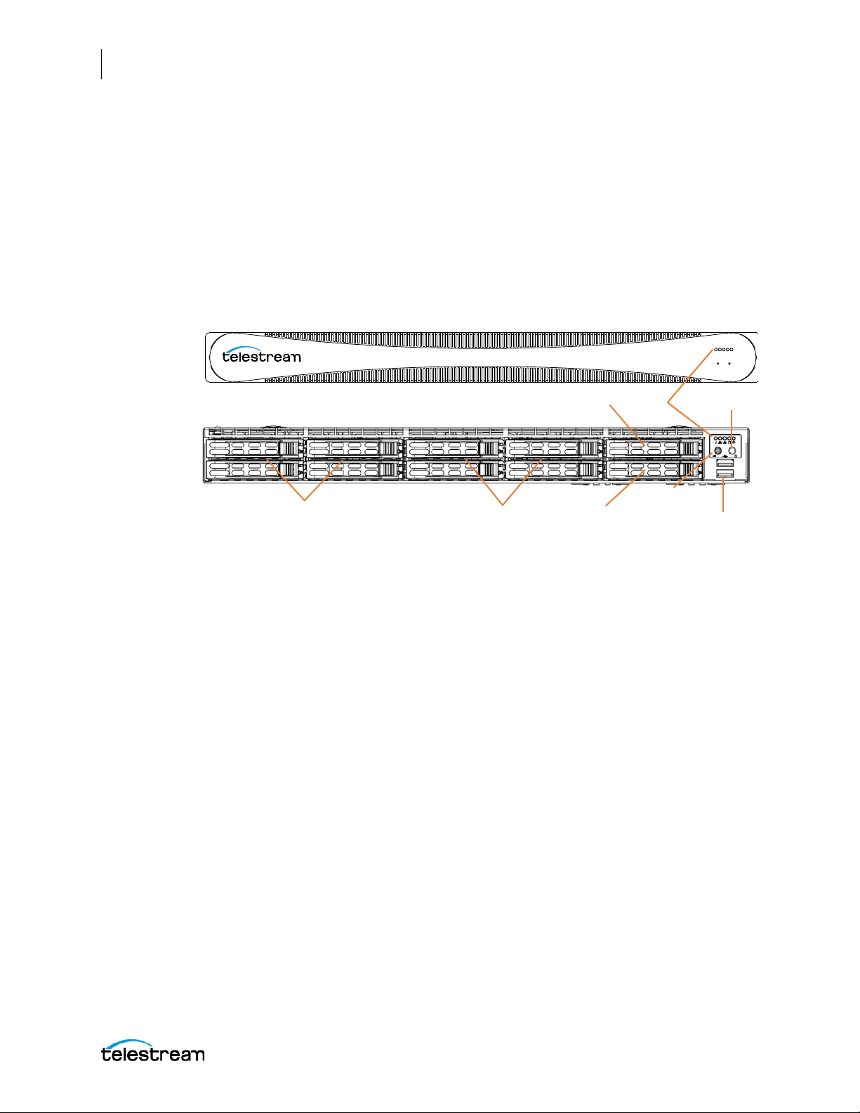
22
Lightspeed Live
LEDs On/Off Button
2 USB 3.0
SSD/SATA OS Drive
4 Included RAID 5
SAS Drives
4 RAID 5 SAS
Available Drive Bays
Available SSD or
SATA Drive Bay
UID Button
Introduction
Lightspeed Live Server
Front Panel
The Lightspeed Live server has a removable front bezel. By removing the bezel, you can
access the system interface buttons and LEDs, drives, and 2 front USB ports.
Front Panel Features
The removable front bezel provides visibility of the system monitoring LED indicators
and allows pinhole access to the recessed UID and power buttons.
Lightspeed Server Front Bezel:
LEDs (left to right)
• System Overheat | FAN Fail | UID
• Network Activity (NIC1)
• Network Activity (NIC2)
• Hard Drive Activity
• Power
UID Button (left)
The UID button alternately turns on and off the blue front and rear panel UID LEDs used
to locate a particular unit among many units in a rack or server room.
Power On/Off Button (right)
Press the Power On/Off button to perform a normal power up/power down cycle or a
hardware reboot (hold the button down for 4 seconds). A reboot abnormally
terminates connected clients and systems and should be done only in the event of an
unrecoverable system error. Under normal conditions, you should properly close client
programs and shut down the domain and OS before cycling power.
USB Ports
Two USB 3.0 ports for general use are located below the LEDs and buttons.
Lightspeed Live Guide
Page 23
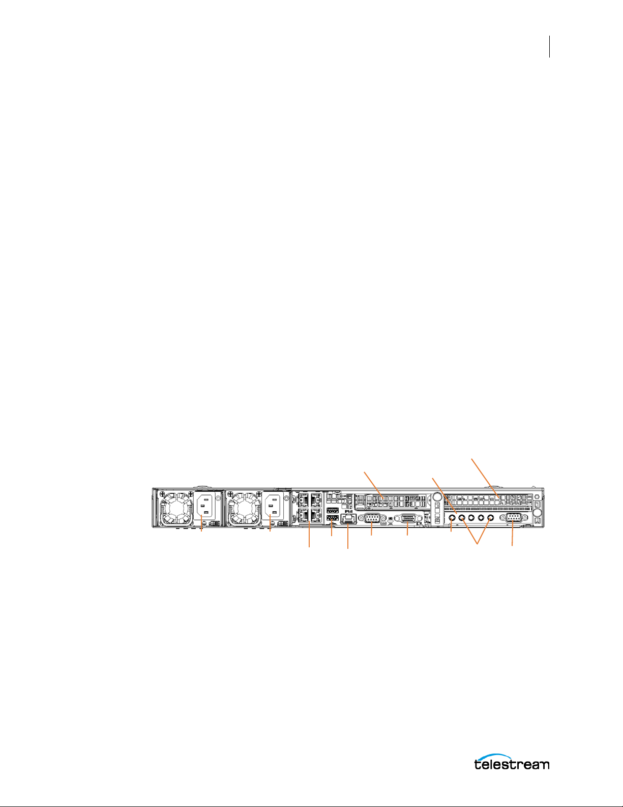
Drives
AC Power Connectors
1 PCI half height x8
expansion slot for
Telestream approved
cards only
4 Onboard 10Gb
Ethernet LAN ports
IPMI port
(dedicated)
2 USB VGACOM
4 mini-BNC
SDI Inputs
Unused
LTC
SDI input Card
GPU Card
The top right-most drive bay houses the SSD/SATA Windows OS drive, and the drive
beneath it is an available SATA drive bay. These drives have their own controller,
separate from the storage drives.
To the left of the OS drive are 8 SAS media storage drive slots containing the 4 standard
and 4 optional media drives. These drives are configured for RAID 5 and have their own
controller separate from the OS drive.
Rear Panel
These are the rear panel ports and connectors:
Introduction
Lightspeed Live Server
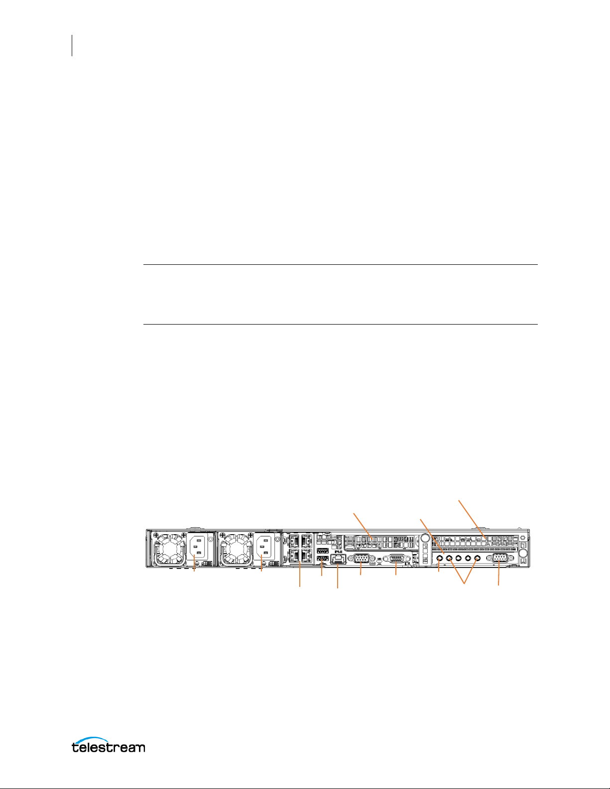
• 2 redundant AC power connectors—connect to a 10-amp or greater AC source
• 4 10GbT Ethernet LAN ports—connect as required to Ethernet LAN
• 2 USB 3.0 ports—connect as required to keyboard, mouse, or other serial device
• 1 IPMI Ethernet dedicated port that should not used for any other purpose
23
• 1 VGA monitor port
• 1 COM control port (not used)
• 4 3G-SDI inputs
• 1 LTC input
Lightspeed Live server Rear Panel:
Additional PCI cards can be optionally installed by Telestream in the PCI expansion
slots.
Lightspeed Live Guide
Page 24

24
Introduction
Lightspeed Live Server
Video Input Connections
The Lightspeed Live server includes an installed standard SDI input card (included) or
an optional HEVC SDI input card in the lower right PCI slot. For a complete list of video
formats, see the SDI Input Cards.
Standard SDI Input Card
The standard SDI input card contains 5 miniature BNC video input connectors with 5
adapter cables to convert to full-size BNC connectors:
• SDI Inputs 1-4: SD/HD/3G x 1080/4K video formats; audio 16-Channel, 24-bit SDI
embedded, 48 kHz synchronous
• Input R: LTC timecode input
Optional HEVC SDI Input Card (Supported by Live Stream only)
The HEVC option card replaces the standard SDI input card and contains 5 full-sized
BNC video input connectors:
• SDI Inputs: SD/HD/3G x 1080/4K video formats; audio 16-Channel, 24-bit SDI
embedded, 48 kHz synchronous
• LTC T im ec od e In pu t: The BNC connector on the bottom of the board. On the far
right in the picture below
Lightspeed Live Guide
Page 25

Server Installation and Maintenance
This chapter explains how to install the Lightspeed Live server into an equipment rack
and configure it for operation.
This chapter covers the following topics:
■ Installing the Server
■ Making Connections
■ Operating System
25
■ Maintaining the Server
■ Monitoring Lightspeed Live via SNMP
Page 26

26
Server Installation and Maintenance
Installing the Server
Installing the Server
The following topics cover physical server installation:
■ Unpacking
■ Rack Installation
WAR NING : Only trained and qualified personnel should be allowed to install, replace, or
service this equipment.
CAUTION: Except for replaceable power supplies and hard drives which may be
accessed from the outside, the Lightspeed Live server is a sealed device, with no userserviceable parts or user-accessible expansion slots. You should never open the top
cover or attempt to upgrade or alter the server. Doing so exposes you to electrical
hazard, may damage the unit, and may invalidate your warranty. If you have hardware
or software problems with your Lightspeed Live server, follow the steps in Obtaining
Support | Information | Assistance in Appendix B of this guide to obtain service.
Note: Before proceeding, work with your network administrator to determine
computer and network setting requirements.
Unpacking
The Lightspeed Live server comes packed in a heavy duty cardboard box with foam
padding surrounding the device to protect it. During unpacking, inspect the container
and the contents for damage. If there is any damage, report it immediately to the
freight carrier and to Tel est r e am Support.
The computer is heavy. Unpack the computer on a strong, well-balanced table that can
support the full weight of the computer and shipping container without tipping.
Inside the box, you will find the computer, optional components such as rack rails, five
mini BNC to standard BNC cables, and documentation on paper and flash drive (a DVD
is available by request).
Lightspeed Live Guide
Page 27
Rack Installation
The Lightspeed Live server is designed to fit into a standard 19-inch (483 mm)
equipment rack with support front and rear, using supplied rack rails and rear support
extensions.
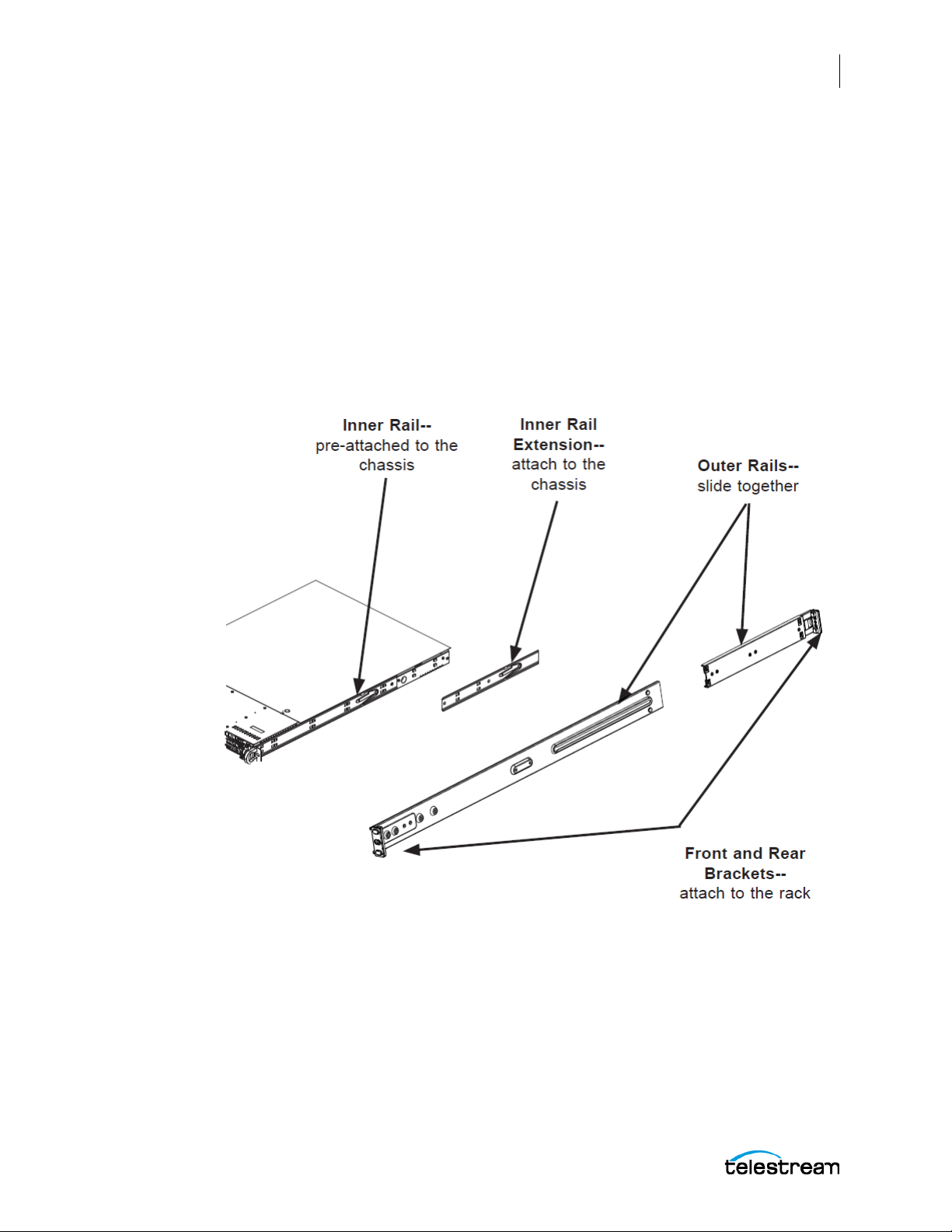
Assembling the Rails
The inner rail extensions install on each side of the chassis as shown. Align the
extension’s holes with the hooks on the side rail and slide the extension forward to
engage the hooks until the quick release bracket snaps into place. For added stability,
you can secure the extension with a screw.
The outer rails assemble by sliding the front and rear sections together as shown.
Server Installation and Maintenance
Installing the Server
27
Lightspeed Live Guide
Page 28

28
Server Installation and Maintenance
Installing the Server
Installing Outer Rails into a Rack
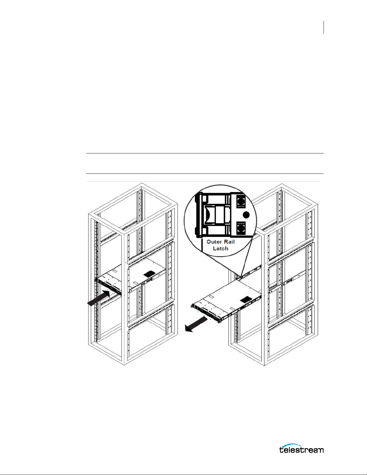
Next, install the outer rails into the rack as shown in the next figure. Align the square
pegs on the front of the rail with the square holes in the front of the rack (C).
Push the rail into the rack until the quick release bracket snaps into place, securing the
rail to the rack.
Extend the rear of the rail to align its square pegs with the square holes on the rear of
the rack (D). Push the rail into the rack until the quick release bracket snaps into place,
securing the rail to the rack.
CAUTION: To prevent the server chassis from falling and becoming damaged, be sure
the rails are solidly in position and ready to support the full weight of the chassis.
Lightspeed Live Guide
Page 29
Server Installation and Maintenance
Installing the Server
Installing the Server in the Rack
When selecting a position in a rack to place the server, be sure to allow a minimum of
30 inches of clearance at the back of the server for sufficient cooling airflow and
servicing.
To install the server, follow this procedure:
Slide the inner rail extensions forward into the front of the outer rails.
Support the chassis and align the back of the chassis with the front of the rails.
Push the chassis backward, sliding it into the rack rails, until the chassis clicks into the
locked position.
CAUTION: To prevent the server from falling and becoming damaged, be sure it is
securely in the rack before you remove support.
29
If you need to remove the server from the rack, press the outer rail latch shown in the
figure to release the chassis.
Slide the chassis forward off the outer rails and out of the chassis.
Lightspeed Live Guide
Page 30
30
AC Power Connectors
1 PCI half height x8
expansion slot for
Telestream approved
cards only
4 Onboard 10Gb
Ethernet LAN ports
IPMI port
(dedicated)
2 USB VGACOM
4 mini-BNC
SDI Inputs
Unused
LTC
SDI input Card
GPU Card
Server Installation and Maintenance
Making Connections
Making Connections
This topic describes the server’s connectors and how to connect to them. Follow the
order of connections given here:
■ Data and Signal Connections
■ Power Requirements and Connections
Data and Signal Connections
Make the following data and signal connections at the back of the server unit:
• Make Ethernet LAN connections to provide network connectivity.
Note: The Lightspeed Live Stream server can generate large amounts of network
traffic when actively streaming. To prevent possible network issues, consult with your
IT administrator to determine the best network configuration for your environment.
GIR-13121
• Connect devices, such as a keyboard and mouse, to the USB connectors (optional).
• Connect a dedicated IPMI LAN to the IPMI port (optional).
• Connect a monitor to the VGA connector (optional).
• Connect SDI video sources to the connectors on the SDI input card using the sup-
plied mini-to-BNC SDI cables.
• Connect a source of timecode (LTC) to the R (leftmost) BNC connector on the SDI
input card.
Lightspeed Live server Rear Panel:
Lightspeed Live Guide
Page 31

Power Requirements and Connections
After the server chassis has been physically installed and all other connections made,
connect the two redundant AC power cords to the back of the chassis and to an AC
power source. Be certain to observe the following AC power and connection
requirements and all applicable electrical codes.
The Lightspeed Live server is rated at 100-240 VAC, 50-60 Hz, up to 10 amps. Take the
following precautions to ensure a safe power connection:
• Make certain that the power source circuit can supply voltage within the specified
range and current of at least 10 amps without becoming overloaded.
• Counted together, the server and other devices connected to the same power
source must not exceed the total capacity of the power source circuit.
• To protect against circuit overload and overheating, ensure that the power source
circuit includes a circuit breaker no greater than 250 Volts, 20 Amps.
When power is connected, press the Power On/Off (0/1) button on the front of the
chassis to turn the server on. To turn power off at any time, press the Power On/Off
button again.
Server Installation and Maintenance
Making Connections
31
Power and General Cautions and Warnings
Observe the following precautions when connecting power and operating the server.
WAR NING : Only trained and qualified personnel should be allowed to install, replace, or
service this equipment.
WAR NING : Hazardous voltage or energy is present on the backplane when the system is
operating. To prevent possible injury or death, use caution when servicing.
WAR NING : This product relies on the building's installation for short-circuit (overcurrent)
protection. Ensure that the protective device is rated not greater than 250 Volts, 20 Amps.
WAR NING : Ensure a proper earth ground connection to the ground conductor in the AC
power plug. Failure to do so could present a severe electric shock hazard that could result
in injury or death.
CAUTION: Telestream recommends connecting computer equipment to AC power
through an uninterruptible power supply (UPS) with surge protection. Fluctuations in
commercial supply voltage can damage unprotected electronic equipment. A high
quality surge suppressor may be substituted if a UPS is not available, but it may not
provide adequate electrical spike protection.
Lightspeed Live Guide
Page 32

32
Server Installation and Maintenance
Making Connections
WAR NING : When installing the product, use the provided or designated connection
power cables. Using any other cables could cause a malfunction or a fire.
WAR NING : The fans might still be turning when you remove the fan assembly from the
chassis. Keep fingers, screwdrivers, and other objects away from the openings in the fan
assembly's housing.
WAR NING : Power supplies and other components can get very hot. Use caution when
touching possibly hot components during operation and directly after unplugging.
WAR NING : This unit has two power supply connections. Both connections must be
removed to completely de-energize the unit.
Lightspeed Live Guide
Page 33

Operating System
Windows Server 2012 R2 (Standard 64-bit) is pre-installed on the Lightspeed Live server
on an SSD drive. See microsoft.com
Microsoft Activation Key
A sticker on the top surface of the Lightspeed Live server lists license numbers. The
number listed as the Physical Key is the OEM license number for the Microsoft Windows
operating system. If you remove and reinstall the OS, you will need to use this key to
activate Windows again. The number typically contains five groups of five digits, as in
this example: YFG8H-TDD97-6BR4G-F88PF-XXXXX. Enter the Physical Key shown on
your sticker when activating Windows.
Microsoft Updates
The Lightspeed Live server ships with the Windows operating system set to check for
updates, but it does not automatically download or install them. Downloading and
installation of critical operating system updates is the responsibility of each customer
(see your system administrator).
for OS specifications.
Server Installation and Maintenance
Operating System
33
Windows User ID and Password
After the Lightspeed Live server boots up, you can log into it with the following
Windows user account.
:
Lightspeed Server Windows User Account
User Administrator
Password telestream!1
Windows Firewall
The Lightspeed Live Capture web application uses port 8083 and/or 8084, and Live
Stream uses port 8089. If you use Windows Firewall, be sure those ports are open on the
Lightspeed Live server and across your network.
To open the Windows firewall on the Lightspeed Live server or other Windows
machines, go to Start > Control Panel > Windows Firewall > Allow a program or feature
through Windows Firewall > Allow another program.
Scroll through the list of programs, and click Add for each of these: Lightspeed Live
Capture, Lightspeed Live Stream, Vantage Management Console, and Vantage
Workflow Portal.
Click OK to close the programs list. The added programs appear in the firewall list, and
you can check which networks they can use. Then close the Control Panel.
Lightspeed Live Guide
Page 34

34
Server Installation and Maintenance
Maintaining the Server
Maintaining the Server
The following section describes common server maintenance tasks that you may need
to perform from time to time:
■ Performance Tuning a Lightspeed Live Server
■ Backing up the Lightspeed Live Server
■ Managing the Lightspeed Live Server
■ Installing New or Replacement Hard Drives
■ Rebuilding the Lightspeed Live Storage RAID
■ Replacing Power Supplies
■ Monitoring Lightspeed Live via SNMP
Performance Tuning a Lightspeed Live Server
The following settings are made at the factory to ensure best performance of your
Lightspeed Live server. The settings are supplied here in the event they have been
changed and you need to restore them to factory original settings. (For details, consult
your System Administrator or a Telestream Field Sales Engineer).
1. In Performance Options, set Windows Performance options:
– Navigate to Start > Control Panel > System > Advanced system settings >
Settings > Advanced.
– Select Background services for Vantage transcoding nodes and SQL nodes.
– Select Programs for editorial systems and Vantage client applications that are not
running other Vantage services.
2. In Performance Options, Data Execution Prevention tab:
– Select Turn on (select) Data Execution Prevention (DEP) for essential Windows
programs and services only.
3. Set User Account Control (UAC) (in Start > Control Panel > User Accounts > Change
User Account Control Settings) as low as safely possible, considering your exposure
to Internet viruses and malware.
4. Set Power Options to High Performance with Sleep disabled:
– Navigate to Start > Control Panel > Power Options.
– Select the High Performance plan.
– Set Sleep mode to Never (never sleep).
– Select Change advanced power settings, and set all critical functions so that they
are always ON (this usually means setting them to Never turn OFF).
Lightspeed Live Guide
Page 35

Server Installation and Maintenance
Maintaining the Server
5. Disable (turn OFF) any real-time software applications and processes, such as the
following, that could adversely affect disk I/O performance or use excessive CPU:
– Real-time virus scanning of media files as they are being captured
– Automatic software updates that can preempt real-time services
– Real-time file indexing
6. Disable all unnecessary Windows services in the Start > Control Panel >
Administrative Tools > Services (consult your System Administrator).
7. Turn OFF all firewalls (including third party firewalls) and packet filtering, which may
cause unpredictable performance:
– Set Start > Control Panel > Windows Firewall > Turn off Windows Firewall.
If you choose to use firewalls, open them for the applications installed on the Lightspeed Live server.
8. You may increase network throughput by increasing buffer size within your
network adapter. Set your Network Adapter’s transmit and receive buffers to 1024:
– Start > Control Panel > Network and Sharing > Change Adapter Settings > Local
Area Connection > Properties
35
9. Disable any screen savers in Start > Control Panel > Display > Screen Savers.
10. Disable disk indexing in Start > Computer. Right-click each disk and uncheck Allow
files on this drive to have contents indexed in addition to file properties.
Backing up the Lightspeed Live Server
In order to protect your Lightspeed Live server from data loss, Telestream highly
recommends that you create an image of the Operating System drive (C:\) drive
immediately upon taking delivery of your server and that you perform periodic backups of all critical data on the server.
Several disk image software solutions are available for creating a restoration image that
you can use to restore the Lightspeed Live server's operating system drive (C:\) to its
original state. Using software solutions such as these, along with regular backups, you
can restore your server back to its original shipping state with all of your critical data:
• Norton Ghost
• Clonezilla
Consult your IT/Systems administrator for details on creating restoration images and
performing a periodic backup of your Lightspeed's critical data.
Lightspeed Live Guide
Page 36

36
Server Installation and Maintenance
Maintaining the Server
Managing the Lightspeed Live Server
IPMI View management software provides remote network management of one or
more Lightspeed or Lightspeed Live servers using IPMI messages over Ethernet LAN or
a dedicated IPMI LAN. If your Lightspeed Ethernet connectors are used to connect to
storage, you can use the IPMI LAN connector to create an IPMI network among your
Lightspeed servers.
You can download IPMI View from this location:
ftp://ftp.supermicro.com/utility/IPMIView/.
You’ll find the IPMI View User’s Guide at this location:
ftp://ftp.supermicro.com/utility/IPMIView/IPMIView20.pdf
Among the tasks you can perform using IPMI View are these (see the IPMI View User’s
Guide for details):
• Discover Lightspeed Servers on the IPMI network (requires dedicated IPMI LAN)
• View system event logs
• Check current sensors and monitor history of fans, voltages, temperature, and
power supplies
• View firmware revision levels
• Perform various kinds of shutdowns and resets
• Blink the UID LED to locate a particular unit in the rack or server room
• Set fan speed
• Manage LAN configuration, SNMP configuration, and RS232 modem
• Manage users, passwords, and privileges
• Set up paging of users in the event of malfunctions
• Establish Text Console Redirection or KVM Console Video Redirection for remote
system control via text display or full graphic display
• Access virtual media
• Set up server management groups
• Update firmware
For detailed instructions about using any of these system management features,
consult the IPMI View User’s Guide.
Lightspeed Live Guide
Page 37

Installing New or Replacement Hard Drives
Follow these steps to replace a failing hard drive or install a new one. Drives may be
removed or replaced with power on. See the Drives topic in the Introduction chapter for
new or replacement drive specifications.
1. Remove the front bezel from the chassis.
2. Press the release button on the right front of the drive carrier.
3. Use the drive carrier handle to pull the carrier out of the chassis.
Server Installation and Maintenance
Maintaining the Server
37
4. Remove the drive or dummy drive from the carrier by removing the four M3 screws
from the underside of the carrier. Retain the screws.
5. Insert the new drive into the carrier with the PCB side down and the connector
facing the back of the carrier.
6. Secure the drive to the carrier with the four M3 screws retained from removal.
Gently tighten but do not over tighten the screws, which could cause damage.
7. Slide the drive carrier into its bay with the drive facing up until the drive seats firmly
in the rear connector.
8. Push the carrier handle closed flat against the front of the carrier to secure the
carrier and drive in place.
9. Replace the front bezel on the chassis, and go to the next topic to rebuild the RAID.
Lightspeed Live Guide
Page 38

38
Server Installation and Maintenance
Maintaining the Server
Rebuilding the Lightspeed Live Storage RAID
MegaRAID Storage Manager software on the Lightspeed Live server desktop enables
you to rebuild the storage RAID if necessary, such as when you add a new drive. Simply
double-click the MegaRAID Storage Manager desktop icon to run the software.
Help instructions for using the MegaRAID Storage Manager software are located here:
C:\Program Files (x86)\MegaRAID Storage Manager\docs\msmHELP.
Follow the directions provided for configuring a new virtual drive for RAID 5.
Replacing Power Supplies
The Lightspeed Live server includes two redundant, hot-pluggable power supply
modules. They automatically sense the input voltage between 100v to 240v, and
operate at that voltage. Power cords plug directly into the power supply units at the
back of the chassis. A green light indicates that the power supply is operating. When a
power supply fails or loses power, an amber light on the power supply illuminates and
an alarm sounds.
If either of the power supply modules fail, the other module will support the full load
and will allow the system to continue operation without interruption. The PWR Fail LED
will illuminate and remain on until the failed unit has been replaced. Replace with the
same model. Replacement units can be ordered from Telestream. See Obtaining
Support | Information | Assistance.
Replacing the Power Supply
1. Unplug the AC power cord from the failed power supply module.
2. Push in the locking tab at the back of the module to release it.
3. Pull the unit straight out of the chassis.
CAUTION: the power supply may be very hot when first unplugged and could cause
burns. Handle carefully by the edges and do not touch hot components.
4. Insert the new unit into the chassis, pushing it in until it clicks firmly in place.
5. Reconnect the power cord.
Lightspeed Live Guide
Page 39

Server Installation and Maintenance
Monitoring Lightspeed Live via SNMP
Management Information Base (MIB) files are provided for those organizations wanting
to manage their Lightspeed Live servers via SNMP.
MIB files can be found on the Lightspeed Live server in this location:
C:\Program Files\Telestream\Live Stream Server
MIB files can also be found on the Lightspeed Live DVD or USB thumb-drive in the
SNMP folder.
39
Monitoring Lightspeed Live via SNMP
Lightspeed Live Guide
Page 40

40
Server Installation and Maintenance
Monitoring Lightspeed Live via SNMP
Lightspeed Live Guide
Page 41

Configuring and Updating Live Capture
This chapter explains how to configure the Lightspeed Live Capture software, and how
to update your server and install a ComponentPac update.
These are the topics that will help you configure the software:
■ What Is Lightspeed Live Capture?
■ When is an Array License Needed?
■ Warning: Do Not Remove the Stream Application
41
■ Configuring Settings for Your Facility
■ Configuring Ingest Sources
■ Creating a Live Capture Workflow
Once these settings and workflows have been completed, you’ll be ready to log into
the Lightspeed Live Capture web application and begin using it as explained in The
Lightspeed Live Capture Web Application chapter.
This chapter also covers configuration tasks for customizing your Lightspeed Live
Capture server, joining multiple servers together, and updating your server and
software:
■ Live Capture Server Configuration Changes
■ Updating Your Server using Secured Version Control and ComponentPacs
■ Clear Browsing Data after Updating Vantage or Live Capture
Page 42

42
Configuring and Updating Live Capture
What Is Lightspeed Live Capture?
What Is Lightspeed Live Capture?
Lightspeed Live Capture uses a variety of codecs and format containers to capture live
video into media files. Lightspeed Live Capture is designed to run standalone, or it can
operate as a part of a larger Vantage Media Processing Platform array.
At the simplest level, Lightspeed Live Capture consists of customizable workflow
actions that automate the live capture process. A workflow is the mechanism you
create that performs tasks automatically. The workflow is made up of individual tasks
called actions, which specify what task needs to be performed. In the case of
Lightspeed Live Capture, the main action is the Live Service's Capture action.
A typical capture workflow contains actions to do some or all of the following:
• Discover video sources connected to the Lightspeed Live server video inputs
• Capture live inputs into files containing video and audio
• Capture live video and audio into output files, both high resolution and proxy reso-
lution
• Deliver the captured files to a location you specify
Before a Lightspeed Live Capture workflow can operate as described above, you must
first configure Lightspeed Live Capture as follows:
• Install licenses, if not already installed at the factory
• Create user accounts to access the Lightspeed Live Capture tools
• Create Live storage locations for captured and proxy files, if not factory defined
• Add Capture Channel group(s)
• Configure all input sources
• Create your Capture workflows
The program used to configure these things is the Vantage Management
Console, which has an icon on your desktop. Later in this chapter we will
guide you in using the console to do the necessary configuration.
After configuration, the next step is to create and hook up the Capture
workflow. Workflows are designed using a software tool called the Vantage
Workflow Designer, which is also launched from a desktop icon. We will guide you step
by step in creating and activating a simple Capture workflow that will detect your
sources, encode them, and place your captured files into a storage location.
Once your Capture workflow is activated and online you're ready to start capturing.
Capture control is done in a web application called the Lightspeed Live Capture web
application. The Lightspeed Live Capture Web API can also be used to control
operations.
This chapter covers Vantage Management Console and Workflow Designer
configuration. Using the Lightspeed Live Capture web application is covered in a later
chapter.
Lightspeed Live Guide
Page 43

Configuring and Updating Live Capture
When is an Array License Needed?
When is an Array License Needed?
Users can cluster multiple Lightspeed Live servers together and run captures on each
machine without an array license when workflows have all actions within a workflow
running on the same machine.
For example, you can cluster two Lightspeed Live servers together, have all channels
appear in the same Nexus and have each server capture its own SDI inputs at the same
time. In this example, an array license is not needed.
An array license is needed when, for example, the capture workflow contains a Flip
action, which requires at least two servers: one server for the capture and a second
server for the transcode. When a workflow contains multiple actions running on
different servers, then an array license is needed.
See Joining Multiple Capture Servers for information about setting up an array.
Warning: Do Not Remove the Stream Application
43
Do not uninstall the Lightspeed Live Stream application. Components of the Live
Stream application are needed in order for Capture to operate properly.
Lightspeed Live Guide
Page 44
44
Configuring and Updating Live Capture
Configuring Settings for Your Facility
Configuring Settings for Your Facility
A few settings are required on your Lightspeed Live server before you launch the
Lightspeed Live Capture web application. Some of these settings are configured at the
factory, but you should verify them and make additional custom settings as follows:
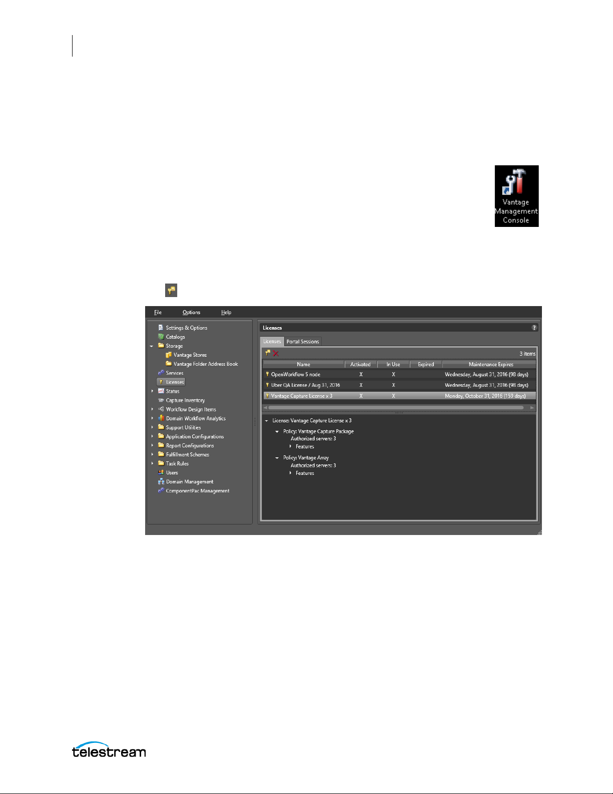
1. Launch the Vantage Management Console by double-clicking the
desktop icon.
(To learn more about any of the following steps, click the question mark
(?) in the upper right corner of the Console to open the searchable Van-
tage Domain Management Guide.)
2. Apply your Lightspeed Live Capture license by clicking Licenses in the left panel and
verifying that you have a Live Capture license.
If not, contact Telestream for a license, and click the Add/Update a License button
in the Licenses panel to add the new license.
Lightspeed Live Guide
Page 45
Configuring and Updating Live Capture
Configuring Settings for Your Facility
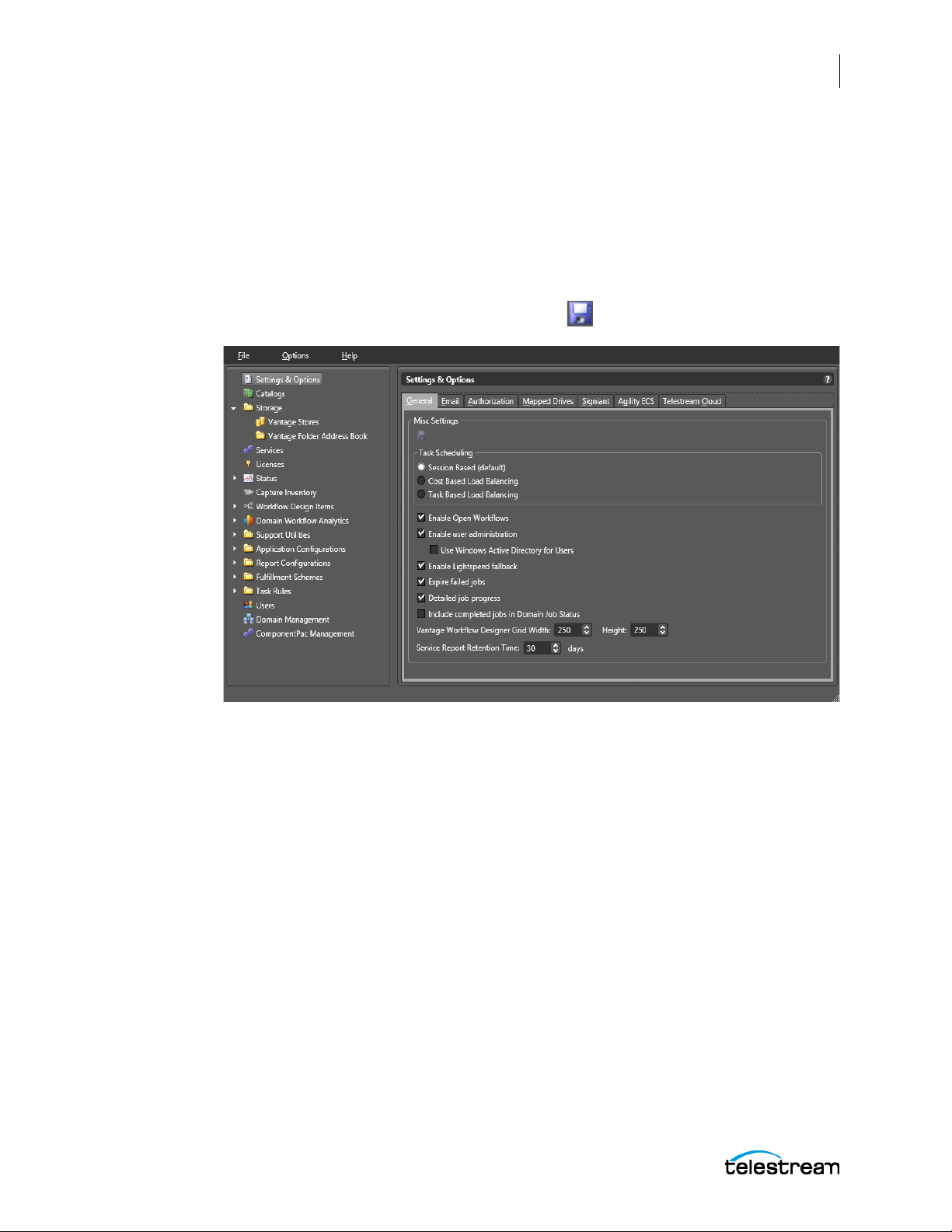
3. Activate User Administration (or verify that it was activated at the factory.) Select
Settings & Options in the left panel. On the General tab, verify that Enable user
administration is selected, and if not, select it. This must be enabled in order to use
the Lightspeed Live Capture web application.
You may also want to check Use Windows Active Directory for Users to use your Windows logins for Vantage. Alternatively, you can create Vantage-only users if you
leave the Windows option unchecked.
If you made any changes, click the Save icon .
45
Lightspeed Live Guide
Page 46
46
Configuring and Updating Live Capture
Configuring Settings for Your Facility
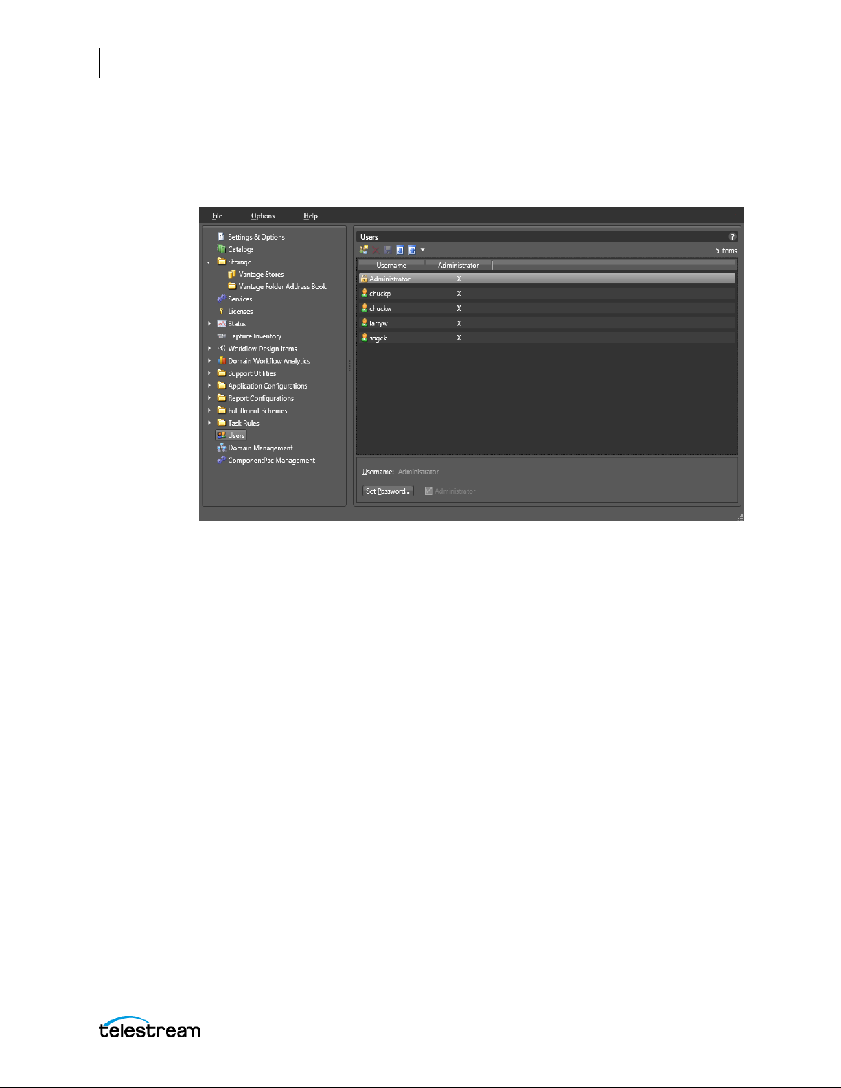
4. Create user accounts for Lightspeed Live Capture. Select Users near the bottom of
the left panel to create new user accounts. To add a new account, click the New User
button in the Users panel and fill in the form. Each Capture user should have a
login.
Lightspeed Live Guide
Page 47
Configuring and Updating Live Capture
Configuring Settings for Your Facility
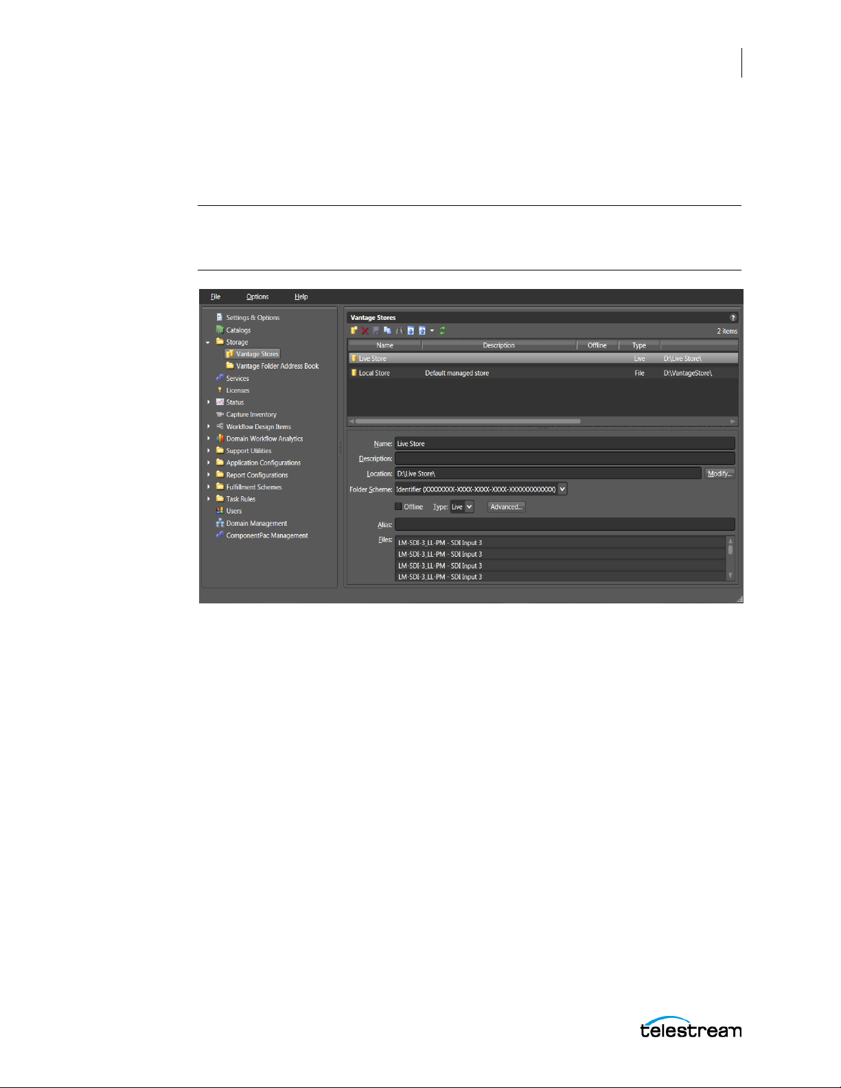
5. Add a live capture store (or verify that it has been added at the factory). Select
Storage > Vantage Stores in the left panel and verify that a Live Store exists in the
D:\Live Store\ location. If not, click the New Vantage Store icon, fill out the form, and
be sure to select Type: Live in the form.
Note: You may need to specify the storage location as a UNC path instead of the
default D:\Live Store location, especially if you have multiple servers connected
together in an array. A UNC path looks like this: \\hostname\d\Live Store.
47
Lightspeed Live Guide
Page 48
48
Configuring and Updating Live Capture
Configuring Ingest Sources
Configuring Ingest Sources
Before the channel groups and sources can be accessed by the Lightspeed Live Capture
web app and transformed into the captured output files, they need to be defined. This
allows the system to work with the sources according to your workflow and Lightspeed
Live Capture web app configurations. The workflows and Live Capture web app work
together, and the beginning of the inter-operation is to define nexus channel groups
and source inputs.
Configuring a Channel Group Nexus
A nexus is a connection point to a group of associated workflows. Lightspeed Live
Capture uses the concept of a nexus to group related video source channels together.
For example, one group of sources might be camera video feeds coming from the same
studio, and another group might come from another studio. A single source can be
referenced in multiple workflows and, hence, in more than one nexus. The Nexus
Definitions created here are called Channel Groups in the Lightspeed Live Capture web
application. See Selecting a Channel Group.
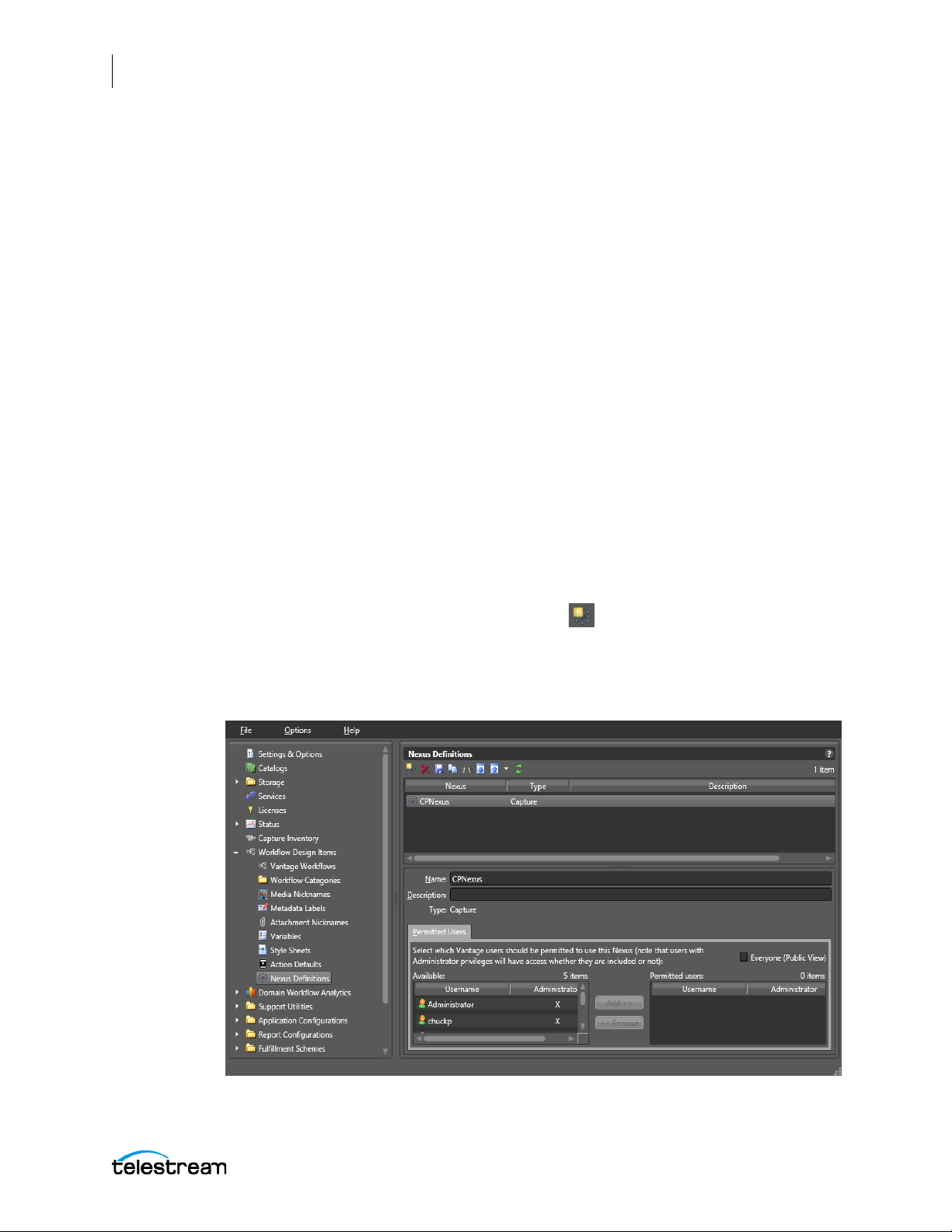
Follow these steps to configure a nexus and an inventory of video sources:
1. Launch the Vantage Management Console.
2. Select Workflow Design Items > Nexus Definitions in the left panel.
3. Use the Create a new Nexus definition button in the Nexus Definitions panel.
4. Select Capture in the dialog that opens, and click OK to add a new nexus.
5. In the Name field, type the name you want, and add optional information in the
Description field.
Lightspeed Live Guide
Page 49

Configuring and Updating Live Capture
Configuring Ingest Sources
6. In the Permitted Users section (visible only if User Administration is enabled in the
Settings & Options > General tab) you can assign Permitted Users by clicking on a
user in the left list, and clicking Add to move them to the right list. You can check
Everyone (Public Access) (this is the default) to allow all users access to that nexus.
Use Remove to move a selected user on the right to the non-permitted list on the
left. This disables that user’s access. Each nexus can have its own list of Permitted
Users.
The list of Available users is created by adding user accounts in the Users panel. See
Configuring Settings for Your Facility for instructions.
Note: Users with administrator privileges will have access whether they are included,
or not, in the Permitted Users list.
7. Click the Save button to save the changes and create a new channel group
nexus.
49
Lightspeed Live Guide
Page 50
50
Configuring and Updating Live Capture
Configuring Ingest Sources
Configuring SDI Sources
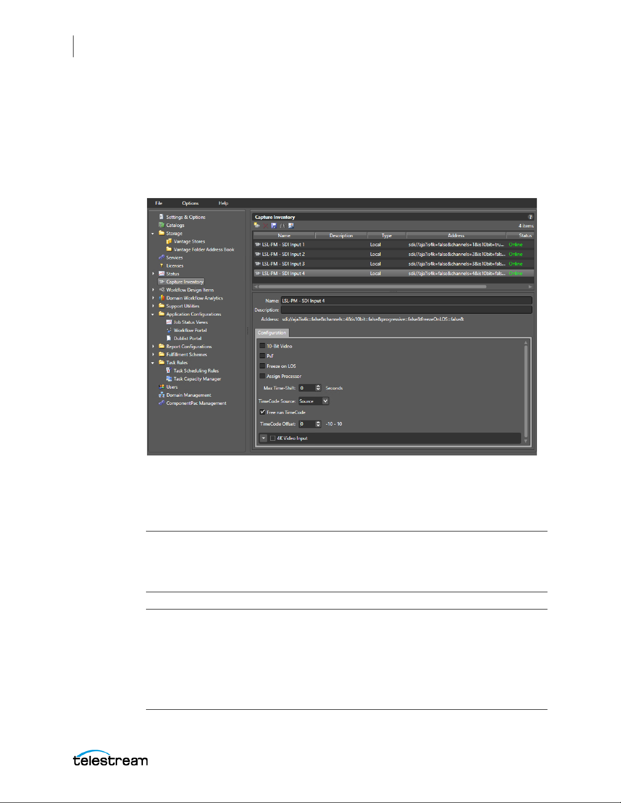
The options for SDI sources need to be configured in the Vantage Management
Console > Capture Inventory panel. SDI sources entering the Lightspeed Live server are
automatically added to the inventory list of sources.
Select Capture Inventory in the left panel to open the Capture Inventory panel for
editing.
When Live Stream and Capture are Used on the Same Server
The following Note and Warning apply only when Live Stream and Live Capture are
used on the same Lightspeed Live server:
Note: Changing sources in any way in the Capture Inventory window affects which
sources are available to the Capture and Stream web applications. Conversely,
changing source configurations in the Stream web application changes what is shown
in Capture Inventory.
WAR NING : When Live Stream and Live Capture are used on a server concurrently, any File
Loop, RTMP, Slate, or Transport Stream sources that appear in the Capture Inventory are
NOT supported for Capture workflows. Do not make any changes to the options for these
sources; they are created by and used by the Stream application. Configuration changes
for these sources are made in the Lightspeed Live Stream web application. The actual
name of the sources created in Live Stream can be any name they have been given, and
may not be called File Loop, RTMP, and so on.
Lightspeed Live Guide
Page 51
Configuring and Updating Live Capture
Configuring Ingest Sources
Previewing Sources
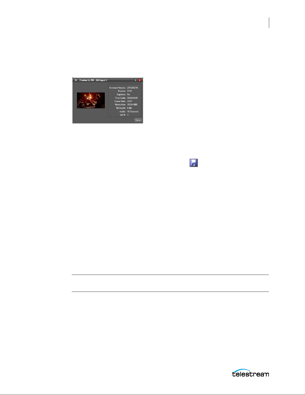
You can preview source video, and see information about it, in a small window (below)
by right-clicking the source and selecting Preview, or by using the Preview button in
the toolbar. The preview image is updated once per second.
Changing the Source Name
Default source names include the server name and input number. The default source
name has this form: “<ServerName> - SDI Input 1”.
To rename a source, select the source and change the name in the Name field of the
Capture Inventory panel, then click the Save button to save the changes. You can
also add information in the Description field for reference purposes.
51
When renaming a source, it is important to remember:
• If workflows exist that used the previous name, they will no longer be associated
with the new name. After changing a source name you must edit the affected Capture actions and select the newly named source you want to use.
• Each source must be named uniquely.
• None of these characters can be used in the source name: ` * | \ : ; " ' < > ? /
Configuring SDI Source Options
Select each source to configure the options uniquely for each input. The Configuration
panel lets you choose the following options for each source:
10 Bit Video—When checked, enables full 10 bit sampling of the video on the SDI
input. Using 10 bit sampling requires additional processing and should not be enabled
for Standard Definition (SD) sources.
CAUTION: When using an 8 bit leader, filler, or trailer along with the video, do not
select the 10 bit sampling mode. Corrupted output can result.
PsF—Check the PsF box if your incoming SDI source signal is formatted as PsF
(Progressive segmented Frame).
Freeze on LOS—When checked, will cause the incoming video signal to freeze on the
last frame if Loss of Signal (LOS) is detected. When unchecked, color bars are display on
LOS.
Assign Processor (SD/HD sources only)—When checked, all processing is assigned to
a single multicore CPU socket. This prevents inefficient mapping of processes across
CPU sockets during heavy loads, such as when all four inputs are being processed.
Lightspeed Live Guide
Page 52

52
Configuring and Updating Live Capture
Configuring Ingest Sources
Max Time-Shift—This value represents the maximum size of the Time-Shift frame
buffer (in seconds) for workflows using this SDI source. The recommended value is 30
seconds, or less, and is limited to no more than 60 seconds.
Note: Time-Shift—Live Capture’s Time-Shift allows you to hold incoming source
media frames in an internal FIFO buffer. You can choose to buffer up to 60 seconds of
media for each input on your Lightspeed Live server (some limitations may exist for
higher bit rates and frame rates). Caution should be taken when setting Time-Shift to a
value greater than 30 seconds on more than one input source. See Determining the
Time-Shift Buffer Duration for recommendations on settings for various frame sizes
and frame rates.
When a capture workflow is activated with Time-Shift enabled, the input’s source
media is stored in a FIFO buffer which allows Lightspeed Live to reach back in time and
access media processed in the past based on the value of the Time-Shift field. Since
Live Capture’s Time-Shift is always processing an input source’s media, when a record
is initiated any media stored in the Time-Shift buffer is available to be added to the
captured file.
TimeCode Source—Click the drop-down menu to choose one of the following
timecode source signals for the selected SDI input:
Source—Uses the timecode provided in VBI or VANC (SMPTE 12M-2/RP188) of the
selected Lightspeed Live Capture's video input signal. If a valid timecode is not
available or goes away – see the Free Run TimeCode option below.
Computer Clock—Uses the time-of-day clock provided by the Lightspeed Live
Capture Server.
Free Run—This timecode starts at 00:00:00:00 and free runs after the Capture
workflow associated with it is activated. The recorded timecode captured will
reflect the free run timecode at the time capture begins.
Analog LTC—Uses the timecode provided on the SDI card's LTC input (marked with
an R on the SDI card). If a valid timecode is not available or goes away – see the
Free Run TimeCode option below.
RS422—Uses the timecode provided by a VTR connected via RS-422.
Note: When using the Schedule Trigger you should set your TimeCode Source to
either Computer Clock or Source. When using Source, you must have time-of-day
timecode in your source that matches the time set in your Lightspeed Live server. See
Trigger Settings in Appendix A for Trigger configuration options.
Free Run TimeCode—When enabled, and the desired timecode is not detected or
goes away, the timecode will attempt to Free Run from the last timecode rec
eived.
When Free Run TimeCode is not enabled, and the desired timecode is not detected or
goes away, then the timecode will revert to zero (00:00:00:00) and stay at zero.
TimeCode Offset—TimeCode Offset can be used to compensate for VTR decks
requiring adjustments to frame timing. Frames can appear early or late, depending on
the type and/or age of the VTR deck used. This adjustment compensates for VTR decks
Lightspeed Live Guide
Page 53

Configuring and Updating Live Capture
Configuring Ingest Sources
that are not 100% frame accurate (or for systems with routing latency to the associated
timecode). Most VTR decks will not require this offset adjustment. If you have a VTR
deck that needs this adjustment it will be necessary to use a trial and error process to
determine the correct offset. The default is 0, the minimum is -10 frames, and the
maximum is +10 frames.
Note: TimeCode Offset only applies to RS-422 and Analog LTC timecode sources.
4K Video Input—When 4K Video Input is enabled (from any SDI source), the SDI input
card converts the 4 independent 3G SDI inputs into a single UHD/4K input. After
selecting the 4K Video Input, and saving this configuration change, Capture Inventory
will display one UHD/4K SDI source.
CAUTION: Be very careful when changing the 4K Video Input as Capture workflows
(or Live Stream configurations) that may be actively using one of the independent 3G
SDI inputs will not be able to use them when the inputs are coalesced into a single
UHD/4K SDI input.
53
Procedures to Switch Between HD and 4K Configurations
The key ingredient to enabling or disabling the 4K mode is that a valid and active UHD/
4K signal must be connected to the Lightspeed Live server during the switching in/out
of 4K mode process. To successfully switch from an HD configuration to a UHD/4K
input, and then back again, follow the procedures described below.
To switch from HD into UHD/4K input mode:
1. Deactivate all Capture action workflows that are actively running on any of the
server inputs.
2. Connect your 4K input cables to all four SDI input BNC connectors, from a valid
UHD/4K source.
3. Start your 4K source so that it is actively providing a signal to the Lightspeed Live
server.
4. Open the Capture Inventory panel of the Vantage Management Console, and select
SDI Input 1.
5. Check the 4K Video Input option, then click the Save button to save your changes.
6. The four inputs are now consolidated into one input and renamed to include “4K”
in the name.
7. In the Vantage Workflow Designer, for any workflow that you want to use the 4K
source, open the Capture action and select the new 4K input as the Source.
8. Make any other desired changes in the Capture action and Save it.
9. Click Activate below the workflow to initiate workflow operation.
To switch from UHD/4K into HD input mode:
1. The UHD/4K source needs to be actively providing a signal to the server.
2. Deactivate all Capture action workflows that are using the 4K input source.
Lightspeed Live Guide
Page 54

54
Configuring and Updating Live Capture
Configuring Ingest Sources
3. Open the Capture Inventory panel of the Vantage Management Console.
4. Uncheck the 4K Video Input option, then click the Save button to save your changes.
5. The inventory is now converted back to the default four SDI inputs.
6. Turn off your 4K signal source and disconnect the cables from the 4K device.
7. Connect HD source cables to one or more of the SDI input BNC connectors.
8. In the Vantage Workflow Designer, configure each Capture action to use any one of
the SDI inputs that you want for that workflow, and make any other desired
adjustments and save your changes.
9. Click Activate for each workflow that you want to place into operation.
Lightspeed Live Guide
Page 55
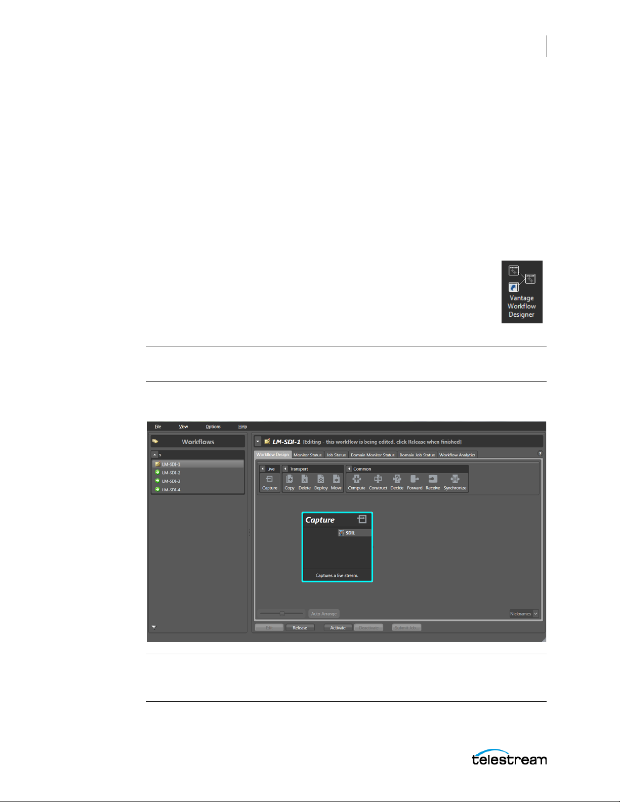
Creating a Live Capture Workflow
The next step in configuring the Lightspeed Live Capture system is to create a live
capture workflow. The workflow processes the input source you select, packages it into
the desired video and audio format, and delivers it to the desired storage location.
A simple workflow example with configuration instructions is shown below.
Consult the Vantage User Guide (click the question mark (?) in the upper right window
corner) for details about the functions you can use in workflows. For example, you can
use a Move action to move files from the Live Store to another location on your server,
or you can use a Deploy action to send files to multiple storage destinations or to social
media sites.
1. Launch the Vantage Workflow Designer by double-clicking the desktop
icon.
2. Select File > Create New Workflow and name the workflow. You may also
need to create a Category (File > Create New Category), which is a folder
where the workflow will be stored. The default workflow naming
pattern is [Workflow Name]_[Source Name].
Configuring and Updating Live Capture
Creating a Live Capture Workflow
55
Note: To avoid workflow failures, do not use these characters in workflow names:
` * | \ : ; " ' < > ? /
3. In the Workflow Design panel, select Live from the top tool bar and drag a Capture
action into the workspace below.
Note: Workflow expiration is set for 24 hours and is enabled by default. For details,
click the ? in the upper right to open the Vantage User Guide. See the Viewing and
Specifying Workflow Details topic for information on adjusting the expiration time.
Lightspeed Live Guide
Page 56
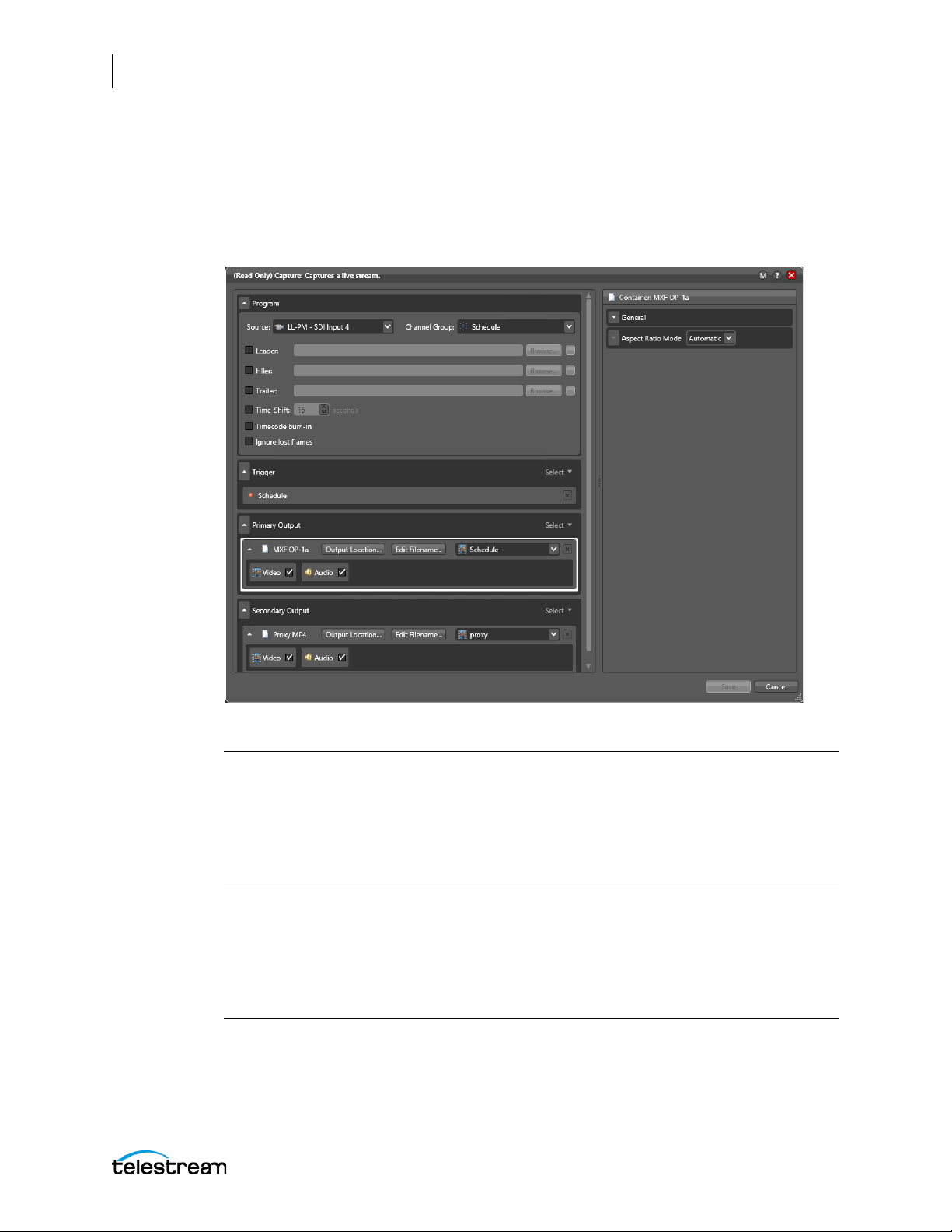
56
Configuring and Updating Live Capture
Creating a Live Capture Workflow
4. Select the Inspector (circled i) icon on the upper left corner of the Capture action to
open the Inspector and configure the action, or double-click the action to open the
Inspector.
5. Click Save when finished with your configuration settings.
6. Click Activate below the workflow to initiate workflow operation.
The following descriptions summarize the Inspector selections.
Note: To see detailed descriptions of selections, click the circled M in the upper right
window corner to open the help page. The Appendix A: Capture Action and Codec
Descriptions at the back of this guide includes the help pages describing the Capture
action and other related actions. You can also view the full guide for Workflow
Designer and learn about the available actions by clicking the ? to the right of the
circled M. See the Vantage Actions chapter for details.
Program section—Use the drop-down menus to select a Channel group and a live video
Source. You can also browse to add video from files to the live video, including a Leader
at the start of video, a Filler during capture, and a Trailer at the end of video. To enable
the Time-Shift feature, select Time-Shift. You can also burn-in timecode to the video if
you check Timecode burn-in.
WAR NING : Capture currently supports SDI inputs only. If your server is configured with
both Capture and Lightspeed Live Stream the 'File Loop', 'RTMP', 'Slate', or 'Transport
Stream' sources may appear in the Source drop-down menu. These are NOT supported for
use by Capture workflows and are reserved for Lightspeed Live Stream. Only select one of
Lightspeed Live Guide
Page 57

Configuring and Updating Live Capture
Creating a Live Capture Workflow
the SDI source inputs. The actual name of the sources created in Live Stream can be any
name they have been given, and may not be called File Loop, RTMP, and so on.
Trigger section—The trigger option sets how live capture sessions are triggered
(started), either by manually triggering from the Lightspeed Live Capture web
application, from a schedule, by controlling a VTR, or from the Lightspeed Live Capture
Web API.
Note: If you are using the Lightspeed Live Capture web app to control live capturing,
you must set the Trigger option to Manual or VTR so the web app can control the
recording of input channels.
Primary Output section—Use the Select menu to select a video output container format
for the captured file. You’ll also need to specify an output location for the captured file,
configure how the filename will be generated, and assign a nickname. Then check the
Video and Audio stream boxes and configure encoders in the right panel.
Secondary Output section—The optional secondary output is a proxy file. Settings are
similar to those for the Primary Output, however only the container formats and codecs
that are used for proxy files are available.
57
Note: For complete details on the Capture action options, see Capture Action in
Appendix A of this guide, or click the circled M in the upper right corner of the Capture
action window to open the help page.
The Monitor Status tab opens to show the progress of your workflow as it operates and
gives you information about it. You can double-click the line item representing your
workflow and get details about how it is functioning.
Lightspeed Live Guide
Page 58

58
Configuring and Updating Live Capture
Creating a Live Capture Workflow
When you activate a workflow, it begins to operate and work with the Lightspeed Live
Capture web application to accept the input you select, encode and package it into the
format you specified in the workflow, and output the captured media package to the
Live Store location you specified.
Adding other actions, such as Deploy, can enable your Vantage workflow to
automatically move the output from the store to another location or server for
downstream processing or broadcast.
There are many more ways to monitor your workflow. To learn more, click the ? icon or
use the Help menu to open the searchable Vantage User Guide. The ? opens to the topic
that matches the area of the user interface that you are using.
This completes configuration and a simple workflow as prerequisites for running the
Lightspeed Live Capture web app. You are now ready to log into the Capture web app
and begin using it as explained in The Lightspeed Live Capture Web Application chapter.
As you use the Capture web app, remember that it performs the way you want it to
because of the way you have set your workflow. If you want a different container
format, a different encoding, or a different storage location for your captured files, you
change those features by altering the workflow.
Lightspeed Live Guide
Page 59
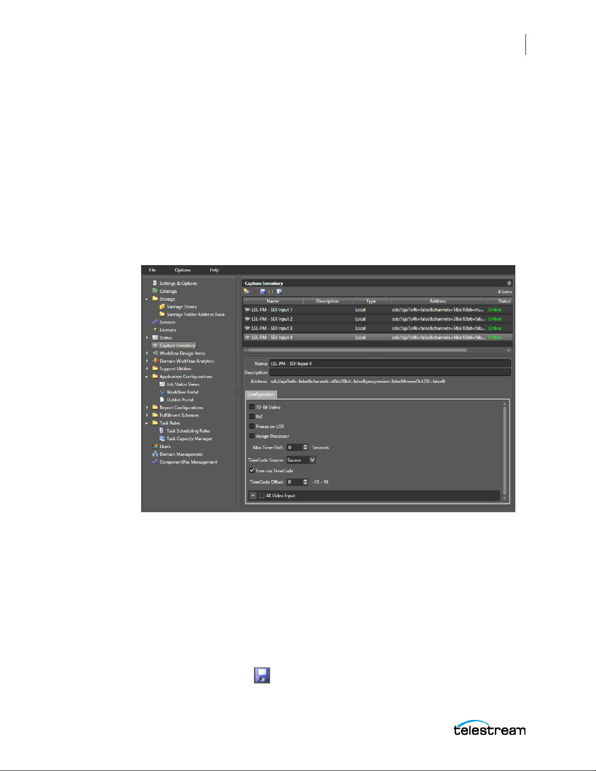
Creating a VTR Capture Workflow
When you want to capture video data from a VTR, the VTR must be properly connected
to the Lightspeed Live server and configuration settings need to be made in both the
Vantage Management Console > Capture Inventory panel and the Vantage Workflow
Designer > Capture action.
Follow these steps to create a workflow to capture VTR data:
1. Make sure the VTR is properly installed and connected to the Lightspeed Live
server. See Appendix B: Installing the RS-422 Interface Kit.
2. Power up the VTR and switch it into the proper Remote mode for RS-422 control.
3. Open the Vantage Management Console and select Capture Inventory in the left
panel to open the Capture Inventory panel for editing.
Configuring and Updating Live Capture
Creating a Live Capture Workflow
59
4. In the upper section, select the SDI Input you want to use for the VTR connection.
5. In the Configuration section select RS422 from the TimeCode Source drop-down
6. If the VTR deck requires adjustments to compensate for frame timing, you can use
7. Click the Save button to save the Capture Inventory changes.
Lightspeed Live Guide
This will need to be the one that matches the terminal number the VTR is
connected to on the RS-422 interface box. For example, when connected to
Channel 1 (CH1) on the RS-422 interface box you must select SDI Input 1in the
Capture Inventory.
menu.
TimeCode Offset to enter a frame adjustment. See Configuring SDI Source Options
for details of this option.
Page 60

60
Configuring and Updating Live Capture
Creating a Live Capture Workflow
8. Next, the Capture action needs to be configured. Launch the Vantage Workflow
Designer by double-clicking the desktop icon, then open the Workflow that is
associated with the input the VTR is using. If you need to create a new Workflow,
see Creating a Live Capture Workflow above for details.
9. Open the Capture action for editing and select VTR for the Trigger type.
10. Make any other desired setting choices, then click Save when finished with your
configuration settings.
11. Click Activate below the workflow to initiate workflow operation.
12. Once activated the Workflow's Monitor Status panel should return the status of
"Initializing: VTR connected" as shown in the following image.
If, instead, the status "Initializing: VTR not connected" is shown, proceed to the following section: Troubleshooting the VTR Connection.
When the VTR connection is successfully initialized, use the Live Capture web
application to set recording parameters and control the VTR to ingest media from tape.
See VTR Mode Controls and Indicators for instructions.
Lightspeed Live Guide
Page 61
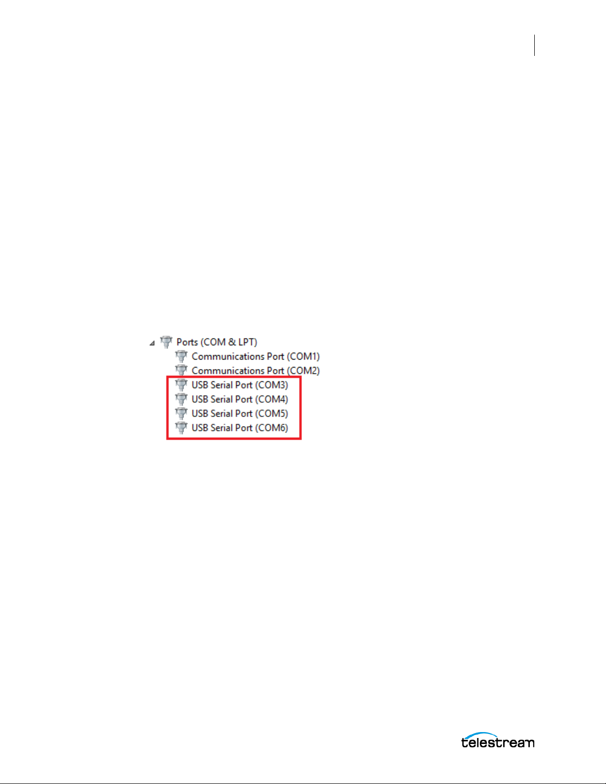
Configuring and Updating Live Capture
Creating a Live Capture Workflow
Troubleshooting the VTR Connection
If you have an active Capture workflow that is configured as described above, but its
Monitor Status returns "Initializing: VTR not connected", you can perform some of the
following troubleshooting steps:
1. Make sure that the RS-422 interface box is correctly installed, all adapters and
cables are properly connected, and the VTR is powered up. See Appendix B:
Installing the RS-422 Interface Kit for complete instructions.
2. Check that the Source input of the Capture action matches the RS-422 port that the
VTR is connected to. For example, when using SDI Input 1 for the Lightspeed Live
server in the Capture action you must connect to Channel 1 (CH1) on the RS-422
interface box. See Connecting a VTR to the Lightspeed Live Server in Appendix B
for a diagram and details.
3. Check that the RS-422 interface box’s Serial Ports are shown in the server Device
Manager. Open the Device Manager and toggle open the “Ports (COM & LPT)”
devices. When properly connected, the ports of the RS-422 interface box will
appear as USB Serial Port (COM3) through USB Serial Port (COM6) as shown in the
following image.
61
4. Check the Properties for each USB Serial Port to verify that its Port Settings are set
5. In Advanced... confirm that Latency Timer (msec) is set to 1.
6. If the VTR is not connecting after performing steps 1 through 5, you can try
After performing each step above, you can check the Workflow's Monitor Status panel
to see if the Status has changed to "Initializing: VTR connected", as shown in the image
on the previous page.
When the VTR connection is successfully initialized, use the Live Capture web
application to set recording parameters and control the VTR to ingest media from tape.
See VTR Mode Controls and Indicators for instructions.
Lightspeed Live Guide
correctly to:
Bits per Second — 9600
Data Bits — 8
Parity — None
Stop Bits — 1
Flow Control — None
replacing the system cables.
Page 62

62
Configuring and Updating Live Capture
Live Capture Server Configuration Changes
Live Capture Server Configuration Changes
The following topics explain how to make common configuration changes.
■ Renaming a Lightspeed Live Capture Server
■ Joining Multiple Capture Servers
■ Uniquely Named Multiple Capture Servers
■ Best Practice for Multiple Live Capture Server System Design
■ Connecting the Applications for Multiple Servers
Renaming a Lightspeed Live Capture Server
Each Lightspeed Live system domain uses the name assigned to the Windows server
that hosts the Vantage domain database as its domain name. When you first receive
your Lightspeed Live server, it has Vantage core code pre-installed with a Vantage
domain database on the server. The domain database uses the machine's name.
If you want to rename your Lightspeed Live server and keep the pre-installed Vantage
database, you’ll complete the following tasks to ensure that your database is updated
with the new machine name (detailed steps following):
• Remove all Vantage services from the Vantage domain.
• Rename the Windows server that hosts the Vantage domain database.
• Restart the renamed server and add all Vantage services to the renamed domain.
CAUTION: The server name must be limited to 15 characters or less.
Note: To complete this procedure, your Windows user must have permission to
rename the computer, or you must get assistance from your Windows domain
administrator. Be sure to schedule the rename during a maintenance window, as
renaming the Vantage domain interrupts all Vantage services in the domain and all
Windows services on the server are renamed.
Use the following steps to rename a Vantage server and domain.
1. Start the Vantage Management Console, select the domain to manage, and log on
as described in Starting the Vantage Management Console in the Vantage Domain
Management Guide.
2. Select Services in the component panel.
3. Take note of Storage, Variables, and/or Qualification Rules settings for each service
that you have configured.
Write down any Storage, Variable, and/or Qualification Rule settings that you
want to reconfigure after the Vantage domain is renamed.
Lightspeed Live Guide
Page 63

Configuring and Updating Live Capture
Live Capture Server Configuration Changes
Note: When you remove Vantage services from the domain, the Storage, Variable,
and Qualification rule configuration for each service is lost. The rest of the Vantage
domain configuration is retained. If you are changing the machine name during initial
server installation, no custom rules have been configured, so this does not apply.
4. Click a service in the Services details panel, then press Ctrl-A to select all services.
5. Click the Remove Service button in the toolbar.
6. Click Start > Administrative Tools > Server Manager.
7. Click Server Manager in the left pane.
8. Click Change System Properties in the right pane.
9. Select the Computer Name tab and click Change.
10. Enter the new computer name in the Computer Name text field and click OK. This
new computer name becomes your new Vantage domain name.
11. If prompted to do so, enter a Windows user name and password for an account that
has permission to rename this computer in the Windows domain.
63
12. Restart the server.
Note: If you are not able to log in with the local Administrator account, check the
hostname listed by Windows as it may not have been updated. For example, if the
original hostname was lsl-telestream and the new one is lsl-customer, the User Name
may still be listed as: lsl-telestream\Administator. If so, change the hostname to:
lsl-customer\Administrator, and re-enter your password.
13. Start the Vantage Management Console, select the new domain to manage, and
log on.
– If you are not prompted to select the new domain, click on File > Change
Vantage Domain, click Search, select the new domain and click OK.
14. Select Services in the Component panel.
15. Click the Add Service button in the toolbar.
16. When the Select Service dialog appears, click Machine to sort the services by
machine name.
17. To add Vantage services for a specific machine, select the services you want and
click OK.
18. If any Storage, Variables, and/or Qualification Rules settings were configured for
services, add them now.
19. Send the new Vantage domain name to all Vantage users and administrators so
they can reconnect to the Vantage domain.
This completes the renaming procedure.
Lightspeed Live Guide
Page 64
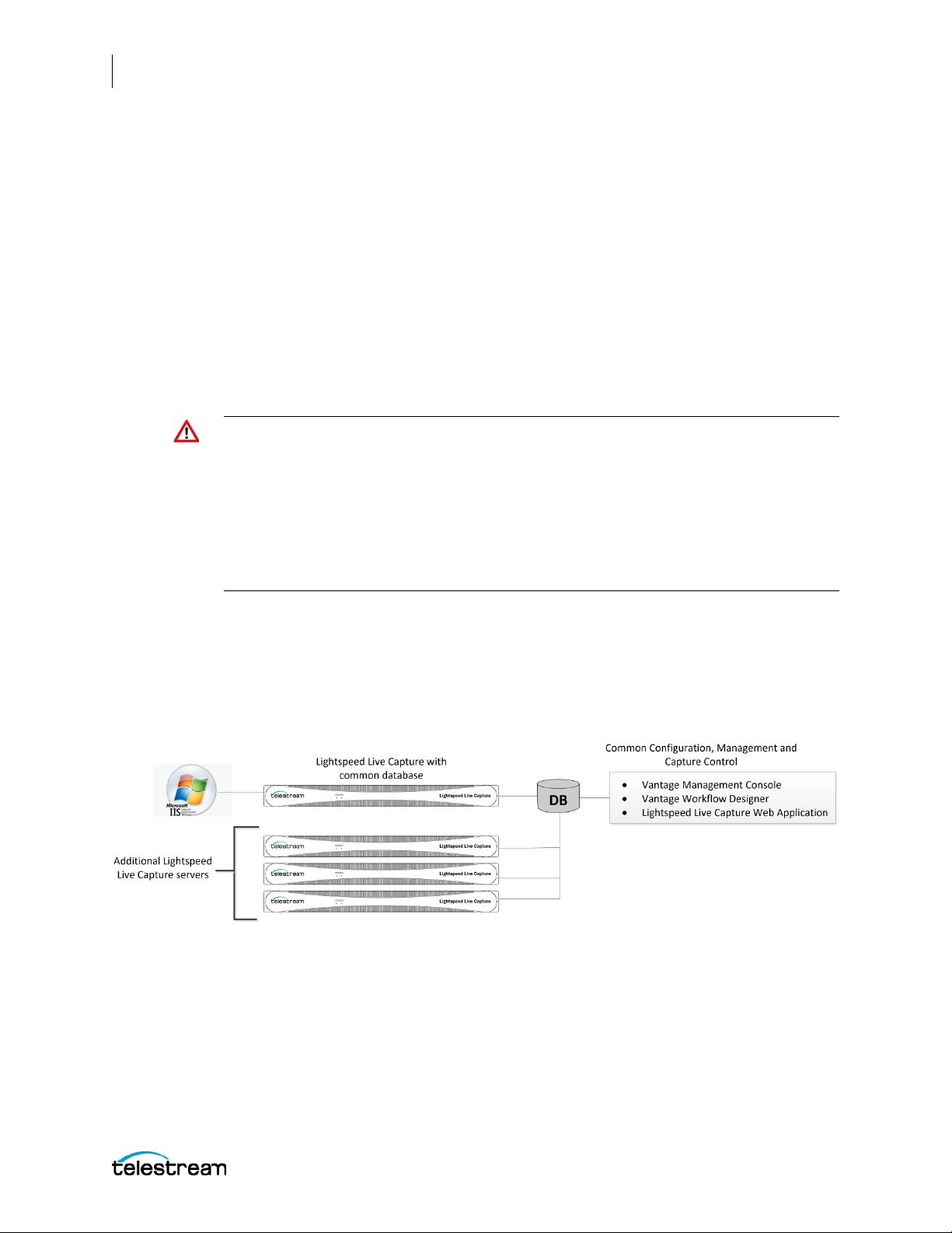
64
Configuring and Updating Live Capture
Live Capture Server Configuration Changes
Joining Multiple Capture Servers
Your Lightspeed Live Capture server is factory-configured as a standalone live Capture
system. This configuration includes a Vantage database running on each individual
standalone Live Capture server. If you wish to manage multiple Live Capture servers
from a common interface, or add Live Capture servers to an existing Vantage Array, you
can do this in two ways:
• For Capture-only systems, join all Live Capture servers together by creating a sys-
tem that utilizes a single domain database.
• For Capture systems that will be utilizing other Vantage services and actions, such
as Transcoding and Analysis, you can add your Live Capture servers to an existing
Vantage Array system.
Important Note: When standalone Lightspeed Live Capture servers are combined
together using a single database, only those ComponentPacs properly installed on the
master Domain Database will be utilized. When joining Lightspeed Live Capture
servers together into a Live Capture-only system, or into an existing Vantage Array,
always verify that all of the required ComponentPacs are properly installed on the
combined system's master Domain Database. For details on how to install
ComponentPacs see Updating Your Server using Secured Version Control and
ComponentPacs below.
Capture-Only Systems
Two or more Lightspeed Live Capture servers can be joined together to form a multiple
server Live Capture-only system. This allows for common configuration, management,
and capture control.
To join Lightspeed Live Capture servers together, follow these steps:
1. Select one of your Lightspeed Live Capture servers to act as the master domain.
The master domain server system will contain the common database and will have
all the services running on other Lightspeed Live Capture servers added to it via the
Vantage Management Console.
2. Add all services running on your Lightspeed Live Capture servers to the Lightspeed
Live Capture master domain server. See the Vantage Domain Management Guide for
details on adding services.
Lightspeed Live Guide
Page 65

Configuring and Updating Live Capture
Live Capture Server Configuration Changes
65
3. Apply the appropriate multiple-server Vantage license onto the system running the
master domain database. See the Vantage Domain Management Guide for details
on licensing.
To configure, manage, and control your Lightspeed Live Capture system, run the
Vantage Management Console, Vantage Workflow Designer, and Lightspeed Live
Capture web applications pointing to the domain contained on the Lightspeed Live
Capture master domain server selected in Step 1, above.
Important Note: Live Capture-only configurations do not require Vantage Array
licensing. When Live Capture workflows are created and executed, all processes will
run on their respective Live Capture servers automatically.
Existing Vantage Array - Adding Live Capture Server(s)
Joining Lightspeed Live Capture systems to an existing Vantage Array allows Vantage
workflows to begin with a Capture origin action that is connected to other Vantage
actions and services, such as general transcoding, IPTV/VOD transcoding, analysis, third
party application control, delivery options, or other service/action types.
Lightspeed Live Guide
Page 66

66
Configuring and Updating Live Capture
Live Capture Server Configuration Changes
Adding Services
The Lightspeed Live Capture server includes Vantage services, so adding these services
to an existing Vantage Array is no different than adding any other Vantage service
running on a separate server to a Vantage Array.
Important Note: Joining Live Capture services to an existing Vantage Array requires
the appropriate Vantage Array licensing. See the Vantage Domain Management
Guide for details.
To add Lightspeed Live Capture services to a Vantage Array, follow these steps:
1. Verify that the Lightspeed Live Capture services are running, all Vantage Services
are running on the server, and no jobs are being processed in the local, factoryinstalled All-In-One domain.
2. Verify that you have configured the other (non-Lightspeed) Vantage domain server
with Array, and it is active. Refer to the Vantage Domain Management Guide >
Installing a Vantage Distributed Domain, for more details.
3. Verify that the Lightspeed Live Capture server is on the same network as the
existing Vantage Array domain, with sufficient network permissions and access.
Refer to the Vantage Domain Management Guide > Network Requirements, to
configure your network.
4. Start the Vantage Management Console, and select the new Vantage Array domain.
5. Add the services on the Lightspeed Live Capture server to the new Vantage Array
domain, just as you would do with any Vantage Services running on any Vantage
server.
6. Apply the appropriate multiple-server Vantage license onto the system running the
master domain database. See the Vantage Domain Management Guide for details
on licensing.
Uniquely Named Multiple Capture Servers
To ensure each capture source has a unique name when multiple Live Capture servers
are part of a multi-server Capture-only system, or part of an existing Vantage array, the
Live Capture server name is included automatically by default in each source name.
Sources will be automatically named as follows:
[Live Capture server name] - SDI Input [1 thru 4]
For example, when a Live Capture server has the server name of LiveCapture1 the
source inputs are automatically named, by default:
LiveCapture1 - SDI Input 1, LiveCapture1 - SDI Input 2, LiveCapture1 - SDI Input 3,
and LiveCapture1 - SDI Input 4
If you change the default source names by using the Vantage Management Console's
Capture Inventory window, keep in mind that all sources in an array need to be
uniquely named so you can easily distinguish sources on one server from another.
Lightspeed Live Guide
Page 67
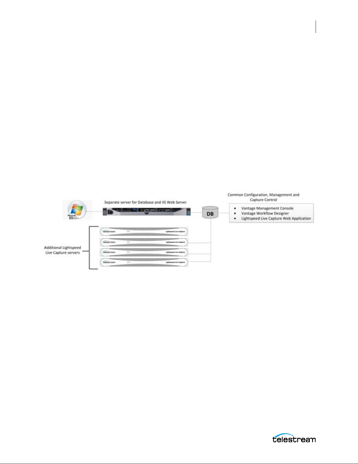
Configuring and Updating Live Capture
Live Capture Server Configuration Changes
Best Practice for Multiple Live Capture Server System Design
Best practice for multiple Live Capture server systems is to install and run the "Vantage
master domain" database and IIS Web Server on a server(s) that is separate from the
Live Capture servers. See the Vantage Domain Management Guide for details on how to
install a Vantage Database and Microsoft's IIS Web Server.
When clustering multiple Live Capture and Vantage servers together, it is best to use a
separate server designated as the IIS Web host to serve up the Live Capture Web
application. Ideally the web host would be separate from the "Vantage master domain"
database system since both IIS and SQL can consume a considerable amount of system
resources.
The following are two example systems utilizing a separate Database and IIS Web
server.
Capture-only System
67
For this Capture-only system example, the "Vantage master domain" database and IIS
Web server are installed together on a separate server. This prevents database or Web
server resources consumption from affecting the Live Capture servers.
Lightspeed Live Guide
Page 68
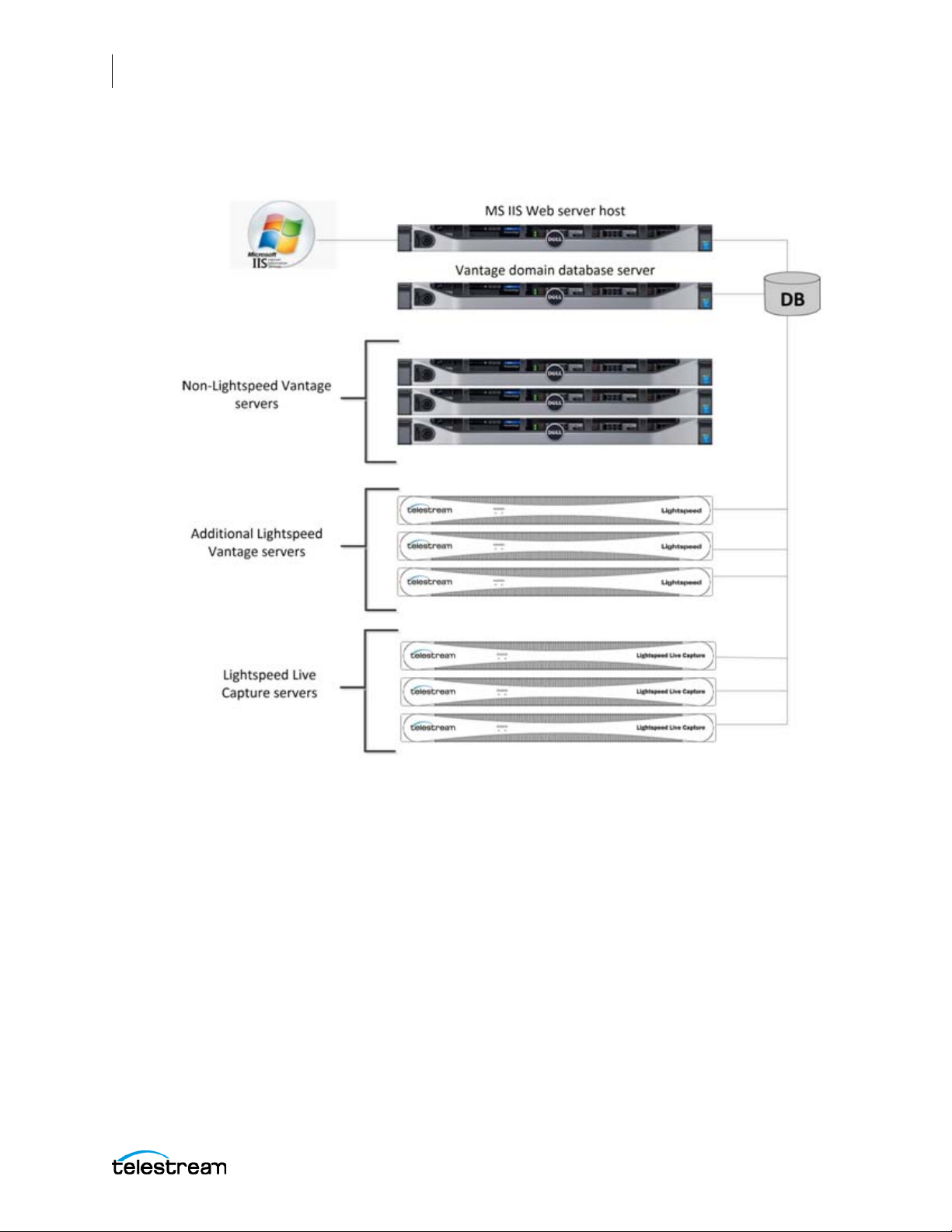
68
Configuring and Updating Live Capture
Live Capture Server Configuration Changes
Live Capture/Vantage Array—with Separate Vantage Domain Database
and IIS Web Host Servers
For this example the "Vantage master domain" database and IIS Web server are
installed on two completely separate servers. Since this is a large system array
containing six (6) Vantage system and three (3) Live Capture servers, separating the
database and Web Server is recommended to prevent the database and IIS Web server
resource consumption from affecting the Live Capture and Vantage servers.
Lightspeed Live Guide
Page 69

Configuring and Updating Live Capture
Live Capture Server Configuration Changes
Connecting the Applications for Multiple Servers
When there are multiple Capture server systems where the database and web server
reside on specific server(s) within the multiple server configuration, the Vantage client
applications and /or the Live Capture web app need to be configured to connect to the
appropriate server.
Configuring Vantage Client Applications for Multiple Servers
Since the database in a multiple server system is located on a separate server, the
Vantage client applications must "point to" that database. This is done by selecting the
database server from the Select Vantage Domain dialog in the Vantage client
applications.
69
Using the Vantage Desktop Client Applications
First, install the Vantage Management Console and Vantage Workflow Designer client
applications on any Windows system on your network. To use these client applications,
you must change the Vantage Domain so they connect to the server that is running the
Vantage master domain database.
Select Change Vantage Domains from the File menu of each client application to open
the Select Vantage Domain dialog.
Note: To learn more about the Vantage Management Console or Vantage Workflow
Designer, click the ? icon or use the Help menu to open the searchable Vantage User
Guide. The ? opens to the topic that matches the area of the user interface that you are
using.
Lightspeed Live Guide
Page 70

70
Configuring and Updating Live Capture
Live Capture Server Configuration Changes
Using the Live Capture Web App with Multiple Servers
To use the Lightspeed Live Capture web application when there are multiple servers,
first install the Vantage Web Applications on the server running the IIS Web service. To
open the Lightspeed Live Capture web application, use the following URL:
http://[Name or IP Address of server running IIS Web service]/Vantage/
CapturePortal/Default.aspx
When asked to select a Vantage Domain, choose the server hosting the Vantage master
domain database.
Lightspeed Live Guide
Page 71
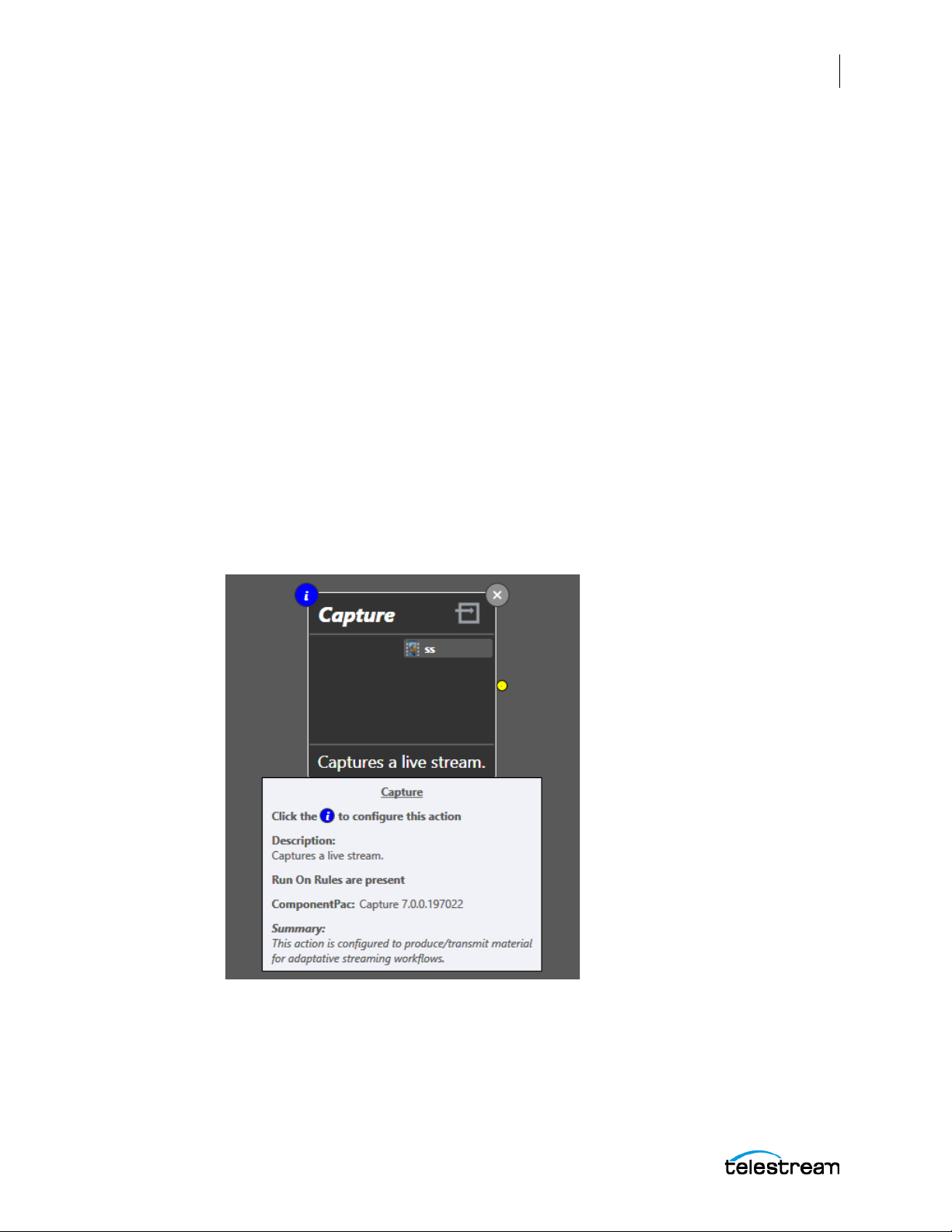
Configuring and Updating Live Capture
Updating Your Server using Secured Version Control and ComponentPacs
Updating Your Server using Secured Version
Control and ComponentPacs
ComponentPac update packages are part of Telestream's Secure Version Control
feature. For details, see the Secured Version Control application note on the Telestream
web site.
Secured Version Control provides the ability to install the latest software—and begin
building Workflows that utilize new ComponentPac libraries (software libraries), while
keeping the existing Workflows untouched and operating from previous versions of a
ComponentPac. When, and if, it is desired to upgrade a Workflow or Action within a
Workflow, it can be done at a convenient time. Secured Version Control has been
implemented as part of Lightspeed Live Capture and Vantage v7.0. ComponentPacs are
architected in such a way as to facilitate the inclusion of multiple component versions.
With Secured Version Control, it is quite easy to manage the ComponentPac versions
within Workflows. ComponentPacs are software libraries that do the "heavy lifting" of
managing the Actions, such as Capture. When you hover over the "i" icon at the top left
corner of an action, information is displayed which includes the version of the
ComponentPac library. In the following image, the Capture action's ComponentPac is
shown as "Capture 7.0.0.197022".
71
For more information see the Secured Version Control application note on the
Telestream web site.
Lightspeed Live Guide
Page 72
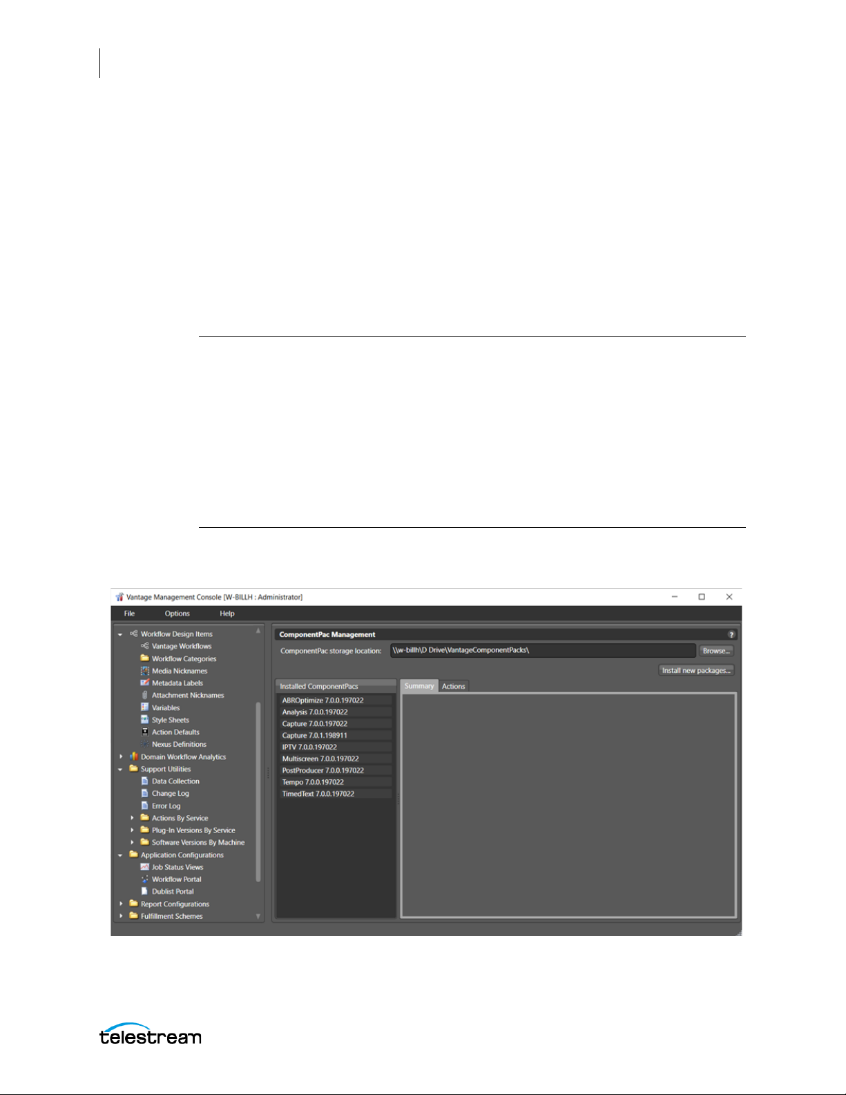
72
Configuring and Updating Live Capture
Updating Your Server using Secured Version Control and ComponentPacs
Installing a ComponentPac Update
Follow these steps to install a ComponentPac:
1. On a multiple server system utilizing a single database, verify that all Vantage
services have been assigned to the desired domain database.
2. Download the ComponentPac update file(s) from the Lightspeed Live Capture
download page at www.telestream.net.
3. Place the Capture ComponentPac file, and any other applicable ComponentPac(s)
file(s), into a network folder that is reachable by all Vantage and Lightspeed Live
Capture servers in your domain.
Important Note: The Vantage services must have permission to access the network
location where the ComponentPac is placed. User credentials can be provided to
Vantages services in one of two ways:
a. Change the log on of the Vantage services via the Windows Services console.
b. Use the Authorization tab within Settings & Options of the Vantag e
Management Console to specify authorization credentials for remote
folder access.
After applying credentials to Vantage services, the services must be restarted in order
to complete the change.
4. Open the Vantage Management Console and select ComponentPac Management
from the menu.
Lightspeed Live Guide
Page 73
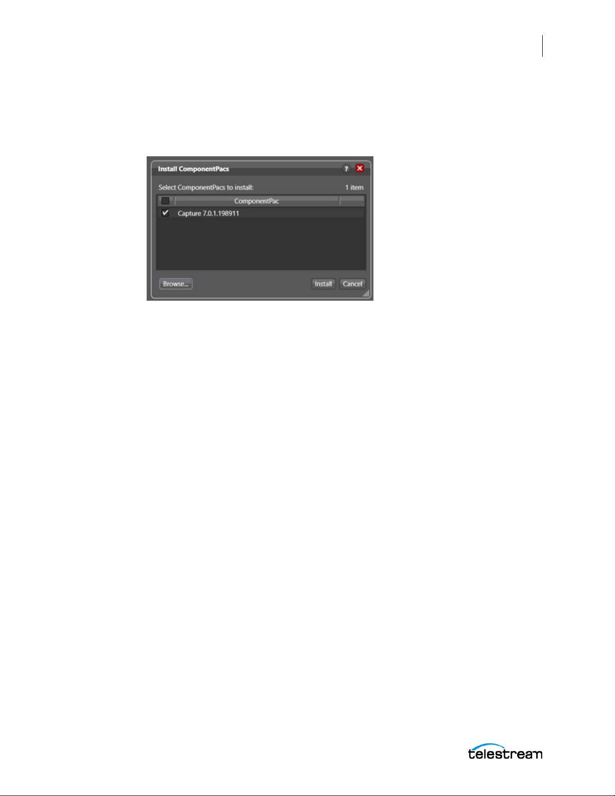
Configuring and Updating Live Capture
Updating Your Server using Secured Version Control and ComponentPacs
5. In the ComponentPac Management panel click Browse to find the network location
where your ComponentPac update files reside, then click Install new packages…
6. Confirm that all of the ComponentPacs you wish to install are listed and enabled in
the Install ComponentPacs dialog.
7. Click Install. The ComponentPacs selected will be installed and displayed in the
ComponentPac Management's Installed ComponentPacs window.
8. In order for the installed ComponentPacs to be available for use, services hosting
the affected actions will need to be restarted.
73
Updating Workflows and Actions for ComponentPacs
To update an existing action or workflow to utilize a newly installed ComponentPac,
use the Vantage Workflow Designer to right-click and select Upgrade to upgrade the
action or workflow as a whole. Select a specific action to right-click and upgrade, or
upgrade the entire workflow by right-clicking in the workflow window and selecting
Upgrade. Newly created actions will always use the latest ComponentPac installed.
For information on how to update Workflows and Actions utilizing new Vantage
features without compromising existing Vantage workflows see the Secured Version
Control application note on the Telestream web site.
Lightspeed Live Guide
Page 74
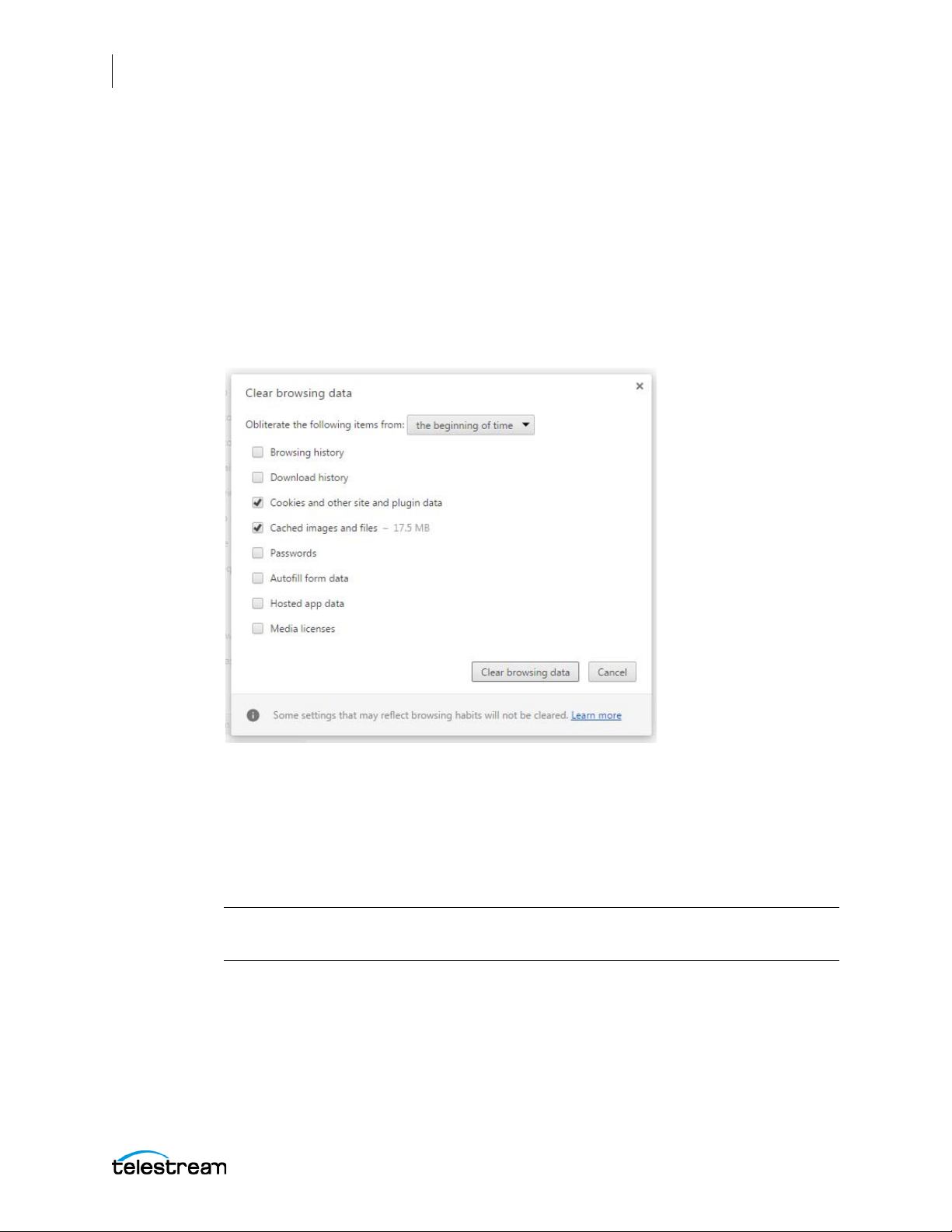
74
Configuring and Updating Live Capture
Clear Browsing Data after Updating Vantage or Live Capture
Clear Browsing Data after Updating Vantage or
Live Capture
After a Vantage or ComponentPac update is installed, you must clear the browsing data
in your Chrome browser in order for the Lightspeed Live Capture web application to
operate properly.
Follow these steps to clear the browsing data:
1. In Google Chrome click the “Customize and Control” icon, select the “More Tools”
menu and choose “Clear browsing data...”. The Clear browsing data options appear.
2. In the Clear browsing data options select “The beginning of time” from the dropdown menu, then place a check-mark in “Cookies and other site and plugin data”,
and “Cached images and files”.
3. Click the “Clear browsing data” button.
Your browser should now be ready to operate properly with the new update.
Note: The Live Capture Web Application, ComponentPac version 7.0.2, will not
function unless the Vantage 7.0 Update Pack 1 (UP1) Web Apps are also installed.
Lightspeed Live Guide
Page 75

The Lightspeed Live Capture Web Application
This chapter describes the Lightspeed Live Capture web application, how to install it,
access it, and how to use it.
This chapter covers the following topics:
■ Lightspeed Live Capture Web App Overview
■ Installing the Lightspeed Live Capture Web App
■ Accessing the Lightspeed Live Capture Web App
75
■ Using the Lightspeed Live Capture Web App
■ Using the Job Status Views
Note: Only the Chrome browser (version 50 or greater) is supported for the
Lightspeed Live Capture web application.
Page 76
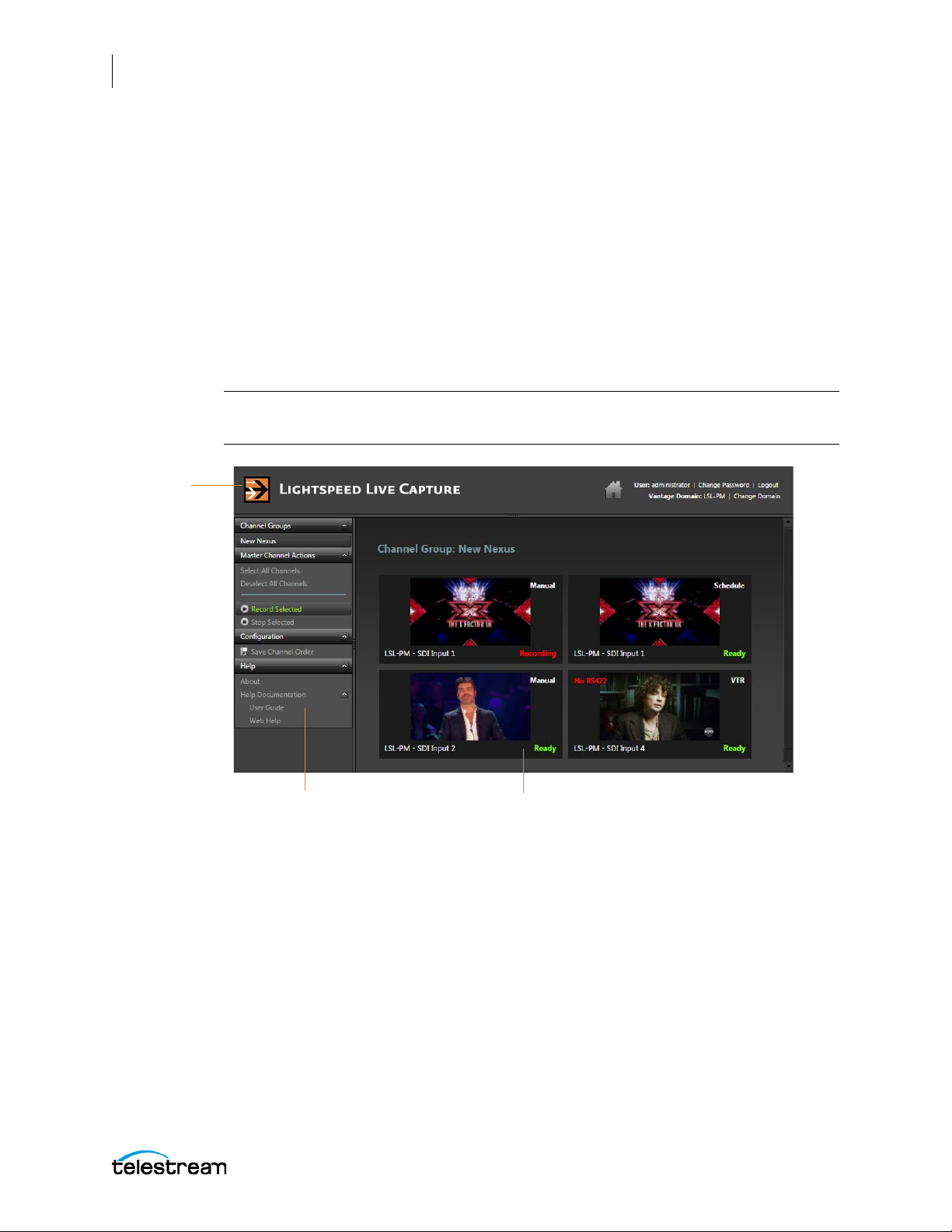
76
Menu panel
Channel View panel
Title panel
The Lightspeed Live Capture Web Application
Lightspeed Live Capture Web App Overview
Lightspeed Live Capture Web App Overview
Lightspeed Live Capture is a web application, where you can:
• Select Live Capture channels and channel groups
• View information about each capture channel
• View images of the content of each channel
• Control the operation of each channel
• Turn recording of the selected capture channels on or off
• Access information about using Lightspeed Live Capture
Note: A user must have the appropriate permissions to gain full access to all of the
controls and features of the Lightspeed Live Capture web application.
The Lightspeed Live Capture web application is presented in three panels:
• Title panel—Displays the home button, Vantage domain and user name, and con-
trols to manage the user password, change domains, and to log out or log in.
• Menu panel—Provides a list of the available Channel Groups, actions to take on
channels, and links to documentation.
• Channel View panel—Displays views of channel content, status messages, and pro-
vides access to controls for each channel.
Lightspeed Live Guide
Page 77

The Lightspeed Live Capture Web Application
Installing the Lightspeed Live Capture Web App
Installing the Lightspeed Live Capture Web App
Lightspeed Live Capture is a web application that comes pre-installed on Lightspeed
Live Capture servers. The application is facilitated by IIS (Windows Internet Information
Services) which ships properly configured in the Lightspeed Live Capture server.
Installation on Standard Servers
For standard servers (other than Lightspeed Live Capture) you must set up IIS first. If IIS
is already installed, you must create the configuration that supports Vantage Web
Applications.
For full details about setup for standard servers, see “Installing and Configuring Vantage
Web Applications” in the Vantage Installation Guide or the Domain Management Guide.
An easy way to get to the Domain Management Guide is to open the Vantage
Management Console and click the ? in the upper right corner.
See Configuring Settings for Your Facility for information about the Vantage
Management Console.
77
The following are additional helpful topics to search for in the Vantage Installation
Guide or the Domain Management Guide:
• “Server Hardware Requirements”
• “Vantage Web Applications OS”
Clear Browsing Data after Updating
After a Vantage or Live Capture ComponentPac update is installed, you must clear the
browsing data in your Chrome browser in order for the Lightspeed Live Capture web
application to operate properly. See Clear Browsing Data after Updating Vantage or
Live Capture for detailed information.
Lightspeed Live Guide
Page 78
78
The Lightspeed Live Capture Web Application
Accessing the Lightspeed Live Capture Web App
Accessing the Lightspeed Live Capture Web App
Only the Chrome browser (version 50 or greater) is supported to work with the
Lightspeed Live Capture web application. You can directly access the locally installed
Lightspeed Live Capture web application using this URL:
http://localhost/Vantage/CapturePortal/Default.aspx
If you are accessing the Lightspeed Live Capture web app remotely, replace “localhost”
with the DNS server name or IP address:
http://<ServerName>/Vantage/CapturePortal/Default.aspx
When asked to for the Lightspeed Live Capture Login, enter the Vantage user name and
password assigned to you during Vantage configuration as described in the Configuring
and Updating Live Capture chapter of this guide.
You can also access the Lightspeed Live Capture web application from the Vantage
Web Applications Menu as explained below.
Changing the Domain
If you have changed your server's hostname, when accessing the Lightspeed Live
Capture web application you should verify that it is using the new domain. You can see
the current domain name after Vantage Domain: in the right of the Title panel.
If not using the correct domain, you can change the domain by clicking on Change
Domain in the Title panel. Click OK to log out, then click Search in the dialog that
appears, select the correct domain, and click OK. Enter the user name and password to
log into the selected domain.
Lightspeed Live Guide
Page 79
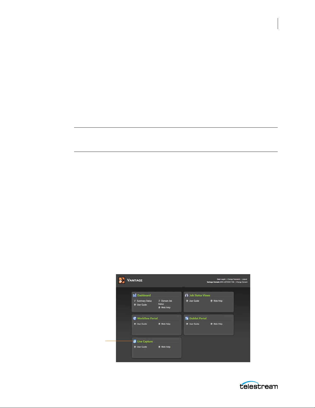
Launching the Web Applications Menu
Open the
Live Capture
application
To launch the Vantage Web Applications Menu home page, do the following:
1. Open your Chrome browser and enter the Vantage Web Applications Menu home
page URL:
http://<IISServerName>/Vantage/
where <IISServerName> is the DNS name of the IIS server (or its IP address)—by
default, the same as the Vantage domain server.
If you are using Web applications directly on the server hosting IIS, you can use
localhost as the server name: http://localhost/Vantage/.
Note: If you do not know the name of the Vantage IIS server (by default, the same
server where the Vantage domain database is hosted), contact your Vantage
administrator or IT department.
2. If you are prompted to select a domain, select the domain where your capture
services are running, and click OK.
The prompt appears the first time you connect to a Vantage domain from this computer (or you deleted your browser’s cookies). Select the domain from the list and
click OK to continue.
The Lightspeed Live Capture Web Application
Accessing the Lightspeed Live Capture Web App
79
3. Enter an authorized user name and password.
Vantage displays the Vantage Web Applications Menu home page.
For more details on using and configuring Vantage Web applications see the Vant age
User’s Guide. This guide is available from the User Guide link in the Vantage Web
Applications Menu.
Opening the Live Capture Application
To open the Live Capture web application click the Live Capture link in the Vantage
Web Applications Menu home page, as shown below.
Lightspeed Live Guide
Page 80
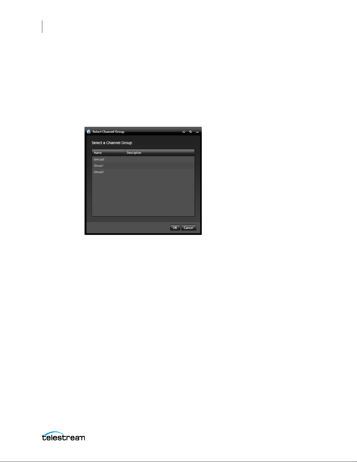
80
The Lightspeed Live Capture Web Application
Accessing the Lightspeed Live Capture Web App
Selecting a Channel Group
A Channel Group is a collection of workflows that are associated with each other to
create a common point of interaction. For example, one group could be several camera
video feeds from the same studio, and another group might come from a different
studio. The Channel Group that a workflow is assigned to is selected in the Capture
action. See Program Input in Appendix A for more information.
When you click the Live Capture link, the Select Channel Group dialog opens, if you
have not selected a Channel Group before.
Channel Group List
The list of Channel Groups which appear in the Select Channel Group dialog are
dependent upon the access permissions of the user that is logged into the Vantage
Web Applications. Select the Channel Group you want to use and click OK. The
Lightspeed Live Capture web application opens in your browser.
Creating a New Channel Group
Channel Groups are created, and their properties are edited, in the Vantage
Management Console. See Configuring a Channel Group Nexus for instructions on
creating a new Channel Group.
Lightspeed Live Guide
Page 81
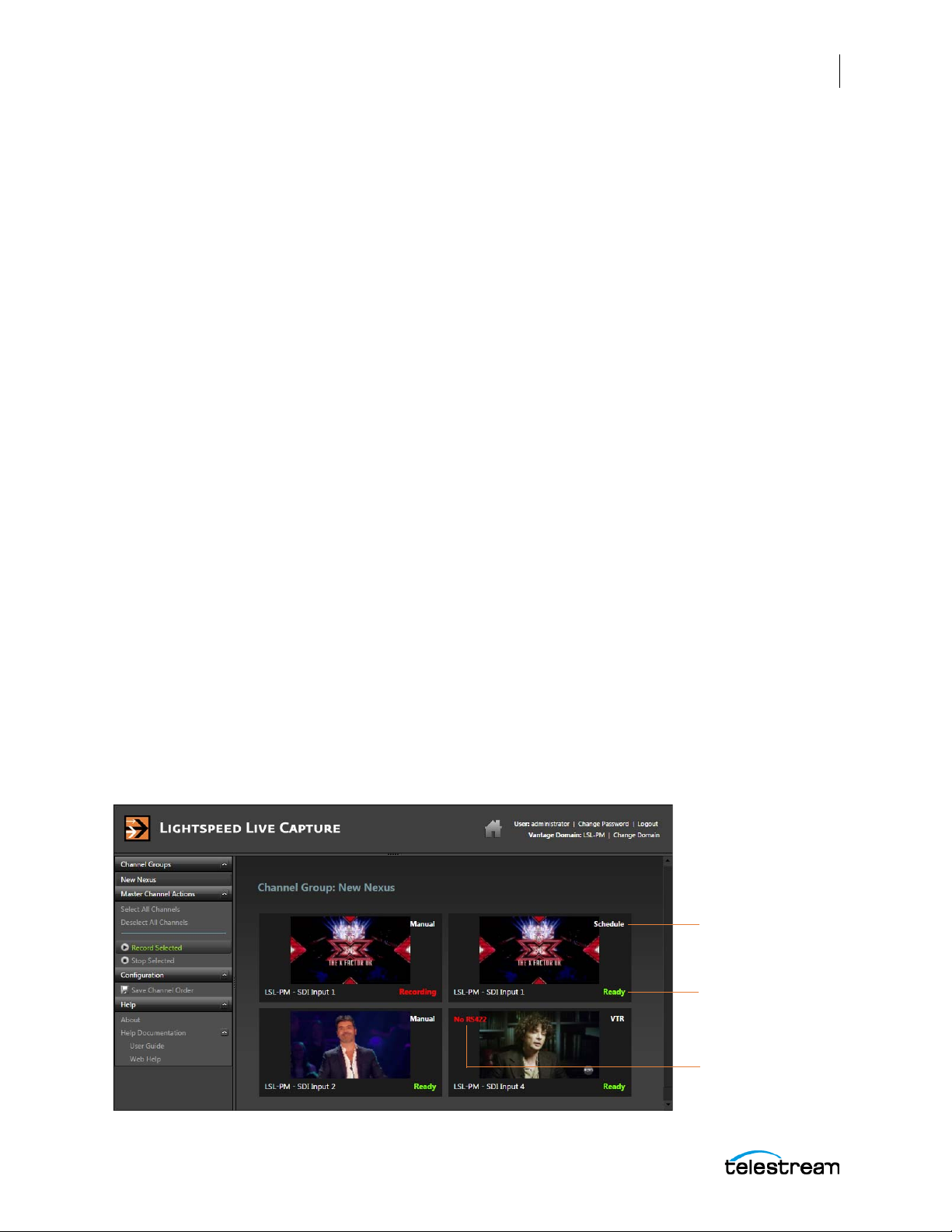
The Lightspeed Live Capture Web Application
Trigger Mode
Status
RS-422 Status when
in VTR Mode
Using the Lightspeed Live Capture Web App
Using the Lightspeed Live Capture Web App
With the Lightspeed Live Capture web application you can view and control the
operation of the capture channels, as well as turning recording on or off for selected
channels.
Set Capture Action to Manual or VTR for Channel Control
The Lightspeed Live Capture web application allows control over capture channels that
are configured within a workflow for Manual or VTR start trigger. Channels not
configured for Manual or VTR start are presented in the Lightspeed Live Capture web
app as read-only status views. A channel in read-only status cannot be controlled from
the Lightspeed Live Capture web app.
The Manual and VTR start settings are selected in the Trigger section of the Capture
action. See Trigger Settings in Appendix A for information on these settings.
Channel View Panel
The Channel View panel displays the video content of the workflow channels in the
selected Channel Group, updating each image once per second. The Trigger mode set
for each channel of Manual, VTR, Schedule, or Web Service, is displayed in the upperright corner. Status indicators show the current state of each channel, such as Ready,
Recording, or Paused. When a channel is in VTR Trigger mode, the RS-422 status is
displayed in the upper left corner.
81
The first user that accesses a Channel Group is considered the primary user. Once a
primary user is designated, only that user can invoke and use the live interactive
features of the channel controls. All other users see a ‘status’ view of the channels and
channel control.
Right-click on a channel to select it. You can right-click additional channels, so that
multiple channels can be selected. When a channel is selected, right-click on it to
deselect it. There is no limit to the number of channels that can be displayed, however,
the recommended maximum number is 20.
Lightspeed Live Guide
Page 82
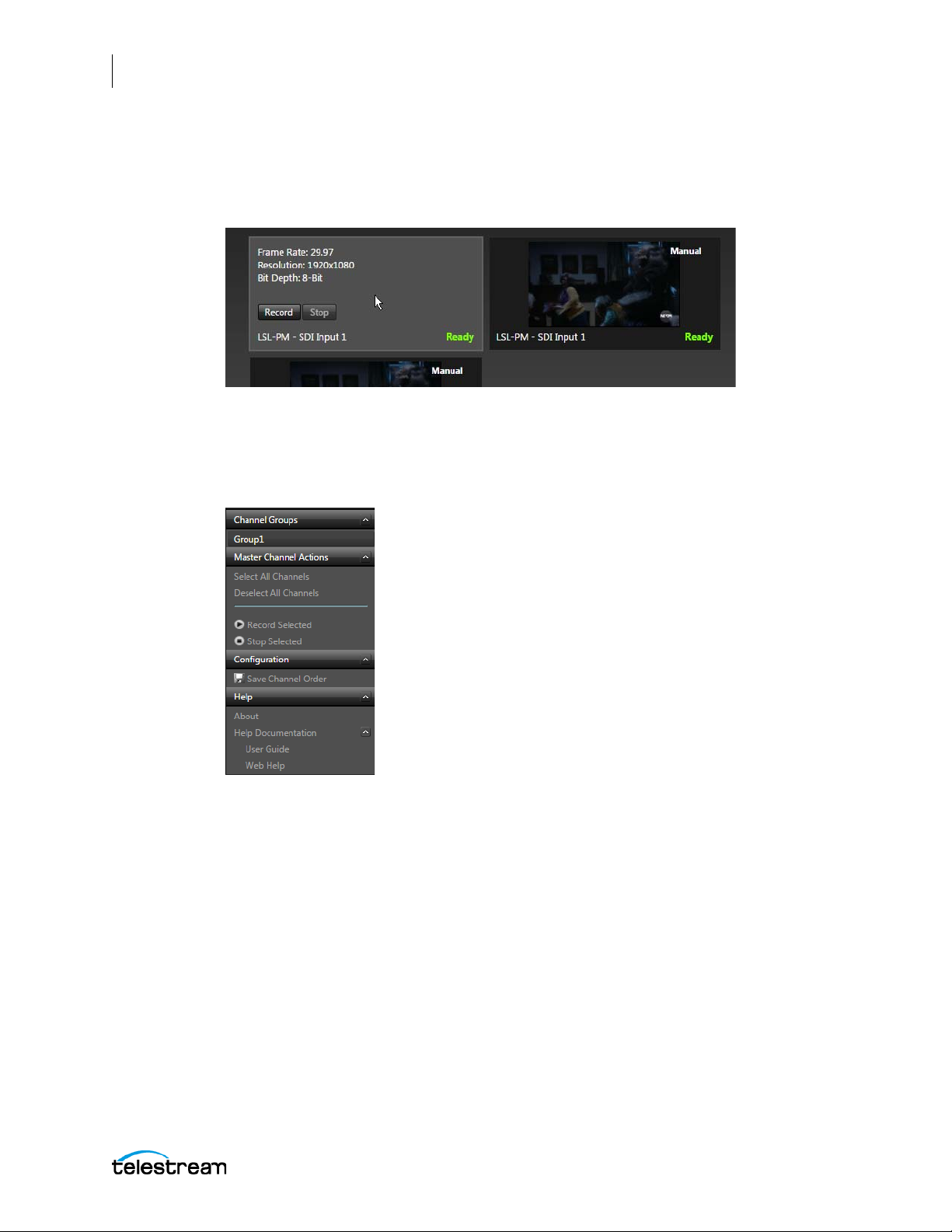
82
The Lightspeed Live Capture Web Application
Using the Lightspeed Live Capture Web App
Basic Information and Control Display
Hover over a channel to see basic information about that channel, and to access the
Record and Stop buttons for that channel:
Lightspeed Live Capture Menu Panel
The following describes the options available in the Lightspeed Live Capture web app
menu panel.
Channel Groups
The Channel Groups menu displays the Channel Groups that are currently available.
Select the Channel Group you want to view and control.
Master Channel Actions
These options are available in the Master Channel Actions menu:
• Select All Channels—Select all channels displayed in the Channel View panel.
• Deselect All Channels—Deselect all channels displayed in the Channel View
panel.
• Record Selected—Record the currently selected channel(s). Record Selected oper-
ates in two different modes depending on whether Time-Shift has been enabled in
Lightspeed Live Guide
Page 83

The Lightspeed Live Capture Web Application
Using the Lightspeed Live Capture Web App
the workflow. See Program Input in Appendix A for information about enabling and
setting Time-Shift.
– When Time-Shift is NOT enabled in the workflow, all channels start recording
immediately with no attempt to synchronize the start timecode.
– When Time-Shift has been enabled in the workflow, the system attempts to
synchronize all of the selected channels to the exact same start timecode before
starting the recording. When recording starts, some portion of the frames in the
Time-Shift buffer are added to the start of the recorded file (going back in time to
included frames from the past).
All selected channels must have the same timecode source in order to be
synchronized to the exact same frame during the recording operation.
• Stop Selected
– When Time-Shift is NOT enabled, stops recording the selected channels at the
current time.
– When Time-Shift has been enabled, stops recording the selected channels at the
current time, plus the frames contained in the Time-Shift buffer.
83
Configuration
• Save Channel Order—The order of the displayed channels is saved when Save
Channel Order is selected. When the Live Capture web application is closed and reopened the saved display order is recalled.
Help
The Help options provide information about using Lightspeed Live Capture:
• About—Displays the version number of Lightspeed Live Capture.
• User Guide—Opens the PDF version of the Lightspeed Live Guide (this document)
in a new browser page.
• Web Help—Opens the web help version of the Lightspeed Live Guide.
Lightspeed Live Guide
Page 84
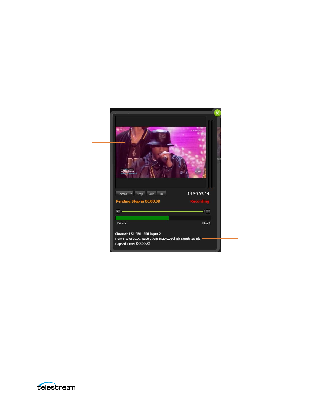
84
Video View Panel
Close the Dialog
Operation Controls
Source Name and Input ID
Timecode
Audio Level Meters
Video Information
Timeline Slider /
Frame Step
Seconds in the
Time-Shift Buffer
Status Bar
Present Capture
State
Elapsed Time of Current
Recording
Pending Capture State
The Lightspeed Live Capture Web Application
Using the Lightspeed Live Capture Web App
Manual Mode Controls and Indicators
When the Capture action Trigger option is set to Manual mode the Channel Control
dialog provides display of the video source, information about the selected channel,
and provides controls for the operation of the channel. The Primary and Secondary
Outputs are both affected by the controls at the same time. See Capture Action in
Appendix A for more information on setting the Trigger option.
Click on a channel to open its Channel Control dialog.
Controls for Manual Mode
The following controls are provided in the Channel Control dialog when the Trigger
mode is set to Manual in the Capture action:
Note: For the Timeline Slider, Status Bar, and Time-Shift buffer to be available and
active, the Time-Shift option must be checked in the Program panel of the Capture
action. See Program Input in Appendix A for more information.
Lightspeed Live Guide
Page 85
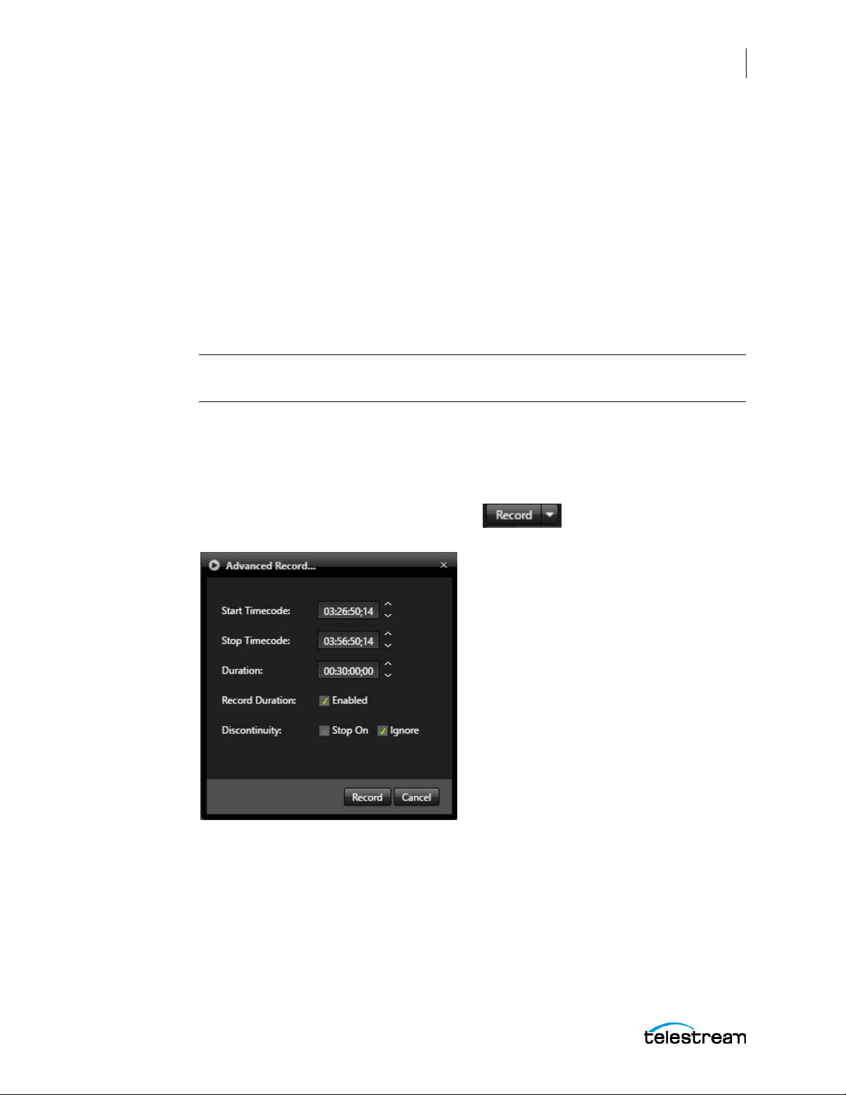
The Lightspeed Live Capture Web Application
Using the Lightspeed Live Capture Web App
Record
–
When Time-Shift is NOT enabled—Starts recording of the channel at the current
time.
– When Time-Shift is enabled, and the Timeline Slider’s playhead is in the Live
position (fully to the right at zero)—Starts recording of the channel at the current
timecode displayed in the Preview window.
Or, When the Timeline Slider’s playhead has been positioned to the left of zero—
Starts recording of the channel at the timecode selected on the Timeline. This
allows Record to go back in time and grab frames contained in the Time-Shift
buffer. Use the frame-step forward or backward buttons to select an exact timecode.
Note: File durations are restricted to a maximum of 9 hours. Opened-ended manual
recording will stop automatically at 9 hours.
Record > Advanced Record
Using Advanced Record, you can start a recording from an explicit Start timecode and
stop based on an explicit Stop timecode, or after an explicit Duration. Use the Record
Duration option to select whether to stop on a timecode or for a specific duration.
85
Select the down-arrow on the Record button and select Advanced Record
to open the Advanced Record dialog.
• Start Timecode—The current timecode is automatically displayed when the
Advanced Record dialog is opened. If left unedited, recording will start immediately
and stop based on the Stop Timecode or Duration, depending on the state of the
Record Duration option. Enter an updated Start timecode (inclusive) if you want the
recording to start at a time in the future.
Setting a Start Timecode that is less than 60 second from the current time (in the
past) results in a recording starting immediately. For example, if the current time-
Lightspeed Live Guide
Page 86

86
The Lightspeed Live Capture Web Application
Using the Lightspeed Live Capture Web App
code is 02:30:00;20 and a start timecode of 02:30:00;18 is used within the job,
recording will begin immediately at the current timecode of 02:30:00;20.
Setting a Start Timecode more than 60 seconds from the current time (in the past)
results in an job that will be recorded in 24 hours. For example, if the current timecode is 02:30:00;20 and a start timecode of 02:29:00;18 is used within the job,
recording will begin at the current timecode of 02:29:00;18, nearly 24 hours later.
• Stop Timecode—Enter the desired Stop Timecode.
• Duration—Enter the desired Duration. This also indicates the duration set between
the Start and Stop Timecodes
• Record Duration—When the Record Duration option is enabled, capture record-
ing will ignore the Stop Timecode and will stop when the Duration entered is
reached, including the last frame. When unchecked, the recording will stop when
the Stop Timecode is reached, and the last frame is not included in the captured file.
When Record Duration is enabled AND the current timecode is between the Start
Timecode and Stop Timecode, then recording will begin immediately and a file will
be captured based on the Duration value. This disregards the specified Start and
Stop timecodes.
When Record Duration is NOT enabled AND the current timecode is between the
Start Timecode and Stop Timecode, then recording will begin immediately and a file
will be captured based on the Stop Timecode value. This means the specified Start
Timecode and Duration values are disregarded.
• Discontinuity—Select Stop On if you want the recording to stop when a timecode
discontinuity is detected. Select Ignore to disregard any timecode discontinuity if
they are detected.
• Record—Click Record to save your settings and queue up the capture job for
recording.
Note: File durations are restricted to a maximum of 9 hours. Recording will stop
automatically even when the Duration value or Stop Timecode creates a capture
request longer than 9 hours.
Stop
– When Time-Shift is NOT enabled—Stops recording at the current time.
– When Time-Shift is enabled, and the Timeline Slider’s playhead is in the Live
position (fully to the right at zero)—Stops recording of the channel at the current
timecode displayed in the Preview window.
Or, when the Timeline Slider’s playhead has been positioned to the left of zero—
Stops recording of the channel at the timecode selected on the Timeline. This
allows Record to go back in time and grab frames contained in the Time-Shift
buffer. Use the frame-step forward or backward buttons to select an exact timecode.
Selecting Stop when in a Pending Record state will prevent the job from recording. After the Stop is executed the controls go into a Ready state.
Lightspeed Live Guide
Page 87

The Lightspeed Live Capture Web Application
Using the Lightspeed Live Capture Web App
Out/In Functionality
Out/In functionality differs based on whether a Filler file has been enabled within the
Capture workflow, or not. See Program Input in Appendix A for information about
enabling a Filler file.
– If a Filler is NOT enabled in the workflow, pressing Out prevents source frames
from being added to the captured file and pressing In returns to adding source
frames to be written to the captured file.
– When a Filler is enabled in the workflow, pressing Out enable frames from the
Filler file to be written to the captured file and pressing In returns to adding
source frames to be written to the captured file.
• Out
– When Time-Shift is NOT enabled—Out takes effect at the current time.
– When Time-Shift is enabled, and the Timeline Slider’s playhead is in the Live
position (fully to the right at zero)—Out takes effect at the current timecode
displayed in the Preview window.
Or, When the Timeline Slider’s playhead has been positioned to the left of zero—
Out takes effect at the timecode selected on the Timeline. This allows you to go
back in time and select a timecode contained in the Time-Shift buffer. Use the
frame-step forward or backward buttons to select an exact timecode.
87
• In
– When Time-Shift is NOT enabled—In takes effect at the current time.
– When Time-Shift is enabled, and the Timeline Slider’s playhead is in the Live
position (fully to the right at zero)—In takes effect at the current timecode
displayed in the Preview window.
Or, When the Timeline Slider’s playhead has been positioned to the left of zero—
In takes effect at the timecode selected on the Timeline. This allows you to go
back in time and select a timecode contained in the Time-Shift buffer. Use the
frame-step forward or backward buttons to select an exact timecode.
Note: For the Out/In buttons to be active, the “In and Out points” option must be
checked in the Manual selection of the Trigger panel in the Capture action. See Trigger
Settings in Appendix A for more information.
Timeline Slider—Grab the Timeline Slider’s playhead to move back or forward in the
Time-Shift buffer. The timecode value changes to indicate the location you have moved
to and the video preview pauses at that point. When you have selected the time you
want, you can do any of the following:
– Press the Record button to start recording at the selected time.
– Press the Out or In buttons to mark out or in points at the selected time.
– Press the Stop button to stop recording at the selected time.
• Frame Step Buttons—On the Timeline Slider, click the left-arrow button to step
Lightspeed Live Guide
back one frame. Click the right-arrow button to step forward one frame. The timecode value changes to indicate the location you have moved to.
Page 88

88
The Lightspeed Live Capture Web Application
Using the Lightspeed Live Capture Web App
Note: When the Channel Control dialog is first opened in the Lightspeed Live Capture
web app, the Timeline Slider cannot be moved back in time until the buffer has
loaded. For the Timeline Slider to be available and active, the Time-Shift option must
be checked in the Program panel of the Capture action. See Program Input in
Appendix A for more information.
Indicators and Information in the Channel Control Dialog
The following information is provided in the Channel Control dialog:
Video View Panel—Displays the video input source for that channel, with
approximately a 3 second delay from the source.
Present Capture State Indicator
The Present Capture State indicator displays the present state of the Capture channel.
The Present Capture States are:
• Ready—Indicates that the workflow is in an idle state and is ready to begin captur-
ing.
• Recording—Indicates that the workflow is actively capturing from the input
source.
• Paused—
– If Filler is NOT enabled in the workflow, Paused indicates that no frames are being
added to the file. To return to Recording and start writing source frames into the
file press In.
– When a Filler IS enabled in the workflow, Paused indicates that frames from the
Filler file are being added to the file. To return to Recording and start writing
source frames into the file press In.
• Marked Out—Indicates that the MarkOUT command has been sent by the Web
API. When the MarkIN command is sent, the capture state will return to Recording.
Pending Capture State Indicator
The Pending Capture State indicator displays the pending state of the Capture channel
and a countdown timer to when that event will occur. Pending Capture State indicators
can appear for the following Trigger types when the described conditions are present:
Manual Trigger—When the Time-Shift feature is enabled and/or when using the
Advanced Record with a delayed Start or Stop Timecode.
Web Service Trigger—When using the Web API commands with timecodes in the
future.
Schedule Trigger—When events are queued from the Schedule calendar.
VTR Trigger—
– Pending Record will appear when the tape is cueing up, is cued up, and when
playing prior to the Start Timecode.
– Pending Stop will appear after Recording begins, if Record Duration is NOT
enabled.
– Pending Pause and Resume will never happen in VTR mode.
Lightspeed Live Guide
Page 89

The Lightspeed Live Capture Web Application
Using the Lightspeed Live Capture Web App
The Pending Capture States are:
• Pending Record in HH:MM:SS—Indicates the amount of time until recording
begins, which is set to occur when the timecode designated as the first frame is
reached. The first frame can be set either by using the Time-Shift feature, be specifically entered in the Advanced Record dialog, be sent via the Web Service, or by an
event queued from the Schedule Triggers calendar. The Present state will transition
to Recording when the start frame is written to the captured file.
• Pending Pause in HH:MM:SS—Indicates the time remaining until the Paused
state, which will occur when the frame contained in the Time-Shift buffer, or when
the timecode sent by the Web API MarkOut/EditOut command, is reached. When
this frame or timecode is reached the Present Capture state will display Paused.
• Pending Resume in HH:MM:SS—Indicates the time remaining until the Recording
state will resume, which will occur when the frame contained in the Time-Shift buffer, or when the time code sent by the Web API MarkIN/EditIN command, is
reached. When this frame or timecode is reached the Present Capture state will display Recording.
• Pending Stop in HH:MM:SS—Indicates the time remaining until recording will
stop, which will occur when the frame contained in the stop Time-Shift buffer or
when the stop timecode sent by the Web API Stop command, is reached. When this
frame or timecode is reached the Present Capture state will display Ready.
89
Note: When in a pending state the Record button is inactive.
Timecode—Displays the current timecode for the source playing in the view panel.
The source of the timecode is set in the Vantage Management Console > Capture
Inventory. See Configuring SDI Source Options for available time sources and timecode
options.
Audio Level Meters—Displays the approximate decibel level of the audio for the right
and left stereo audio channels.
Time-Shift Buffer—Indicates the seconds of media contained in the Time-Shift buffer.
The value on the left indicates the maximum Time-Shift, in number of seconds, set in
the Capture action for that input channel. See Program Input in Appendix A for
information about setting the Time-Shift.
Status Bar—Indicates the condition of the buffer or action that is occurring.
Source Name and Input ID—Displays the name of the Capture source as described in
the Capture Inventory.
Video Information—The frame rate, resolution, and bit-depth of the video source.
Elapsed Time—Displays the elapsed time since recording began, in HH:MM:SS format.
Lightspeed Live Guide
Page 90
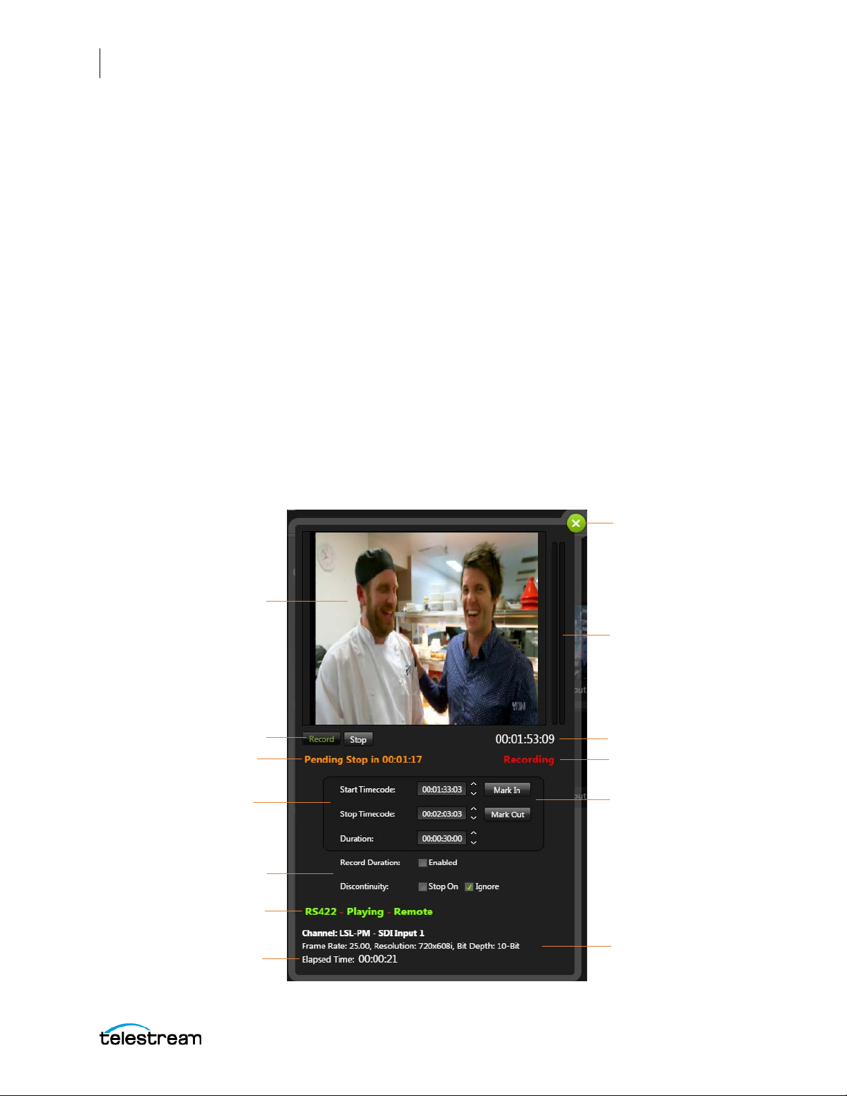
90
Real-time Preview from VTR
Close the dialog
Operation Controls
Start / Stop / Duration
Timecode
Current Timecode
Audio Level Meters
Input and Video
Information
Select Mark In or
Mark Out Points
Duration and Discontinuity
Options
RS-422 Status
Present Capture State
Elapsed Time of Current
Recording
Pending Capture State
The Lightspeed Live Capture Web Application
Using the Lightspeed Live Capture Web App
VTR Mode Controls and Indicators
When the Capture action Trigger option is set to VTR mode, the Channel Control dialog
provides information about the selected channel and controls for the operation of the
channel when connected to a VTR. You need to create a VTR Capture Workflow to
enable operation of the VTR Channel Control dialog. See Creating a VTR Capture
Workflow for complete instructions.
Using the Channel Control dialog you can control an external VTR via RS-422 for the
purposes of media ingest from tape. The user enters the Start timecode (Mark In) where
the capture recording will begin and either a Stop timecode (Mark Out) or duration to
determine where the recording will stop.
The user can then press Record to command the VTR to cue up the tape to the Start
timecode minus a 3 second pre-roll, proceeding then into the play state where
recording begins at the Start timecode and stops based on the Duration or Stop
timecode, depending on the Record Duration option chosen.
RS-422 Interface Device
The 4-Port RS-422 Interface Kit is required to connect a VTR to the Lightspeed Live server.
See Appendix B: Installing the RS-422 Interface Kit for installation instructions.
Click on a channel to open its Channel Control dialog, as shown below.
Lightspeed Live Guide
Page 91
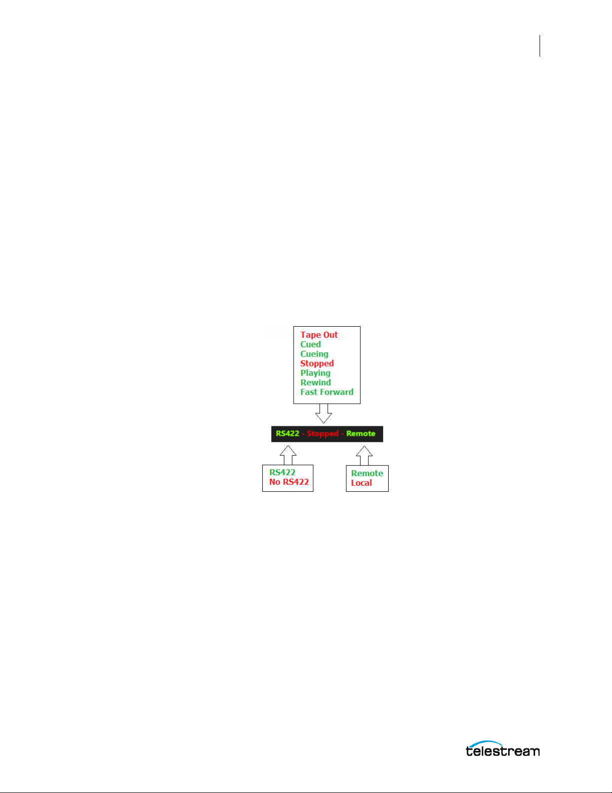
The Lightspeed Live Capture Web Application
Using the Lightspeed Live Capture Web App
Controls for VTR Mode
The following controls are provided in the Channel Control dialog when the Trigger
mode is set to VTR in the Capture action:
Record
Click Record to initiate the recording process, based on the settings made for Start
Timecode, Stop Timecode, Duration, and Discontinuity.
Stop
Click to stop the recording operation.
RS422 Status Indicators
• RS422 Status—Provides status of the VTR that is connected to this input channel.
The status of the VTR is displayed in three ways: the RS422 state, the transport state
of a detected VTR, and the remote control state of a detected VTR.
RS422 State – VTR Transport State – Remote Control State
The following status messages are presented.
91
Lightspeed Live Guide
– RS422 State:
RS422—A VTR with RS-422 control is detected and is connected to the RS-422
port of the source input.
No RS422—There is no connected VTR that is under RS-422 control.
– VTR Transport State:
The current VTR transport state is displayed when a VTR under RS-422 control is
detected.
Tape Out—There is no tape loaded into the VTR.
Cued—The VTR tape is cued up.
Cueing—The VTR is in the process of cuing up.
Stopped—The VTR is currently stopped, with a tape in it.
Playing—The VTR is currently playing.
Rewind—The VTR is in rewind mode.
Page 92
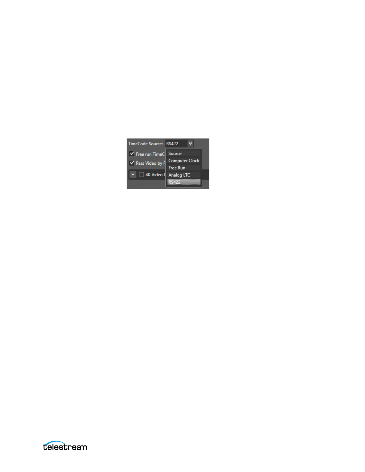
92
The Lightspeed Live Capture Web Application
Using the Lightspeed Live Capture Web App
Fast Forward—The VTR is in fast forward mode.
– Remote Control State:
Remote—A VTR under RS-422 control is detected and set to enable control by
the Capture user interface.
Local—A VTR under RS-422 control is detected and set to operate only with its
built-in controls.
• Current Timecode—Displays the current timecode of the VTR, when the
TimeCode Source is set to RS-422 in the Vantage Management Console. See Config-
uring SDI Source Options for more information on setting this option.
• Pending Capture State—Displays the Pending status of the Capture operation of
Pending Record, Pending Pause, Pending Resume, or Pending Stop. See Indicators
and Information in the Channel Control Dialog above for a complete listing and
description of the Pending Capture State indicators.
• Present Capture State—Displays the Present status of the Capture operation of
Ready, Recording, or Paused. See Indicators and Information in the Channel Control
Dialog above for a complete listing and description of the Present Capture State
indicators.
VTR Timecode and Duration Settings
Specify VTR timecode ranges or durations to capture during the record operation.
• Start Timecode—Enter the desired Start Timecode to be used for recording. When
Record is selected Lightspeed Live Capture will cue up the tape to this Start Timecode, minus a 3 second pre-roll, then start playing forward to begin recording.
– Mark In—Sets the current time location as the Start Timecode.
• Stop Timecode—Enter the desired Stop Timecode. This parameter is ignored
when Record Duration is enabled.
– Mark Out—Sets the current time location as the Stop Timecode.
• Duration—Enter a desired Duration to record. This also indicates the duration set
to record between the Start and Stop Timecodes. This parameter is ignored when
Record Duration is not enabled.
• Record Duration—When the Record Duration option is checked, capture record-
ing will ignore the Stop Timecode and will stop when the Duration entered is
reached, including the last frame. If unchecked, the recording will stop when the
Stop Timecode is reached, and the last frame is not included in the captured file.
Lightspeed Live Guide
Page 93
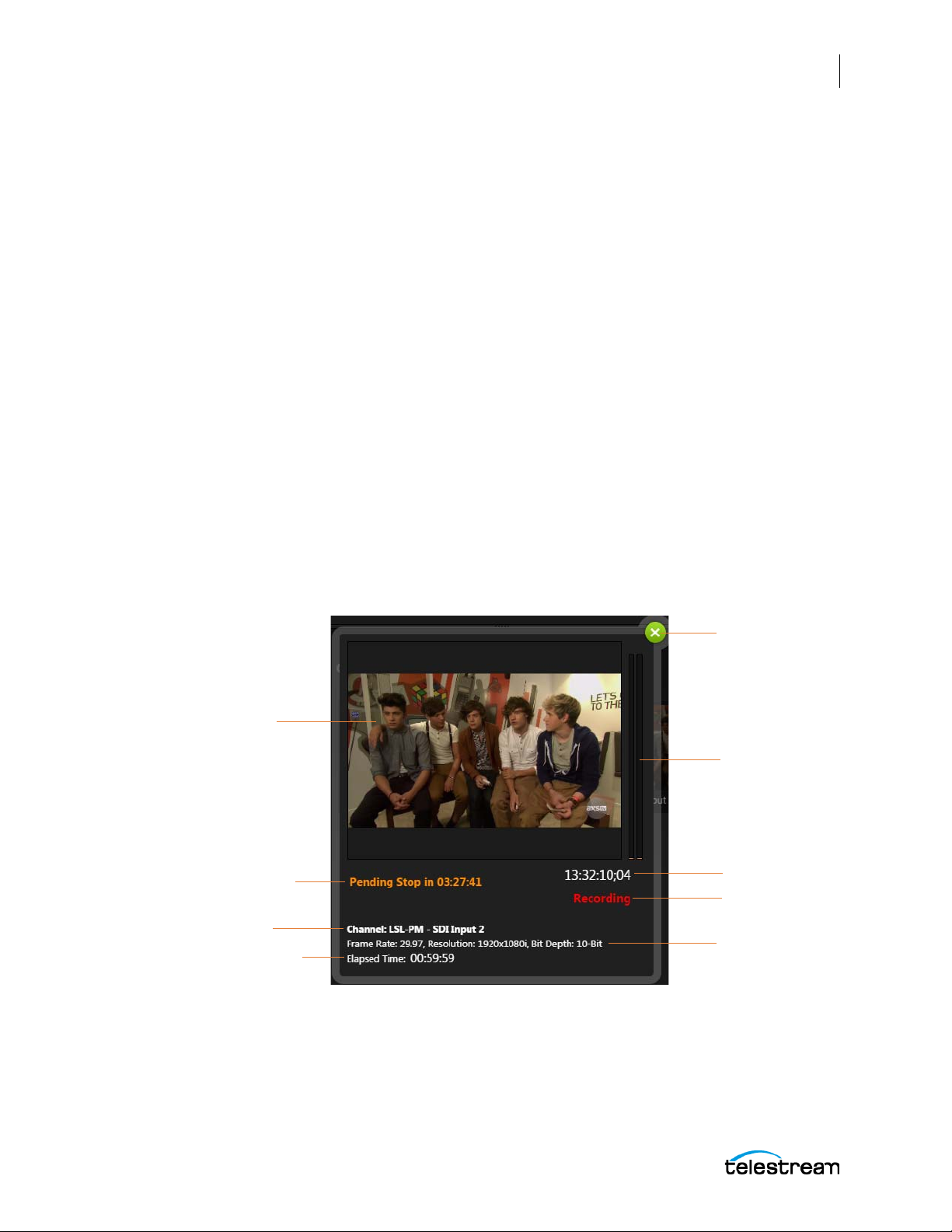
The Lightspeed Live Capture Web Application
Video View Panel
Close the Dialog
Source Name and Input ID
Timecode
Audio Level Meters
Video Information
Present Capture
State
Elapsed Time of Current
Recording
Pending Capture State
Using the Lightspeed Live Capture Web App
• Discontinuity—Select Stop On if you want the recording to stop when a timecode
discontinuity is detected. Select Ignore to disregard any timecode discontinuity if
they are detected.
Schedule and Web Service Controls and Indicators
When the Capture action Trigger option is set either to Schedule or Web Service mode
the Channel Control dialog provides display of the video source and information about
the present operating state of the selected channel. See Capture Action in Appendix A
for more information on setting the Trigger option.
Due to the unique nature of a Schedule or Web Service trigger, more than one job may
be queued up for processing. The status information displayed for these triggers will
vary depending on whether a single job is queued or multiple jobs are queued.
Click on a channel to open its Channel Control dialog.
When a Single Event is Queued for Capture
93
The information shown in the following image is available when there is just one
Schedule or Web Service job in the Capture queue. See the previous sections for
detailed descriptions of the information that is displayed.
Lightspeed Live Guide
Page 94
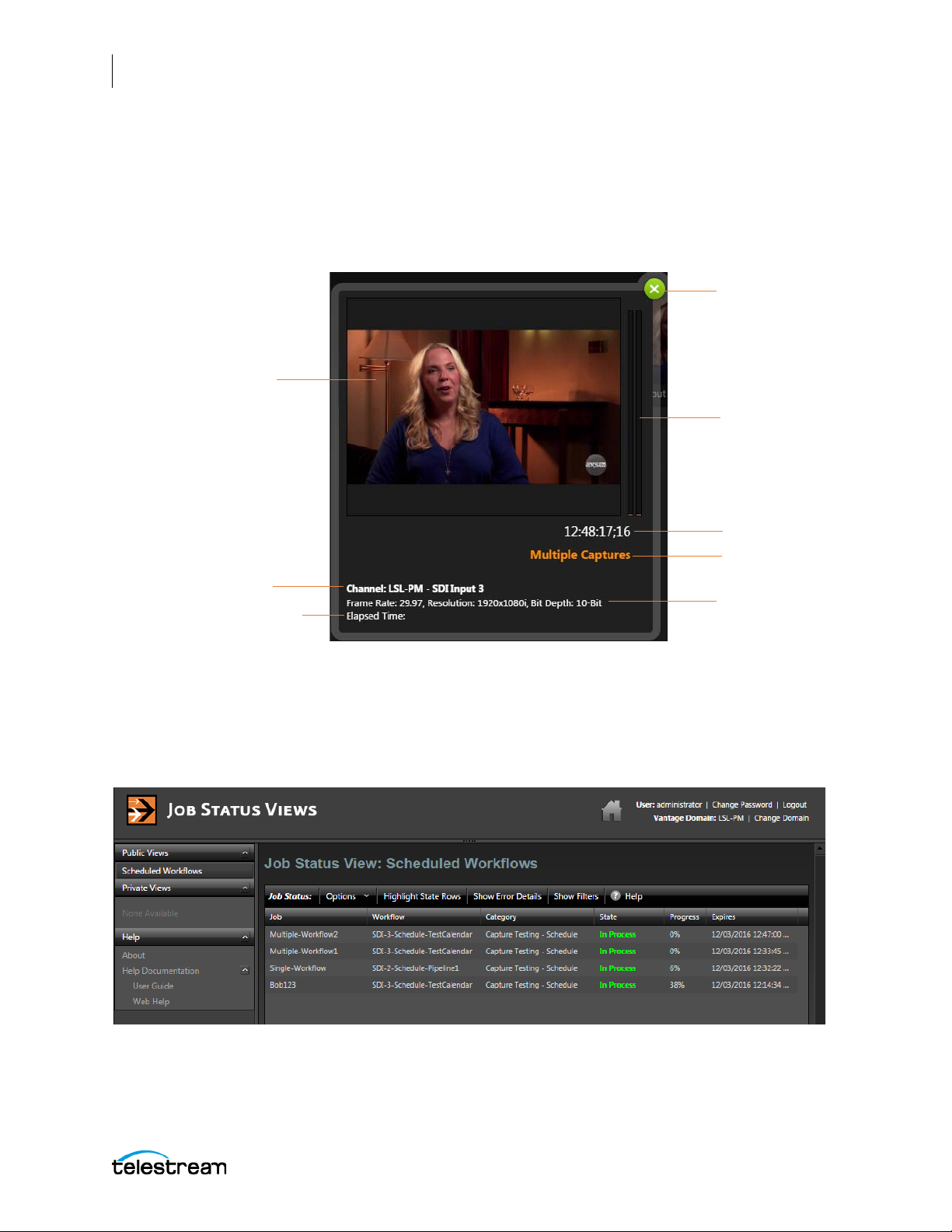
94
Video View Panel
Close the Dialog
Source Name and Input ID
Timecode
Audio Level Meters
Video Information
Present Capture
State
Elapsed Time of Current
Recording
The Lightspeed Live Capture Web Application
Using the Lightspeed Live Capture Web App
When Multiple Events are Queued for Capture
Capture events for Schedule are queued up for processing when they are within 1 hour
of their start time and Web Service events can be queued up any time within a 24 hour
period. When more than one event is in the Capture queue, the Present Capture State
indicator displays Multiple Captures, as shown on the following image.
Viewing Information about Multiple Capture Jobs
When in the Multiple Captures state, you will need to go to the Job Status Views page
to see a list of the Capture jobs that are in the queue, and to view information about
their current status.
See Using the Job Status Views for more information about accessing and using the Job
Status Views application.
Lightspeed Live Guide
Page 95
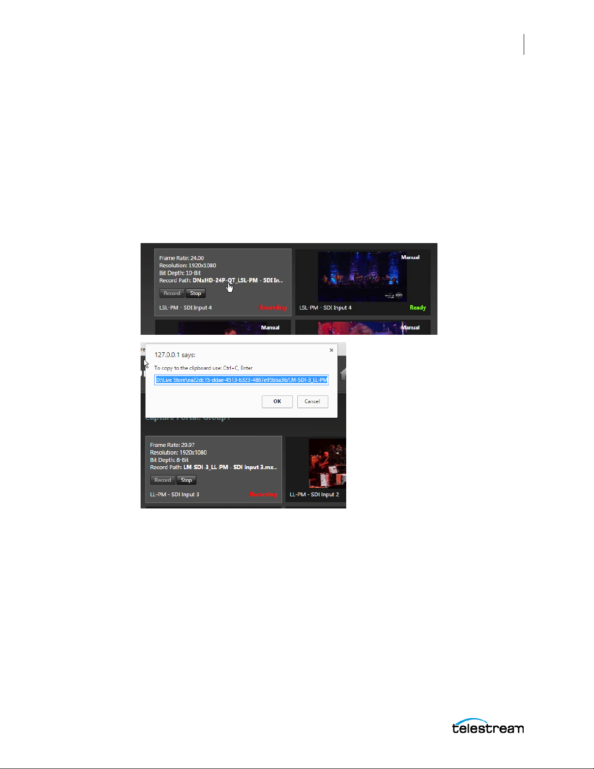
Recorded File Location and Format
When recording is active, captures are written to the Live Store, or the path specified
within the Vantage Capture action under Output Location in the Primary Output or
Secondary Output.
The Primary Output and Secondary Output in the Vantage Capture action also allow
you to select the container format and the video and audio encoders to use for the
captured output. See Primary and Secondary Outputs for more information.
When actively recording you can click on the Record Path link to open a dialog that
provides the option to copy the link of the record path location. This path can be
copied and pasted into Windows Explorer to access the output file:
The Lightspeed Live Capture Web Application
Using the Lightspeed Live Capture Web App
95
Lightspeed Live Guide
Page 96
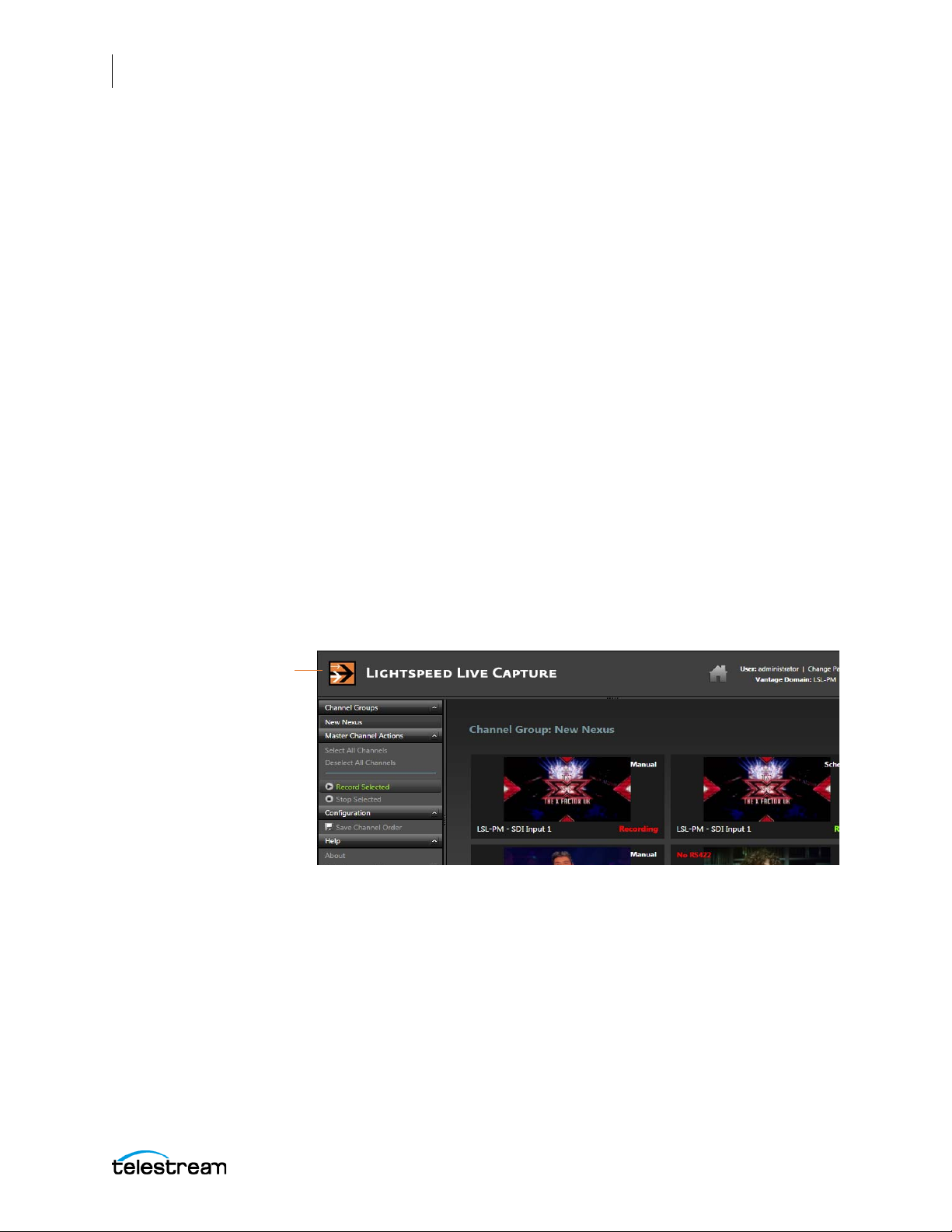
96
Click the Home button to
access the home page
The Lightspeed Live Capture Web Application
Using the Job Status Views
Using the Job Status Views
Job Status Views is a web application that enables basic Vantage job management via a
web browser. You can use Job Status Views to access job information and manage jobs
in your Vantage domain from anywhere on the LAN, or via the Internet if you provide
such access to your Vantage domain.
You can use the Job Status Views web application to do the following:
• Display information about submitted jobs
• Sort and filter job entries
• Highlight and identify jobs in different states
• Troubleshoot job processing issues
The views that you see in Job Status Views are defined by Vantage administrators, who
control which job information displays and which job control functions (such as the
ability to delete a job) are allowed. Views may be public or private and are configured in
the Vantage Management Console. Public views are available to everyone, and private
views are for use by specified Vantage users.
Opening Job Status Views
To open Job Status Views, first click the Home button in the title panel to access the
Vantage Web Applications home page.
Lightspeed Live Guide
Page 97
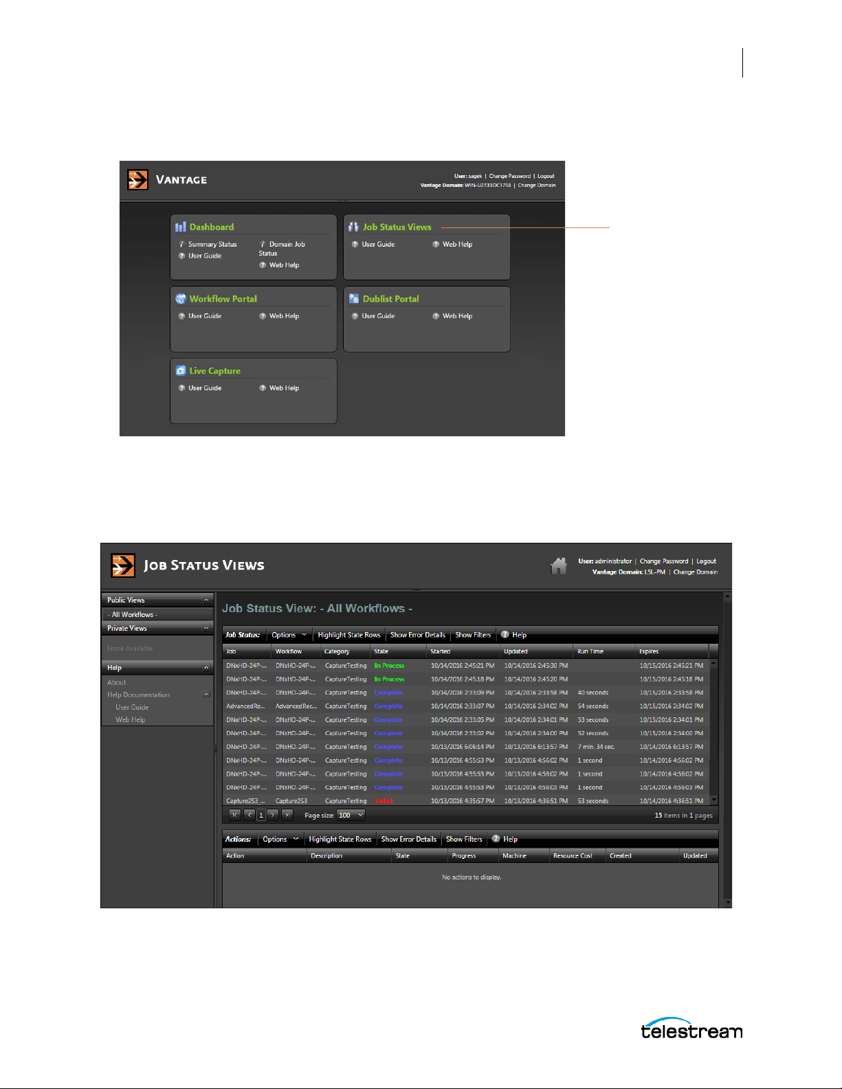
The Lightspeed Live Capture Web Application
Open Job Status Views
Using the Job Status Views
On the Vantage Web Applications home page, click Job Status Views.
97
The Job Status Views Web Application
The following shows an example of information provided in the Job Status Views web
application, this example is set to display All Workflows.
Lightspeed Live Guide
Page 98

98
The Lightspeed Live Capture Web Application
Using the Job Status Views
If no job status information is appearing in Job Status Views, you should make sure that
this feature has been enabled in the Vantage Management Console. Open the Vantage
Management Console and select Application Configurations > Job Status Views. Check
the Enable option, shown in the red circle in the image below, then click the Save icon.
For more details on customizing the Job Status Views see Using the Job Status Views
Web Application in the Vantage User’s Guide. This guide is available from the User Guide
or Web Help link in the Help section of the left panel Job Status Views web application.
Lightspeed Live Guide
Page 99

Creating Capture Workflows
This chapter provides information to help calculate Lightspeed Live Capture resource
usage, and tours that describe typical examples of configuring and capturing live
content.
The following topics are included:
■ Lightspeed Live Capture Resource Calculator
99
■ Determining the Time-Shift Buffer Duration
■ Calculating your Resource Usage Capacity
Page 100

100
Creating Capture Workflows
Lightspeed Live Capture Resource Calculator
Lightspeed Live Capture Resource Calculator
Lightspeed Live Capture uses a variety of codecs and format containers to capture live
video into media files. At the simplest level, Lightspeed Live Capture consists of
customizable workflow actions that automate the live capture process. A workflow is
the mechanism you create that takes an incoming live source and encodes it into one
of many available codec and container formats.
Note: When Live Capture and Live Stream are being used on the same Lightspeed
Live server, use the Live Stream CPU and GPU Resource Usage Guide (located in the
Creating Stream Channels chapter) along with the Live Capture Resource Calculator
describe here to determine how Capture and Stream can best share a Lightspeed Live
server's resources.
The Lightspeed Live server has four (4) SD/HD/3G-SDI inputs that can be used to
capture up to four (4) SD/HD formatted files or one (1) UHD/4K formatted file. One or
more Lightspeed Live Capture workflows can be driven by a single source input. This
allows the user to configure their system to create more than one output format type
from a single source input. For example, if your capture workflow requires two hi-res
capture output files, such as DNxHD 220 and Apple ProRes HQ, Lightspeed Live Capture
can be used for this by creating two Capture origin actions that use the same source
input.
The figure below shows four (4) SDI-HD inputs. SDI Input 1 is connected to two (2)
workflows, and SDI Input 2, 3, and 4 are each connected to a single workflow.
The input source/workflow flexibility described above, combined with the wide array of
codecs available on a Lightspeed Live server, make it important that all processes being
performed on a Lightspeed Live server do not exceed its total processing capabilities.
Lightspeed Live Guide
 Loading...