

Page 1
Lightspeed Live Capture Guide
Live Capture 3.0 with ComponentPac 7.2
June 2019 277130
Page 2

2
Copyrights and Trademark Notices
Copyrights and Trademark Notices
Copyright © 2019 Telestream, LLC. All rights reserved worldwide. No part of this
publication may be reproduced, transmitted, transcribed, altered, or translated into any
languages without the written permission of Telestream. Information and
specifications in this document are subject to change without notice and do not
represent a commitment on the part of Telestream.
Te le s t re a m. Telestream, CaptionMaker, Episode, Flip4Mac, FlipFactory, Flip Player,
Gameshow, GraphicsFactory, Lightspeed, MetaFlip, Post Producer, ScreenFlow, Splitand-Stitch, Switch, Tempo, TrafficManager, Vantage, VOD Producer and Wirecast, are
registered trademarks and Cricket, e-Captioning, iQ, iVMS, iVMS ASM, Inspector,
MacCaption, Pipeline, Vantage Cloud Port, Vidchecker, and Surveyor are trademarks of
Telestream, LLC. All other trademarks are the property of their respective owners.
Adobe. Adobe® HTTP Dynamic Streaming Copyright © 2014 Adobe Systems. All rights
reserved.
Apple. QuickTime, MacOS X, and Safari are trademarks of Apple, Inc. Bonjour, the
Bonjour logo, and the Bonjour symbol are trademarks of Apple, Inc.
Avid. Portions of this product Copyright 2012 Avid Technology, Inc.
CoreOS. Developers of ETCD.
Dolby. Dolby and the double-D symbol are registered trademarks of Dolby
Laboratories.
Fraunhofer IIS and Thomson Multimedia. MPEG Layer-3 audio coding technology
licensed from Fraunhofer IIS and Thomson Multimedia.
Google. VP6 and VP8 Copyright Google Inc. 2014 All rights reserved.
MainConcept. MainConcept is a registered trademark of MainConcept LLC and
MainConcept AG. Copyright 2004 MainConcept Multimedia Technologies.
Manzanita. Manzanita is a registered trademark of Manzanita Systems, Inc.
MCW. HEVC Decoding software licensed from MCW.
MediaInfo. Copyright © 2002-2013 MediaArea.net SARL. All rights reserved.
THIS SOFTWARE IS PROVIDED BY THE COPYRIGHT HOLDERS AND CONTRIBUTORS “AS
IS” AND ANY EXPRESS OR IMPLIED WARRANTIES, INCLUDING, BUT NOT LIMITED TO, THE
IMPLIED WARRANTIES OF MERCHANTABILITY AND FITNESS FOR A PARTICULAR
PURPOSE ARE DISCLAIMED. IN NO EVENT SHALL THE COPYRIGHT HOLDER OR
CONTRIBUTORS BE LIABLE FOR ANY DIRECT, INDIRECT, INCIDENTAL, SPECIAL,
EXEMPLARY, OR CONSEQUENTIAL DAMAGES (INCLUDING, BUT NOT LIMITED TO,
PROCUREMENT OF SUBSTITUTE GOODS OR SERVICES; LOSS OF USE, DATA, OR PROFITS;
OR BUSINESS INTERRUPTION) HOWEVER CAUSED AND ON ANY THEORY OF LIABILITY,
WHETHER IN CONTRACT, STRICT LIABILITY, OR TORT (INCLUDING NEGLIGENCE OR
OTHERWISE) ARISING IN ANY WAY OUT OF THE USE OF THIS SOFTWARE, EVEN IF
ADVISED OF THE POSSIBILITY OF SUCH DAMAGE.
Lightspeed Live Capture User Guide
Page 3

Copyrights and Trademark Notices
Microsoft. Microsoft, Windows NT|2000|XP|XP Professional|Server 2003|Server 2008
|Server 2012, Windows 7, Windows 8, Windows 10, Media Player, Media Encoder, .Net,
Internet Explorer, SQL Server 2005|2008|Server 2012, and Windows Media Technologies
are trademarks of Microsoft Corporation.
NLOG, MIT, Apache, Google. NLog open source code used in this product under MIT
License and Apache License is copyright © 2014-2016 by Google, Inc., © 2016 by Stabzs,
© 2015 by Hiro, Sjoerd Tieleman, © 2016 by Denis Pushkarev, © 2015 by Dash Industry
Forum. All rights reserved.
SharpSSH2. SharpSSH2 Copyright (c) 2008, Ryan Faircloth. All rights reserved.
Redistribution and use in source and binary forms, with or without modification, are
permitted provided that the following conditions are met:
Redistributions of source code must retain the above copyright notice, this list of
conditions and the following disclaimer.
Redistributions in binary form must reproduce the above copyright notice, this list of
conditions and the following disclaimer in the documentation and/or other materials
provided with the distribution.
3
Neither the name of Diversified Sales and Service, Inc. nor the names of its contributors
may be used to endorse or promote products derived from this software without
specific prior written permission.
THIS SOFTWARE IS PROVIDED BY THE COPYRIGHT HOLDERS AND CONTRIBUTORS “AS
IS” AND ANY EXPRESS OR IMPLIED WARRANTIES, INCLUDING, BUT NOT LIMITED TO, THE
IMPLIED WARRANTIES OF MERCHANTABILITY AND FITNESS FOR A PARTICULAR
PURPOSE ARE DISCLAIMED. IN NO EVENT SHALL THE COPYRIGHT OWNER OR
CONTRIBUTORS BE LIABLE FOR ANY DIRECT, INDIRECT, INCIDENTAL, SPECIAL,
EXEMPLARY, OR CONSEQUENTIAL DAMAGES (INCLUDING, BUT NOT LIMITED TO,
PROCUREMENT OF SUBSTITUTE GOODS OR SERVICES; LOSS OF USE, DATA, OR PROFITS;
OR BUSINESS INTERRUPTION) HOWEVER CAUSED AND ON ANY THEORY OF LIABILITY,
WHETHER IN CONTRACT, STRICT LIABILITY, OR TORT (INCLUDING NEGLIGENCE OR
OTHERWISE) ARISING IN ANY WAY OUT OF THE USE OF THIS SOFTWARE, EVEN IF
ADVISED OF THE POSSIBILITY OF SUCH DAMAGE.
Swagger. Licensed from SmartBear.
Te le r i k. RadControls for ASP.NET AJAX copyright Telerik All rights reserved.
Voi ce Age . This product is manufactured by Telestream under license from VoiceAge Corporation.
x264 LLC. The product is manufactured by Telestream under license from x264 LLC.
Xceed. The Software is Copyright ©1994-2012 Xceed Software Inc., all rights reserved.
Lightspeed Live Capture User Guide
Page 4

4
Copyrights and Trademark Notices
ZLIB. Copyright (C) 1995-2013 Jean-loup Gailly and Mark Adler.
Other brands, product names, and company names are trademarks of their respective
holders, and are used for identification purpose only.
MPEG Disclaimers
MPEGLA MPEG2 Patent
ANY USE OF THIS PRODUCT IN ANY MANNER OTHER THAN PERSONAL USE THAT
COMPLIES WITH THE MPEG-2 STANDARD FOR ENCODING VIDEO INFORMATION FOR
PACKAGED MEDIA IS EXPRESSLY PROHIBITED WITHOUT A LICENSE UNDER APPLICABLE
PATENTS IN THE MPEG-2 PATENT PORTFOLIO, WHICH LICENSE IS AVAILABLE FROM
MPEG LA, LLC, 4600 S. Ulster Street, Suite 400, Denver, Colorado 80237 U.S.A.
MPEGLA MPEG4 VISUAL
THIS PRODUCT IS LICENSED UNDER THE MPEG-4 VISUAL PATENT PORTFOLIO LICENSE
FOR THE PERSONAL AND NON-COMMERCIAL USE OF A CONSUMER FOR (i) ENCODING
VIDEO IN COMPLIANCE WITH THE MPEG-4 VISUAL STANDARD (“MPEG-4 VIDEO”) AND/
OR (ii) DECODING MPEG-4 VIDEO THAT WAS ENCODED BY A CONSUMER ENGAGED IN A
PERSONAL AND NON-COMMERCIAL ACTIVITY AND/OR WAS OBTAINED FROM A VIDEO
PROVIDER LICENSE IS GRANTED OR SHALL BE IMPLIED FOR ANY OTHER USE.
ADDITIONAL INFORMATION INCLUDING THAT RELATING TO PROMOTIONAL, INTERNAL
AND COMMERCIAL USES AND LICENSING MAY BE OBTAINED FROM MPEG LA, LLC. SEE
HTTP://WWW.MPEGLA.COM.
MPEGLA AVC
THIS PRODUCT IS LICENSED UNDER THE AVC PATENT PORTFOLIO LICENSE FOR THE
PERSONAL USE OF A CONSUMER OR OTHER USES IN WHICH IT DOES NOT RECEIVE
REMUNERATION TO (i) ENCODE VIDEO IN COMPLIANCE WITH THE AVC STANDARD
(“AVC VIDEO”) AND/OR (ii) DECODE AVC VIDEO THAT WAS ENCODED BY A CONSUMER
ENGAGED IN A PERSONAL ACTIVITY AND/OR WAS OBTAINED FROM A VIDEO PROVIDER
LICENSED TO PROVIDE AVC VIDEO. NO LICENSE IS GRANTED OR SHALL BE IMPLIED FOR
ANY OTHER USE. ADDITIONAL INFORMATION MAY BE OBTAINED FROM MPEG LA, L.L.C.
SEE HTTP://WWW.MPEGLA.COM.
Lightspeed Live Capture User Guide
Page 5

MPEG4 SYSTEMS
THIS PRODUCT IS LICENSED UNDER THE MPEG-4 SYSTEMS PATENT PORTFOLIO LICENSE
FOR ENCODING IN COMPLIANCE WITH THE MPEG-4 SYSTEMS STANDARD, EXCEPT THAT
AN ADDITIONAL LICENSE AND PAYMENT OF ROYALTIES ARE NECESSARY FOR
ENCODING IN CONNECTION WITH (i) DATA STORED OR REPLICATED IN PHYSICAL MEDIA
WHICH IS PAID FOR ON A TITLE BY TITLE BASIS AND/OR (ii) DATA WHICH IS PAID FOR ON
A TITLE BY TITLE BASIS AND IS TRANSMITTED TO AN END USER FOR PERMANENT
STORAGE AND/OR USE. SUCH ADDITIONAL LICENSE MAY BE OBTAINED FROM MPEG LA,
LLC. SEE HTTP://WWW.MPEGLA.COM FOR ADDITIONAL DETAILS.
Limited Warranty and Disclaimers
Telestream, LLC (the Company) warrants to the original registered end user that the
product will perform as stated below for a period of one (1) year from the date of
shipment from factory:
Hardware and Media—The Product hardware components, if any, including equipment
supplied but not manufactured by the Company but NOT including any third party
equipment that has been substituted by the Distributor for such equipment (the
“Hardware”), will be free from defects in materials and workmanship under normal
operating conditions and use.
5
Copyrights and Trademark Notices
Warranty Remedies
Your sole remedies under this limited warranty are as follows:
Hardware and Media—The Company will either repair or replace (at its option) any
defective Hardware component or part, or Software Media, with new or like new
Hardware components or Software Media. Components may not be necessarily the
same, but will be of equivalent operation and quality.
Software Updates
Except as may be provided in a separate agreement between Telestream and You, if
any, Telestream is under no obligation to maintain or support the Software and
Telestream has no obligation to furnish you with any further assistance, technical
support, documentation, software, update, upgrades, or information of any nature or
kind.
Restrictions and Conditions of Limited Warranty
This Limited Warranty will be void and of no force and effect if (i) Product Hardware or
Software Media, or any part thereof, is damaged due to abuse, misuse, alteration,
neglect, or shipping, or as a result of service or modification by a party other than the
Company, or (ii) Software is modified without the written consent of the Company.
Lightspeed Live Capture User Guide
Page 6

6
Copyrights and Trademark Notices
Limitations of Warranties
THE EXPRESS WARRANTIES SET FORTH IN THIS AGREEMENT ARE IN LIEU OF ALL OTHER
WARRANTIES, EXPRESS OR IMPLIED, INCLUDING, WITHOUT LIMITATION, ANY
WARRANTIES OF MERCHANTABILITY OR FITNESS FOR A PARTICULAR PURPOSE. No oral
or written information or advice given by the Company, its distributors, dealers or
agents, shall increase the scope of this Limited Warranty or create any new warranties.
Geographical Limitation of Warranty—This limited warranty is valid only within the
country in which the Product is purchased/licensed.
Limitations on Remedies—YOUR EXCLUSIVE REMEDIES, AND THE ENTIRE LIABILITY OF
TELESTREAM, LLC WITH RESPECT TO THE PRODUCT, SHALL BE AS STATED IN THIS
LIMITED WARRANTY. Your sole and exclusive remedy for any and all breaches of any
Limited Warranty by the Company shall be the recovery of reasonable damages which,
in the aggregate, shall not exceed the total amount of the combined license fee and
purchase price paid by you for the Product.
Damages
TELESTREAM, LLC SHALL NOT BE LIABLE TO YOU FOR ANY DAMAGES, INCLUDING ANY
LOST PROFITS, LOST SAVINGS, OR OTHER INCIDENTAL OR CONSEQUENTIAL DAMAGES
ARISING OUT OF YOUR USE OR INABILITY TO USE THE PRODUCT, OR THE BREACH OF
ANY EXPRESS OR IMPLIED WARRANTY, EVEN IF THE COMPANY HAS BEEN ADVISED OF
THE POSSIBILITY OF THOSE DAMAGES, OR ANY REMEDY PROVIDED FAILS OF ITS
ESSENTIAL PURPOSE.
Further information regarding this limited warranty may be obtained by writing:
Telestream, LLC
848 Gold Flat Road
Nevada City, CA 95959 USA
You can call Telestream during U. S. business hours via telephone at (530) 470-1300.
Regulatory Compliance
Electromagnetic Emissions: FCC Class A, EN 55022 Class A, EN 61000-3-2/-3-3, CISPR 22
Class A
Electromagnetic Immunity: EN 55024/CISPR 24, (EN 61000-4-2, EN 61000-4-3, EN
61000-4-4, EN 61000-4-5, EN 61000-4-6, EN 61000-4-8, EN 61000-4-11)
Safety: CSA/EN/IEC/UL 60950-1 Compliant, UL or CSA Listed (USA and Canada), CE
Marking (Europe)
California Best Management Practices Regulations for Perchlorate Materials:
This Perchlorate warning applies only to products containing CR (Manganese Dioxide)
Lithium coin cells. Perchlorate Material-special handling may apply. See
www.dtsc.ca.gov/hazardouswaste/perchlorate.
Lightspeed Live Capture User Guide
Page 7

Contents
Copyrights and Trademark Notices 2
Introducing Lightspeed Live Stream and Capture 23
Overview 24
Lightspeed Live Server Platform 24
Lightspeed Live Stream 25
Lightspeed Live Capture 25
Using Live Stream and Live Capture Concurrently 26
Shared Resource Allocation 26
Certain Stream Sources are Not Supported for Capture Use 26
Lightspeed Live Capture Web API Reference 27
Lightspeed Live Application Program Interfaces 27
Lightspeed Live Stream Web API 27
Lightspeed Live Capture Web API 27
Lightspeed Live Source Web API 27
Lightspeed Live Server Hardware Specifications and Components 28
System Power 29
Drives 29
Front Control Panel 29
Cooling System 29
SDI Input Cards 30
SDI Card Input Formats 30
GPU 31
Expansion Input Card Slots 31
RS-422 VTR Interface Kit Option for Capture 31
Front Panel 32
Front Panel Features 32
Rear Panel 33
Video Input Connections 33
7
Installing and Maintaining the Server 35
Installing the Server 36
Page 8

8
Contents
Unpacking the Server 36
Installing the Optional USB Cable Retainer for the RS-422 VTR Control Interface 36
Rack Installation 37
Assembling the Rails 37
Installing Outer Rails into a Rack 37
Installing the Server in the Rack 38
Making Connections 40
Data and Signal Connections 40
Power Requirements and Connections 41
Power and General Cautions and Warnings 41
Installing the Optional RS422 VTR Interface Kit 42
Managing the Operating System 43
Microsoft Activation Key 43
Microsoft Updates 43
Windows User ID and Password 43
Windows Firewall 43
Maintaining the Lightspeed Server 44
Performance Tuning a Lightspeed Live Server 44
Backing up the Lightspeed Live Server 47
Managing the Lightspeed Live Server 48
Installing New or Replacement Hard Drives 49
Rebuilding the Lightspeed Live Storage RAID 50
Replacing Power Supplies 50
Replacing the Power Supply 50
Monitoring Lightspeed Live via SNMP 51
Enabling SNMP Monitoring 51
Configuring the Lightspeed Live Capture Server and Apps 53
Changing a Source Name 54
Managing and Configuring Sources 55
Sources Overview 56
Source and Channel Indicator Icons 57
Configuring an SDI Source 58
Switching Between HD and UHD Configurations 61
Configuring a File Loop Source 63
Configuring a Transport Stream Source 64
Configuring an RTMP Source 66
Managing and Configuring Audio Tracks 67
Adding an Audio Track 67
Previewing the Audio Tracks 67
Configuring an Audio Track 68
Configuring Capture Resources 69
Configuring Settings for Your Facility 70
Using Inputs for Both Live Stream and Capture 75
Configuring Ingest Sources 76
Configuring a Channel Group Nexus 76
Using Capture Inventory to Preview and Find Workflows Used by an Input 78
Page 9

Previewing Sources 79
Finding Workflows 79
Installing the Live Capture & Tape Capture Web Apps 80
Installation on Standard Servers 80
Clear Browsing Data after Updating 80
Renaming or Reconfiguring Servers 81
Array Licensing for Multiple Server Live Capture Systems 84
Vantage and Live Capture Solutions 84
New Vantage Systems Containing Live Capture 84
Adding Live Capture to an Existing Vantage Domain Array 84
Important Notes on Configuring Non-Capture Workflow Actions on Multiple Server
Systems
85
Joining Multiple Capture Servers 86
Best Practice When Joining Two or More Live Capture Servers Into a Single Do-
main
86
Joining Capture-Only Systems 87
Existing Vantage Array - Adding Live Capture Server(s) 88
Uniquely Named Multiple Capture Servers 89
Best Practice for Multiple Live Capture Server System Design 90
Connecting the Applications for Multiple Servers 92
Configuring Vantage Client Applications for Multiple Servers 92
Using the Live Capture Web App with Multiple Servers 93
Using NetBIOS Hostnames Instead of External Name Server 94
Correcting Thumbnail Appearance on Non-Local Systems 96
Apple Computer Procedure to Correct Thumbnail Appearance 96
Windows Computer Procedure to Correct Thumbnail Appearance 96
Updating Capture using Secured Version Control and ComponentPacs 97
Clear Browsing Data after Updating Vantage or Live Capture 98
Contents
9
Creating Capture & Tape Action Workflows 99
Additional Information 99
Creating and Activating the Capture Action Workflow 100
Capture Action Overview 101
Program 102
Expected Labels 104
Trigger Settings 105
DAI Trigger 105
Manual Trigger 107
Recurring Segment Trigger 107
Schedule Trigger 108
Web Service Trigger 109
Using the Schedule Trigger 110
What Happens When a Queued Event is Deleted 110
Creating Repeating Events in Google Calendar 110
Adjusting your Google Account Settings for Live Capture Access 111
Creating a Schedule Trigger 112
Primary and Secondary Outputs 115
Page 10

10
Contents
Time Code Burn-in Filter 117
Creating a Capture Action Workflow 118
Creating Avid Workflows 121
Important Note Regarding Licensing Live Capture Systems for Avid Interplay Work-
flows 123
Required Avid Components are Installed by User or Avid 123
Single Resolution Avid Workflow 123
Multiple Resolution Avid Interplay Workflow 124
Creating and Activating the Tape Action Workflow 125
Tape Action Overview 126
Inputs 126
Expected Labels 127
Primary and Secondary Outputs 127
Settings Panel 128
Time Code Burn-in Filter 132
Creating the Tape Action Workflow 133
Binding Variables to Configuration Parameters 135
Configuring Variables in the Tape Capture Web Application 135
Configuring Variables in the Live Capture Web Application 135
Enabling Open Workflows 136
Open Workflow Capability is Inherited from Live Capture and Tape Actions 136
Using the Live Capture Web Application 137
Live Capture Classic Web Application 137
Prerequisites to Using Live Capture 138
Accessing the Lightspeed Live Capture Web App 139
Creating and Using External Links 139
Create a Separate Account for Each User 140
Multiple User Access to the Capture or Tape Web Apps 140
Close Instances of the Web Application when Not in Use 140
Changing the Domain 140
Lightspeed Live Capture Web App Overview 141
What is a Channel? 141
Live Capture Controls and Operation Status 142
Title Panel 142
Selection Panel 142
Channel Previews Panel 143
Channel Previews Controls 144
Configuring the Custom Ganged Recording Defaults 146
Channel Controls 148
Trigger Type 149
Channel Options 150
Channel Recording Information 152
Display and Information Panel 153
Loss of Signal Behavior 155
Limited Bandwidth Behavior 156
Channel Status Panel 156
Filtering Job Status 157
Page 11

Triggers Determine the Method of Channel Control 158
DAI Trigger 158
Manual Trigger 160
Recurring Segment Trigger 161
Schedule Trigger 162
Web Service Trigger 162
Recorded File Location and Format 163
Selecting Output Encoders and Format 163
Deleting Captured Files 163
Using the Vantage Job Status Views 164
Opening Vantage Job Status Views 164
The Vantage Job Status Views Web Application 165
Configuring Job Status Views Information 166
Using the Tape Capture Web Application 167
Prerequisites to Using Tape Capture 168
Configuring the VTR Connection 169
Checking the VTR Connection Status 170
Troubleshooting the VTR Connection 170
Accessing the Lightspeed Tape Capture Web App 172
Changing the Domain 172
Tape Capture Overview 173
Tape Capture Controls and Operation Status 174
Selection Panel 174
Workflow/Status Panel 174
Log Panel 175
Clip Panel 176
Log 178
EDL File Import and Export 178
Capturing an Entire Tape 179
Timecode Break Recording 179
Tapes 182
Clip Log 182
Capturing Clips 183
Preview Player Panel 185
VTR Controls and Keyboard Shortcuts 186
Using the Tape Capture Web App 187
Setting up for Logging 187
Creating Tape Names 187
Creating a Clip 187
Configuring Clip Stitching 188
Capturing Clips 189
Configuring Tape Parameters that are Bound to Variables 190
Setting Drop/Non-Drop Frame Characteristics 191
Creating a Stitched Clip 192
Recording a Complete Tape - Even if It Has Errors 194
Using the Job Status View in Tape Capture 194
Contents
11
Page 12

12
Contents
Calculating Live Capture Resources 197
Lightspeed Live Capture Resource Calculator 198
Browser Operation is Not Included in Usage Calculations 199
Determining the Time-Shift Buffer Duration 199
Standard Definition (SD) Codecs 199
High Definition (HD) Codecs 199
UHD/4K Codecs 199
Calculating your Resource Usage Capacity 200
Resource Use Factor (RUF) Charts 201
Primary Outputs - RUF Values 201
Secondary Outputs - RUF Values 202
Example 1—Uses a Total of 1.00 RUF 203
Example 2—Uses a Total of 0.90 RUF 204
Capacity for Capturing Uncompressed Media Via 3G-SDI Inputs 205
Example 3—Uncompressed 10-bit - Uses a Total of 1 RUF 206
Example 4—Uncompressed 10-bit - Uses a Total of 1 RUF 207
Appendix A: Support 209
Obtaining Support | Information | Assistance 210
Return Material Authorization (RMA) Procedure 211
Using Log Files and Other Support Information 212
Log Files for Live Capture 212
Accessing the Log Files 212
Changing Log Content Settings 212
Downloading Log Files for Support 213
Resolving Capture Error Messages 215
Appendix B: Containers, Codecs, and Vantage Actions 217
Capture Action Output Containers 218
MXF OP1a Output 218
Generic MXF Format Summary 218
Video 218
Audio 218
Timecode 218
MXF Applicable Standards 219
Container Settings 219
General 219
Aspect Ratio Mode 220
Video Stream Details 220
Codec 220
AVC 220
Avid DNxHD 220
Avid DNxHR 220
DV 220
DVCPRO HD 221
IMX 221
Page 13

JPEG2000 Lossless (Comprimato) 221
JPEG2000 Lossy (Comprimato) 222
Panasonic AVC-Intra 223
Panasonic AVC-Ultra 223
Sony XAVC 223
Sony XDCAM 223
Uncompressed 223
x264 223
Time Code Burn-in Filter 224
Audio Stream Details 224
Codec (PCM) 224
General 224
MPEG2-TS Output 225
MPEG-2 TS Format Summary 225
Video 225
Audio 225
Container Settings 225
Video Stream Details 226
Codec 226
HEVC H/W 226
MPEG-2 227
x264 227
Time Code Burn-in Filter 228
Audio Stream Details 228
Codec 228
AAC Codec 229
General 229
PCM Codec 229
General 229
Channel Map 229
QuickTime Output 229
QuickTime Format Summary 229
Video 229
Audio 229
Container Settings 230
General 230
Aspect Ratio Mode 231
Clean Aperture 231
Video Stream Details 231
Codec 231
Apple ProRes 231
AVC 231
Avid DNxHD 232
Avid DNxHR 232
DV 232
DVCPRO HD 232
HEVC 232
HEVC (H/W) 232
Contents
13
Page 14

14
Contents
IMX 232
Panasonic AVC-Intra 232
Sony XDCAM 232
Uncompressed 232
x264 233
x265 233
Time Code Burn-in Filter 233
Audio Stream Details 234
Codec (PCM) 234
Channel Configuration 234
QuickTime 'Open' Output 235
QuickTime 'Open' Format Summary 235
Video 235
Audio 236
Container Settings 236
General 236
Important Information about Default Duration 236
Aspect Ratio Mode 238
Clean Aperture 238
Video Stream Details 238
Codec 238
Apple ProRes 238
Avid DNxHD 238
Avid DNxHR 239
Time Code Burn-in Filter 239
Audio Stream Details 239
Codec (PCM) 240
Channel Configuration 240
TIFO Output 240
TIFO Format Summary 241
Video 241
Audio 241
Container Settings 241
General 241
Aspect Ratio Mode 241
Video Stream Details 241
Codec 241
Apple ProRes 242
Avid DNxHD 242
Avid DNxHR 242
AVC 242
DV 242
DVCPRO HD 242
HEVC 243
HEVC H/W 243
IMX 243
JPEG2000 Lossless (Comprimato) 243
JPEG2000 Lossy (Comprimato) 244
Page 15

MPEG-2 245
Panasonic AVC-Intra 246
Panasonic AVC-Ultra 246
Sony XAVC 246
Sony XDCAM 246
Uncompressed 247
x264 247
x265 247
Time Code Burn-in Filter 248
Audio Stream Details 249
Codec (PCM) 249
Proxy TIFO Output 249
TIFO Format Summary 250
Video 250
Audio 250
Container Settings 250
General 250
Aspect Ratio Mode 250
Video Stream Details 250
Codec 250
AVC 251
DNxHD 251
Apple ProRes 251
Time Code Burn-in Filter 251
Audio Stream Details 252
Codec (PCM) 252
Proxy MP4 Output 252
Container Settings 253
Video Stream Details 253
Codec (AVC) 253
AVC 253
Audio Stream Details 253
Codec (AAC) 253
Proxy MXF RDD 25 Output 253
Container Settings 254
Video Stream Details 254
Codec (AVC) 254
AVC 254
Audio Stream Details 254
Codec (AAC) 254
AAC 255
255
Tape Action Output Containers 256
MXF OP1a Output 256
Generic MXF Format Summary 256
Video 256
Audio 256
Timecode 257
Contents
15
Page 16

16
Contents
MXF Applicable Standards 257
Output Settings 258
Container Settings 258
General 258
Aspect Ratio Mode 258
Video Stream Details 258
Codec 258
AVC 258
Avid DNxHD 259
DV 259
DVCPRO HD 259
IMX 259
JPEG2000 Lossless (Comprimato) 259
JPEG2000 Lossy (Comprimato) 260
Panasonic AVC-Intra 261
Panasonic AVC-Ultra 261
Sony XAVC 261
Sony XDCAM 261
Uncompressed 261
x264 261
Time Code Burn-in Filter 262
Audio Stream Details 262
Codec (PCM) 262
MPEG2-TS Output 263
Format Summary 263
Video 263
Audio 263
Container 263
Container Settings 263
Video Stream Details 264
Codec 264
MPEG-2 Codec 265
x264 Codec 265
Time Code Burn-in Filter 265
Audio Stream Details 266
Codec 266
General 266
Channel Map 266
QuickTime Output 267
QuickTime Format Summary 267
Video 267
Audio 267
Container Settings 267
General Panel 267
Aspect Ratio Mode 268
Clean Aperture 268
Video Stream Details 269
Codec 269
Page 17

Apple ProRes 269
AVC 269
Avid DNxHD 269
Avid DNxHR 270
DV 270
DVCPRO HD 270
HEVC 270
HEVC (H/W) 270
IMX 270
Panasonic AVC-Intra 271
Sony XDCAM 271
Uncompressed (10-bit) 271
x264 271
x265 272
Time Code Burn-in Filter 272
Audio Stream Details 273
Codec 273
General 273
Channel Map 274
TIFO Output 274
TIFO Format Summary 274
Video 274
Audio 274
Container Settings 274
General Panel 274
Aspect Ratio Mode 275
Video Stream Details 275
Codec 275
Apple ProRes 275
AVC 275
Avid DNxHD 275
Avid DNxHR 276
DV 276
DVCPRO HD 276
HEVC 276
HEVC H/W 276
IMX 277
JPEG2000 Lossless (Comprimato) 277
JPEG2000 Lossy (Comprimato) 278
MPEG-2 279
Panasonic AVC-Intra 280
Panasonic AVC-Ultra 280
Sony XAVC 280
Sony XDCAM 280
Uncompressed 281
x264 281
x265 281
HEVC (H/W) 282
Contents
17
Page 18

18
Contents
Time Code Burn-in Filter 282
Audio Stream Details 282
Codec 283
General 283
Channel Map 283
Proxy TIFO Output 283
TIFO Format Summary 284
Video 284
Audio 284
Container Settings 284
General 284
Aspect Ratio Mode 284
Video Stream Details 284
Codec 284
AVC 285
Avid DNxHD 285
Apple ProRes 285
Time Code Burn-in Filter 285
Audio Stream Details 286
Codec (PCM) 286
Proxy MP4 Output 286
Format Summary 287
Video 287
Audio 287
Container 287
Container Settings 287
Aspect Ratio Mode 287
Video Stream Details 287
Codec (AVC) 287
Time Code Burn-in Filter 288
Audio Stream Details 288
Codec 288
General 288
Channel Map 289
Proxy MXF RDD 25 Output 289
Container Settings 289
Video Stream Details 289
Codec (AVC) 289
AVC 289
Audio Stream Details 290
Codec (AAC) 290
AAC 290
Poster Frame 290
Container Settings 290
291
Primary Output - Video Codecs 292
Apple ProRes 292
AVC 293
Page 19

Avid DNxHD 293
Avid DNxHR 293
DV/DVCPro 294
DVCPRO HD 294
HEVC 294
HEVC (H/W) 294
IMX 295
JPEG2000 LossLess (Comprimato) 295
JPEG2000 Lossy (Comprimato) 296
MPEG-2 298
Panasonic AVC-Intra 299
Panasonic AVC-Ultra 299
Sony XDCAM 300
Uncompressed (10-bit) 300
x264 300
x265/HEVC 301
XAVC 302
Primary Output - Audio Codec 303
PCM 303
Secondary Output - Video Codecs 304
AVC 304
Secondary Output - Audio Codecs 304
AAC 304
PCM 305
Vantage Actions 307
Live Actions 307
Capture Action 307
Tape Action 307
Cloud Actions 307
Cloud Flip Action 308
Cloud QC Action 308
Cloud Speech Action 308
Metadata Actions 309
Extract Action 309
Populate Action 309
Transform Action 309
Transcode Actions 309
Flip Action 310
Flip64 311
Split 311
Stitch 311
Transport Actions 312
Copy Action 312
Delete Action 312
Deploy Action 312
Move Action 312
Common Actions 313
Compute Action 313
Construct Action 313
Decide Action 313
Forward Action 314
Contents
19
Page 20

20
Contents
Receive Action 314
Synchronize Action 314
Communicate Actions 315
Automate Action 315
Message Action 315
Notify Action 315
VidChecker Action 315
Appendix C: RS-422 VTR Interface 317
RS-422 Interface Kit Assembly and Installation 318
What the RS-422 VTR Interface Kit Includes 318
User Supplied Cable 319
Installing the USB Cable Retainer on the Lightspeed Live Server 320
Assembling & Installing the RS-422 Interface Box and Rack Mount Tray 321
Connecting a VTR to the Lightspeed Live Server 324
Creating the Tape Capture Workflow 325
RS-422 Connector Pin Assignments 325
Configuring an RS-422 COM Port's Latency Time 326
Video Disk Communications Protocol (VDCP) 327
Making Connections 327
Communications Signal 327
Configuring VDCP Control 328
Using the VDCP Interface 330
Appendix D: Live Capture Classic Web Application 331
Accessing the Live Capture Classic Web App 332
Create a Separate Account for Each User 332
Multiple User Access to the Capture or Tape Web Apps 333
Close Instances of the Web Application when Not in Use 333
Changing the Domain 333
Selecting a Channel Group 334
Channel Group List 334
Creating a New Channel Group 334
Live Capture Classic Web App Overview 335
Using the Live Capture Classic Web App 336
Set Capture Action to Manual for Local Control 336
Channel View Panel 337
Basic Information and Control Display 337
Live Capture Classic Menu Panel 338
Channel Groups 338
Master Channel Actions 338
Configuration 339
Help 339
Manual Mode Controls and Indicators 340
Controls for Manual Mode 340
Indicators and Information in the Channel Control Dialog 345
Schedule and Web Service Controls and Indicators 348
DAI, Recurring Segment Triggers are Not Supported 348
Page 21

When a Single Event is Queued for Capture 348
When Multiple Events are Queued for Capture 349
Recorded File Location and Format 350
Contents
21
Page 22

22
Contents
Page 23

Introducing Lightspeed Live Stream and Capture
This chapter presents an overview of Telestream’s Lightspeed Live Stream and
Lightspeed Live Capture and the Lightspeed Live server platform.
■ Overview
■ Lightspeed Live Server Platform
■ Lightspeed Live Stream
■ Lightspeed Live Capture
23
■ Using Live Stream and Live Capture Concurrently
■ Lightspeed Live Capture Web API Reference
■ Lightspeed Live Application Program Interfaces
■ Lightspeed Live Server Hardware Specifications and Components
Page 24

24
Control via Web
Control via:
Web, API, or
Calendar.
HLS, DASH, and more
Web
Service
API
Web
Service
API
Vantage
Open
Workflows
Storage/
SANs
DELIVER
Live
Sources
Lightspeed Live
Capture
SD/HD/UHD
SDI
Lightspeed Live
Stream
Lightspeed Live 1RU
can host Stream and/or Capture
CDN
Origin
Introducing Lightspeed Live Stream and Capture
Overview
Overview
Lightspeed Live Stream and Lightspeed Live Capture are two separate applications that
run on a Lightspeed Live server to deliver real-time, enterprise-class live streaming for
media and entertainment companies, corporations, government agencies, and
educational facilities. Lightspeed Live Stream solves the problem of preparing real time
content for adaptive bitrate live streaming, while Lightspeed Live Capture can
independently record multiple channels of SD, HD, or a single channel of UHD.
Lightspeed Live Server Platform
The Lightspeed Live server is a high-speed, high-capacity, real-time media processing
server with these main components installed or included:
• Windows Server 2012 R2 Operating System for Live Capture and Live Stream
• (Optional, by request) Windows Server 2016 Operating System for Live Stream
• High speed multi-core processors
• GPU
• Standard SDI input card
• Lightspeed Live Stream web application (when configured as Live Stream server)
• Vantage media processing software (when configured as Live Capture server)
• Lightspeed Live Capture web application (when configured as Live Capture server)
Documentation is available directly in applications and on flash drive (optional DVD by
request). The most up-to-date versions are available on the Telestream web site.
For additional details and specifications, see Lightspeed Live Server Hardware
Specifications and Components.
Lightspeed Live Capture User Guide
Page 25

Lightspeed Live Stream
Lightspeed Live Stream encodes a live program at highest quality and simultaneously
streams the output over the Internet or intranet via Transport Stream or RTMP, to origin
servers for distribution to Content Delivery Networks (CDN). Lightspeed Live Stream
can be deployed as a stand-alone solution for live multi-screen services or installed on
the same server as Lightspeed Live Capture, where they share the SDI and networkbased sources.
Lightspeed Live Stream ingests live content via 3G baseband (SDI) as well as IP sources
via 10Gb Ethernet. Output is encoded and delivered as Adaptive Bit Rate (ABR)
packages, including HTTP Live Streaming (HLS), CMAF, ATS, and MPEG DASH (in AVC
and HEVC) at SD, HD, and UHD resolutions. Lightspeed Live Stream can also record an
MP4 version of any variant for use as an archive or proxy of a stream or package.
Note: Lightspeed Live Stream is a standalone appliance that runs exclusively on a
Lightspeed Live Server. Individual Lightspeed Live Stream appliances can be joined
together to create a multi-server streaming group.
All Live Stream software and background processes are completely independent of
Vantage services, components or licensing. You can obtain a Lightspeed Live Stream
license by contacting Telestream Licensing, and it applies to the Lightspeed Live
Stream software only.
Introducing Lightspeed Live Stream and Capture
Lightspeed Live Stream
25
Lightspeed Live Capture
Lightspeed Live Capture is a highly-scalable and flexible multiple channel capture
solution for ingesting high-resolution and proxy files for use in production, postproduction or broadcast workflows.
Until now, file-based and siloed systems required a serial workflow. By closely
integrating parallel file-based open workflows with the combined CPU/GPU power of
the Lightspeed Live server and applications, the fastest possible delivery of all assets is
realized.
Note: Live Capture is built on the Vantage Media Processing Platform. The Lightspeed
Live Capture server ships with the following Vantage Services pre-installed: Live,
Transport, Transcode, Metrics, SDK, Cloud, and Communicate. No other Vantage
services can be installed or run on a Lightspeed Live server.
Individual Lightspeed Live Capture appliances can be joined together to create a multiserver capture farm or joined to an existing Vantage domain allowing Live Capture
server(s) to be seamlessly integrated into Vantage workflows. Live Capture servers use
Vantage Media Processing Platform licensing.
Lightspeed Live Capture User Guide
Page 26

26
Introducing Lightspeed Live Stream and Capture
Using Live Stream and Live Capture Concurrently
Using Live Stream and Live Capture Concurrently
A Lightspeed Live Server can host Lightspeed Live Capture or Lightspeed Live Stream
independently, or host both applications simultaneously, sharing SDI and networkbased sources.
Note: Release notes and Support Services are the best sources of compatibility
information regarding the use of Live Stream and Live Capture on the same server.
Although both applications can operate stand-alone, the greatest benefits are realized
when Lightspeed Live Stream is installed on a Lightspeed Live Server with Live Capture
coupled to Telestream’s Vantage platform for complete workflow orchestration. In this
configuration, you can concurrently stream, capture, and process live content for
consumption on a wide variety of platforms.
Lightspeed Live Capture, in addition to operating as a standalone capture system, can
extend live encoding capability by providing live capture in a number of high-quality
mezzanine formats in the Vantage Media Processing Platform. Through this integration,
users can simultaneously make use of both the real-time streaming capability and the
full range of video manipulation that Vantage offers.
Shared Resource Allocation
Since Live Capture and Live Stream use shared operating resources, care is needed to
avoid over subscription of CPU, GPU, memory, and other resources. Source content
coming through the Lightspeed Live server inputs can be used by both Live Capture
and Live Stream. See Lightspeed Live Capture Resource Calculator in the Lightspeed Live
Capture User Guide (this guide) for details on calculating Live Capture resource usage.
Certain Stream Sources are Not Supported for Capture Use
Lightspeed Live systems do not limit how Capture and Stream can be configured
together, which allows for nearly unlimited combinations of resources. Live Stream
enables you to create File Loop, RTMP, Slate, and Transport Streams Sources. When
Stream and Capture are used on a server concurrently, these Sources also display in the
Sources list of the Capture action, in addition to the SDI sources that Capture and
Stream can both use.
File Loop and Slate sources are available as sources but are not supported for Capture
workflows, and are reserved for use in the Stream Web app. For information on where
the sources are selected, see the Capture Program Input Panel in the Creating Capture
and Tape Action Workflows chapter.
Lightspeed Live Capture User Guide
Page 27

Introducing Lightspeed Live Stream and Capture
Lightspeed Live Capture Web API Reference
Lightspeed Live Capture Web API Reference
The Lightspeed Live Capture Web API Reference enables custom programs to remotely
control the operation of the Live Capture and Live Stream services.
For details on the Live Capture Web API see the Lightspeed Live Capture Web API
Reference at the bottom of the Live Support page on the Telestream web site.
Lightspeed Live Application Program Interfaces
The three Lightspeed Live web APIs—Capture, Stream, and Source —enable you to
monitor and control your Lightspeed Live system within a broader, web services-based
system or create your own customized monitoring system.
You can also create a web services-based system to control streaming and capture
beyond the functionality or capability of the general-purpose Vantage Capture and
Stream web applications, to meet your organization’s requirements.
27
Lightspeed Live Stream Web API
The Lightspeed Live Stream Web API enables custom programs to remotely control the
operation of the Live Stream services by implementing it in a custom program.
To access the Live Stream Web API Reference directly in Lightspeed Live, click the
General menu in the upper right of the Live Stream web application and select
About > Web API Reference.
Lightspeed Live Capture Web API
The Lightspeed Live Capture Web API enables recording of live streaming media in a
Vantage workflow to be controlled manually via the HTTP web service. The Capture
web API is implemented in the Lightspeed Live Capture web service.
The Live Capture Web API is described in the Lightspeed Live Capture Web API
Reference at the bottom of the Live Support page on the Telestream web site.
Lightspeed Live Source Web API
The Lightspeed Live Source Web API supports the insertion of SCTE-35 and ID3 tags.
Use of the Source API to insert tags can be performed during capture or stream
sessions. The Source API is implemented in the Lightspeed Live Source web service.
The Lightspeed Source web API is also described in the Lightspeed Live Capture Web
API Reference.
Lightspeed Live Capture User Guide
Page 28

28
Introducing Lightspeed Live Stream and Capture
Lightspeed Live Server Hardware Specifications and Components
Lightspeed Live Server Hardware Specifications
and Components
The Lightspeed Live server is a high-speed, high-end Windows server configured
specially for streaming and capturing live video using a pre-installed SDI input card and
hosting Telestream Vantage with the Lightspeed Live Stream and Lightspeed Live
Capture web applications or independently for high-performance media processing.
The following table summarizes the Lightspeed Live server hardware details, followed
by more detailed descriptions of the components.
:
Lightspeed Live server Hardware Details:
Components Description
RAM 64 GB
CPU Dual Multi-Core CPUs
GPU 1 GPU card
OS Drives 1 SATA SSD drive for Windows OS (top right-most slot)
1 optional second OS SSD drive (bottom right-most slot)
Storage Drives 4 RAID 5 SAS hard drives, 1.2TB per drive, 10k RPM
4 additional optional SAS drive bays
SAS Controller Supports up to 8 SAS3 media drives
Available PCI
Option Slot
Capture and
Stream Hardware
Video Inputs Standard: 4 video plus 1 LTC mini-BNC inputs
USB 3.0 2 front, 2 back
Ethernet Four 10-GB
VGA Monitor 1 VGA monitor port
AC Inputs 2 redundant AC inputs, 100-240 Volts, 4.5-9.5 Amps, 50-60 Hz.
RS-422 for VTR
(optional)
1 half height PCI x8 slot (all other slots utilized)
1 standard 4-input SD/HD/3G-SDI input card, uses 1 full height
PCI slot.
Optional: 4 video plus 1 LTC standard BNC inputs
4-Port RS-422 VTR Interface (Capture only). See Appendix C: RS-
422 VTR Interface.
Operating
Environment
10 degrees C to 35 degrees C, 8-90 percent humidity (noncondensing)
Lightspeed Live Capture User Guide
Page 29

System Power
The chassis features redundant hot-swappable dual digital power supplies that
automatically sense the input voltage between 100v to 240v, and operate at that
voltage. Power cords plug directly into the power supply units at the back of the
chassis, and the Power On/Off (0/1) button on the front energizes the unit. A green light
indicates that the power supply is operating. When a power supply fails or is
disconnected, an amber light on the power supply illuminates and an alarm sounds.
Drives
The chassis supports up to eight SAS hot-swappable 2.5" media hard disk drives. The
eight drive bays on the left (viewed from the front) support SAS3 media drives, four of
which are included as standard. These eight storage drives can be configured for RAID
0, 1, 5 or 10 (RAID 5 set at the factory). The two additional bays on the right support
only SSD/SATA drives. The top right bay is reserved for the Windows OS drive, and the
bay below it is available.
Introducing Lightspeed Live Stream and Capture
Lightspeed Live Server Hardware Specifications and Components
29
When replacing or adding hard drives, replace with matching drives:
• HGST Ultrastar C10K1800 or Seagate Enterprise Performance ST1200MM0129 drive
• 1.2 TB capacity, 10K RPM
• 128MB cache buffer, 12Gb/s data rate
Front Control Panel
The chassis front control panel provides system monitoring lights and control buttons
which are described later (see Front Panel).
Cooling System
The system cooling design features eight 4-cm counter-rotating fans located in the
middle section of the chassis. Fan speed is controlled by the IPMI system management
software to respond to fluctuations in system temperature.
Dual air shrouds direct air flow to the dual CPUs and components that require cooling.
The power supply module also includes a cooling fan.
Lightspeed Live Capture User Guide
Page 30

30
Introducing Lightspeed Live Stream and Capture
Lightspeed Live Server Hardware Specifications and Components
SDI Input Cards
The standard (or optional HEVC; supported by Live Stream only) SDI input card is
installed in the Lightspeed Live server's lower right PCI card slot and provides four SD/
HD/3G-SDI serial digital (SDI) inputs allowing for 4 independent SD/HD/3G SDI signals
or 1 UHD/4K signal. Additionally, one input is provided for an analog Longitudinal
Timecode (LTC) for use across all SDI input signals (see Data and Signal Connections).
For the standard card each input consists of a mini-BNC connector and can be converted
to standard BNC with the included mini-standard BNC converter cables. For 4K and Ultra
HD, four BNC connectors provide one 4K or Ultra HD input. The 4K/UHD signal should be
connected to all four BNC inputs. All other resolutions use one BNC per input.
Note: Live Capture 2SI UHD/4K supports 3G Levels A and B as defined in EBUTechnicalReport
002. Live Capture SD/HD supports 3G Level A. (Level A consists of an uncompressed video
stream in a serial digital interface at 3 Gbit/s.)
Input Reference
• SD/HD—Reference is derived from an internal free-run clock on each 3G-SDI input.
• UHD/4K—Reference is derived from an internal free-run clock on each 3G-SDI input.
SDI Card Input Formats
4K 23.98 24 25 29.97 30 50 59.94 60
4096 x 2160p
Ultra HD
3840 x 2160p
3840 x 2160PsF
HD
1080i
1080PsF
1080p
720p
SD
625i - PAL
525i - NTSC
Audio
16-Channel 24-bit Little Endian SDI embedded, 48 kHz synchronous
Notes: All 16 channels of audio for UHD/4K are provided on SDI Input #1.
xxxxxxxx
23.98 24 25 29.97 30 50 59.94 60
xxxxxxxx
23.98 24 25 29.97 30 50 59.94 60
xxxxx
xxxxxxxx
23.98 24 25 29.97 30 50 59.94 60
xx
xxx
xxx
x
x
Sources in the YCbCr 444 or RGB 444 color space are not supported. Only the YUV 422
color space is supported.
Lightspeed Live Capture User Guide
Page 31

GPU
The GPU in the Lightspeed Live server accelerates video processing and H.264/H.265
media creation. Using the GPU in combination with Lightspeed Live’s powerful dual
CPU processors enables the creation of streaming and captured media from multiple
live input sources.
Expansion Input Card Slots
The system supports one optional low profile PCI card, installed by Telestream.
In order to ensure optimal product performance and warranty coverage, it is important
that Telestream products be used in accordance with the following product policy. It is
critical that our product policy be adhered to when using add-in cards:
• Add-in card(s) are to be installed by Telestream, or an authorized agent, at or before
commissioning.
• Only Telestream-qualified add-in cards can be used. For the most up-to-date list
refer to the Lightspeed Live Server product sheet on the Telestream.net web site.
Using untested and unknown add-in cards voids the product warranty.
Introducing Lightspeed Live Stream and Capture
Lightspeed Live Server Hardware Specifications and Components
31
Note: Except for externally removable power supplies and disk drives, the Lightspeed
Live server has no user-serviceable parts. To maintain your warranty, any repair or
additional PCI card installation and any service inside the sealed top cover must be
performed by Telestream or an authorized Telestream service technician.
RS-422 VTR Interface Kit Option for Capture
The optional 4-Port RS-422 VTR Interface Kit provides the ability to connect up to four
VTR units to the Lightspeed Live server, and allows a VTR to be remotely controlled by
the Lightspeed Tape Capture application to facilitate conversion of tape-based media
into digital video files. See Appendix C: RS-422 VTR Interface.
Lightspeed Live Capture User Guide
Page 32
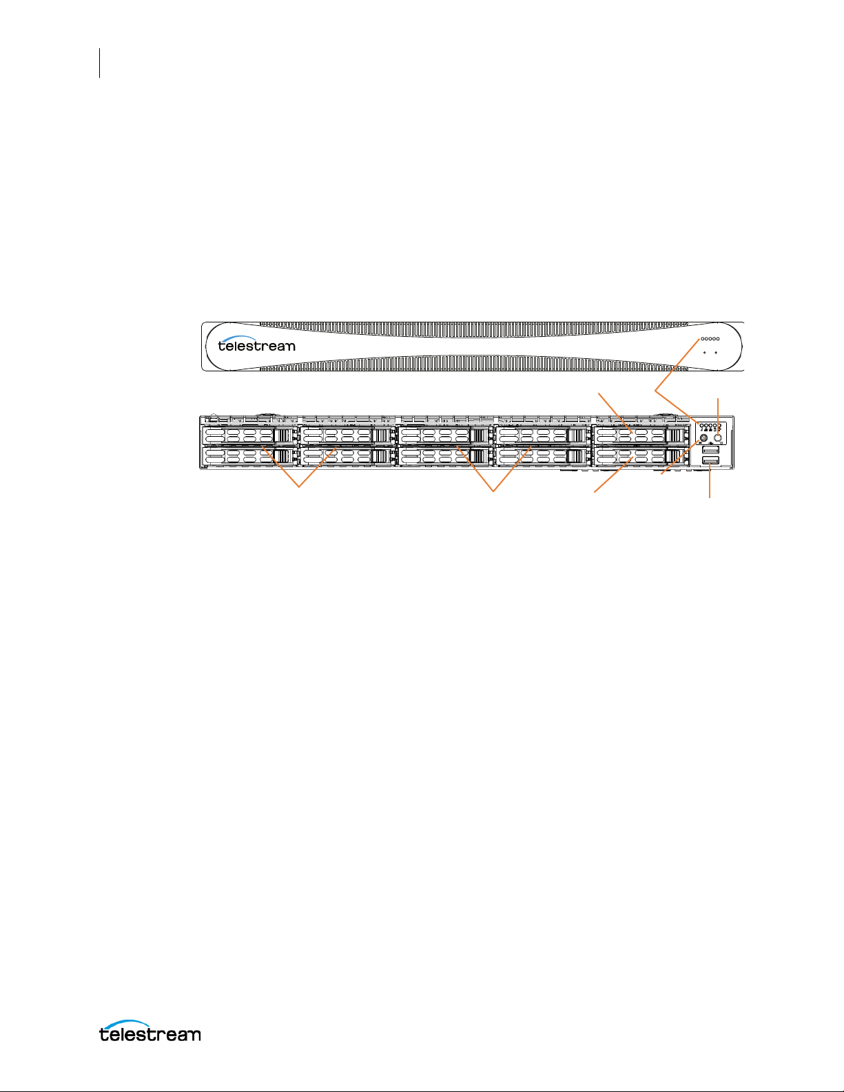
32
Lightspeed Live
LEDs On/Off Button
2 USB 3.0
SSD/SATA OS Drive
4 Included RAID 5
SAS Drives
4 RAID 5 SAS
Available Drive Bays
Available SSD or
SATA Drive Bay
UID Button
Introducing Lightspeed Live Stream and Capture
Lightspeed Live Server Hardware Specifications and Components
Front Panel
The Lightspeed Live server has a removable front bezel. By removing the bezel, you can
access the system interface buttons and LEDs, drives, and 2 front USB ports.
Front Panel Features
The removable front bezel provides visibility of the system monitoring LED indicators
and allows pinhole access to the recessed UID and power buttons.
Lightspeed Live Server Front Bezel:
LEDs (left to right)
• System Overheat | FAN Fail | UID
• Network Activity (NIC1)
• Network Activity (NIC2)
• Hard Drive Activity
• Power
UID Button (left)
The UID button alternately turns on and off the blue front and rear panel UID LEDs used
to locate a particular unit among many units in a rack or server room.
Power On/Off Button (right)
Press the Power On/Off button to perform a normal power up/power down cycle or a
hardware reboot (hold the button down for 4 seconds). A reboot abnormally
terminates connected clients and systems and should be done only in the event of an
unrecoverable system error. Under normal conditions, you should properly close client
programs and shut down the domain and OS before cycling power.
USB Ports
Two USB 3.0 ports for general use are located below the LEDs and buttons.
Lightspeed Live Capture User Guide
Page 33
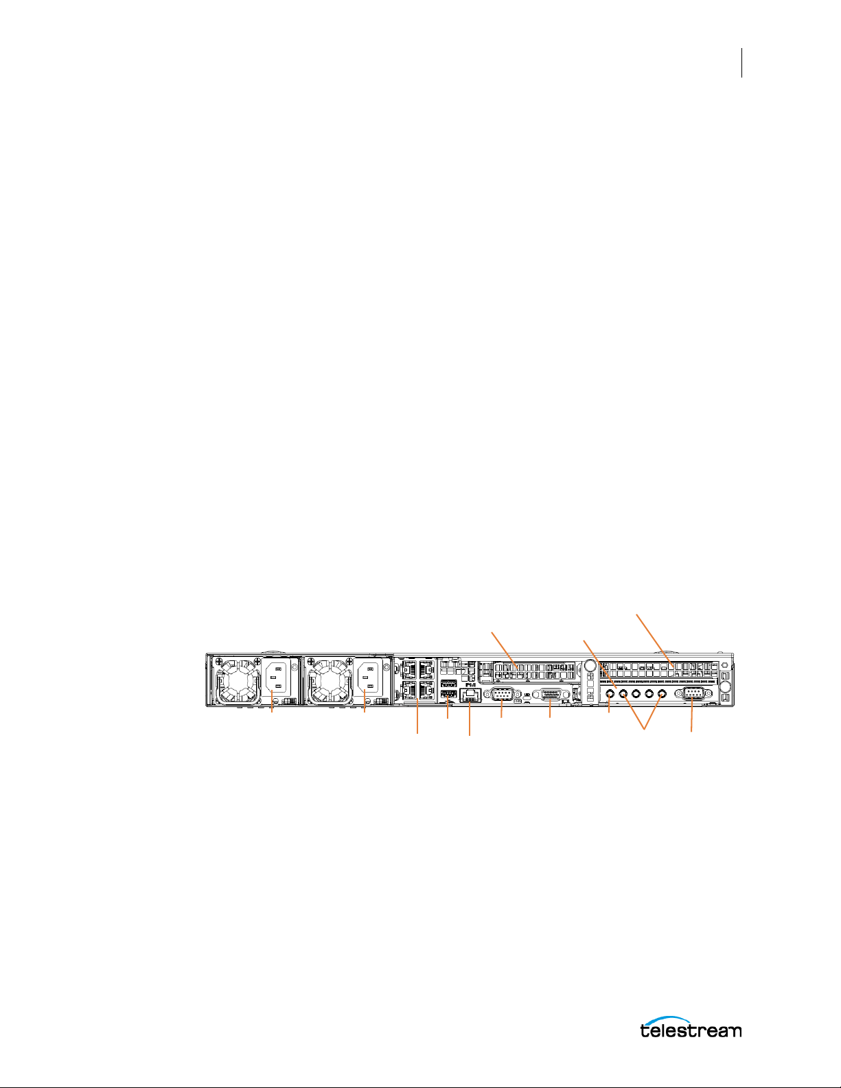
Drives
AC Power Connectors
1 PCI half height x8
expansion slot for
Telestream approved
cards only
4 Onboard 10GB
Ethernet LAN ports
IPMI port
(dedicated)
2 USB VGACOM
4 mini-BNC
SDI Inputs
Unused
LTC
SDI input Card
GPU Card
The top right-most drive bay houses the SSD/SATA Windows OS drive, and the drive
beneath it is an available SATA drive bay. These drives have their own controller,
separate from the storage drives.
To the left of the OS drive are 8 SAS media storage drive slots containing the 4 standard
and 4 optional media drives. These drives are configured for RAID 5 and have their own
controller separate from the OS drive.
Rear Panel
These are the rear panel ports and connectors:
Introducing Lightspeed Live Stream and Capture
Lightspeed Live Server Hardware Specifications and Components
• 2 redundant AC power connectors—connect to a 10-amp or greater AC source
• 4 10GbT Ethernet LAN ports—connect as required to Ethernet LAN
• 2 USB 3.0 ports—connect as required to keyboard, mouse, or other serial device
• 1 IPMI Ethernet dedicated port that should not used for any other purpose
33
• 1 VGA monitor port
• 1 COM control port (not used)
• 4 3G-SDI inputs
• 1 analog LTC input
Lightspeed Live server Rear Panel:
Additional PCI cards can be optionally installed by Telestream in the PCI expansion
slots.
Video Input Connections
Lightspeed Live Capture User Guide
The Lightspeed Live server includes an installed standard SDI input card (included) or
an optional HEVC SDI input card in the lower right PCI slot. For a complete list of video
formats, see the SDI Input Cards.
Page 34
34
Introducing Lightspeed Live Stream and Capture
Lightspeed Live Server Hardware Specifications and Components
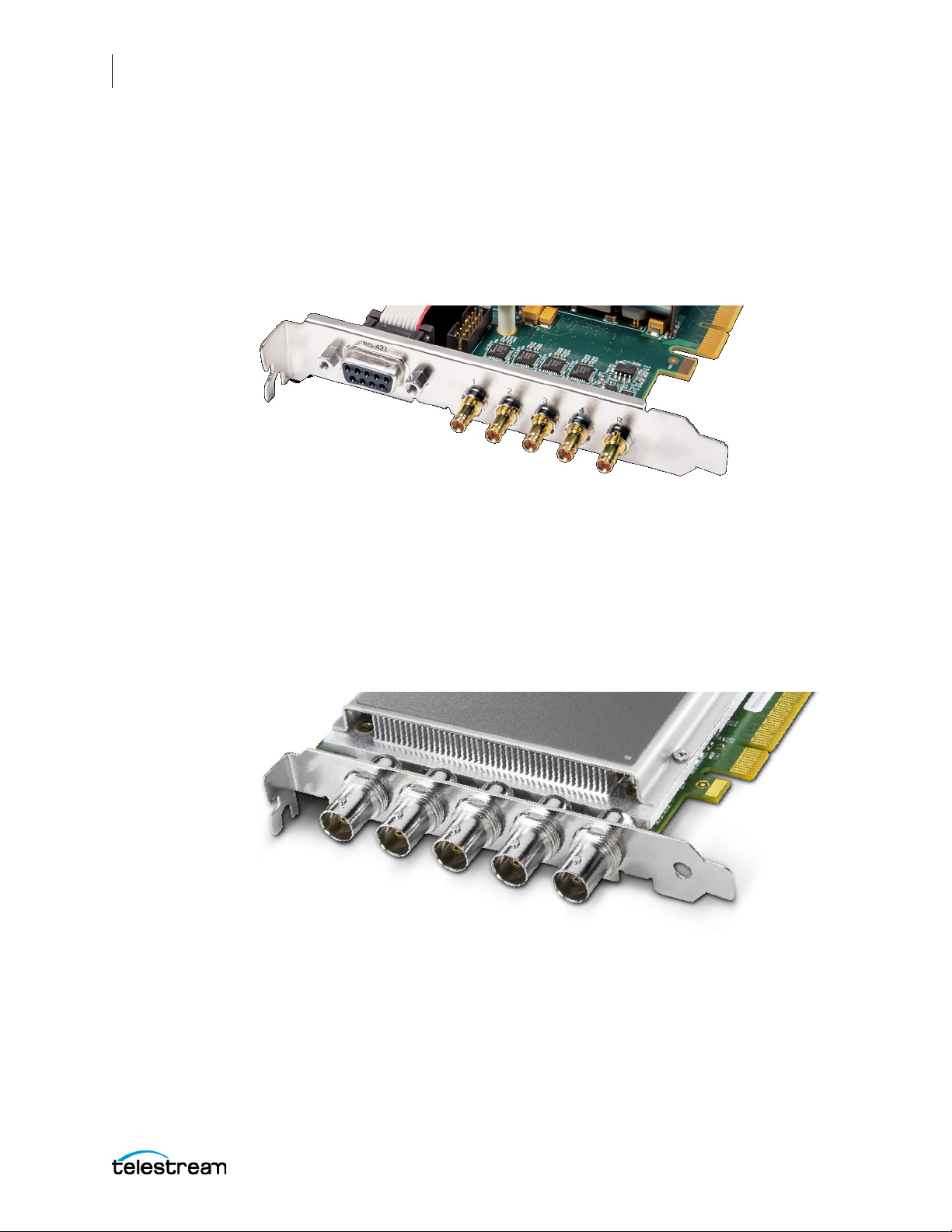
Standard SDI Input Card
The standard SDI input card contains 5 miniature BNC video input connectors with 5
adapter cables to convert to full-size BNC connectors:
• SDI Inputs 1-4: SD/HD/3G x 1080/4K video formats; audio 16-Channel, 24-bit SDI
embedded, 48 kHz synchronous
• Input R: LTC timecode input
Optional HEVC SDI Input Card (Supported by Live Stream only)
The HEVC card replaces the standard SDI input card and contains 5 full-sized BNC video
input connectors:
• SDI Inputs: SD/HD/3G x 1080/4K video formats; audio 16-Channel, 24-bit SDI
embedded, 48 kHz synchronous
• LTC T i mec od e I npu t: The BNC connector on the bottom of the board, on the far
right in the picture below:
Lightspeed Live Capture User Guide
Page 35

Installing and Maintaining the Server
This chapter explains how to install the Lightspeed Live server into an equipment rack
and configure it for operation.
■ Installing the Server
■ Making Connections
■ Managing the Operating System
■ Maintaining the Lightspeed Server
35
■ Monitoring Lightspeed Live via SNMP
Page 36

36
Installing and Maintaining the Server
Installing the Server
Installing the Server
■ Unpacking the Server
■ Installing the Optional USB Cable Retainer for the RS-422 VTR Control Interface
■ Rack Installation
WAR NING : Only trained and qualified personnel should be allowed to install, replace, or
service this equipment.
CAUTION: Except for replaceable power supplies and hard drives which may be
accessed from the outside, the Lightspeed Live server is a sealed device, with no userserviceable parts or user-accessible expansion slots. You should never open the top
cover or attempt to upgrade or alter the server. Doing so exposes you to electrical
hazard, may damage the unit, and may invalidate your warranty. If you have hardware
or software problems with your Lightspeed Live server, follow the steps in Appendix A:
Support of this guide to obtain service.
Note: Before proceeding, work with your network administrator to determine
computer and network setting requirements.
Unpacking the Server
The Lightspeed Live server arrives packed in a heavy duty cardboard box with foam
padding surrounding the device to protect it. During unpacking, inspect the container
and the contents for damage. If there is any damage, report it immediately to the
freight carrier and to TelestreamSupport.
The server is heavy. Unpack the server on a strong, well-balanced table that can
support the full weight of the server and shipping container without tipping.
Inside the box, you will find the server, optional components such as rack rails, five mini
BNC to standard BNC cables, and documentation on paper and flash drive (a DVD is
available by request).
Installing the Optional USB Cable Retainer for the RS-422
VTR Control Interface
When you will be using the USB to RS-422 Interface for VTR control, it is best to install
the USB Cable Retainer on the back of the Lightspeed Live server before installing the
server in the rack. For instructions, see Installing the USB Cable Retainer on the Lightspeed
Live Server in Appendix C.
Lightspeed Live Capture User Guide
Page 37
Rack Installation
The Lightspeed Live server is designed to fit into a standard 19-inch (483 mm)
equipment rack with support front and rear, using supplied rack rails and rear support
extensions.
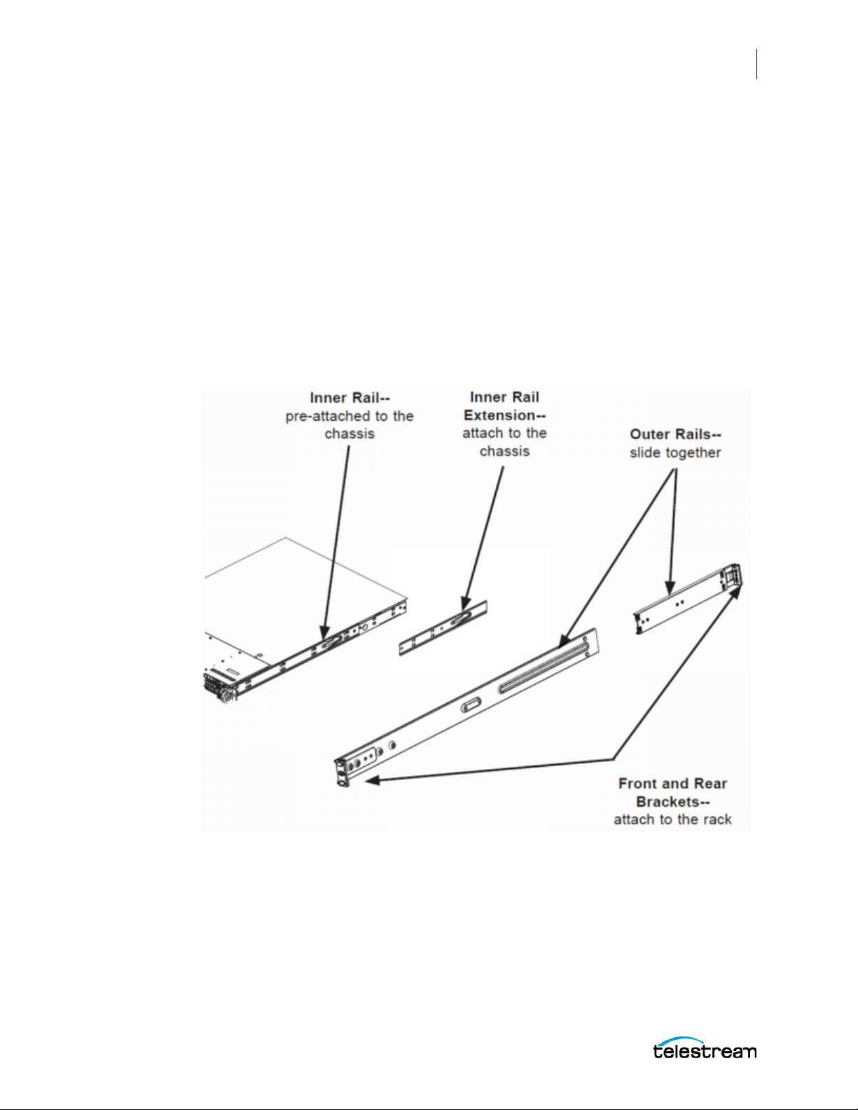
Assembling the Rails
The inner rail extensions install on each side of the chassis as shown. Align the
extension’s holes with the hooks on the side rail and slide the extension forward to
engage the hooks until the quick release bracket snaps into place. For added stability,
you can secure the extension with a screw.
The outer rails assemble by sliding the front and rear sections together as shown.
Installing and Maintaining the Server
Installing the Server
37
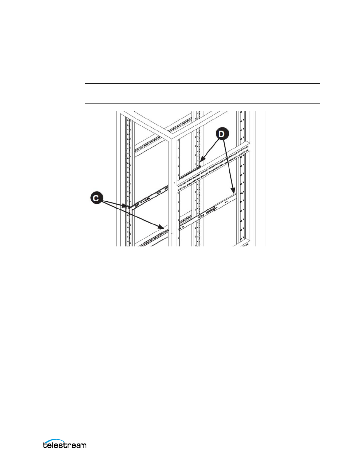
Installing Outer Rails into a Rack
Next, install the outer rails into the rack as shown in the next figure. Align the square
pegs on the front of the rail with the square holes in the front of the rack (C).
Push the rail into the rack until the quick release bracket snaps into place, securing the
rail to the rack.
Lightspeed Live Capture User Guide
Page 38
38
Installing and Maintaining the Server
Installing the Server
Extend the rear of the rail to align its square pegs with the square holes on the rear of
the rack (D). Push the rail into the rack until the quick release bracket snaps into place,
securing the rail to the rack.
CAUTION: To prevent the server chassis from falling and becoming damaged, be sure
the rails are solidly in position and ready to support the full weight of the chassis.
F
Installing the Server in the Rack
When selecting a position in a rack to place the server, be sure to allow a minimum of
30 inches of clearance at the back of the server for sufficient cooling airflow and
servicing.
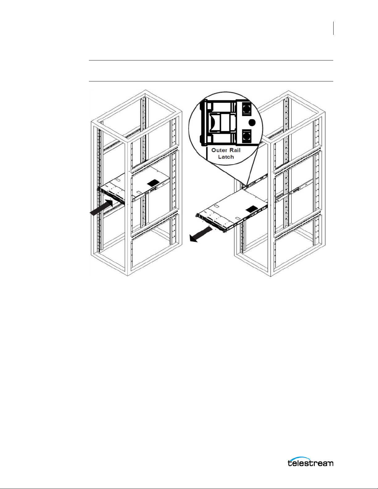
To install the server, follow this procedure:
Slide the inner rail extensions forward into the front of the outer rails.
Support the chassis and align the back of the chassis with the front of the rails.
Push the chassis backward, sliding it into the rack rails, until the chassis clicks into the
locked position.
Lightspeed Live Capture User Guide
Page 39
Installing and Maintaining the Server
Installing the Server
CAUTION: To prevent the server from falling and becoming damaged, be sure it is
securely in the rack before you remove support.
39
If you need to remove the server from the rack, press the outer rail latch shown in the
figure to release the chassis.
Slide the chassis forward off the outer rails and out of the chassis.
Lightspeed Live Capture User Guide
Page 40

40
AC Power Connectors
1 PCI half height x8
expansion slot for
Telestream approved
cards only
4 Onboard 10Gb
Ethernet LAN ports
IPMI port
(dedicated)
2 USB VGACOM
4 mini-BNC
SDI Inputs
Unused
LTC
SDI input Card
GPU Card
Installing and Maintaining the Server
Making Connections
Making Connections
This topic describes the server’s connectors and how to connect to them. Follow the
order of connections given here:
■ Data and Signal Connections
■ Power Requirements and Connections
Data and Signal Connections
Make the following data and signal connections at the back of the server unit:
• Make Ethernet LAN connections to provide network connectivity.
Note: The Lightspeed Live Stream server can generate large amounts of network
traffic when actively streaming. To prevent possible network issues, consult with your
IT administrator to determine the best network configuration for your environment.
• Connect devices, such as a keyboard and mouse, to the USB connectors (optional).
• Connect a dedicated IPMI LAN to the IPMI port (optional).
• Connect a monitor to the VGA connector (optional).
• Connect SDI video sources to the connectors on the SDI input card using the sup-
plied mini-to-BNC SDI cables.
• Connect an analog LTC timecode source to the BNC input connector marked with
an R (leftmost) on the SDI input card. This input is configured for an analog audio
signal containing Longitudinal Timecode (LTC) encoded with SMPTE timecode
data, as defined by SMPTE 12M.
Note: This input is for analog LTC only and is not intended for use as a sync
reference.
• Connect the optional 4-Port RS422 VTR Interface Kit to a USB port. See Appendix C:
RS-422 VTR Interface.
Lightspeed Live Server Rear Panel:
Lightspeed Live Capture User Guide
Page 41

Power Requirements and Connections
After the server chassis has been physically installed and all other connections made,
connect the two redundant AC power cords to the back of the chassis and to an AC
power source. Be certain to observe the following AC power and connection
requirements and all applicable electrical codes.
The Lightspeed Live server is rated at 100-240 VAC, 50-60 Hz, up to 10 amps. Take the
following precautions to ensure a safe power connection:
• Make certain that the power source circuit can supply voltage within the specified
range and current of at least 10 amps without becoming overloaded.
• Counted together, the server and other devices connected to the same power
source must not exceed the total capacity of the power source circuit.
• To protect against circuit overload and overheating, ensure that the power source
circuit includes a circuit breaker no greater than 250 Volts, 20 Amps.
When power is connected, press the Power On/Off (0/1) button on the front of the
chassis to turn the server on. To turn power off at any time, press the Power On/Off
button again.
Installing and Maintaining the Server
Making Connections
41
Power and General Cautions and Warnings
Observe the following precautions when connecting power and operating the server.
WAR NING : Only trained and qualified personnel should be allowed to install, replace, or
service this equipment.
WAR NING : Hazardous voltage or energy is present on the backplane when the system is
operating. To prevent possible injury or death, use caution when servicing.
WAR NING : This product relies on the building's installation for short-circuit (over-current)
protection. Ensure that the protective device is rated not greater than 250 Volts, 20 Amps.
WAR NING : Ensure a proper earth ground connection to the ground conductor in the AC
power plug. Failure to do so could present a severe electric shock hazard that could result
in injury or death.
CAUTION: Telestream recommends connecting computer equipment to AC power
through an uninterruptible power supply (UPS) with surge protection. Fluctuations in
commercial supply voltage can damage unprotected electronic equipment. A high
quality surge suppressor may be substituted if a UPS is not available, but it may not
provide adequate electrical spike protection.
Lightspeed Live Capture User Guide
Page 42

42
Installing and Maintaining the Server
Making Connections
WAR NING : When installing the product, use the provided or designated connection
power cables. Using any other cables could cause a malfunction or a fire.
WAR NING : The fans might still be turning when you remove the replaceable power
supply from the chassis. Keep fingers, screwdrivers, and other objects away from the
openings in the replaceable power supply’s housing.
WAR NING : Power supplies and other components can get very hot. Use caution when
touching possibly hot components during operation and directly after unplugging.
WAR NING : This unit has two power supply connections. Both connections must be
removed to completely de-energize the unit.
Installing the Optional RS422 VTR Interface Kit
For complete instructions on installing the RS422 VTR Interface Kit, see Appendix C: RS-
422 VTR Interface.
Lightspeed Live Capture User Guide
Page 43

Managing the Operating System
Windows Server 2012 R2 (Standard 64-bit) is pre-installed on the Lightspeed Live server
on an SSD drive. See microsoft.com
supported for Live Stream 3.0, and is available by request.
Microsoft Activation Key
A sticker on the top surface of the Lightspeed Live server lists license numbers. The
number listed as the Physical Key is the OEM license number for the Microsoft Windows
operating system. If you remove and reinstall the OS, you will need to use this key to
activate Windows again. The number typically contains five groups of five digits, as in
this example: YFG8H-TDD97-6BR4G-F88PF-XXXXX.
Microsoft Updates
The Lightspeed Live server ships with the Windows operating system set to check for
updates, but it does not automatically download or install them. Downloading and
installation of critical operating system updates is the responsibility of each customer
(see your system administrator).
for OS specifications. Windows Server 2016 is also
Installing and Maintaining the Server
Managing the Operating System
43
Windows User ID and Password
After the Lightspeed Live server boots up, you can log into it with the following
Windows user account.
:
Lightspeed Server Windows User Account
User Administrator
Password telestream!1
Windows Firewall
The Lightspeed Live Capture web application uses port 8083 and/or 8084, and Live
Stream uses port 8089. If you use Windows Firewall, be sure those ports are open on the
Lightspeed Live server and across your network.
To open the Windows firewall on the Lightspeed Live server or other Windows
machines, go to Start > Control Panel > Windows Firewall > Allow a program or feature
through Windows Firewall > Allow another program.
Scroll through the list of programs, and click Add for each of these: Lightspeed Live
Capture, Lightspeed Live Stream, Vantage Management Console, and Vantage
Workflow Portal.
Click OK to close the programs list. The added programs appear in the firewall list, and
you can check which networks they can use. Then close the Control Panel.
Lightspeed Live Capture User Guide
Page 44
44
Installing and Maintaining the Server
Maintaining the Lightspeed Server
Maintaining the Lightspeed Server
The following section describes common server maintenance tasks that you may need
to perform from time to time:
■ Performance Tuning a Lightspeed Live Server
■ Backing up the Lightspeed Live Server
■ Managing the Lightspeed Live Server
■ Installing New or Replacement Hard Drives
■ Rebuilding the Lightspeed Live Storage RAID
■ Replacing Power Supplies
■ Monitoring Lightspeed Live via SNMP
Performance Tuning a Lightspeed Live Server
The following settings are made at the factory to ensure best performance of your
Lightspeed Live server. The settings are supplied here in the event they have been
changed and you need to restore them to factory original settings. (For details, consult
your System Administrator or a Telestream Field Sales Engineer).
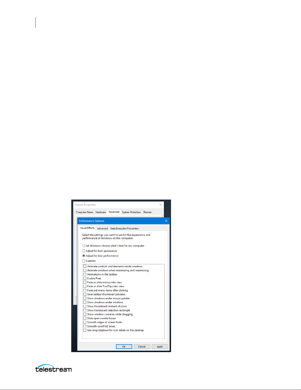
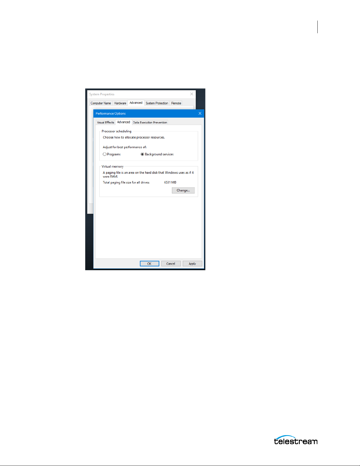
1. In Performance Options, set Windows Performance options:
a. Navigate to Start > Control Panel > System > Advanced system settings >
Settings button > Visual Effects tab.
b. Select Adjust for best performance.
Lightspeed Live Capture User Guide
Page 45
Installing and Maintaining the Server
Maintaining the Lightspeed Server
c. Select the Advanced tab.
d. Select Background services for Vantage transcoding nodes and SQL nodes. Select
Programs for editorial systems and Vantage client applications that are not
running other Vantage services.
45
Lightspeed Live Capture User Guide
Page 46
46
Installing and Maintaining the Server
Maintaining the Lightspeed Server
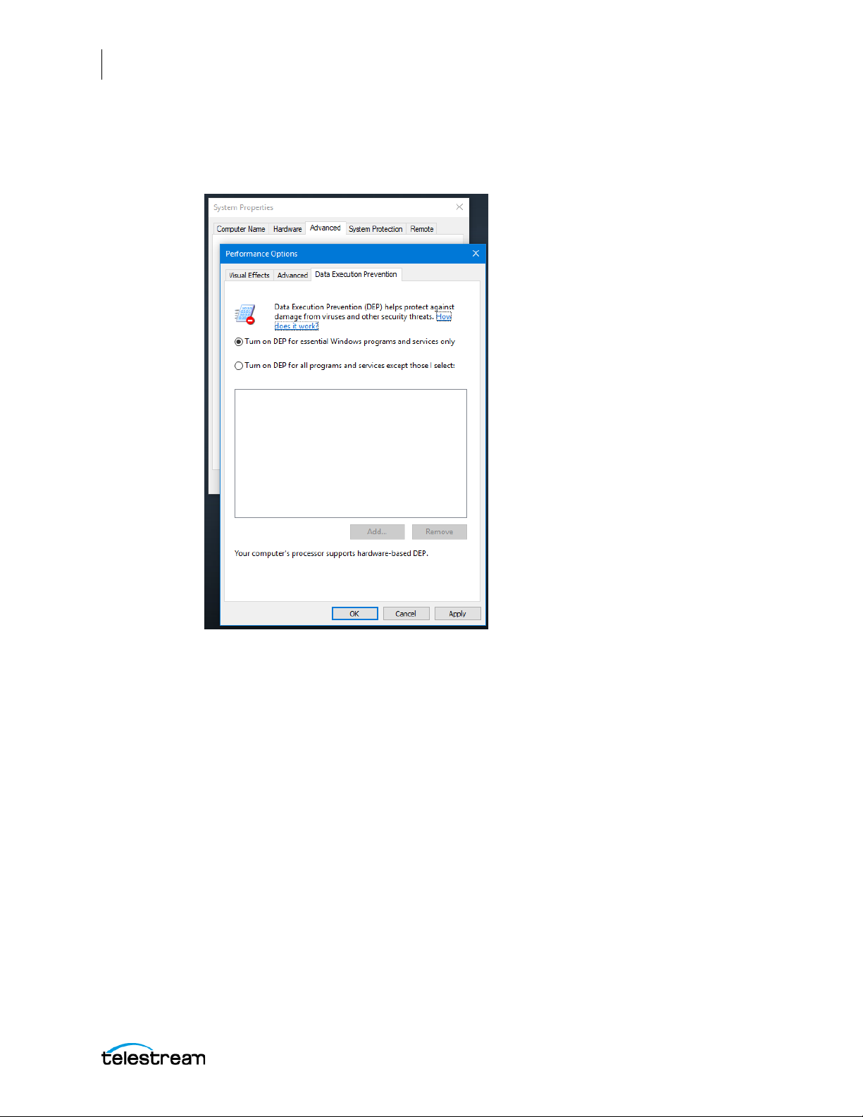
e. Select the Data Execution Prevention tab:
f. Select Turn on D EP (Data Execution Prevention) for essential Windows programs and
services only.
g. Click OK in both dialogs to save your changes.
2. Set User Account Control (UAC):
a. Navigate to Start > Control Panel > User Accounts > Change User Account
Control Settings. Set as low as safely possible, considering your exposure to
Internet viruses and malware. Click OK to save your changes.
3. Set Power Options to High Performance with Sleep disabled:
a. Navigate to Start > Control Panel > Power Options.
b. Select the High Performance plan.
c. Select Change plan settings, and set Turn off the display to Never.
d. Select Change advanced power settings, and set all critical functions so that they
are always ON (this usually means setting them to Never turn OFF). Click OK to
save your changes and close the dialog.
e. Click the Save Changes button on the Edit Plan Settings window.
Lightspeed Live Capture User Guide
Page 47

Installing and Maintaining the Server
Maintaining the Lightspeed Server
4. Disable (turn OFF) any real-time software applications and processes, such as the
following, that could adversely affect disk I/O performance or use excessive CPU:
– Real-time virus scanning of media files as they are being captured.
– Automatic software updates that can preempt real-time services.
– Real-time file indexing.
5. Disable all unnecessary Windows services in Start > Control Panel > Administrative
Tools > Services (consult your System Administrator).
6. Turn OFF all firewalls (including third party firewalls) and packet filtering, which may
cause unpredictable performance:
a. Navigate to Start > Control Panel > Windows Firewall > Turn Windows Firewall on
or off, select Turn off Windows Firewall.
If you choose to use firewalls, open them for the applications installed on the Lightspeed Live server.
7. You may increase network throughput by increasing buffer size within your
network adapter. Set your Network Adapter’s transmit and receive buffers to 1024:
a. Navigate to Start > Control Panel > Network and Sharing Center > Change
Adapter Settings > Local Area Connection > Right-click and select Properties.
8. Disable any screen savers:
47
a. Navigate to Start > Control Panel > Personalization > Screen Saver and select
(None).
9. Disable disk indexing:
a. Right click on Start and select Disk Management from the pop-up menu.
b. Right-click each disk and select Properties.
c. In the General tab uncheck Allow files on this drive to have contents indexed in
addition to file properties, unless you want some drives to be indexed.
Backing up the Lightspeed Live Server
In order to protect your Lightspeed Live server from data loss, Telestream highly
recommends that you create an image of the Operating System drive (C:\) drive
immediately upon taking delivery of your server and that you perform periodic backups of all critical data on the server.
Several disk image software solutions are available for creating a restoration image that
you can use to restore the Lightspeed Live server's operating system drive (C:\) to its
original state. Using software solutions such as these, along with regular backups, you
can restore your server back to its original shipping state with all of your critical data:
• Norton Ghost
• Clonezilla
Consult your IT/Systems administrator for details on creating restoration images and
performing a periodic backup of your Lightspeed’s critical data.
Lightspeed Live Capture User Guide
Page 48

48
Installing and Maintaining the Server
Maintaining the Lightspeed Server
Managing the Lightspeed Live Server
IPMI View management software provides remote network management of one or
more Lightspeed or Lightspeed Live servers using IPMI messages over Ethernet LAN or
a dedicated IPMI LAN. If your Lightspeed Ethernet connectors are used to connect to
storage, you can use the IPMI LAN connector to create an IPMI network among your
Lightspeed servers.
To download IPMI View, paste this expression into your browser and press Enter:
ftp://ftp.supermicro.com/utility/IPMIView/.
You’ll find the IPMI View User’s Guide at this browser location:
ftp://ftp.supermicro.com/utility/IPMIView/IPMIView20.pdf
Among the tasks you can perform using IPMI View are these (see the IPMI View User’s
Guide for details):
• Discover Lightspeed Servers on the IPMI network (requires dedicated IPMI LAN)
• View system event logs
• Check current sensors and monitor history of fans, voltages, temperature, and
power supplies
• View firmware revision levels
• Perform various kinds of shutdowns and resets
• Blink the UID LED to locate a particular unit in the rack or server room
• Set fan speed
• Manage LAN configuration, SNMP configuration, and RS232 modem
• Manage users, passwords, and privileges
• Set up paging of users in the event of malfunctions
• Establish Text Console Redirection or KVM Console Video Redirection for remote
system control via text display or full graphic display
• Access virtual media
• Set up server management groups
• Update firmware
For detailed instructions about using any of these system management features,
consult the IPMI View User’s Guide.
Lightspeed Live Capture User Guide
Page 49

Installing New or Replacement Hard Drives
Follow these steps to replace a failing hard drive or install a new one. Drives may be
removed or replaced with power on. See Drives for new or replacement drive
specifications.
1. Remove the front bezel from the chassis.
2. Press the release button on the right front of the drive carrier.
3. Use the drive carrier handle to pull the carrier out of the chassis.
Installing and Maintaining the Server
Maintaining the Lightspeed Server
49
4. Remove the drive or dummy drive from the carrier by removing the four M3 screws
from the underside of the carrier. Retain the screws.
5. Insert the new drive into the carrier with the PCB side down and the connector
facing the back of the carrier.
6. Secure the drive to the carrier with the four M3 screws retained from removal.
Gently tighten but do not over tighten the screws, which could cause damage.
7. Slide the drive carrier into its bay with the drive facing up until the drive seats firmly
in the rear connector.
8. Push the carrier handle closed flat against the front of the carrier to secure the
carrier and drive in place.
9. Replace the front bezel on the chassis, and go to the next topic to rebuild the RAID.
Lightspeed Live Capture User Guide
Page 50
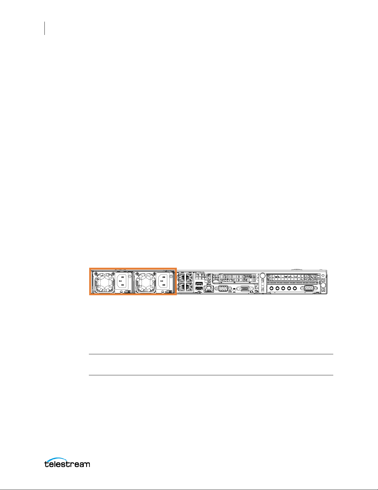
50
Installing and Maintaining the Server
Maintaining the Lightspeed Server
Rebuilding the Lightspeed Live Storage RAID
The MegaRAID Storage Manager software on the Lightspeed Live server enables you to
rebuild the storage RAID if necessary, such as when you add a new drive, or want to
change drive configurations. The MegaRAID Storage Manager is located at:
C:\Program Files (x86)\MegaRAID Storage Manager
In the MegaRAID Storage Manager folder, locate the startupui.bat file and doubleclick it to start the application. In the initial application panel, click on the server you
want to work with, then enter your credentials to log in. The MegaRAID Storage
Manager application opens.
Replacing Power Supplies
The Lightspeed Live server includes two redundant, hot-pluggable power supply
modules. They automatically sense the input voltage between 100v to 240v, and
operate at that voltage. Power cords plug directly into the power supply units at the
back of the chassis. A green light indicates that the power supply is operating. When a
power supply fails or loses power, an amber light on the power supply illuminates and
an alarm sounds.
If either of the power supply modules fail, the other module will support the full load
and will allow the system to continue operation without interruption. The PWR Fail LED
will illuminate and remain on until the failed unit has been replaced. Replace with the
same model. Replacement units can be ordered from Telestream. See Appendix A:
Support in this guide for information about contacting Telestream Support to order parts.
Replacing the Power Supply
1. Unplug the AC power cord from the failed power supply module.
2. Push in the locking tab at the back of the module to release it.
3. Pull the unit straight out of the chassis.
CAUTION: The power supply may be very hot when first unplugged and could cause
burns. Handle carefully by the edges and do not touch hot components.
4. Insert the new unit into the chassis, pushing it in until it clicks firmly in place.
5. Reconnect the power cord.
Lightspeed Live Capture User Guide
Page 51

Installing and Maintaining the Server
Monitoring Lightspeed Live via SNMP
Management Information Base (MIB) files are provided for those organizations wanting
to manage their Lightspeed Live servers via SNMP.
MIB files can be found on the Lightspeed Live server in this location:
C:\Program Files\Telestream\Live Stream Server
MIB files can also be found on the Lightspeed Live DVD or USB thumb-drive in the
SNMP folder.
Enabling SNMP Monitoring
The user needs to add three lines to the SourceService.exe.config and
LiveService.exe.config files in order to enable SNMP traps and configure ports. For more
information about log files see Using Log Files and Other Support Information in
Appendix A.
51
Monitoring Lightspeed Live via SNMP
Note: The ports need to be different in each configuration file and a value of 162
should not be used.
The following example shows a typical configuration file. The lines in red are the ones
that need to be added to the existing configuration files by the user:
<nlog xmlns="http://www.nlog-project.org/schemas/NLog.xsd"
xmlns:xsi="http://www.w3.org/2001/XMLSchema-instance">
<extensions>
<add assembly="NLog.Targets.Snmp" />
</extensions>
<targets>
<target name="logconsole" xsi:type="Console" layout="[${level}]
${message}" />
<target name="logfile" xsi:type="File" archiveAboveSize="10000000"
maxArchiveFiles="1000"
fileName="${specialfolder:folder=ApplicationData}/Live/SNMPLogs/
LiveService-${date:format=yyyy-MM-dd}-log.txt" layout="${longdate}
[${level}] ${message}" />
<target name="snmp" xsi:type="Snmp" port="163" />
</targets>
<rules>
<logger name="*" minlevel="Info" writeTo="logconsole" />
<logger name="*" minlevel="Warn" writeTo="logfile" />
<logger name="*" minlevel="Info" writeTo="snmp" />
</rules>
</nlog>
Lightspeed Live Capture User Guide
Page 52

52
Installing and Maintaining the Server
Monitoring Lightspeed Live via SNMP
Lightspeed Live Capture User Guide
Page 53

Configuring the Lightspeed Live Capture Server and Apps
This chapter explains how to configure and maintain the Lightspeed Live Capture
software, including implementing updates.
These topics will help you configure and maintain the server:
■ Changing a Source Name
■ Managing and Configuring Sources
■ Configuring Capture Resources
53
■ Configuring Settings for Your Facility
■ Using Inputs for Both Live Stream and Capture
■ Configuring Ingest Sources
■ Installing the Live Capture & Tape Capture Web Apps
■ Renaming or Reconfiguring Servers
■ Updating Capture using Secured Version Control and ComponentPacs
■ Clear Browsing Data after Updating Vantage or Live Capture
Page 54

54
Configuring the Lightspeed Live Capture Server and Apps
Changing a Source Name
Changing a Source Name
The default names for SDI ports has this form: “SDI Input [1 through n]”, where ‘n’ is 4 or
8 depending on which Lightspeed Live server you have. To rename a source, follow the
procedures below and observe these renaming rules:
• The Source Manager can be used to change the input source's name. After chang-
ing a source name you must edit affected Capture actions and select the rena
sour
ce. You can determine which workflows use a particular input source by usin
nd Workflows... from the Capture Inventory panel in the Vantage Manage
Fi
Console.
• Each source must be named uniquely.
• None of these characters can be used in the source name: ` * | \ : ; " ' < > ? /
med
g
ment
Lightspeed Live Capture User Guide
Page 55

Configuring the Lightspeed Live Capture Server and Apps
Managing and Configuring Sources
Note: The process of managing and configuring input sources for Live Capture has
changed in v3.0 (and later). All source management and configuration should now be
done from the Source Manager page (see below for details). The Capture Inventory
panel within the Vantage Management Console should be used for discovering
Workflows and Previewing the Inputs only.
Before capture video sources can be used, they need to be configured using the Source
Manager web app located at http://localhost:8090/ or http://[hostname]:8090/.
Up to four SDI streaming video sources, such as those from live cameras, can be connected
through the SDI Input connectors on the back panel of the Lightspeed Live Server. You can
also add IP-based RTMP and Transport Streams from your Ethernet connection.
Sources display the current input or the LOS Video Test Pattern that is selected in the
Configure Source dialog if there is no input. SDI inputs can be combined to make a
single 4K input. You can edit SDI sources but not delete them. They update when you
change the SDI input source. For supported formats see SDI Card Input Formats.
55
Managing and Configuring Sources
When there are multiple Lightspeed Live servers, the list of Sources in the Live Stream web
app is separated into a panel for each server, and each panel can be expanded and collapsed.
These are the source configuration topics covered here:
■ Sources Overview
■ Configuring an SDI Source
■ Configuring a File Loop Source
■ Configuring a Transport Stream Source
■ Configuring an RTMP Source
■ Managing and Configuring Audio Tracks
Note: Sources cannot be edited when they are being used by an active Channel.
Lightspeed Live Capture User Guide
Page 56
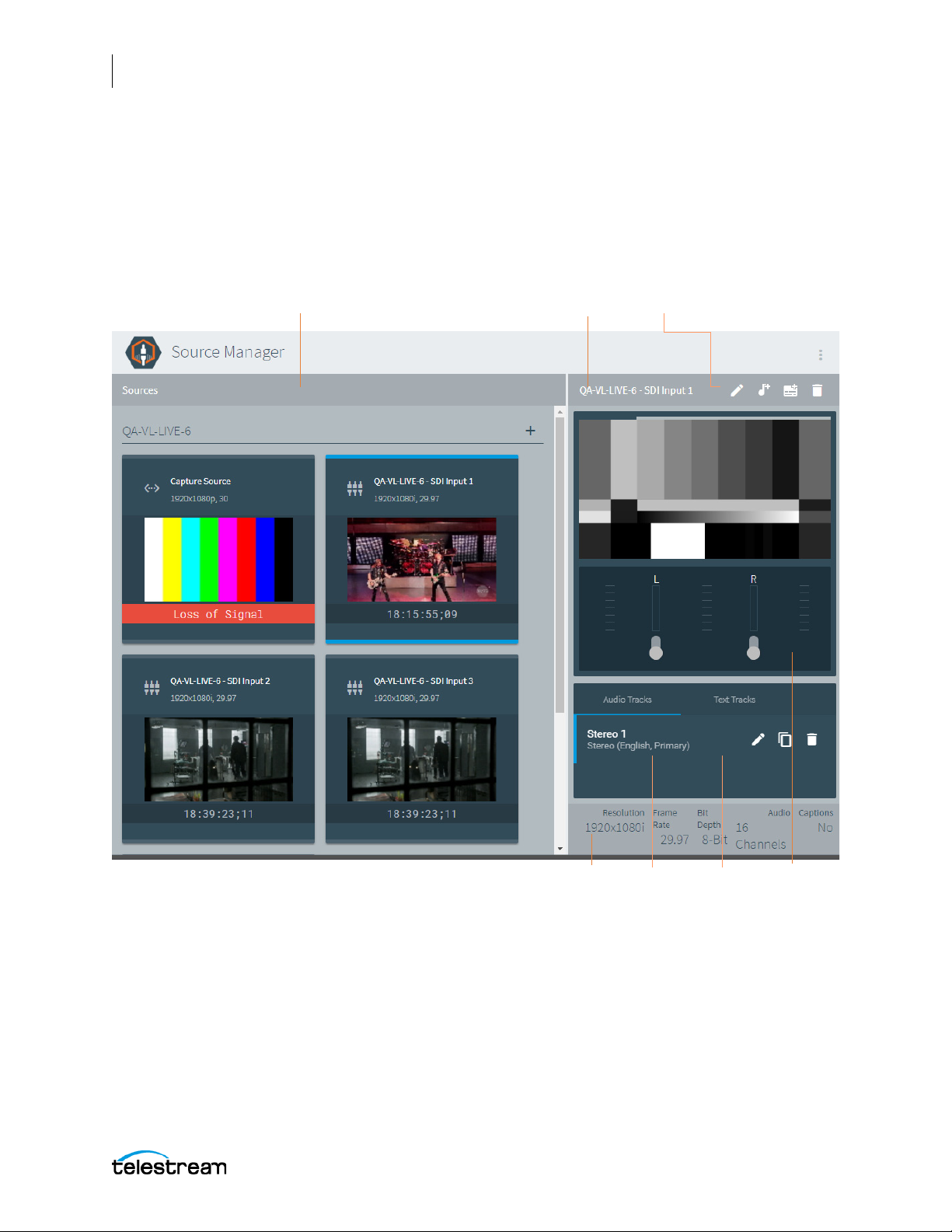
56
Source Information
and Statistics
Audio Levels
Sources Panel
Source Menu
Audio and Text
Track Panels
Source Preview Panel
Configuring the Lightspeed Live Capture Server and Apps
Managing and Configuring Sources
Sources Overview
The Sources panel displays when you access the Source Manager web app by entering
http://localhost:8090/ or http://[hostname]:8090/ in the your browser.
The Sources panel is organized into two panels: The left panel is the Sources list, which
displays the four built-in SDI sources, plus sources you’ve created. The right panel
displays a live preview feed of the selected source, along with track information.
• Sources Panel—Displays all source thumbnails, and allows you to select a source
t
o view or edit. See Source and Channel Indicator Icons.
• Add Source—Click the + icon in the Sources panel to add a new File Loop, Slate,
Transport Stream or RTMP source. The SDI input sources are automati
and y
ou can’t delete
them.
cally included
Lightspeed Live Capture User Guide
Page 57
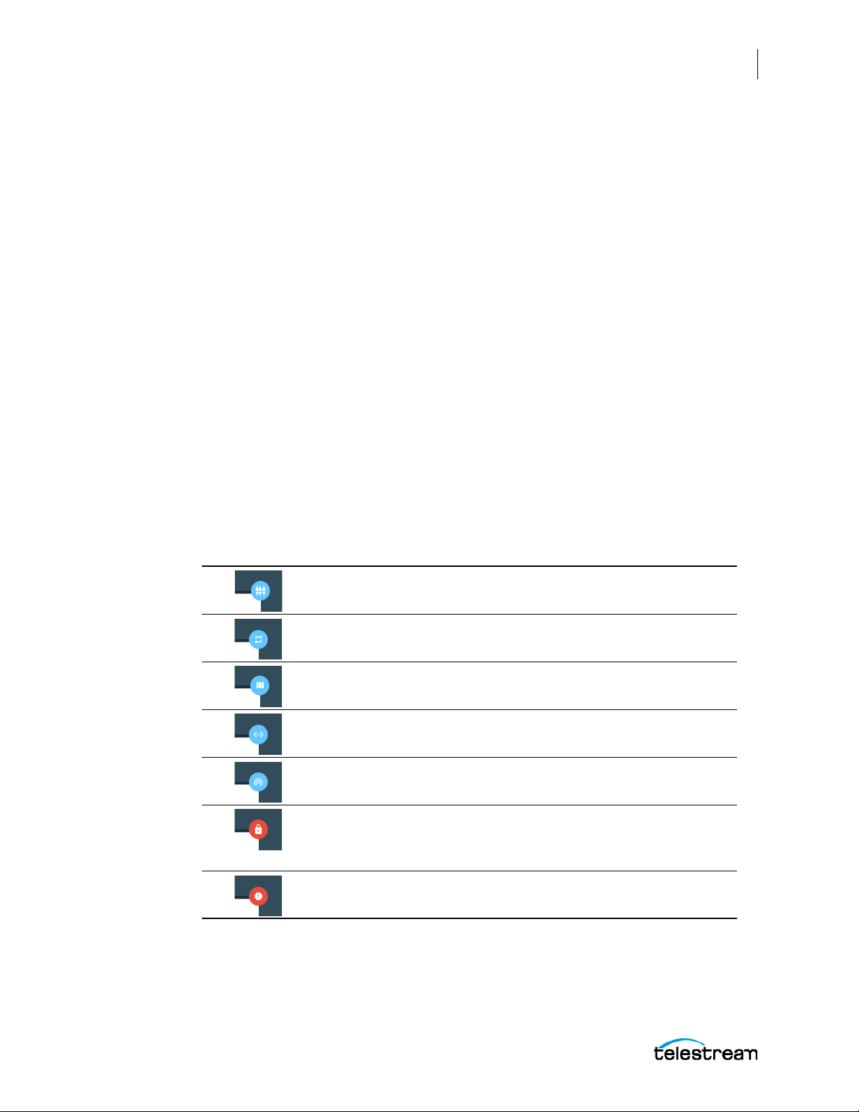
Configuring the Lightspeed Live Capture Server and Apps
Managing and Configuring Sources
• Source Menu Toolbar—top-right, above the Sources Preview Panel.
– Editor Icon—Click the pencil icon to view or update the settings of the selected
S
ource. Source configuration panels vary by type.
– Audio Track—Selects which audio track to configure and play. The Source
Preview panel shows the selected track.
– Text Track—(Live Stream only) Selects which caption track to use, 608 or 708.
The Source Preview panel shows the selected track.
– Delete Icon—Click the trash icon to delete the selected Source.
• Source Preview Panel—Displays the currently selected Source and audio meters.
• Source Information Panel—Displays details about the selected source video.
• Audio and Text Track Panels—Add, delete, and configure audio and captioning
ext tracks. Text Track is for Live Stream only.
t
• Audio Level Meters and Mute Controls—Audio level meters for each channel
that ad
channel-by-channel mute control. If you have multiple audio tracks, you ca
among them, u
just automatically, based on the track (stereo, 5.1 Surround Sound, etc.), with
n switch
sing the Audio Track menu
.
57
Source and Channel Indicator Icons
Icons in the thumbnail previews for each source in the Sources panel indicate the type
of source, whether that source is being used in a live stream, or if there is a loss of signal.
SDI source
File Loop source
Slate source
Transport Stream source
RTMP source
This source is currently being used in a stream and cannot be
edited or removed
This source has experienced a loss of signal
Lightspeed Live Capture User Guide
Page 58
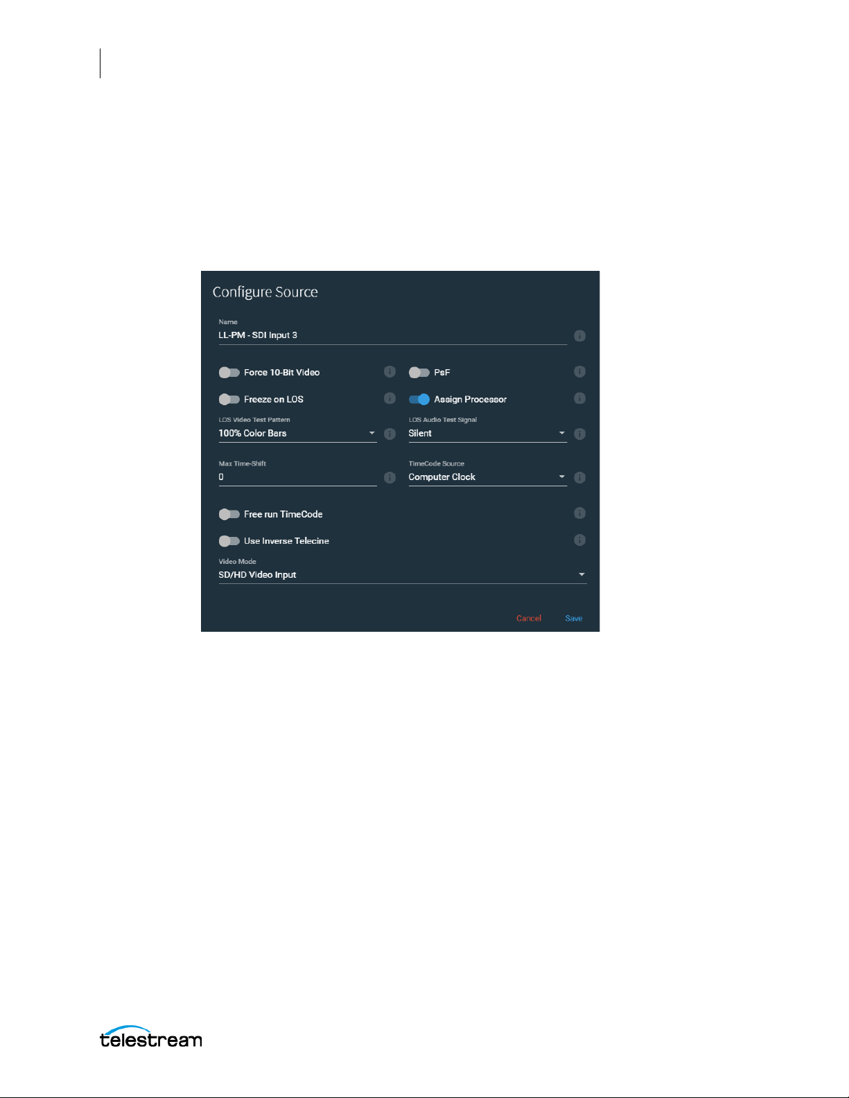
58
Configuring the Lightspeed Live Capture Server and Apps
Managing and Configuring Sources
Configuring an SDI Source
SDI Input source options are configured in the Live Source Manager web page. All SDI
sources present on Lightspeed Live systems are automatically added to the inventory
list of sources. For systems that have more than one Live Capture server in a domain
you will need to name each server’s SDI ports with unique names.
The SDI Configure Source dialog opens when you edit an SDI source.
Lightspeed Live Capture User Guide
Page 59

Configuring the Lightspeed Live Capture Server and Apps
Managing and Configuring Sources
The Configure Source dialog provides these options for the SDI input sources:
• Name—Specifies the name of the source.
• Force 10-Bit Video—When enabled, activates full 10-bit sampling of the video on
the SDI input. Using 10-bi
be enabl
CAUTION: When using an 8-bit leader, filler, or trailer along with the video, do not
enable the 10-bit sampling mode. Corrupted output can result.
ed for Standard Definition (SD) sources.
t sampling requires additional processing and should
• PsF—Enable PsF when your incoming SDI source signal is formatted as PsF (Pro-
gressive segmented Fr
Note: The Live Capture system always treats SDI sources with 23.98 fps or 24 fps as
progressive.
ame).
• Freeze on LOS—When enabled, a loss of signal (LOS) causes the incoming video
nal to freeze on the last frame. When disabled, LOS causes the LOS Video Te
sig
P
attern to be displayed. For LOS details, see Loss of Signal Behavior in the Lightspe
e Capture user guide.
Liv
59
not
st
ed
• Assign Processor (SD/HD sources only)—When enabled, all processing associ-
ated with individual Capture or Tape workflows is assigned to a single multi-core
CPU socket. If four (4) workflows are capturing concurrently, each workflow proc
s exclusively on a single CPU socket, with two (2) workflows on socket 1 and tw
run
orkflows on socket 2. This prevents inefficient mapping of processes across
(2) w
CPU sockets during heavy loads, such as when all four inputs are being processed.
Not enabling this option when capturing multiple workflow channels can re
ex
cessive CPU usage.
Note: This option defaults to ON (enabled) when capturing new non-4K SDI sources.
It should be disabled when capturing UHD/4K.
ess
sult in
• LOS Video Test Pattern—Select the test pattern to display when there is a LOS.
• LOS Audio Test Signal—Select the audio signal to use when there is a LOS.
• Max Time-Shift—This value represents the maximum size of the Time-Shift frame-
buffer (in seconds) for workflows using this SDI source. The recommended va
30 s
econds, or less, and is limited to no more than 60 seconds.
Note: Time-Shift—Live Capture’s Time-Shift allows you to hold incoming source
media frames in an internal FIFO buffer. You can choose to buffer up to 60 seconds of
media for each input on your Lightspeed Live server (some limitations may exist for
higher bit rates and frame rates). Caution should be taken when setting Time-Shift to a
value greater than 30 seconds on more than one input source. See Determining the
Time-Shift Buffer Duration for recommendations on settings for various frame sizes
and frame rates. When a capture workflow is activated with Time-Shift enabled, the
input’s source media is stored in a FIFO buffer which allows Lightspeed Live to reach
lue is
o
Lightspeed Live Capture User Guide
Page 60

60
Configuring the Lightspeed Live Capture Server and Apps
Managing and Configuring Sources
back in time and access media processed in the past based on the value of the TimeShift field. Since Live Capture’s Time-Shift is always processing an input source’s media,
when a record is initiated any media stored in the Time-Shift buffer is available to be
added to the captured file.
• TimeCode Source—Click the drop-down menu to choose one of the following
timecode source signals for the selected SDI input:
– Source—Uses the timecode provided in VBI or VANC (SMPTE 12M-2/RP188) of
the selected Lightspeed Live Capture's video input signal. If a valid timecode is
not available or goes away, see the Free Run TimeCode option below.
– Computer Clock—Uses the time-of-day clock provided by the Lightspeed Live
Capture Server.
– Free Run—This timecode starts at 00:00:00:00 and free-runs after the Capture
workflow associated with it is activated. The recorded timecode captured will
reflect the free run timecode at the time capture begins.
– Analog LTC—Uses the timecode provided on the SDI card's LTC input (marked
with an R on the SDI card). If a valid timecode is not available or goes away, see
the Free Run TimeCode option below.
– RS-422—Uses the timecode provided by a VTR connected via RS-422. (Requires
the optional RS-422 control kit.) If an input is connected to a VTR under RS-422
control, RS-422 must be selected for TimeCode Source.
Note: When using the Schedule Trigger you should set your TimeCode Source to
either Computer Clock or Source. When using Source, you must have time-of-day
timecode in your source that matches the time set in your Lightspeed Live server. See
Trigger Settings.
• Free Run TimeCode—When enabled, and the desired timecode is not detected or
goes away, the timecode will seamlessly free-run from the last good timecode
received. When Free Run TimeCode is not enabled, and the desired timecode is not
detected or goes away, then the timecode will revert to zero (00:00:00:00) and stay
at zero.
• Raw Ancillary Dump—Only available when Advanced mode is enabled.
WAR NING : Do not enable this option unless directed to by Telestream Support.
• Use Inverse Telecine (Live Stream only)—When enabled, sets the source to be
de-interlaced using Inverse Telecine settings.
Note: The Inverse Telecine setting only applies to Live Stream. This feature is not yet
enabled in Live Capture and has no affect on Capture operations.
• Line Offset—Shift the video by the specified line offset. The default is 0, the mini-
mum is -4, and the maximum is +4. The range is -4 to 4 lines. Available only in
Advanced Mode (System Settings).
Lightspeed Live Capture User Guide
Page 61

Configuring the Lightspeed Live Capture Server and Apps
Managing and Configuring Sources
• Cisco ID3—Enable to allow the SCTE-104 information to be converted to ID3 on
output. This option can also be turned off or on from Live Capture when configuring SDI sources. See Cisco ID3 in the Configuring SDI Source Options topic in the
Lightspeed Live Capture User Guide. This setting is available only in Advanced Mode.
• VDCP—When enabled, activates the RS-422 port in VDCP (Video Disk Control Pro-
tocol) mode (RS-422 timecode is not available). This setting is available only in
Advanced Mode (System Settings).
• Extended RS-422 Status—When enabled, the RS-422 port is polled for extended
error status information and the data is added to the log files. Available only in
Advanced Mode (System Settings).
• Ignore 4K Format Match Check—When enabled, Live Stream adds a UHD/4K
source via SDI inputs even if all four quadrants do not have a matching signal.
When there is not a valid 4K signal from all quadrants, the entire output displays the
4K signal as the LOS Video Test Pattern. When disabled, all four quadrants of a UHD/
4K source must match for the 4K mode to be activated. Unmatched quadrants can
occur when some UHD/4K sources are not currently playing video.
• 4K Video Input—Sets the source to 4K video input. When activated, all four SDI
inputs are merged into one 4K input. Choose from one of the following Quad-Split
Schemes:
61
– Square Division—The image is divided into four quadrants.
– 2SI-A—Two Sample Interleave, type A.
– 2SI-B—Two Sample Interleave, type B.
Note: To successfully switch between the 2SI-A or the 2SI-B setting, you must first
select Square Division, save the change, then reopen the dialog and select the A or B
setting you want to switch to.
Note: The SDI inputs on the Lightspeed server cannot differentiate between 4K and
HD/SD signals. When the server inputs are receiving a 4K signal, but the 4K Video Input
switch is not enabled, the four corners of the source are divided into the four SDI
inputs. To get one source that will use the full 4K signal you must enable the 4K Video
Input switch in one of the SDI inputs.
When the SDI inputs are receiving HD/SD signals and the 4K Video Input switch is
enabled, there will be a single SDI 4K input source that has four segments of duplicate
video in it. All four inputs must be synchronous, and have the same frame rate and
resolution in order to be combined into a single source view.
Switching Between HD and UHD Configurations
The key ingredient to enabling or disabling the UHD mode is that a valid and active
UHD signal must be connected to the Lightspeed Live server during the switching in/
out of UHD mode process. To successfully switch from an HD configuration to a UHD
input, and then back again, follow the procedures described below.
Lightspeed Live Capture User Guide
Page 62

62
Configuring the Lightspeed Live Capture Server and Apps
Managing and Configuring Sources
To switch from HD into UHD/4K input mode:
1. Deactivate all Capture workflows actively running on any of the server inputs.
2. From a valid UHD source connect the four (4) UHD input cables to the appropriate
SDI input BNC connectors.
3. Start your UHD source so that it is actively providing a signal to the Lightspeed Live
server.
4. Open the Source Manager page (see Managing and Configuring Sources), select SDI
Input 1, and open the Configure Source panel.
5. Disable the Assign Processor option. (This option should be disabled for UHD.)
6. From the Video Mode option select 4K/UHD Video Input, then click the Save button
to enable your changes.
7. The four inputs are now consolidated into one input and renamed to include "4K/
UHD" in the name.
8. In the Vantage Workflow Designer, for any workflow that you want to use the 4K
source, open the Capture action and select the new 4K/UHD input as the Source.
9. Make any other desired changes in the Capture action and Save it.
10. Click Activate below the workflow to initiate workflow operation
To switch from UHD into HD input mode:
1. The 4K/UHD source must be actively providing a signal to the server.
2. Deactivate all Capture action workflows that are using the UHD input source.
3. Open the Source Manager page (see Managing and Configuring Sources), select the
4K/UHD input, and open the Configure Source panel.
4. From the Video Mode option select SD/HD Video Input, then click the Save button
to enable your changes.
5. The UHD input is now converted back to four individual SDI inputs.
6. Turn off your UHD signal source and disconnect the cables from the UHD device.
7. Connect HD source cables to one or more of the SDI input BNC connectors.
8. On the Source Manager page, select each source to configure the options uniquely
for each input. See Configuring an SDI Source above.
9. In the Vantage Workflow Designer, configure each Capture action to use any one of
the SDI inputs that you want for that workflow, and make any other desired
adjustments and save your changes. See Creating and Activating the Capture
Action Workflow in the next chapter.
10. Click Activate for each workflow that you want to place into operation.
Lightspeed Live Capture User Guide
Page 63
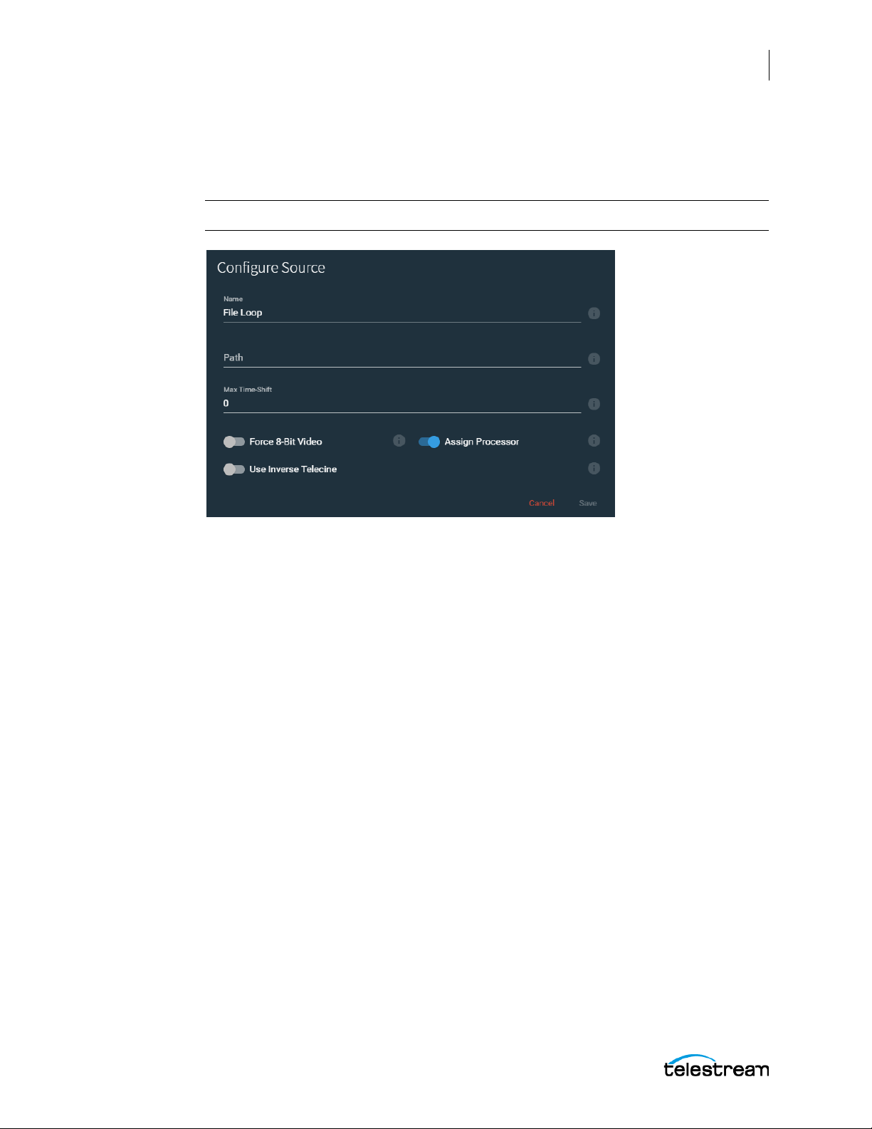
Configuring a File Loop Source
The File Loop Configure Source dialog opens when you create or edit a File Loop source.
Note: File Loops are intended for test purposes only.
Configuring the Lightspeed Live Capture Server and Apps
Managing and Configuring Sources
63
The File Loop Configure Source dialog provides these options:
• Name—Specifies the name of the File Loop.
• Path—Specifies the path for the looping file source.
• Max Time-Shift—Sets the size of the internal Time-Shift buffer that may be used to
delay the source.
• Force 8 Bit Video—Forces the source to be 8 bit instead of 10 bit regardless of orig-
inal source.
• Assign Processor—Assign this source and its dependents to a single processor.
When on, all processing is assigned to a single multi-core CPU socket. This prevents
inefficient mapping of processes across CPU sockets during heavy loads, such as
when all four inputs are being processed. Works for SD/HD sources only, not 4K.
• Use Inverse Telecine—Sets the source to be de-interlaced using Inverse Telecine
settings.
• Simulate Deck—Simulates a VTR tape deck. Only available when Advanced mode
is enabled. Available only in Advanced Mode (System Settings).
• Cisco ID3—Enable to allow the SCTE-104 information to be converted to ID3 on
output. This option can also be turned off or on from Live Capture when configuring SDI sources, see Cisco ID3 in the Configuring SDI Source Options topic in the
Lightspeed Live Capture User Guide. Available only in Advanced Mode.
Lightspeed Live Capture User Guide
Page 64
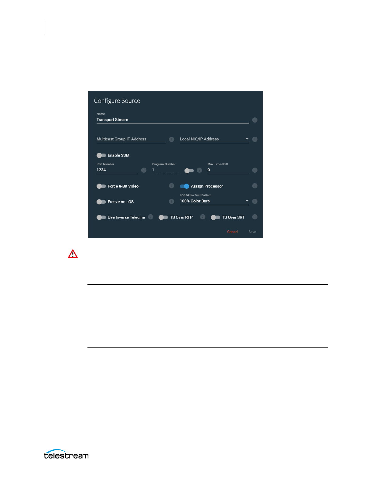
64
Configuring the Lightspeed Live Capture Server and Apps
Managing and Configuring Sources
Configuring a Transport Stream Source
The Transport Stream Configure Source dialog opens when you create or edit a
Transport Stream source.
Note: The settings for Multicast Group IP Address, Local NIC/IP Address, Port Number,
and Program Number can only be changed when you are first adding a new Transport
Stream source. After the source has been added, only the other settings for the
Transport Stream source can be edited.
The Transport Stream Configure Source dialog provides these options:
• Name—Specifies the name of the stream.
• Multicast Group IP Address—The optional Multicast Group IP address to use.
• Local NIC/IP Address—The local NIC (Network Interface Card)/IP address. Select
other ones from the menu, if they are available.
Note: When a new network adapter is added, or changed from disabled to enabled
state, Live services must be restarted for the service to be available in the Local NIC/IP
Address menu. See Stopping and Restarting Telestream Live Services.
• Enable SSM—When Source Specific Multicast is enabled, you can enter a list of
accepted source IP addresses for multicast, under Source Filter.
• Source Filter—Enter a list of accepted IP addresses for the multicast sources. To
add IP addresses to the list, press the Enter key after entering an IP address to add a
new entry line.
• Port Number—Specifies the port number.
Lightspeed Live Capture User Guide
Page 65

Configuring the Lightspeed Live Capture Server and Apps
Managing and Configuring Sources
• Program Number—Set the slide button to the on position to enable, then enter or
t the program number. When disabled, the first available program is used
selec
• Max Time-Shift—Sets the size of the internal Time-Shift buffer that may be used to
delay the source
.
• Force 8 Bit Video—Forces the source to be 8 bit instead of 10 bit regardless of orig-
inal source.
• Freeze on LOS—Causes the source to hold the last good frame if there is a loss of
signal.
• LOS Video Test Pattern—Select the test pattern to display when there is a LOS.
Note: The LOS Audio Test Signal is not available for Transport Stream sources.
• Assign Processor—Assign this source and its dependents to a single processor.
When on, all processing is assigned to a single multi-core CPU socket. This prev
inef
ficient mapping of processes across CPU sockets during heavy loads, such as
when all four inputs are being processed. Assign processor should be applied on
o SD/HD sources, not 4K
t
.
65
.
ents
ly
• Use Inverse Telecine—Sets the source to be de-interlaced using Inverse Telecine
settings.
• TS Over RTP—When enabled, wraps the Transport Stream in an RTP packet.
• TS Over SRT—When enabled, the Transport Stream is sent using the SRT protocol.
• Stream dump—Available when Advanced mode is enabled. When enabled, cap-
tures the Transport Stream source to the location and file you specify, until you tu
th
is Stream dump option off. Type the path, folder, and file name into the Stre
p field. The file extension should be .ts. If the folder you specify does not exis
dum
the new folder and file will be automatically created.
rn
am
• Cisco ID3—Enable to allow the SCTE-104 information to be converted to ID3 on
output. T
ing SDI sources, see Cisco ID3 in the Configuring SDI Source Options topic in th
Lightsp
his option can also be turned off or on from Live Capture when configur-
e
eed Live Capture User Guide. Available only in Advanced Mode.
• Enable Source Filtering—When enabled, you can enter a list of accepted source IP
addresses. To add IP addresses to the list, press the Enter key after entering an
add
ress to add a new entry line
.
IP
SCTE-35 Information and ID3 Tag Pass Through or Insertion
When a Transport Stream source contains SCTE-35 information or ID3 tags, this data is
passed through to the output. SCTE-35 and ID3 data can also be inserted via the
Sources API.
t,
Note: Lightspeed Live Capture requires that an IP input source is formated using
standard frame sizes and frame rates. See the Technical Specifications in the
Lightspeed Live Capture product sheet on the Telestream web site for the supported
formats.
Lightspeed Live Capture User Guide
Page 66
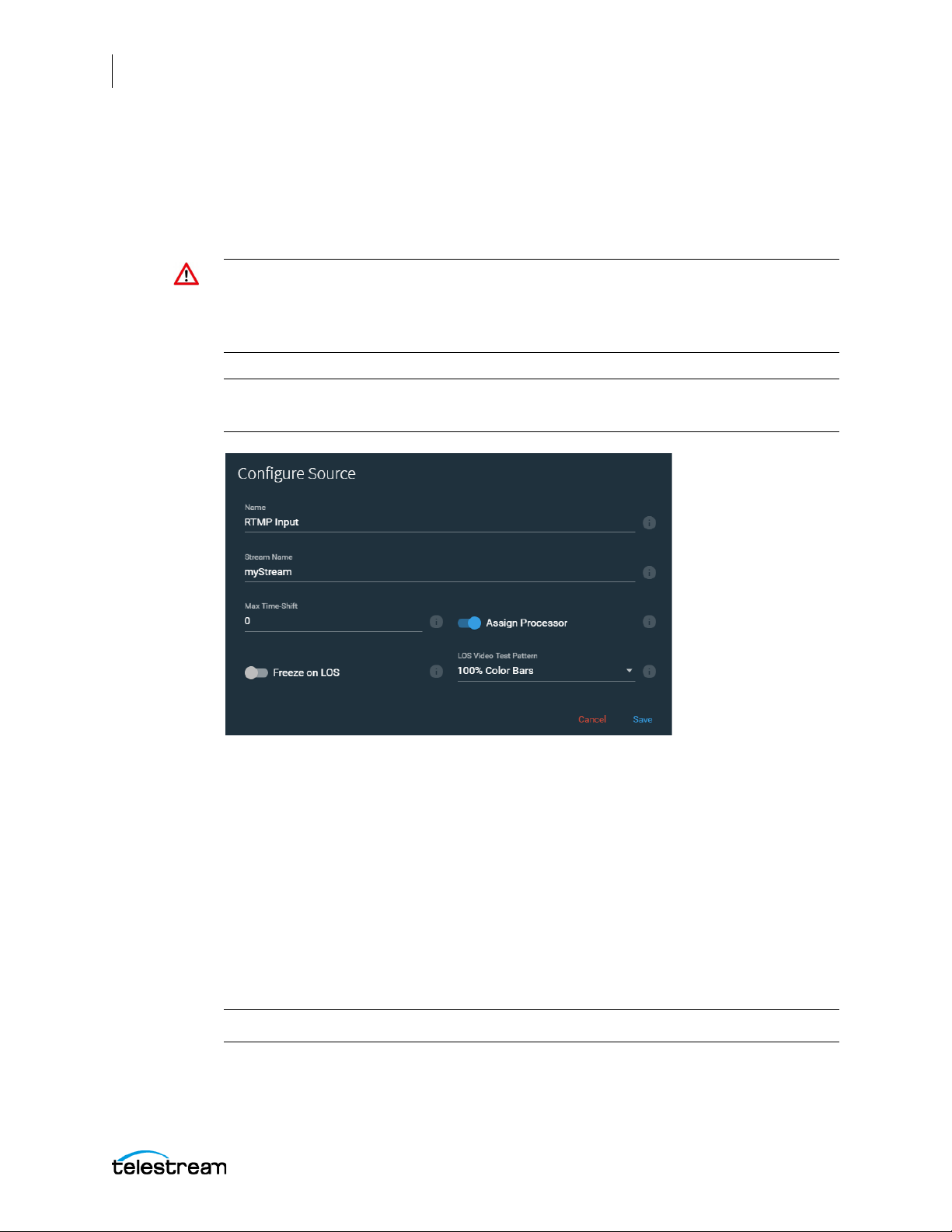
66
Configuring the Lightspeed Live Capture Server and Apps
Managing and Configuring Sources
Configuring an RTMP Source
The RTMP Configure Source dialog opens when you create or edit an RTMP source.
Telestream recommends limiting RTMP/Transport Stream sources to eight, unless
testing in your environment indicates you can enable more.
Note: The options for an RTMP source can only be changed when you are adding it.
After the source has been added, only the name can be changed. When an RTMP
source is connected, the name can’t be changed either. When you require an RTMP
source with different settings, add a new RTMP source and configure it accordingly.
Note: You must first add an RTMP Source to Live Stream before you can start
ingesting the RTMP source.
The RTMP Configure Source dialog provides these options:
• Name—Specifies the name to use in Live Stream.
• Stream Name—Specifies the name of this RTMP stream source. The Stream Name
can be changed multiple times until an RTMP stream source is connected. After an
RTMP stream has connected, the Stream Name can’t be changed.
• Max Time-Shift—Specifies the size of the internal Time-Shift buffer that is used to
delay the source.
• Freeze on LOS—When enabled, causes the source to hold the last good frame if
there is a loss of signal.
• LOS Video Test Pattern—Select the test pattern to display when there is a LOS.
Note: The LOS Audio Test Signal is not available for RTMP sources.
• Assign Processor—When enabled, assigns this source and its dependents to a sin-
gle, multi-core CPU socket. This prevents inefficient mapping of processes across
Lightspeed Live Capture User Guide
Page 67
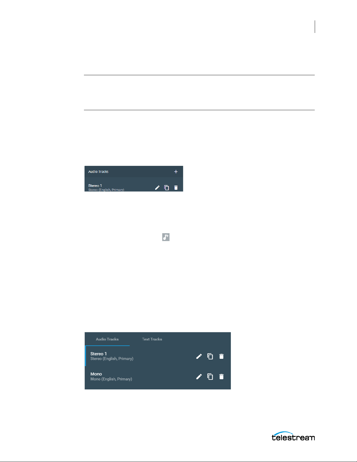
Configuring the Lightspeed Live Capture Server and Apps
CPU sockets during heavy loads, such as when all four inputs are being processed.
Applies to SD/HD sources only, not 4K.
Note: Lightspeed Live Capture requires that an IP input source is formated using
standard frame sizes and frame rates. See the Technical Specifications in the
Lightspeed Live Capture product sheet on the Telestream web site for the supported
formats.
Managing and Configuring Audio Tracks
Audio Tracks are managed in the Preview panel of the Source Manager. The selected
track is displayed when you click Audio Tracks below the video display and includes
configuration tools.
67
Managing and Configuring Sources
An Audio Track is added, by default, when you create a source and it usually is
automatically configured to match the source.
Adding an Audio Track
Click the musical note + icon in the toolbar to add a new audio track. Select Mono |
Stereo | 5.1 Surround. You can add multiple tracks to provide for different languages,
various services, or other variations. The channel assignments can be changed if you
want specific different configurations.
Click the Trash icon in the toolbar to delete the selected track.
Previewing the Audio Tracks
When there is more than one Audio Track, you can select the track that you want to
hear in the Source Preview panel by selecting it from the audio track list. Audio tracks
appear in the list only after you add them as explained above. The track configured as
Default track is the one that you hear if you do not manually select an audio track.
Lightspeed Live Capture User Guide
Page 68
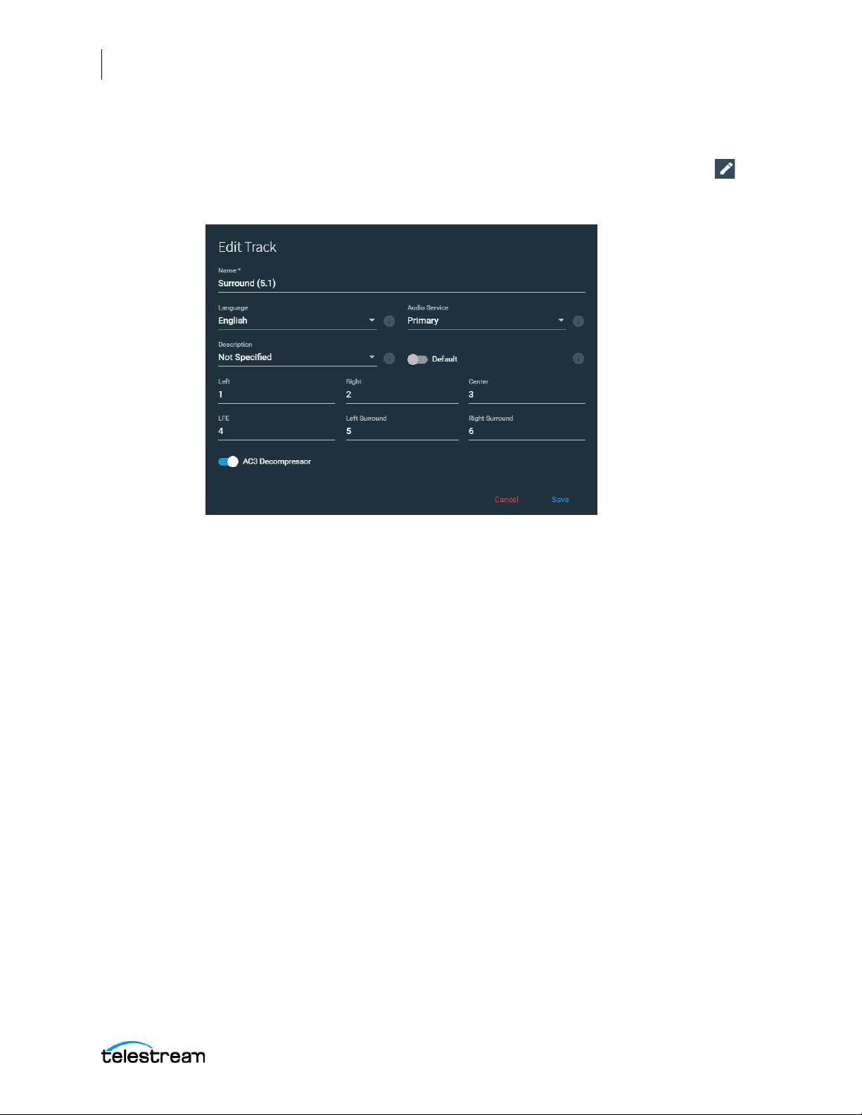
68
Configuring the Lightspeed Live Capture Server and Apps
Managing and Configuring Sources
Configuring an Audio Track
To open the audio track configuration dialog, click the Edit This Track pencil icon for
the track you want to configure. You can change configuration dialog settings to
configure the track as described below.
• Name—Specifies the name of the audio track.
• Language—Specifies the language to use for this track. (Does not affect final output).
• Audio Service—Specifies the audio service label to use for this track: Primary | Sec-
ondary | Commentary | Music. (Does not affect final output).
• Description—Select a description to use for the Audio Track. The descriptions are
cr
eated and edited in the Settings dialog > Audio Descriptions tab of Live Stream
.
• Default—Enable to set the audio track as the default. When enabled, this track is
one used first when you select the input source to preview. You can select a dif-
the
ferent Audio Track to use for the preview from the menu in the upper ri
S
ources panel. Setting a track to Default also marks it as the settings to use for th
Channel Assignment of the output. However, the audio encoder setting determines
the actual channel type of Mono, Stereo, or 5.1 to use fo
r the output.
ght of the
e
• Channel Assignment—Specifies which source channel is assigned to the output
channel. The default for Mono is Center=1; for Stereo is Left=1, Right=2; for Surround (5.1) is Left=1, Right=2, Center=3, LFE=4, Left Surround=5, and Right Surround=6.
• AC3 Decompressor—When enabled, AC3 audio embedded in PCM is decoded at
the source level and passed on as PCM, for use directly in the primary or secondar
outputs and the P
appears in the audio Edit Track panel, where you can enable it. After the AC3 Decompressor is enabled, the affected source’s Live Source process restarts automatically.
review panel of a Live system. The AC3 Decompressor setting
y
Lightspeed Live Capture User Guide
Page 69

Configuring the Lightspeed Live Capture Server and Apps
Configuring Capture Resources
Lightspeed Live Capture employs a browser-based user interface together with
Vantage workflow-based transcoding software to ingest and encode live, live linear, or
tape-based source video into output media files. Lightspeed Live Capture is designed
to run on a single-server Vantage domain, or operate as a node within a multi-server
Vantage array.
Configuring Lightspeed Live Capture consists primarily of setting up Vantage and
customizing Vantage workflows to automate the capture process. The workflows are
made up of individual tasks called actions, which specify what tasks need to be
performed, such as discovering and capturing video sources, transcoding them into
media files, and delivering the files to specified destinations. In the case of Lightspeed
Live Capture, the primary actions are the Capture action and the Tape action.
Before a Lightspeed Live Capture workflow can be activated to capture media, you
must first configure Lightspeed Live Capture and Vantage as follows:
■ Configuring Settings for Your Facility
69
Configuring Capture Resources
■ Using Inputs for Both Live Stream and Capture
■ Configuring Ingest Sources
The program used to perform these tasks is the Vantage Management
Console, which has an icon on your desktop. Later in this chapter we will
guide you in using the console to perform the tasks.
Workflows are designed using a program called the Vantage Workflow
Designer, which is also launched from a desktop icon. We will guide you
step by step in creating and activating a simple Capture workflow that will detect your
sources, encode them, and place your captured files into a storage location.
Once your Capture workflow is activated you're ready to start capturing. Capture
control is performed in the Lightspeed Live Capture web application. The Lightspeed
Live Capture Web API can also be used to control operations.
WAR NING : Do not uninstall the Lightspeed Live Stream application. Components of
the Live Stream application are needed in order for Capture to operate properly.
Lightspeed Live Capture User Guide
Page 70
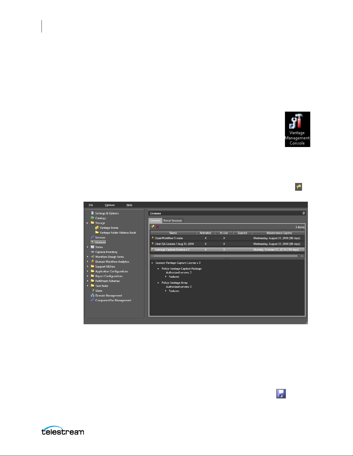
70
Configuring the Lightspeed Live Capture Server and Apps
Configuring Settings for Your Facility
Configuring Settings for Your Facility
A few settings are required on your Lightspeed Live server before you launch the
Lightspeed Live Capture or Tape Capture web application. Some of these settings are
configured at the factory, but you should verify them and make additional custom
settings as follows:
1: Open the Vantage Management Console.
Launch the Vantage Management Console by double-clicking the desktop
icon.
(To learn more about any of the following steps, click the question mark
(?) in the upper right corner of the Console to open the searchable
Vantage Domain Management Guide.)
2: Apply Your License.
Apply your Lightspeed Live Capture license by clicking Licenses in the left panel and
verifying that you have a Live Capture license.
If not, contact Telestream for a license, and click the Add/Update a License button in
the Licenses panel to add the new license.
3: Activate User Administration.
Activate User Administration (or verify that it was activated at the factory.) Select
Settings & Options in the left panel. On the General tab, verify that Enable user
administration is selected, and if not, select it. This must be enabled in order to use the
Lightspeed Live Capture web application.
You may also want to check Use Windows Active Directory for Users to use your Windows
logins for Vantage. Alternatively, you can create Vantage-only users if you leave the
Windows option unchecked. If you made any changes, click the Save icon .
Lightspeed Live Capture User Guide
Page 71
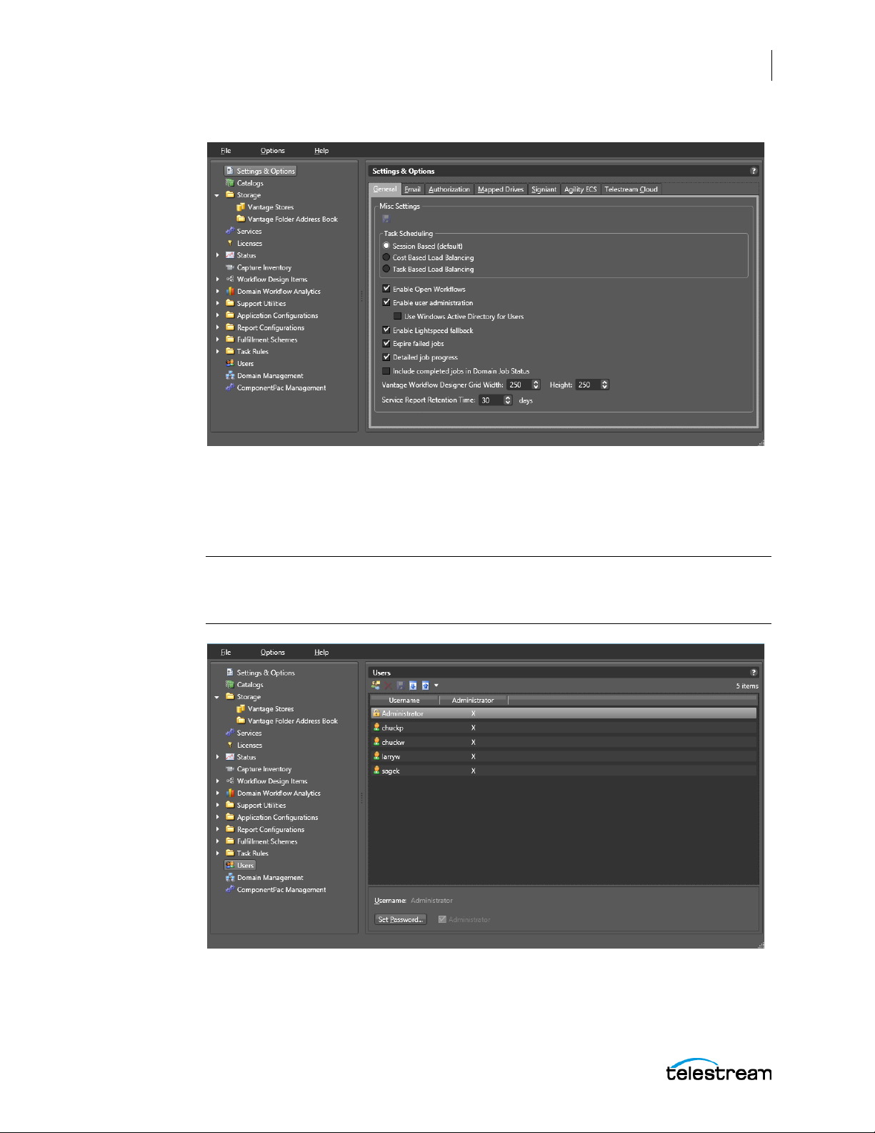
4: Create User Accounts.
Configuring the Lightspeed Live Capture Server and Apps
Configuring Settings for Your Facility
71
Create user accounts for Lightspeed Live Capture. Select Users near the bottom of the
left panel to create new user accounts. To add a new account, click the New User button
in the Users panel and fill in the form. Each Capture user should have a login.
Note: User accounts can be used to control access to the Management Console,
Workflow Designer, Workflow Categories, and Channel Groups; or can prevent
Lightspeed Tape Capture users from competing for the same resources.
5: Add a Live Store for capture files.
Add a Live Store for Capture (or verify that it has been added at the factory). Select
Storage > Vantage Stores in the left panel and verify that a Live Store exists in the D:\Live
Lightspeed Live Capture User Guide
Page 72
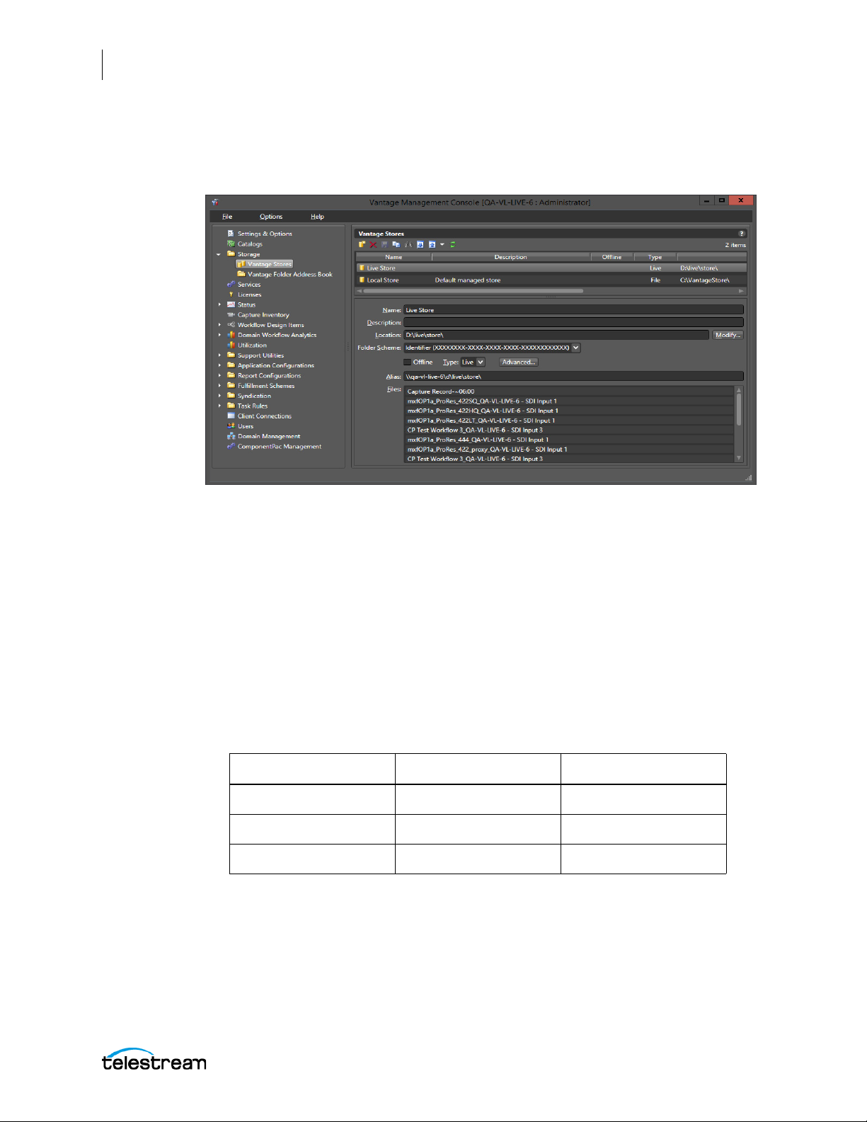
72
Configuring the Lightspeed Live Capture Server and Apps
Configuring Settings for Your Facility
Store\ location. If not, click the New Vantage Store icon, fill out the form, and be sure to
select Type: Live in the form. Also, if a default Vantage Local Store (file type) does not
exist, you will need to create one using this same Vantage Management Console panel.
When to Specify a UNC Path for Live Stores
To ensure Live Stores are properly configured so that captured files can be
automatically deleted when jobs expire, you may need to specify the storage location
as a UNC path. This is especially true if you have multiple servers connected together in
an array. A UNC path is also important when you have multiple users accessing the
Tape Capture application from remote browsers.
A UNC path looks like this: \\hostname\d\live\store.
Follow these steps to configure Live Stores as UNC paths to allow automatic deletion of
deleted and expired capture files:
a. Create a local Live Store for each Lightspeed Live Capture server in the domain.
For example, for Capture servers LSL-01, LSL-02, and LSL-03, create these stores:
Live Store Name Location Store Type
LSL-01 Local Live Store D:\live\store Live
LSL-02 Local Live Store D:\live\store Live
LSL-03 Local Live Store D:\live\store Live
b. Share the Live Stores in Windows as UNC paths on all servers.
c. In the Live Store Alias field, add the UNC path for each source. For example:
Lightspeed Live Capture User Guide
Page 73

Configuring the Lightspeed Live Capture Server and Apps
Configuring Settings for Your Facility
Store
Live Store Name Location
Typ e A lia s
LSL-01 Local Live Store D:\Live\Store Live \\LSL-01\d\live\store
LSL-02 Local Live Store D:\Live\Store Live \\LSL-02\d\live\store
LSL-03 Local Live Store D:\Live\Store Live \\LSL-03\d\live\store
d. Create authorization entries in the Vantage Management Console > Settings and
Options > A
ser
vices into Maintenance Mode and exit them again to apply the change.
uthorization tab for each Live Store UNC path alias. Then put
e. When creating workflows, be sure to assign Capture actions to the Live Stor
c
orresponding to the server where the action resides. For example, assign
all
e
Capture actions on LSL-01 to the LSL-01 Live Store (\\LSL-01\d\live\store).
When to Run Copy and Move Actions on Local or on Any Server
If the Live Store is a local path, then a Copy or Move action following a Capture action in
a workflow should always run on the same machine as the Capture action.
73
If the Live Store is a UNC path, then Copy or Move actions downstream from a Capture
action can run on any machine in the Vantage domain, assuming an array license is
present.
Lightspeed Live Capture User Guide
Page 74
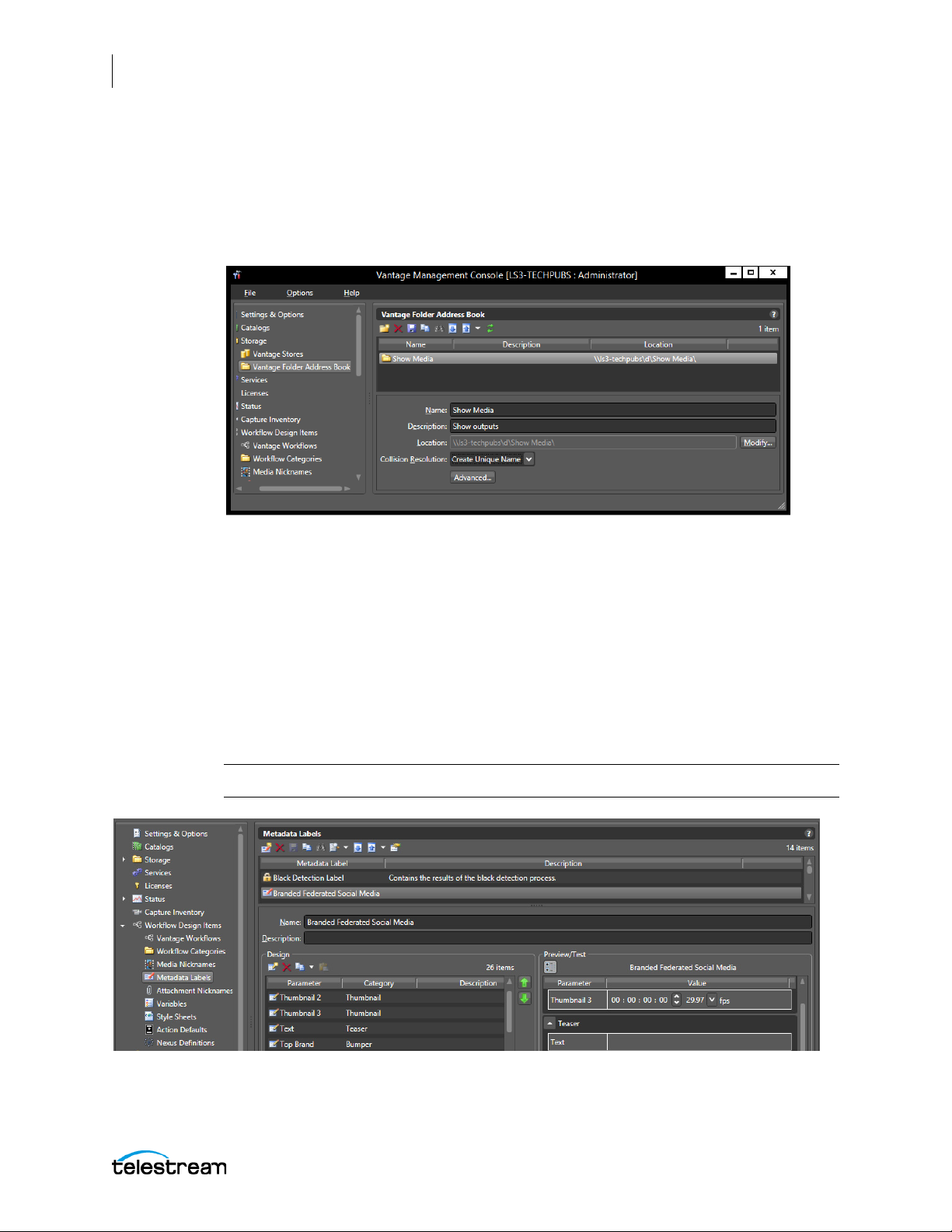
74
Configuring the Lightspeed Live Capture Server and Apps
Configuring Settings for Your Facility
6: Create Address Book Delivery Locations.
Add delivery locations to the Vantage Folder Address Book where captured files can be
written. Click Vantage Folder Address Book and create new address book entries. Folder
locations must be Windows file system locations with a letter drive or network UNC
path.
7: Create Labels and Variables for the Tape and Capture Actions.
Labels and variables you create can be added to the Tape and Capture actions and can
be viewed, included, and modified in the Tape Capture and Live Capture web
applications. For example, you might want to create labels for social media accounts to
post directly to Facebook and YouTube using account and file description metadata
stored in the labels. Similarly, you may want to use or create variables for tape or media
file parameters.
In the Vantage Management Console, add labels using Workflow Design Items >
Metadata Labels. Add Variables using Workflow Design Items > Variables.
Note: An additional Vantage license may be required for social media posting.
Lightspeed Live Capture User Guide
Page 75

Configuring the Lightspeed Live Capture Server and Apps
Using Inputs for Both Live Stream and Capture
Using Inputs for Both Live Stream and Capture
This Note and Warning apply only when Live Stream and Live Capture are used on the
same Lightspeed Live server:
Note: Changing sources in any way on the Source Manager page affects which
sources are available to the Live Capture and Live Stream web applications.
Conversely, changing source configurations in the Live Stream web application
changes what is shown on the Source Manager page.
WAR NING : When Live Stream and Live Capture are used on a server concurrently, any File
Loop or Slate sources that appear on the Source Manager page are NOT supported for
Capture workflows. Do not make any changes to the options for these sources; they are
created by and used by the Stream application.
Configuration changes for these sources are made in the Lightspeed Live Stream web
application. The actual name of the sources created in Live Stream can be any name they
have been given, and may not be called File Loop, RTMP, and so on.
75
Lightspeed Live Capture User Guide
Page 76
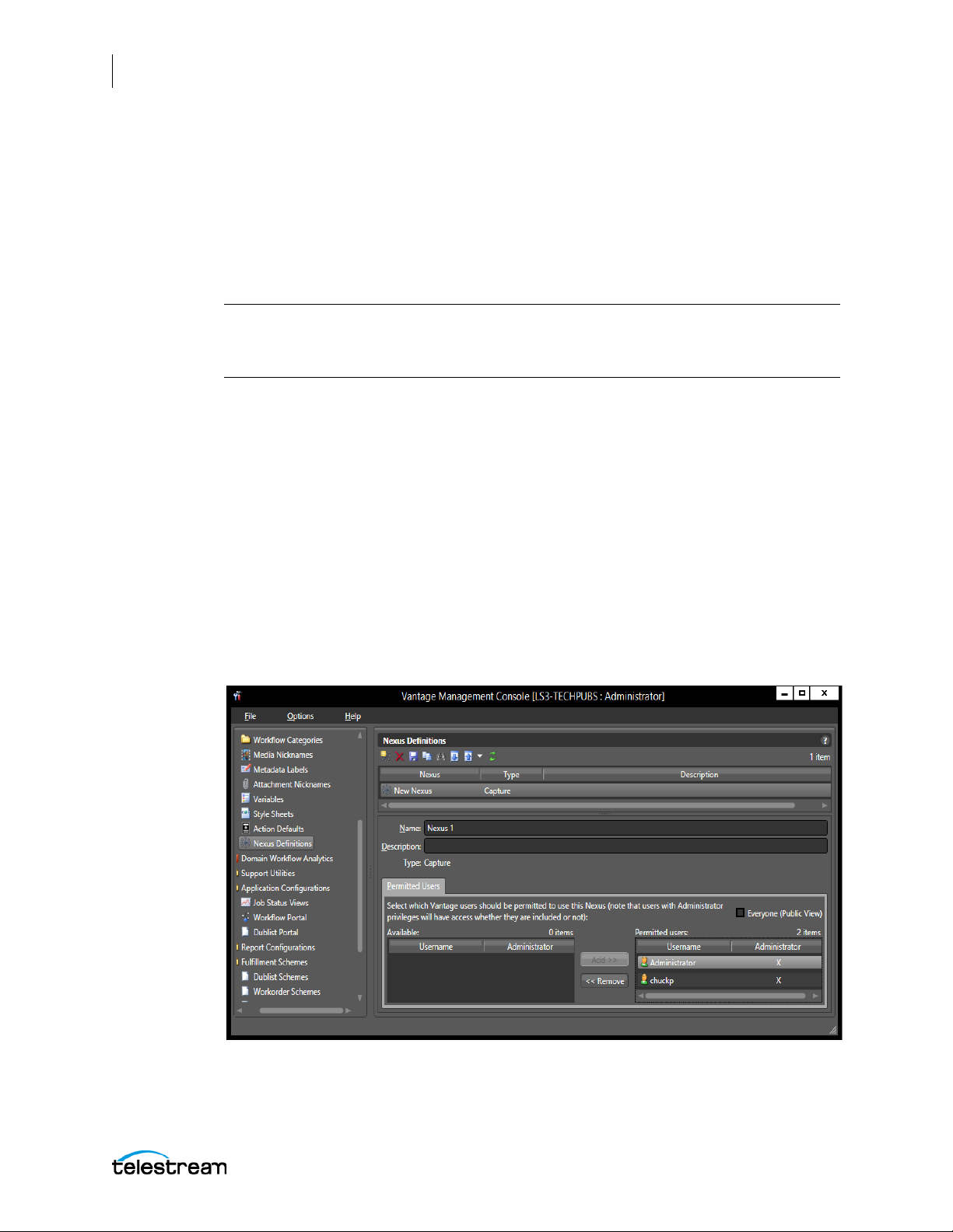
76
Configuring the Lightspeed Live Capture Server and Apps
Configuring Ingest Sources
Configuring Ingest Sources
Before the channel groups and sources can be accessed by the Lightspeed Live Capture
or Tape Capture web app, they need to be defined. This allows the system to work with
the sources according to your workflow and Lightspeed Live Capture or Tape Capture
web app configurations. The workflows and web apps work together, and the
beginning of the inter-operation is to define nexus channel groups and source inputs.
Note: If you have already configured input sources using the Source Manager app
(http://localhost:8090), you will still need to create a Nexus, but you can skip
configuring SDI, IP, and other sources in Vantage as explained by topics below.
Configuring a Channel Group Nexus
Lightspeed Live Capture uses the concept of a nexus to group related video source
channels together. For example, one group of sources might be camera video feeds
coming from the same studio, and another group might come from another studio. A
single source can be referenced in multiple workflows and, hence, in more than one
nexus. The Nexus Definitions created here are called Channel Groups in the Lightspeed
Live Capture web application. There are two types of definitions; one when capturing
from a live source and another when controlling a VTR when capturing from tape. See
Lightspeed Live Capture Web App Overview.
Follow these steps to configure a nexus and an inventory of video sources:
1. Launch the Vantage Management Console.
2. Select Workflow Design Items > Nexus Definitions in the left panel.
Lightspeed Live Capture User Guide
Page 77

Configuring the Lightspeed Live Capture Server and Apps
Configuring Ingest Sources
3. Use the Create a new Nexus definition button in the Nexus Definitions panel to
create at least one Channel Group Nexus definition, setting the type to Capture or
Tape Capture. Workflows built using a Tape Capture origin action ar
T
ape Capture Channel Groups, while workflows built with a Capture origin acti
ar
e assigned to Capture Channel Groups
ect Capture or Ta pe Capture in the dialog that opens, and click OK to ad
4. Sel
.
e assigned to
on
d a new
nexus.
5.
he Name field, type the name you want, and add optional information
In t
scription
De
6. In t
he Permitted Users section (visible only if User Administration is enabled in
S
ettings & Options > General tab) you can assign Permitted Users by clicking on a
field.
user in the left list, and clicking Add to move them to the right list. You can ch
E
veryone (Public Access) (this is the default) to allow all users access to that nexus.
Use Remove to move a selected user on the right to the non-permitted list on th
lef
t. This disables that user’s access. Each nexus can have its own Permitted Users.
in the
the
eck
e
77
The list of Available users is created by adding user accounts in the Users panel. Se
C
onfiguring Settings for Your Facility for instructions
.
Note: Users with administrator privileges will have access whether they are included,
or not, in the Permitted Users list.
7. Click Save to save the changes and create a new channel group nexus.
e
Lightspeed Live Capture User Guide
Page 78
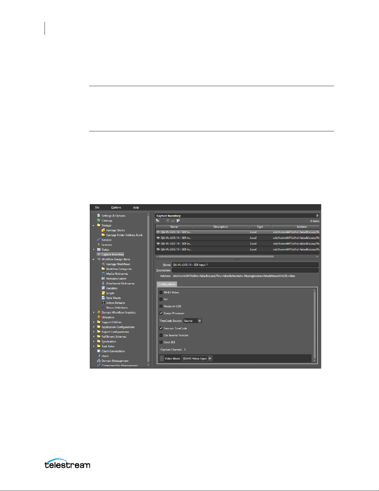
78
Configuring the Lightspeed Live Capture Server and Apps
Configuring Ingest Sources
Using Capture Inventory to Preview and Find Workflows Used by an Input
Note: The process of managing and configuring input sources for Live Capture has
changed in v3.0 (and later). All source management and configuration should now
done from the Source Manager page (see below for details). The Capture Inventory
panel within the Vantage Management Console should be used for discovering
Workflows and Previewing the Inputs only.
SDI Sources are configured using the Source Manager user interface at http://localhost:
8090, described under the topic Managing and Configuring Sources. The Capture
Inventory panel in the Vantage Management Console (VMC) allows the user to discover
which workflows are configured to use a particular input and can display a Preview of the
inputs configuration. All SDI sources present on a Lightspeed Live system are
automatically added to the inventory list of sources.
Select Capture Inventory in the left panel to open the Capture Inventory panel.
Lightspeed Live Capture User Guide
Page 79
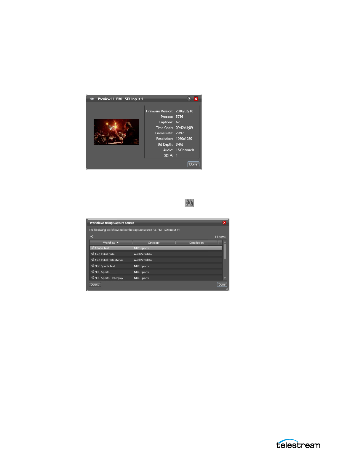
Configuring the Lightspeed Live Capture Server and Apps
Configuring Ingest Sources
Previewing Sources
You can preview source video and see information about it in a small window (below)
by using the Preview button in the Capture Inventory toolbar. The preview image is
updated once per second.
Finding Workflows
You can determine which workflows are configured to use a specific input source by
selecting the Find Workflows button in the Capture Inventory toolbar. A list of
associated workflows will appear.
79
Lightspeed Live Capture User Guide
Page 80

80
Configuring the Lightspeed Live Capture Server and Apps
Installing the Live Capture & Tape Capture Web Apps
Installing the Live Capture & Tape Capture Web
Apps
Lightspeed Live Capture and Tape Capture are web applications that come preinstalled on Lightspeed Live Capture servers. The applications are facilitated by IIS
(Windows Internet Information Services) which ships properly configured in the
Lightspeed Live Capture server.
Installation on Standard Servers
To install Live Capture and Tape Capture on standard servers (other than Lightspeed
Live Capture), you must set up IIS first. If IIS is already installed, you must create the
configuration that supports Vantage Web Applications.
For full details about setup for standard servers, see “Installing and Configuring Vantage
Web Applications” in the Vantage Installation Guide or the Domain Management Guide.
An easy way to access the Domain Management Guide is to open the Vantage
Management Console and click the ? in the upper right corner.
See Configuring Settings for Your Facility for information about the Vantage
Management Console.
The following are additional helpful topics to search for in the Vantage Installation
Guide or the Domain Management Guide:
• “Server Hardware Requirements”
• “Vantage Web Applications OS”
Clear Browsing Data after Updating
After a Vantage or Live Capture ComponentPac update is installed, you must clear the
browsing data in your Chrome browser in order for the Lightspeed Live Capture or Tape
Capture web applications to operate properly. See Clear Browsing Data after Updating
Vantage or Live Capture for detailed information.
Lightspeed Live Capture User Guide
Page 81

Configuring the Lightspeed Live Capture Server and Apps
Renaming or Reconfiguring Servers
The following topics explain how to make common configuration changes.
■ Array Licensing for Multiple Server Live Capture Systems
■ Important Notes on Configuring Non-Capture Workflow Actions on Multiple Server
Syste
ms
■ Joining Multiple Capture Servers
■ Uniquely Named Multiple Capture Servers
■ Best Practice for Multiple Live Capture Server System Design
■ Connecting the Applications for Multiple Servers
■ Correcting Thumbnail Appearance on Non-Local Systems
Lightspeed Live Stream servers do not include Vantage as part of the product.
However, Lightspeed Live Capture includes Vantage pre-installed as part of the
product, and the Capture Vantage domain uses the name assigned to the Windows
server that hosts the Vantage domain database as its domain name. Consequently,
renaming the Capture server includes steps to rename the Vantage domain that do not
apply to renaming a Live server.
81
Renaming or Reconfiguring Servers
Renaming a Capture or Stream/Capture Server—Follow all of these steps for a
Capture server, but for a Stream server, skip any steps pertaining to Vantage.
Renaming a Stream Only Server—Follow steps 6 through 12 only (ignore all Vantage
steps).
If you want to rename your Lightspeed Live server and keep the pre-installed Vantage
database, you’ll complete the following tasks to ensure that your database is updated
with the new machine name (detailed steps following):
• Remove all Vantage services from the Vantage domain.
• Rename the Windows server that hosts the Vantage domain database.
• Restart the renamed server and add all Vantage services to the renamed domain.
CAUTION: The server name must be limited to 15 characters or less.
Note: To complete this procedure, your Windows user must have permission to
rename the computer, or you must get assistance from your Windows domain
administrator. Be sure to schedule the rename during a maintenance window, as
renaming the Vantage domain interrupts all Vantage services in the domain and all
Windows services on the server are renamed.
Use the following steps to rename a Vantage server and domain.
1. Start the Vantage Management Console, select the domain to manage, and log on
as described in Starting the Vantage Management Console in the Vantage Doma
M
anagement Guide.
2. Select Services in the component panel.
Lightspeed Live Capture User Guide
in
Page 82

82
Configuring the Lightspeed Live Capture Server and Apps
Renaming or Reconfiguring Servers
3. Take note of Storage, Variables, and/or Qualification Rules settings for each service
that you have configured. Write down any Storage, Variable, and/or Qualification
Rule settings that you want to reconfigure after the Vantage domain is renamed.
Note: When you remove Vantage services from the domain, the Storage, Variable,
and Qualification rule configuration for each service is lost. The rest of the Vantage
domain configuration is retained. If you are changing the machine name during initial
server installation, no custom rules have been configured, so this does not apply.
4. Click a service in the Services details panel, then press Ctrl-A to select all services.
5. Click the Remove Service button in the toolbar.
6. Open the Windows Server Manager by clicking Windows Start Menu >
Administrative Tools > Server Manager.
7. Click Local Server in the left pane.
8. Select the Computer Name tab and click Change.
9. Enter the new computer name in the Computer Name text field and click OK. This
new computer name becomes your new Vantage domain name.
10. If prompted to do so, enter a Windows user name and password for an account that
has permission to rename this computer in the Windows domain.
11. Restart the server.
12. Start the Vantage Management Console, select the new domain, and log on.
- If you are not prompted to select the new domain, click on File > Change Vantage
Domain, click Search, select the new domain and click OK.
13. Select Services in the Component panel.
14. Click the Add Service button
in the toolbar.
Note: If you are not able to log in with the local Administrator account, check the
hostname listed by Windows as it may not have been updated. For example, if the
original hostname was lsl-telestream and the new one is lsl-customer, the User Name
may still be listed as: lsl-telestream\Administrator. If so, change the hostname to:
lsl-customer\Administrator, and re-enter your password.
Lightspeed Live Capture User Guide
Page 83

Configuring the Lightspeed Live Capture Server and Apps
Renaming or Reconfiguring Servers
15. When the Select Service dialog appears, click Machine to sort the services by
machine name.
16. To add Vantage services for a specific machine, select the services you want and
click OK.
17. If any Storage, Variables, and/or Qualification Rules settings were configured for
services, add them now.
18. Send the new Vantage domain name to all Vantage users and administrators so
they can reconnect to the Vantage domain.
This completes the renaming procedure.
83
Lightspeed Live Capture User Guide
Page 84

84
Configuring the Lightspeed Live Capture Server and Apps
Renaming or Reconfiguring Servers
Array Licensing for Multiple Server Live Capture Systems
The need for array licenses will vary, depending on whether the Vantage domain is
operating on a single server or on multiple servers, which is called a Vantage array.
Vantage and Live Capture Solutions
Array licenses are required on each Vantage and Live Capture server when they are
connected together within a single Vantage Domain.
• Live Capture server licenses automatically include an array license instance as part
of your purchase of the Live Capture server. No additional purchase is required for
these servers.
• All Vantage servers joined together with Live Capture servers within a single
domain require an array license to be purchased for each Vantage server.
The following examples illustrate the requirements for purchasing and licensing
Vantage domains containing Live Capture servers.
New Vantage Systems Containing Live Capture
• Example 1: A brand new system consisting of two Lightspeed Live Capture servers
and two Vantage servers that are joined into a single domain requires a total of four
array licenses. For this system you order two array licenses for the Vantage servers
and receive a domain license file containing array license instances for all four servers; two purchased for the Vantage servers and two included with your Lightspeed
Live Capture servers.
• Example 2: A brand new system consisting of five Lightspeed Live Capture servers
and three Vantage servers that are joined into a single domain requires a total of
eight array licenses. For this system you order three array licenses for the Vantage
servers and receive a domain license file containing array license instances for all
eight servers; three purchased for the Vantage servers and five included with your
Lightspeed Live Capture servers.
Adding Live Capture to an Existing Vantage Domain Array
• Example: If you are adding one or more Lightspeed Live Capture servers to an
existing Vantage domain that already has array licensing for the Vantage servers, no
additional array licenses need to be ordered. For these types of systems you will
need to have the existing Vantage domain license updated to include Live Capture
and an associated array license for each Live Capture server added to it.
Lightspeed Live Capture User Guide
Page 85

Configuring the Lightspeed Live Capture Server and Apps
Renaming or Reconfiguring Servers
Important Notes on Configuring Non-Capture Workflow Actions on Multiple Server Systems
Live Capture server licenses automatically include an array license instance as part of
your purchase. When Live Capture workflows are created and executed, all Capture
origin action processes will run on their respective Live Capture servers automatically.
However, other services such as the Transport or Deploy service, can run on any server
with available resources for the desired service's action. The following describes the
best practices for configuring storage settings when using non-Capture actions.
Best Practice When Capturing to a Live Capture Local Media Drive:
When you are capturing directly to a Local Live Store that is set to a local drive letter's
folder, any workflow action immediately following the Capture Action will be processed
locally. For actions that do not immediately follow the Capture Action, it is best to set
“Run On Rules” that instruct the non-Capture action processes to run on the Live
Capture server where the media resides. This insures that the non-Capture action
process will run directly on the server where the media resides. See the “Configuring an
Action's Run On Rules” section of the Vantage User Guide for more information. CAP2345
85
Best Practice When Capturing to Shared External Storage:
When you are capturing to a shared external storage location, such as a NAS or SAN,
you can allow other non-Capture action processes to run on any server with available
resources. In this case “Run On Rules” are not required. Your system will automatically
choose an available resource on any server that can run the required action's process.
Note: Running Lightspeed Live Capture and Vantage together without array licenses
is not recommended and may result in reduced functionality.
See Joining Multiple Capture Servers below for information about setting up an array.
Lightspeed Live Capture User Guide
Page 86

86
Configuring the Lightspeed Live Capture Server and Apps
Renaming or Reconfiguring Servers
Joining Multiple Capture Servers
Your Lightspeed Live Capture server is factory-configured as a standalone live Capture
system. This configuration includes a Vantage database running on each standalone
Live Capture server. If you plan to manage multiple Live Capture servers from a
common interface, or add Live Capture servers to an existing Vantage Array, you can do
this in two ways:
• For Capture-only systems, join all Live Capture servers together by creating a sys-
tem that utilizes a single domain database.
• For Capture systems that will be utilizing other Vantage services and actions, such
as Transcoding and Analysis, you can add your Live Capture servers to an existing
Vantage Array.
Best Practice When Joining Two or More Live Capture Servers Into a Single Domain
The system Database and the Live Capture web application traffic can affect the
performance of a Live Capture server when run in a domain containing more than one
Live Capture server. Therefore, when joining two or more Live Capture servers together
into a single domain, either as a Capture-only solution or into an existing Vantage
server domain, it is highly recommended that the Live Capture/Vantage Database and
IIS software hosting the Live Capture/Vantage web applications run on an independent
non-Live Capture/Vantage server. See images below and Best Practice for Multiple Live
Capture Server System Design.
Further information regarding running the Database and IIS on non-Live Capture/
Vantage servers can be found in the Vantage Domain Management Guide on the
Telestream web site.
It is also highly recommended that the process of creating multiple server domains
containing Live Capture servers be done as part of the installation and commissioning
phase.
Important Note: When standalone Lightspeed Live Capture servers are combined
together using a single database, only those ComponentPacs properly installed on the
master domain database will be utilized. When joining Lightspeed Live Capture
servers together into a Live Capture-only system, or into an existing Vantage Array,
always verify that all of the required ComponentPacs are properly installed on the
combined system's master domain database. For details on how to install
ComponentPacs see Updating Capture using Secured Version Control and
ComponentPacs below.
Lightspeed Live Capture User Guide
Page 87
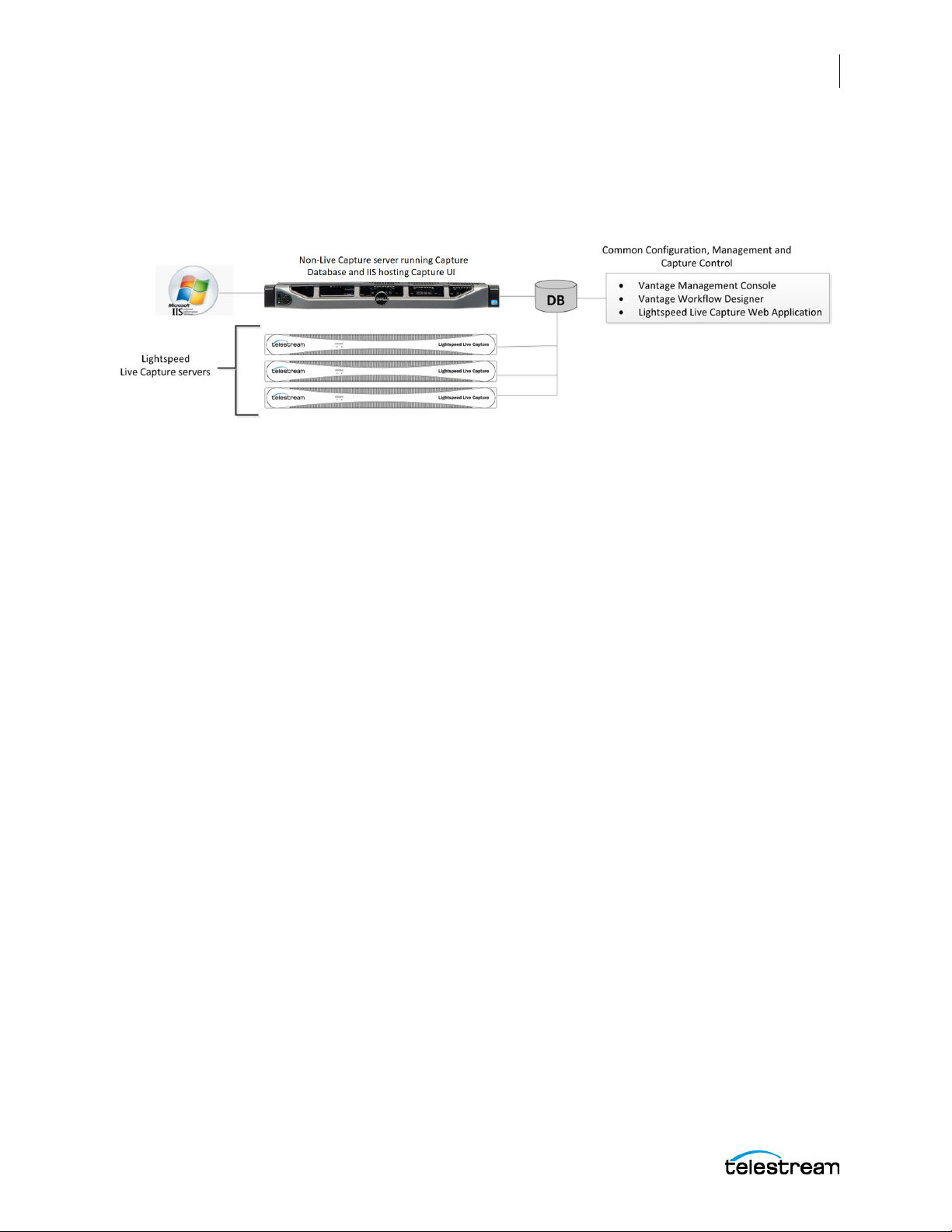
Configuring the Lightspeed Live Capture Server and Apps
Renaming or Reconfiguring Servers
Joining Capture-Only Systems
Two or more Lightspeed Live Capture servers can be joined together to form a multiple
server Live Capture-only system. This allows for common configuration, management,
and capture control.
To join Lightspeed Live Capture servers together, follow these steps:
1. Select one of your Lightspeed Live Capture servers to act as the master domain.
The master domain server system contains the common database and will have all
the services running on other Lightspeed Live Capture servers added to it via the
Vantage Management Console.
87
2. Add all services running on your Lightspeed Live Capture servers to the Lightspeed
Live Capture master domain server. See the Vantage Domain Management Guide for
details on adding services.
3. Apply the appropriate multiple-server Vantage license onto the system running the
master domain database. See the Vantage Domain Management Guide for details
on licensing.
To configure, manage, and control your Lightspeed Live Capture system, run the
Vantage Management Console, Vantage Workflow Designer, and Lightspeed Live
Capture web applications pointing to the domain contained on the Lightspeed Live
Capture master domain server selected in Step 1, above.
Also see, Important Notes on Configuring Non-Capture Workflow Actions on Multiple
Server Systems.
Lightspeed Live Capture User Guide
Page 88
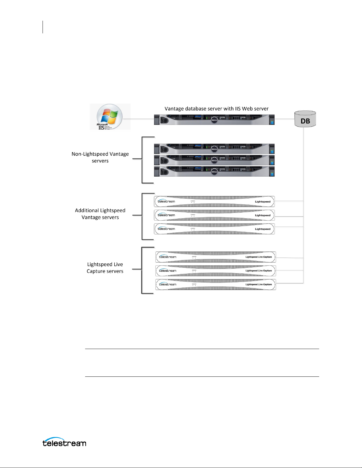
88
Configuring the Lightspeed Live Capture Server and Apps
Renaming or Reconfiguring Servers
Existing Vantage Array - Adding Live Capture Server(s)
Joining Lightspeed Live Capture systems to an existing Vantage Array allows Vantage
workflows to begin with a Capture origin action that is connected to other Vantage
actions and services, such as general transcoding, IPTV/VOD transcoding, analysis, third
party application control, delivery options, or other service/action types.
Adding Services
The Lightspeed Live Capture server includes Vantage services, so adding these services
to an existing Vantage Array is no different than adding any other Vantage service
running on a separate server to a Vantage Array.
Important Note: Joining Live Capture services to an existing Vantage Array requires
the appropriate Vantage Array licensing. See the Vantage Domain Management
Guide for details.
To add Lightspeed Live Capture services to a Vantage Array, follow these steps:
1. Verify that the Lightspeed Live Capture services are running, all Vantage Services
are running on the server, and no jobs are being processed in the local, factoryinstalled All-In-One domain.
Lightspeed Live Capture User Guide
Page 89

Configuring the Lightspeed Live Capture Server and Apps
Renaming or Reconfiguring Servers
2. Verify that you have configured the other (non-Lightspeed) Vantage domain server
with Array, and it is active. Refer to the Vantage Domain Management Guide >
Installing a Vantage Distributed Domain, for more details.
3. Verify that the Lightspeed Live Capture server is on the same network as the
existing Vantage Array domain, with sufficient network permissions and access.
Refer to the Vantage Domain Management Guide > Network Requirements, to
configure your network.
4. Start the Vantage Management Console, and select the new Vantage Array domain.
5. Add the services on the Lightspeed Live Capture server to the new Vantage Array
domain, just as you would do with any Vantage Services running on any Vantage
server.
6. Apply the appropriate multiple-server Vantage license onto the system running the
master domain database. See the Vantage Domain Management Guide for details
on licensing.
Also see, Important Notes on Configuring Non-Capture Workflow Actions on Multiple
Server Systems.
89
Uniquely Named Multiple Capture Servers
To ensure each capture source has a unique name when multiple Live Capture servers
are part of a multi-server Capture-only system, or part of an existing Vantage array, you
will need to change the default source names to make them unique and identifiable.
Source names default to “SDI Input [1 through n]”, where ‘n’ is 4 or 8 depending on
which Lightspeed Live server you have.
For example, by default, Source names for a 4 channel Live Capture server will be:
SDI Input 1, SDI Input 2, SDI Input 3, and SDI Input 4
If you change source names by using the Source Manager, keep in mind that all sources
in an array must be uniquely named so you can easily distinguish sources on one server
from another.
Lightspeed Live Capture User Guide
Page 90
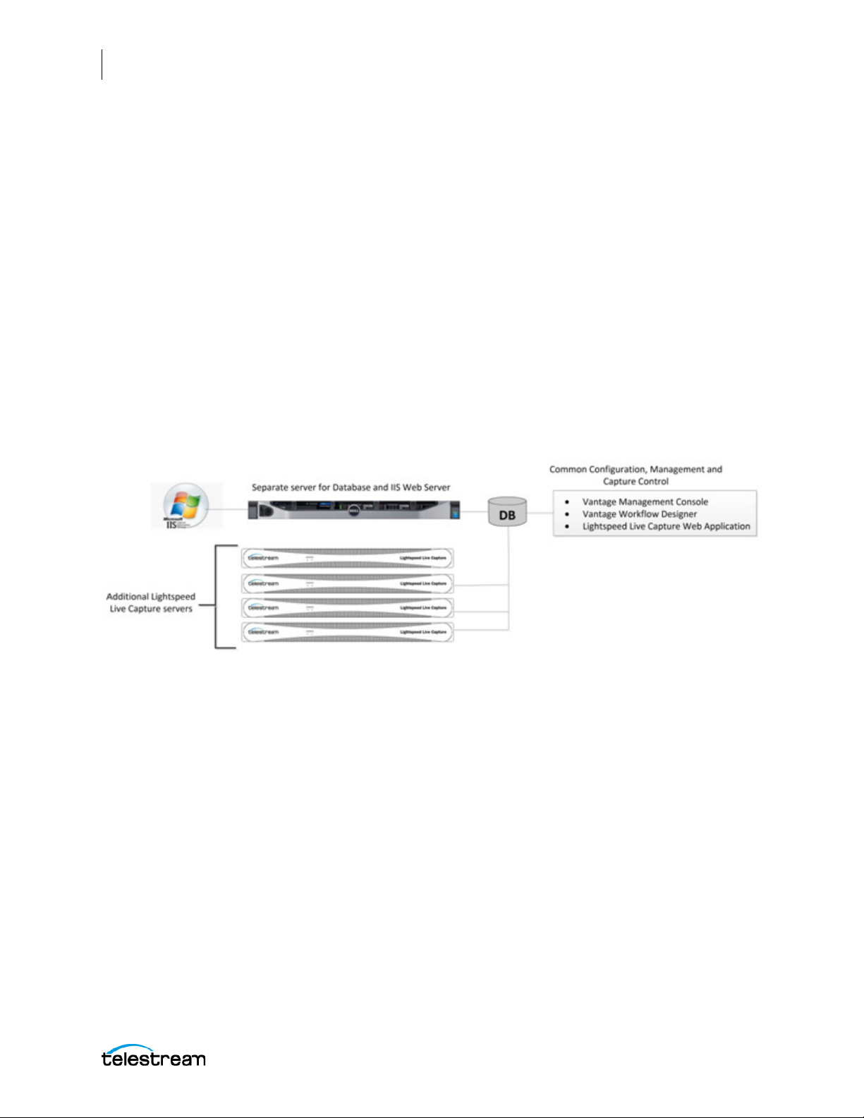
90
Configuring the Lightspeed Live Capture Server and Apps
Renaming or Reconfiguring Servers
Best Practice for Multiple Live Capture Server System Design
The best practice for using multiple Live Capture server systems is to install and run the
Vantage master domain database and IIS Web Server on a server(s) that is separate
from the Live Capture servers. See the Vantage Domain Management Guide for details
on how to install a Vantage Database and Microsoft's IIS Web Server.
When clustering two or more Live Capture and Vantage servers together, it is best to
use a separate server designated as the IIS Web Server to host the Live Capture Web
application. Ideally, the web host should be separate from the Vantage master domain
database system since both IIS and SQL can consume a considerable amount of system
resources.
The following are two example systems utilizing a separate Database and IIS Web
Server.
Capture-only System
For this Capture-only system example, the Vantage master domain database and IIS
Web server are installed together on a separate server. This prevents database or Web
server resources consumption from affecting the Live Capture servers.
Lightspeed Live Capture User Guide
Page 91
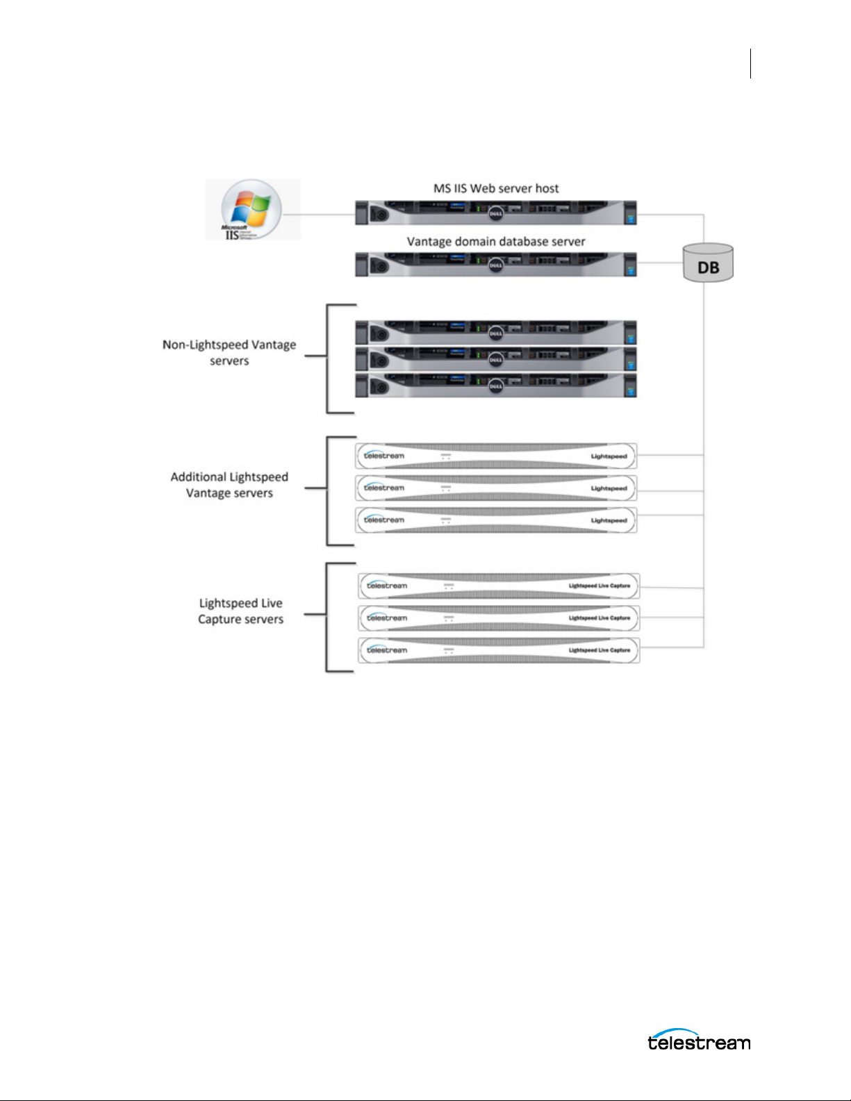
Configuring the Lightspeed Live Capture Server and Apps
Renaming or Reconfiguring Servers
Live Capture/Vantage Array—with Separate Vantage Domain Database
and IIS Web Host Servers
91
For this example the Vantage master domain database and IIS Web server are installed
on two completely separate servers. Since this is a large system array containing six (6)
Vantage system and three (3) Live Capture servers, separating the database and Web
Server is recommended to prevent the database and IIS Web server resource
consumption from affecting the Live Capture and Vantage servers.
For additional information on best practices for Vantage and Vantage Databases, refer
to the Vantage Domain Management Guide and the publication Planning and Setting
Up a Vantage Database on the Telestream.net web site.
Lightspeed Live Capture User Guide
Page 92
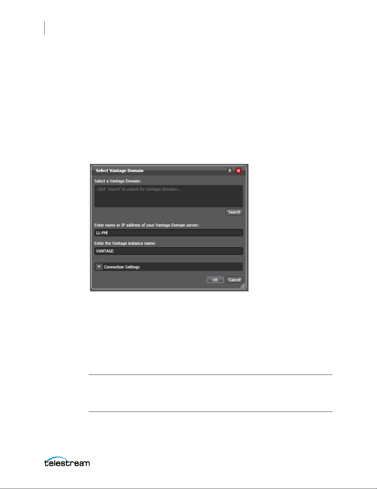
92
Configuring the Lightspeed Live Capture Server and Apps
Renaming or Reconfiguring Servers
Connecting the Applications for Multiple Servers
When there are multiple Capture server systems where the database and web server
reside on specific server(s) within the multiple server configuration, the Vantage client
applications and/or the Live Capture web application need to be configured to connect
to the appropriate server.
Configuring Vantage Client Applications for Multiple Servers
Since the database in a multiple server system is located on a separate server, the
Vantage client applications must "point to" that database. This is done by selecting the
database server from the Select Vantage Domain dialog in the Vantage client
applications.
Using the Vantage Desktop Client Applications
First, install the Vantage Management Console and Vantage Workflow Designer client
applications on any Windows system on your network. To use these client applications,
you must change the Vantage Domain so they connect to the server that is running the
Vantage master domain database.
Select Change Vantage Domains from the File menu of each client application to open
the Select Vantage Domain dialog.
Note: To learn more about the Vantage Management Console or Vantage Workflow
Designer, click the ? icon or use the Help menu to open the searchable Vantage User
Guide. The ? opens to the topic that matches the area of the user interface that you are
using.
Lightspeed Live Capture User Guide
Page 93
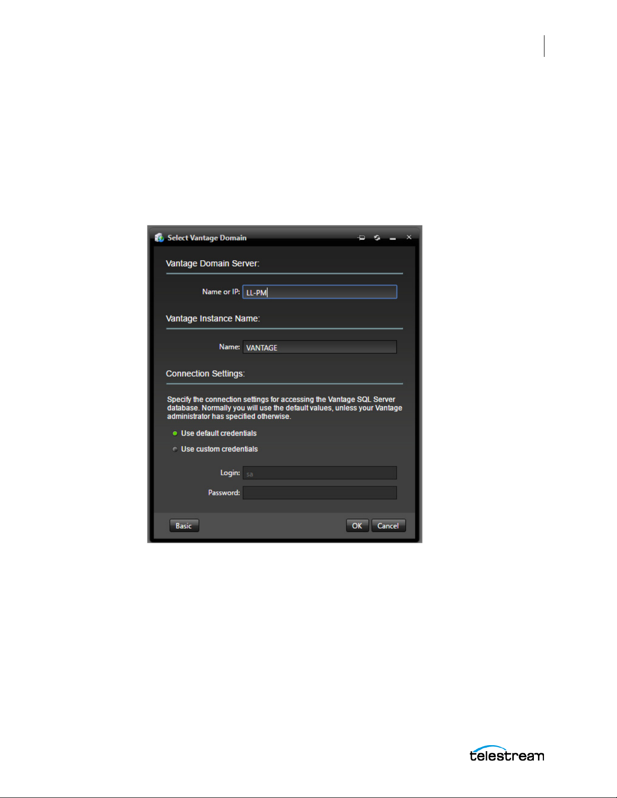
Configuring the Lightspeed Live Capture Server and Apps
Renaming or Reconfiguring Servers
Using the Live Capture Web App with Multiple Servers
To use the Lightspeed Live Capture web application when there are multiple servers,
first install the Vantage Web Applications on the server running the IIS Web service. To
open the Lightspeed Live Capture web application, use the following URL:
http://[Name or IP Address of server running IIS Web service]/Vantage/
CapturePortal/Default.aspx
When asked to select a Vantage Domain, choose the server hosting the Vantage master
domain database.
93
Lightspeed Live Capture User Guide
Page 94
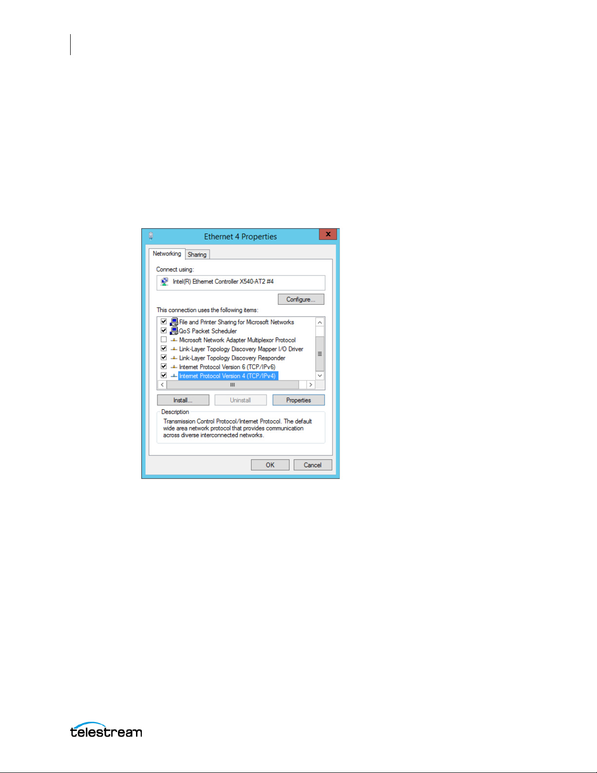
94
Configuring the Lightspeed Live Capture Server and Apps
Renaming or Reconfiguring Servers
Using NetBIOS Hostnames Instead of External Name Server
A multi-node Live Capture system can be used without an external name server, when
NetBIOS is enabled in the database server and all nodes.
Configure the following settings in all servers to enable NetBIOS:
1. Open the Control Panel and select Network and Sharing Center
2. Select the Change Adapter Settings option to open Network Connections.
3. Right-click on the network connection to be changed and select Properties. The
Properties dialog opens:
4. Select TCP/IPv4 and click the Properties button. The TCP/IPv4 dialog opens:
Lightspeed Live Capture User Guide
Page 95
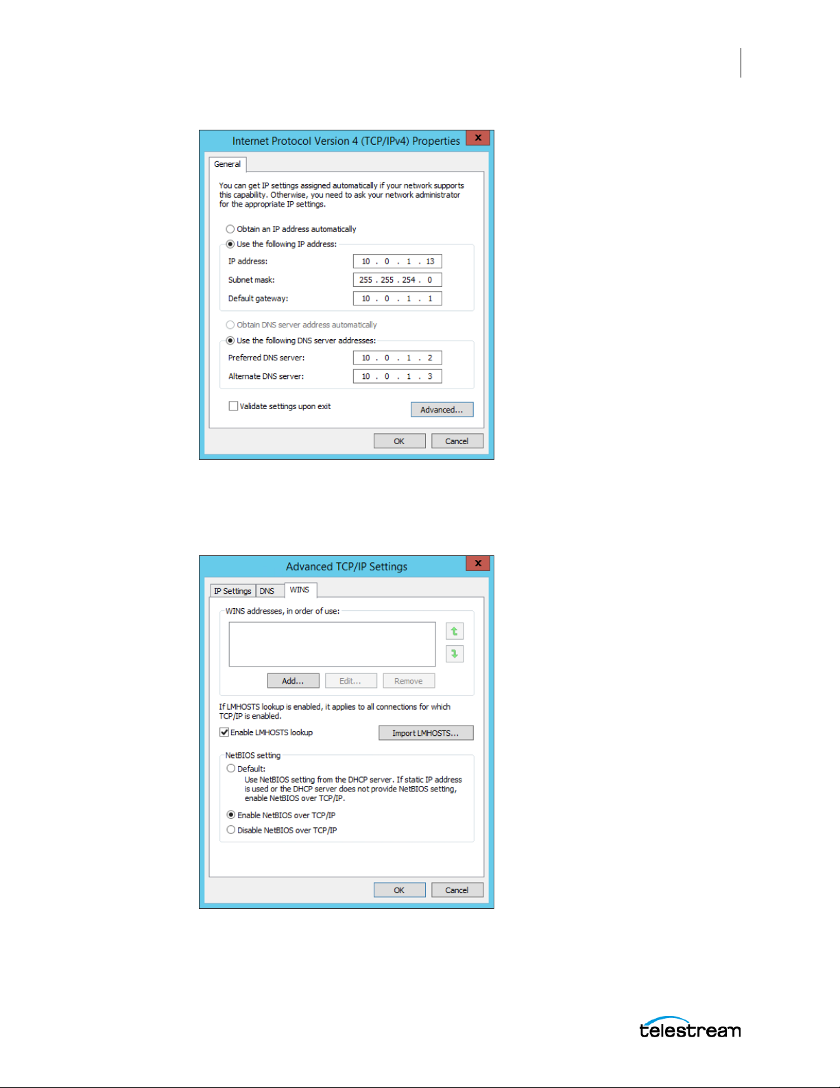
Configuring the Lightspeed Live Capture Server and Apps
Renaming or Reconfiguring Servers
95
5. Configure the IP Address, unique for each server.
6. Configure the Subnet Mask, Default Gateway, and the DNS server addresses. Use
the same addresses for each server.
7. Click the Advanced button. The Advanced dialog opens:
8. In the Advanced dialog select the WINS tab, then select Enable NetBIOS over TCP/IP.
9. Click OK in all dialogs to save the configuration.
10. Reboot the server you just configured, then configure all other servers.
Lightspeed Live Capture User Guide
Page 96

96
Configuring the Lightspeed Live Capture Server and Apps
Renaming or Reconfiguring Servers
Correcting Thumbnail Appearance on Non-Local Systems
When using the Live Capture Web Application from a non-local machine, a user may
see "No Event" instead of the video thumbnails. If so, you will need to update the hosts
file on the computer you are using to access the Web Applications. The following
procedures describe how to correct this is for Apple and Windows machines.
Apple Computer Procedure to Correct Thumbnail Appearance
On an Apple computer, you will add the server IP address and hostname to the
/etc/hosts file and save it. Perform the following procedure:
1. Open the Terminal application by going to Application > Utilities and doubleclicking Terminal.app.
2. Type the following command and press Return: sudo nano /etc/hosts
3. Enter the administrator password for the computer and press Return.
4. Move the cursor using the arrow keys and position it after all of the text in the
window. Then type the IP address of your Lightspeed Live Capture server.
For example: 102.54.94.97
5. Press the Tab key, then type the hostname of the Lightspeed Live Capture server.
For example: CaptureServer1
6. Hold down the Control and 0 keys.
7. Press the Return key.
8. Hold down Control and X to exit.
9. Flush your DNS by typing the following command in the Terminal and pressing
Return:
sudo killall -HUP mDNSResponder
10. Quit the Terminal application.
Windows Computer Procedure to Correct Thumbnail Appearance
On a Windows computer, you will add the IP address and hostname to your hosts file
and save it. Perform the following procedure:
1. Open File Explorer and navigate to: C:\Windows\System32\drivers\etc.
2. Right-click the hosts file and open it in Notepad.
3. On a new line, enter the IP address of your Lightspeed Live Capture server.
For example: 102.54.94.97
4. Press the Tab key.
5. Enter the hostname of your Lightspeed Live Capture server.
For example: CaptureServer1
6. Save the file and close the Notepad application.
Lightspeed Live Capture User Guide
Page 97
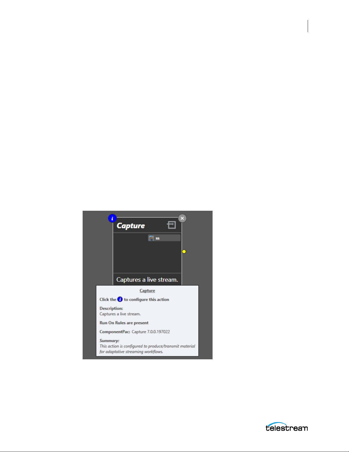
Configuring the Lightspeed Live Capture Server and Apps
Updating Capture using Secured Version Control and ComponentPacs
Updating Capture using Secured Version Control
and ComponentPacs
ComponentPacs are software libraries that do the "heavy lifting" of managing the
actions, such as Capture. ComponentPacs are part of Telestream's Secure Version
Control feature. For details, see the Secured Version Control application note on the
Telestream web site.
Secured Version Control provides the ability to install the latest software—and begin
building workflows that utilize new ComponentPac libraries, while keeping the existing
workflows untouched and operating from previous versions of a ComponentPac.
When, and if, it is desired to upgrade a workflow or action within a workflow, it can be
done at a convenient time. Secured Version Control has been implemented as part of
Lightspeed Live Capture and Vantage v7.0. ComponentPacs are architected in such a
way as to facilitate the inclusion of multiple component versions.
With Secured Version Control, it is quite easy to manage the ComponentPac versions
within workflows. When you hover over the "i" icon at the top left corner of an action,
information is displayed which includes the version of the ComponentPac library. In the
following image, the Capture action's ComponentPac is shown as "Capture
7.0.0.197022".
97
For more information see the Secured Version Control application note on the
Telestream web site.
Lightspeed Live Capture User Guide
Page 98
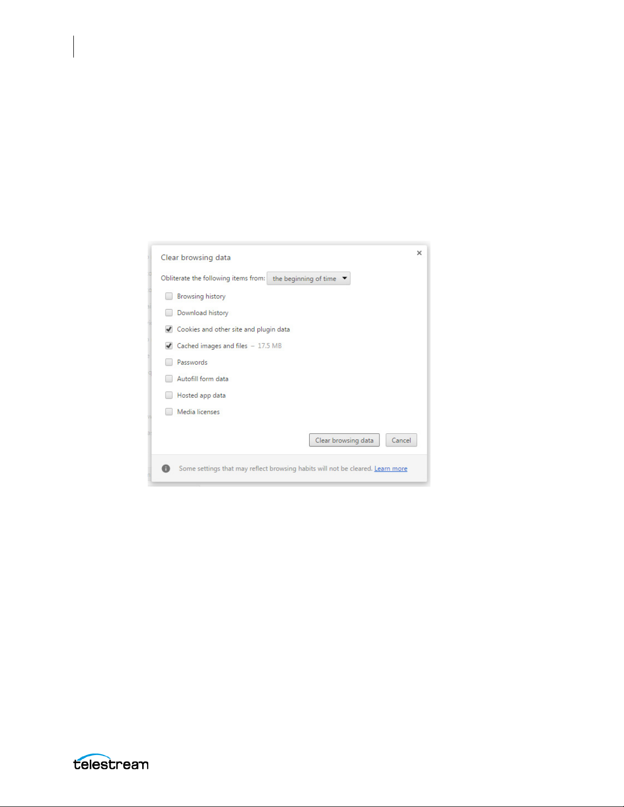
98
Configuring the Lightspeed Live Capture Server and Apps
Clear Browsing Data after Updating Vantage or Live Capture
Clear Browsing Data after Updating Vantage or
Live Capture
After a Vantage or ComponentPac update is installed, you must clear the browsing data
in your Chrome browser in order for the Lightspeed Live Capture or Tape Capture web
applications to operate properly.
Follow these steps to clear the browsing data:
1. In Google Chrome click the “Customize and Control” icon, select the “More Tools”
menu and choose “Clear browsing data...”. The Clear browsing data options appear.
2. In the Clear browsing data options select “The beginning of time” from the dropdown menu, then place a check-mark in “Cookies and other site and plugin data”,
and “Cached images and files”.
3. Click the “Clear browsing data” button.
Your browser should now be ready to operate properly with the new update.
Lightspeed Live Capture User Guide
Page 99

Creating Capture & Tape Action Workflows
This chapter describes how to create, configure, and activate the Lightspeed Live
Capture and Tape action workflows.
For additional details, open the application help (M) or the Vantage Help menu (?) from
the upper right corner of the action inspector.
99
These topics are included:
■ Additional Information
■ Creating and Activating the Capture Action Workflow
■ Creating Avid Workflows
■ Creating and Activating the Tape Action Workflow
■ Binding Variables to Configuration Parameters
■ Enabling Open Workflows
Additional Information
The following additional resources provide information about topics related to creating
and using Capture, Avid, and Tape action workflows. You may want to refer to these
resources as you use this chapter:
• Using the Live Capture Web Application
• Appendix B: Containers, Codecs, and Vantage Actions
• Lightspeed Live Stream User Guide
• Vantage User Guide
• Lightspeed Live Capture Web API Reference
Page 100

100
Creating Capture & Tape Action Workflows
Creating and Activating the Capture Action Workflow
Creating and Activating the Capture Action
Workflow
Before you can use the Capture web interface or API to produce recordings, you must
create and activate one or more capture workflows, each of which uses the Capture
action to make a video source available for Capture interface or API control.
The following topics explain how to configure the Capture action and workflows:
■ Capture Action Overview
■ Program
■ Expected Labels
■ Trigger Settings
■ Using the Schedule Trigger
■ Primary and Secondary Outputs
■ Creating a Capture Action Workflow
Lightspeed Live Capture User Guide
 Loading...