

Page 1
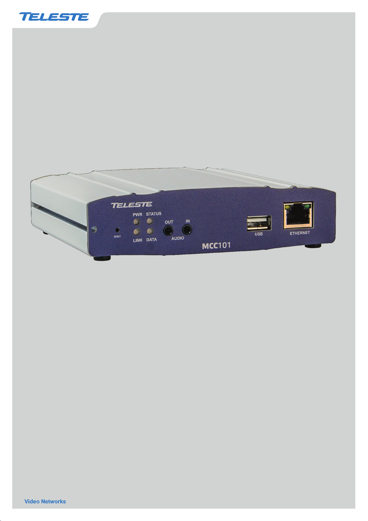
User manual
264 Encoder/decoder
operation
troubleshooting tips.
MCC101 User manual, 59300506, rev001
MCC101 H.
This manual provides information
of the MCC101, as well as
on
installation
setup and
Page 2

Page 3

MCC101 User manual
1. Introduction • I
Safety Precautions
Make sure the power is turned off before installing MCC101.
Make sure to use the product within the temperature range stated in the specification.
A recommended installation location is an indoor environment with dry and dust-free
conditions.
Ensure that the cooling air flow around the product is not prohibited.
Do not operate the product in presence of heavy electrical machinery or strong magnetic
fields.
Do not open the cover of the product in any circumstances.
Make sure that voltage is correct voltage before connecting the power on.
Page 4

II • 1. Introduction
MCC101 User manual
1. Introduction
2. Installation
3. System Operation
4. Remote Configuration
5. Decoder Configuration
6. Appendix
Table of Content
About this manual ............................................................................................................... 1
Features............................................................................................................................. 1
Product and Accessories ...................................................................................................... 2
System Connections ............................................................................................................ 5
Remote Video Monitoring ................................................................................................... 11
Initialization of IP address ................................................................................................... 15
System Configuration ......................................................................................................... 17
Video Configuration ........................................................................................................... 21
Audio Configuration ........................................................................................................... 27
Network Configuration ........................................................................................................ 29
........................................................................................................................... 1
............................................................................................................................ 8
................................................................................................................. 11
........................................................................................................... 16
Serial Configuration ........................................................................................................... 36
Event Configuration ........................................................................................................... 39
Preset Configuration .......................................................................................................... 44
Record Configuration ......................................................................................................... 45
User Configuration ............................................................................................................ 52
System Configuration ......................................................................................................... 54
Video Configuration ........................................................................................................... 55
Network Configuration ........................................................................................................ 56
Event Configuration ........................................................................................................... 58
Display Configuration ......................................................................................................... 59
............................................................................................................................ 60
.......................................................................................................... 54
Page 5

MCC101 User manual
1. Introduction • 1
1. Introduction
About this manual
This User Manual provides information on installation setup and operation of the MCC101, as well as
troubleshooting tips.
Features
MCC101 is a video and audio transmission system that provides broadcast quality audio and video, based on
IP networking. MCC101 can be operated either as an Encoder or as an Decoder, the desired mode is userselectable.
Video
Highly efficient compression algorithm, H.264 & MJPEG support
Wide range of transmission rates: 32kbps ~ 10mbps (primary stream)
Various bit rate modes: CBR, VBR
Built-in motion detection
Audio
Multi-Transmission Mode : Unidirectional Mode (IP-server to Client PC or Decoder / Client PC or
Decoder to IP-server), Bi-directional Mode
Network
Fixed IP & Dynamic IP (DHCP) support
1:1, 1:N support
Multicasting
Automatic transmit rate control according to network conditions
OnVIF, PSIA compliant
Serial Data
RS-232 support
RS-422 (4-w) or RS-485 (2-w) support
Data pass-through mode : Serial data communication between Encoder - Decoder
Page 6

2 • 1. Introduction
MCC101 User manual
Sensor and Alarm
Support direct connections of external sensor and alarm devices
Event Alarm
USB
Connection to internal or external USB storage for remote access, recording and playback
User Interface
System configuration using Internet Explorer
High Reliability
Reliable embedded system
System recovery by dual watch-dog functions
Product and Accessories
MCC101 User Manual Power adapter and Cable
Page 7
MCC101 User manual
1. Introduction • 3
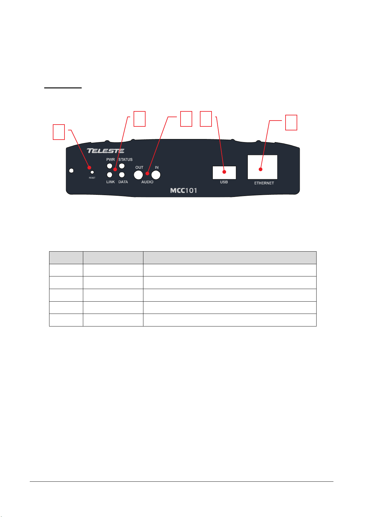
Part Names and Functions
Front View
2 3 4
1
5
Position Description Function
1 Reset button Initialization of network setting
2 LEDs Display power On/Off condition, Link, Status and data
3 Audio In, Out Audio Input and Output, for 3,5 mm stereo jack
4 USB USB port for external recording purposes
5 LAN (Ethernet) 100/10Base-T Ethernet interface, RJ-45
Page 8
4 • 1. Introduction
MCC101 User manual
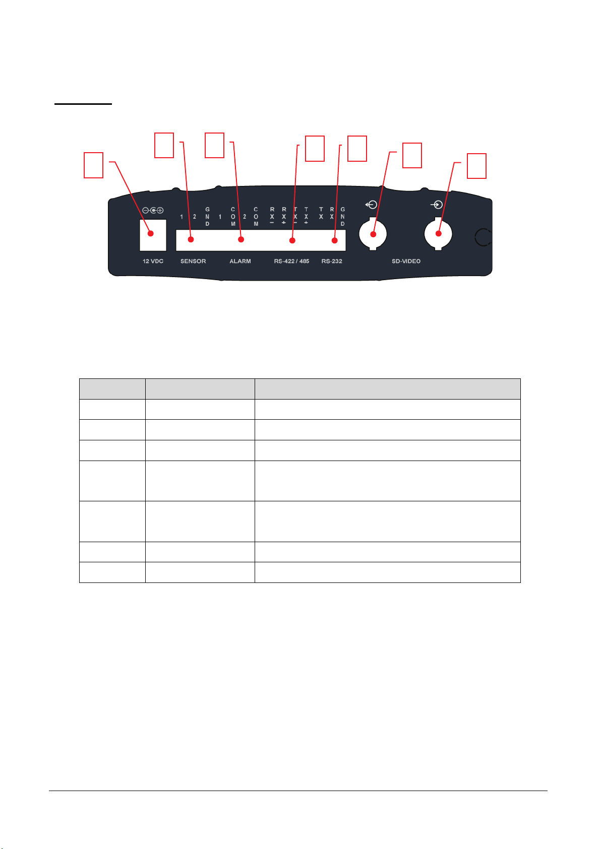
Rear View
1
2 3
4 5
6
7
Position Terminal Function
1 POWER IN DC 12V power input
2 SENSOR Sensor input, screw terminal block
3 ALARM Relay output, screw terminal block
Serial port 2 (COM2) for PTZ control and etc. Support
4 RS-422/485 (COM2)
5 RS-232 (Com1)
6 VIDEO OUT Video output, BNC
7 VIDEO IN Video input, BNC
RS-422 and RS-485 protocol, screw terminal block
Serial Port 1 (COM1) for PTZ control and etc. Support
RS-232 protocol, screw terminal block
Page 9

MCC101 User manual
1. Introduction • 5
Site
System Connections
MCC101 operates as one of the two modes; as Encoder or Decoder. MCC101 units can be connected in
either 1-to-1 fashion where one encoder is connected one decoder or 1-to-many fashion where one encoder is
connected to many decoders.
Following chart shows data status of video, audio and serial data on each mode.
System Mode Video Audio Serial Data
Encoder Transmit Transmit/Receive Transmit/Receive
Decoder Receive Transmit/Receive Transmit/Receive
Therefore, the system modes are defined by the video communication and all system modes are capable of
bi-directional transmission of audio or serial data.
Topology
Typically, the encoder and a decoder are connected in 1-to-1 mode. To support specific situation,
1-to-multiple connection is also supported.
1:1 Connection (Unidirectional Transmission).
Remote Center
Encoder Decoder
The most commonly used configuration is 1 to 1 connection. An encoder is installed at a site where video
images can be transmitted and a decoder is installed at a center location to receive and view the video images
on monitors. Audio and serial data are transferred in either direction.
Page 10

6 • 1. Introduction
MCC101 User manual
server
Site
Remote Center #1
Decoder
Remote Center #2
Decoder
Remote Center
Site
1:N Connection (Unidirectional Transmission).
Encoder
Decoder
Decoder
Decoder
In this configuration, a site can be monitored by many remote center locations. Number of maximum
connections are limited by the network bandwidth.
Functionally, a VMS (Video Management System) software can replace the HW decoder.
Multicast Mode
In a network supporting multicast mode, the products can be configured to Multicast mode which enables to
use the network bandwidth efficiently regardless of the number of decoders. In 1:N connection, a large
number of decoders can receive audio and video data from an encoder by using a single streaming
transmission.
Relaying
IP-
In this arrangement, video and audio can be retransmitted from a center to another center. The arrangement
is useful when the network bandwidth at the site is limited while there is more than one center wanting to
monitor the site.
Page 11

MCC101 User manual
1. Introduction • 7
Site
VMS (Video Management System)
Remote Center site
Encoder
VMS
Remote Center
Encoder Decoder
VMS
Video Management System is a server based remote monitoring program to access multiple encoders for
real-time monitoring or control of the encoders and connected cameras. A typical integration to VMS system is
done via OnVIF interface.
Page 12

8 • 2. Installation
MCC101 User manual
2. Installation
Connecting Video
Encoder System
Connect the camera video output (analogue composite video) to the encoder video input port.
Decoder System
Connect a monitor to the video output (analogue composite video) port accordingly.
Connecting Audio
Audio is full-duplex. Alternative operation modes are Tx-only, Rx-only or Tx-Rx.
Connect audio input and output ports to the audio devices accordingly.
Audio signal provided on a line level (+4 dBu), so audio equipment with an amp, mixer or other amplifier
should be used.
Connecting Serial Ports
For camera control, a PTZ controller (keyboard) and a receiver can be connected to the serial ports. Two
corresponding serial ports in encoder and decoder which are connected in 1-to-1 fashion works as in passthrough mode. This means that commands at a local system’s COM1 port will be transparently passed to the
remote system’s COM1 port. Also, a command at a local system COM2 port will pass to the remote system’s
COM2 port.
Connecting Sensor and Alarm
Connect sensor and alarm devices to corresponding terminals accordingly.
Connecting Power
After confirming the proper power source, connect the mains adaptor to the AC line and connect the 12VDC
connector to the MCC unit.
Page 13

MCC101 User manual
2. Installation • 9
PWR
OFF
Green
PWR
STATU S
LINK
Green
DATA
Check the system start-up
Once the power is supplied to the product, it will start booting. The system will boot up to an operating mode
after approximately 40 - 60 seconds. The green LED on the Ethernet port will flash indicating the system is
ready.
Encoder LED displays
STATUS
LINK DATA
Red
Blinking
OFF
These LEDs show that the camera is connected but a decoder is not connected.
Once the encoder is connected to a decoder, color of “LINK” LED will turn into green color. “ DATA” LED will
blink while video or audio transmission is detected.
Decoder LED displays
Red
Blinking
OFF
These LEDs show that the Decoder has started without connection to an encoder. Once an encoder is
connected, the color of “LINK” LED will be turned to green. “DATA” LED will blink while video or audio data
transmissions is detected.
Page 14

10 • 2. Installation
MCC101 User manual
Description of LEDs
System status can be monitored by following indications.
LED State Description
Off Power off
PWR
Red Power on
Green blinking Normally operating
Red System failure: Needs diagnostics
STATU S
LINK
Constant change of colors between
Red and Green
Red blinking Failed to obtain IP address in DHCP mode
Constant change of colors
between Green blinking 2 times
and Red blinking once
Green blinking, Red blinks
once every 5 seconds
Constant change of colors:
Green, Orange, Red color in turn
Off No connection to remote system
Green Connected to a remote system
Red blinking Decoder only: trying to connect to an Encoder
Orange
Green Data transmission in progress
NTSC/PAL setting does not match with input video
signal
Failed to register on DDNS server
Video loss in Encoder system
Formatting USB storage device
Illegal connection
(unsupported combination of system modes)
DATA
Red Data loss
Off No data transmission
Page 15

MCC101 User manual
3. System Operation • 11
3. System Operation
Remote Video Monitoring
There are two ways to monitor video when the center system and MCC101 are connected. In order for
a proper operation, an IP address must be set accordingly.
Default ID: admin Default Password: 1234
Video Monitoring with Decoder System
Once the encoder IP address is set in the remote IP address section of the decoder, the decoder system will
connect to the encoder system and start receiving the video stream. Normally, a monitor connected to the
decoder will display video images.
Page 16
12 • 3. System Operation
MCC101 User manual
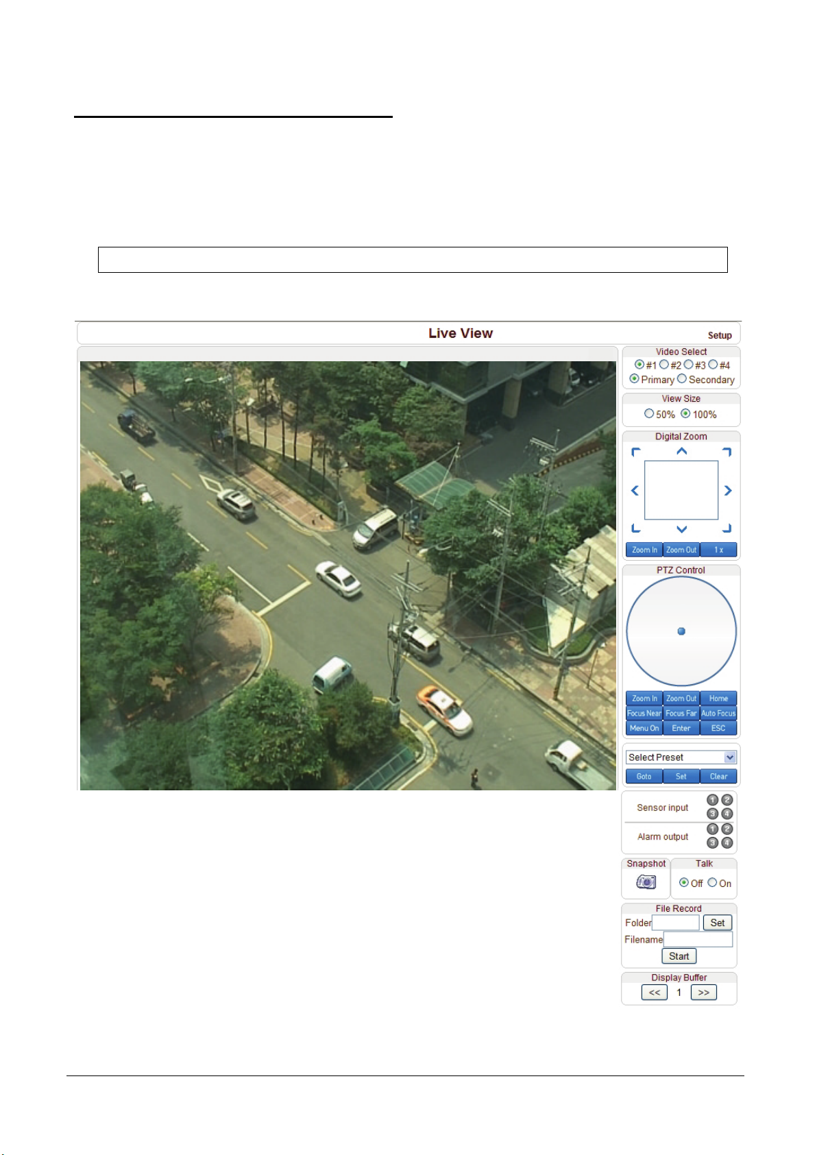
Video Monitoring using Internet Explorer
If MCC101’s IP address in entered on the Internet Explorer, the system will ask for confirmation to install an
Active-X control (Teleste ActiveX Control, Publisher is Teleste Corporation). Once authorized, the Internet
Explorer will start to display video images from the encoder as shown below.
Default IP Address: http://192.168.10.100
Page 17

MCC101 User manual
3. System Operation • 13
Video Select
Select the Video stream to be viewed: Primary or Secondary
This camera is capable of dual streaming; primary streaming and secondary streaming.
Video will be displayed according to the resolution set on video configuration. If dual streaming
(“Use Dual Encode” Menu in Video page) is not activated, secondary video is not available.
View Size
Adjust the Screen size
Screen size is initially adjusted according to the compression resolution. If you click 50% icon,
the whole screen size will be reduced to half size.
Digital Zoom
Control the Digital zoom on the screen
The more the camera zooms in, the smaller the square of control panel is.
Position of the image can be changed by moving position of the square.
If you press x1, the screen will return to the normal size.
PTZ Control (Optical Zoom & Digital zoom built-in the camera)
Control PTZ and PTZ Control Panel is used for controlling external PTZ devices
when the external PTZ devices are connected through serial port.
It is possible to make zooming control by Zoom in/out buttons of PTZ control Panel
(In order to use digital zoom, select Digital zoom ON in the Camera tab)
- Stop
Stop on-going PTZ action.
- Focus Near, Focus Far, Auto Focus
Adjust the focus of the lens.
Select Preset
Set preset position and move to the specific preset position.
- Goto: Move to the selected preset entry if the preset entry is set.
- Set: Set the current position to the selected preset entry.
- Clear: Delete the selected preset entry.
Sensor Input
Display the status of the sensor in real time.
This camera supports one sensor input. When the sensor of the camera is working, the sensor light
turns red.
Page 18
14 • 3. System Operation
MCC101 User manual
Alarm Output
Operate the alarm device by pressing the number icon.
This camera supports one alarm output. A number icon indicates status of the alarm device.
Snapshot
Capture video images and store them as BMP or JPEG files.
Talk
Transfer audio from PC’s mic to the camera.
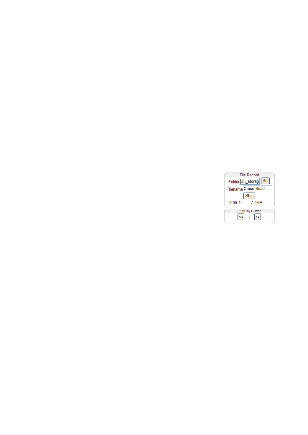
File Record
Recording to an AVI file on Live View page is available. AVI files are generated in the specified folder
or in specified file name on the PC where web browser is running.
1. Press “Set” button to select folder or create a new folder. Enter the file name on Filename field.
2. Press “Start” button to start to record.
3. Press “Stop” button to stop to record.
4. AVI file named “IP address_hh_mm_ss” or “File name_IP
address_hh_mm_ss” will be generated in the specified folder depending on
whether the path specified a folder or a prefix of the file name.
Display Buffer
Set the number of video frames to be buffered before being displayed on web browser. Larger value
results in smoother video by sacrificing the latency. A setting of 10 ~ 15 frames can be used generally for
most situations.
Page 19

MCC101 User manual
3. System Operation • 15
•
•
•
•
•
•
Initialization of IP address
If a system IP address is lost, the system can be reset to the system default IP address using the reset button
in the back side of the system.
1. While system is in operation, press the reset button for more than 5 seconds.
2. The system will reboot automatically
3. Once the system reboots, IP address will be set to the system default as below.
IP mode Fixed IP
Subnet mask 255.255.255.0
Base port 2222
IP address 192.168.10.100
Gateway 192.168.10.1
HTTP port 80
Page 20
16 • 4. Remote Configuration
MCC101 User manual
4. Remote Configuration
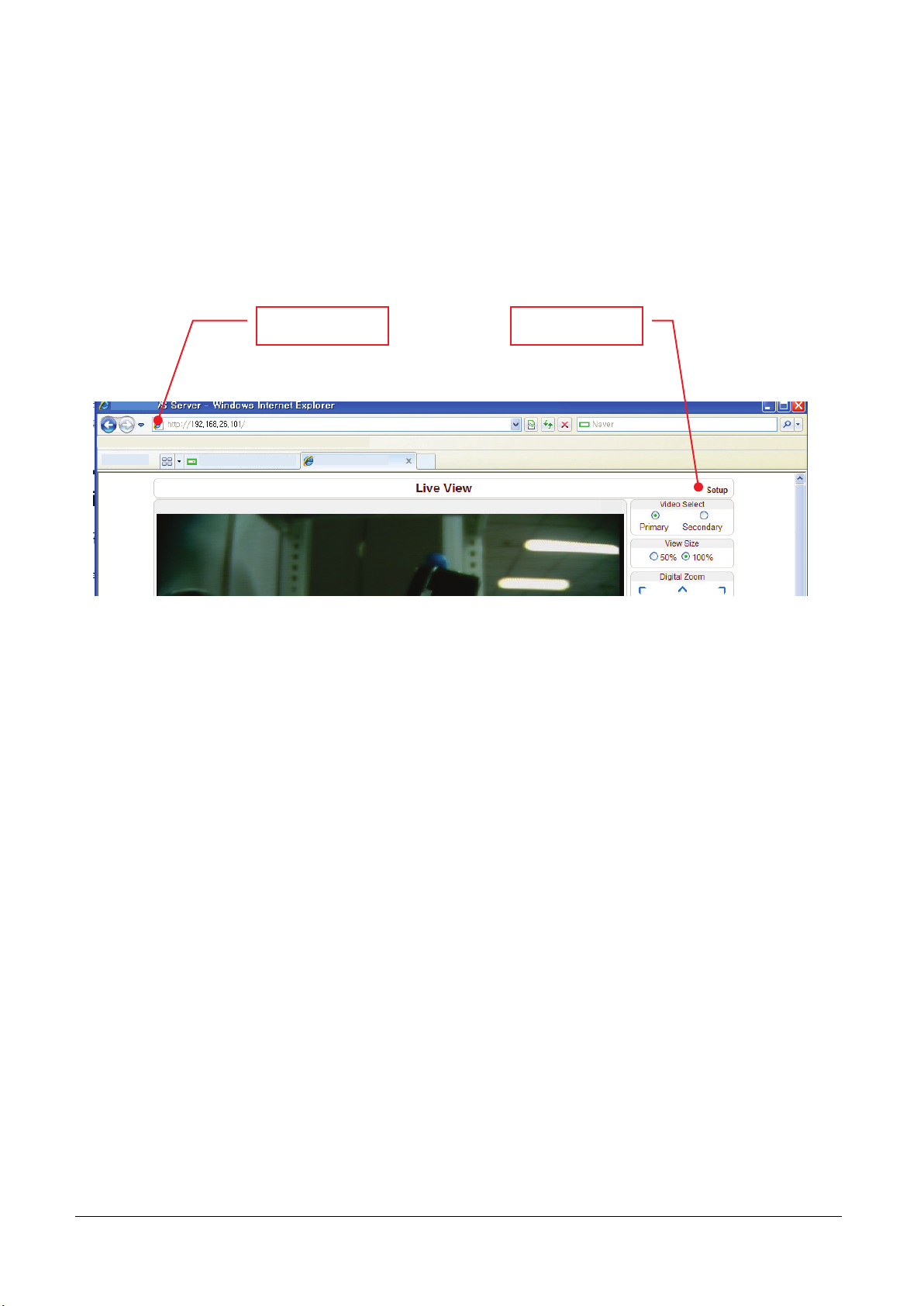
Remote setting is available by using web browser. Enter IP address of camera and then a live view screen
appears as below. Press Setup button located in the upper right area of the monitoring screen to go to the
server setup. For Remote Setting, user should be authorized higher than manager level.
Enter IP address Press Setup button
The remote configuration window may be slightly different depends on the system mode (Encoder or
Decoder). The general explanation of the configuration in this manual is based on Encoder system and
differences according to the modes will be clarified when needed.
The configurations are grouped into 10 categories: System, Video, Audio, Network, Serial, Event, PTZ,
Record, User and Camera. Any configuration changes are not applied until Apply button is pressed. Leaving
the page without pressing Apply button, any changes in the page will be discarded.
Page 21
MCC101 User manual
4. Remote Configuration • 17
System Configuration
Page 22

18 • 4. Remote Configuration
MCC101 User manual
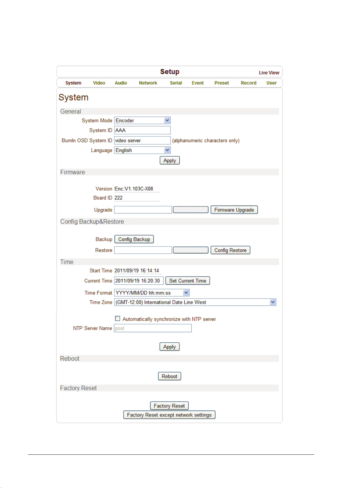
General
System ID
Enter System ID that is used as a camera title.
The set System ID is displayed with video image on Web browser.
The System ID is also transferred to remote software, such as VMS, and displayed on it.
Burnin OSD System ID
Burninin OSD System ID specifies the string to be inserted into video image before encoding.
Only alphanumeric and blank characters are allowed. Position and size can be configured on
Burnin OSD section of Video page.
Language
Select the language to be used for web-based configuration.
Firmware
Firmware version
Display the current firmware version.
Board ID
Display the Network board ID of the camera recognized by system.
Upgrade
Upgrade firmware.
1. Press Browse button to select a firmware file from PC.
2. Press Firmware Upgrade button to start to upgrade.
3. Messages for showing status (downloading / upgrading) will be displayed.
4. The camera will reboot automatically after completing upgrade.
Do not turn the camera off during upgrading
Page 23

MCC101 User manual
4. Remote Configuration • 19
Config Backup & Restore
Backup
All the setting of configuration can be stored.
Restore
Stored configuration can be browsed and restored. The server is rebooted once Config Restore
button is pressed.
Time
Start Time
The latest the camera’s booting date and time.
Current Time
Current date & time.
Enter a new date and time and press Set Current Time button to update date & time.
Time Format
Change the time format. Selectable time formats are as below.
- YYYY/MM/DD hh:mm:ss (Ex. 2010-4-11 18:18:42)
- DD/MM/YYYY hh:mm:ss (Ex . 11-4-2010 18:18:42)
- MM/DD/YYYY hh:mm:ss (Ex. 4-11-2010 18:18:42)
Time Zone
Select time zone of where the camera is installed.
Depending on the time zone, Daylight Saving Time will work automatically.
A time zone is a region of the earth that has uniform standard time, usually referred to as the local
time. By convention, time zones compute their local time as an offset from UTC (Coordinated
Universal Time). In casual use, GMT (Greenwich Mean Time) can be considered equivalent to UTC.
Local time is UTC plus the current time zone offset for the considered location.
Page 24

20 • 4. Remote Configuration
MCC101 User manual
Automatically synchronize with NTP server
Synchronize the camera time with an NTP server using NTP (network time protocol).
Name of the NTP server should be registered on NTP server Name.
The Network Time Protocol (NTP) is a protocol for synchronizing the clocks of computer systems
over packet-switched, variable-latency data networks. It is designed particularly to resist the effects
of variable latency by using a jitter buffer.
Reboot
Reboot the camera.
Do not press the Reboot button unless the server needs a reboot.
Factory Reset
All settings including user accounts and logs are cleared.
Factory Reset except network settings
All the settings except for current network settings are changed to default values.
Page 25
MCC101 User manual
4. Remote Configuration • 21
Video Configuration
Page 26

22 • 4. Remote Configuration
MCC101 User manual
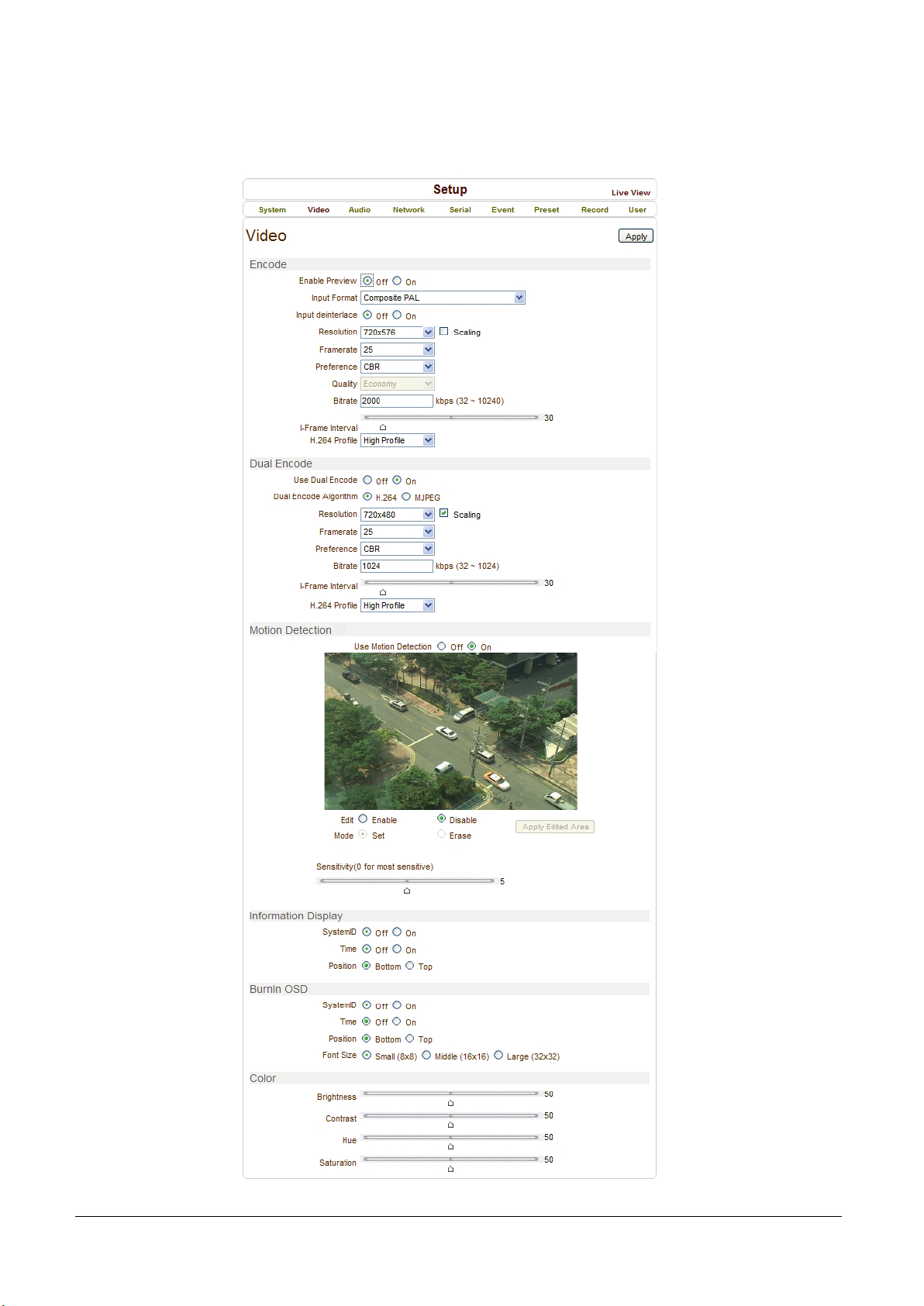
Encode
Note!: some of the features are not available until the unit is connected to video signal.
Enable Preview
1. Select ON to enable to display video on the monitor that is connected to the composite video port.
2. Select the Output format accordingly in the end of the Video page.
Note! That when Enable Preview is ON, dual streaming is not available.
When the video is transmitted directly to the monitor through BNC cable, the video does not go thorough
network and encoding. Therefore, there is less delay and no an effect from network limitation.
Input Format
Choose video type to be used between composite NTSC or composite.
Input Deinterlace
Deinterlace function is activated If selected ON.
Resolution
Select video encoding resolution.
Framerate
Determine the maximum number of frames per second for the video stream.
1,2,3,4,5,6,8,10,15,20,25 and 30 frame rate can be selected. The actual frame rate of video can be
less than the maximum frame rate set due to the network bandwidth limitation
Preference
Select encoding mode to control video quality or bitrate: Quality (VBR) or Bit rate (CBR).
If ‘Bitrate’ selected, the video encoding will be effected by the ‘Bitrate’ value entered. Therefore,
“Bitrate” mode corresponds to CBR (Constant Bit rate) encoding.
If ‘Quality’ selected, the video encoding will be effected by the quality of image selected.
Therefore, “Quality” mode corresponds to VBR (Variable Bit Rate) encoding.
Quality
Select Video quality. 7 levels of quality are available.
Quality mode (VBR encoding) tries to encode every frame in a constant quality. Therefore, resulting
bitrate may vary a lot depending on the complexity or activity changes in the input video. It is preferred
when constant video quality is required and network bandwidth is enough for delivering the stream of
highly varying bitrate.
Page 27

MCC101 User manual
4. Remote Configuration • 23
Bit rate
Determine bitrate value between 32 ~ 10240kbps.
Bitrate mode (CBR encoding) allows you to set a fixed target bitrate that consumes a predictable
amount of bandwidth. In order to keep the bitrate limit, video quality is controlled dynamically according to
the complexity or activity changes in the input video.
I-Frame Interval
Determine I-frame Interval between 1 and 255.
H.264 Profile
Select H.264 Profile: High Profile or Baseline Profile
The standard defines various sets of capabilities, which are referred to as profiles, targeting specific
classes of applications.
- High Profile (HiP)
The primary profile for broadcast and disc storage applications, particularly for high-definition television
applications (for example, this is the profile adopted by the Blu-ray Disc storage format and the DVB
HDTV broadcast service).
- Baseline Profile (BP)
Primarily for low-cost applications that require additional data loss robustness, this profile is used in
some videoconferencing and mobile applications. This profile includes all features that are supported in
the Constrained Baseline Profile, plus three additional features that can be used for loss robustness
(or for other purposes such as low-delay multi-point video stream compositing).
Dual Encode
Use Dual Encode
1. Select Off button on the Enable Preview to enable to use Dual Encode
2. Select ON to enable to use Dual Encoding
The secondary video can be viewed on Live View window by selecting Secondary on Video selection
Dual Encode Algorithm
Select H.264 or MJPEG for the secondary streaming.
In case of H.264, either Bitrate mode or Quality mode can be selected for Preference mode in.
On the other hand, MJPEG supports Quality mode only.
Page 28
24 • 4. Remote Configuration
MCC101 User manual
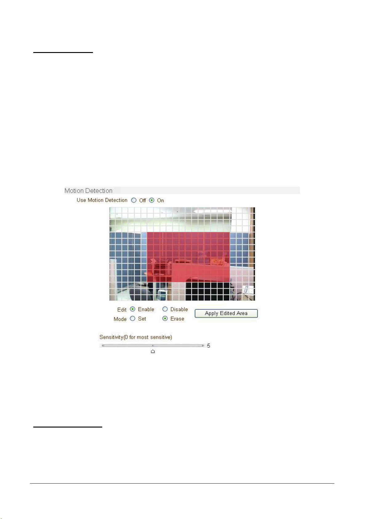
Motion Detection
Use Motion Detection
Determine to use Motion Detection function.
Motion Detection Area Editing
Configure regions for motion detection. Regions of arbitrary shape can be configured by
the following steps.
1. Select Enable on Edit tab
2. Select editing Mode. Set is for including cells to motion detection region and Erase is for excluding.
3. Select cells using the right button of the mouse. Multiple cells can be selected conveniently by press
and dragging.
4. Press Apply Edited Area to save the editing.
Sensitivity
Sensitivity is the condition to trigger an event of motion detection.
The value determines the sensitivity of the motion detection within a block: the smaller, the more sensitive.
It is selectable from 0 to 10.
Information Display
System ID and/or server time can be display over the video window in Internet Explorer. Each item can be
turn on or off separately, and position also can be configured. This information is displayed after the video
is decompressed.
Page 29

MCC101 User manual
4. Remote Configuration • 25
BurnIn OSD
Insert system ID and date/time in the compressed video. System ID and time respectively can be turned on
or off in the video. Position and Font size can be configured also. System ID for BurnIn OSD exists
independently from normal System ID.
Note! That size of Burnin OSD display varies according to the encoding resolution setting. This is inevitable
because Burnin OSD is inserted to the frames before encoding is performed. The following table describes the
rule for BurnIn OSD display.
Resolution Small (8x8) Middle (16x16) Large (32x32)
352x480 / 352x240 / 352x576 / 352x288 2 1 0
720x480 / 720x240 / 720x576 / 720x288 /
640x480 / 800x600
1024 x 768 / 1280x720 / 1280 x 960 / 1280x1024 /
1440x900 / 1600x900 / 1680x1050 / 1920x1056 /
1920x1080 / 2048x1536 / 2560x1600 / 2592x1936
2 : Both System ID and Time are displayed.
1 : Either System ID or Time can be displayed. When both are enabled, System ID is displayed.
0 : No items are displayed. This is because video area is too small to display OSD text in large text.
Color
Adjust the color properties of input video: brightness, contrast, hue, saturation.
2 2 1
2 2 2
Video Enhancement
3D Combo Filter
Eliminates color interference in very dense graphic patterns. Also improves color separation
and image sharpness.
3D Noise Reduction
- Achieves up to 38% data rate reduction
- Sharper image details and less visible noise
- Requires No additional CPU processing power
Page 30

26 • 4. Remote Configuration
MCC101 User manual
3D De-interlace Mode
Restores lost lines caused by video interlacing – no more jaggy edges, missing segments, or distorted
patterns.
- Off: uses interlace mode
- VT Filter: If scaling-down is used, the total number of active pixel per line is scaling pixel resolution and
enlarging the blaing area to meet ITU-R 656 horizontal line timing.
- Field Merge: Converts “Progressive Video Frame” to ITU-R BT.656 standard transmission.
- Line Double: The “Odd”(or “Even”) field of ITU-R BT.656 output is constructed by taking the Odd
(or Even) line of NTSC(PAL) de-interlacing progressive video frame.
WDR Mode (Wide Dynamic Range)
- Widens perceivable luminance range by boosting visibility of dark areas without saturation bright areas
- Suitable for backlit and dark environments
- Adaptive real-time hardware algorithm that maintains natural color balance and sharp edges
De-mist Mode
- Designed for particle-degraded image conditions; mist, fog, smoke, rain, snow, dust storm, hail,
undersea, etc.
- Adaptively analyzes and restores contrast and color information buried in pale and washed-out images.
Page 31
MCC101 User manual
4. Remote Configuration • 27
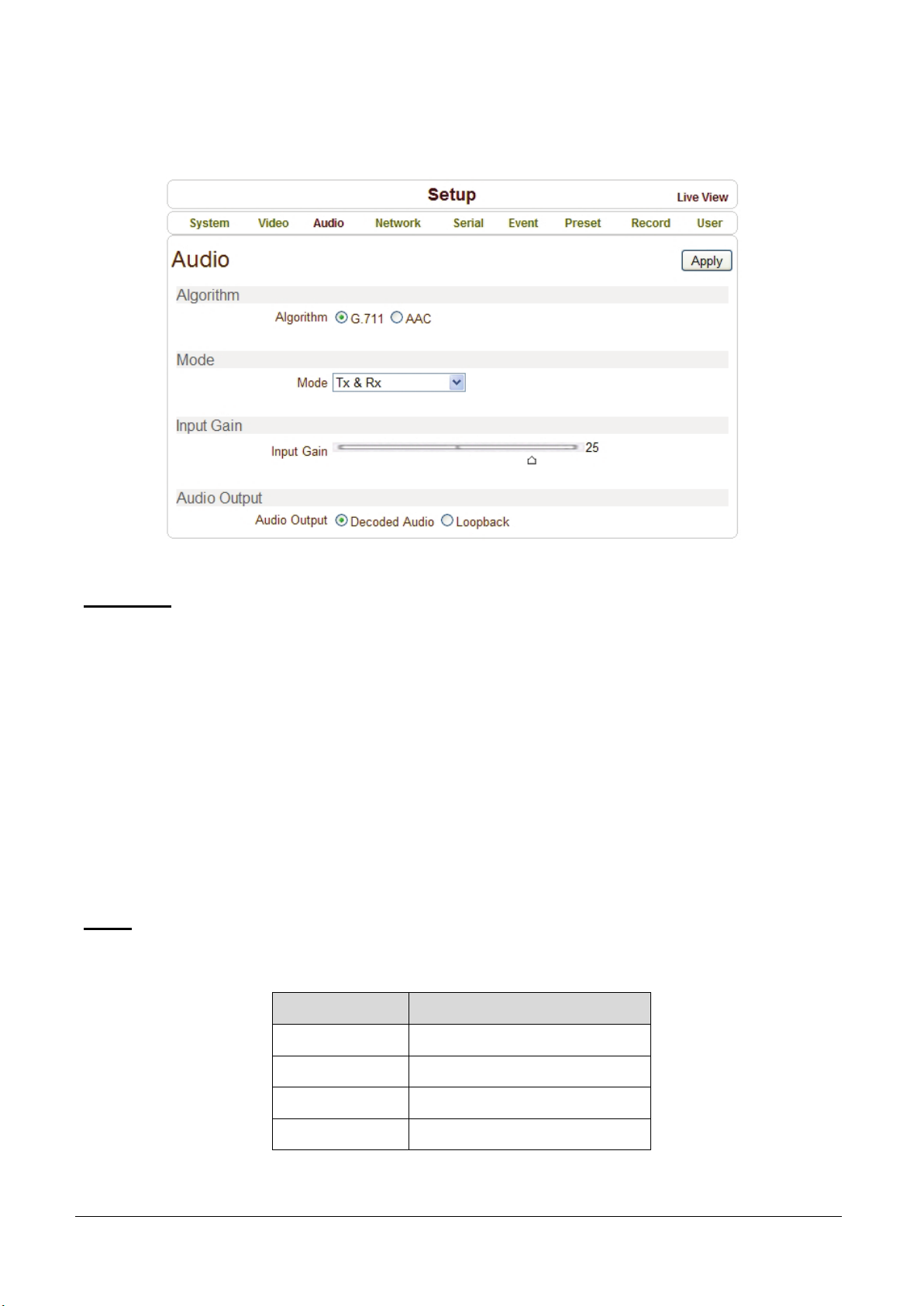
Audio Configuration
Algorithm
Algorithm
Select the audio algorithm: G.711 or AAC.
G.711 and AAC from client to server direction are supported. Thus, bidirectional audio communication
is supported.
Bit rate
Select the bitrate between 64Kbps and 128kbps when AAC is selected.
The sampling rate is fixed to 8KHz and 32KHz for G.711 and AAC respectively.
Note that when camera is connected to a decoder, the decoder’s audio algorithm should be set identically
to transmit audio properly.
Mode
Select audio operation mode:
Mode Action
Off No operation
Tx - Only Transmit only
Rx - Only Receive only
Tx & Rx Transmit and Receive
Page 32

28 • 4. Remote Configuration
MCC101 User manual
Input Gain
Set audio input gain from 0 to 31.
Audio Output
Configure the audio source to be played on audio output port.
Decoded Audio: Audio stream from client is played.
Loopback: Audio data from audio input port is loop-backed to the audio output port.
Page 33
MCC101 User manual
4. Remote Configuration • 29
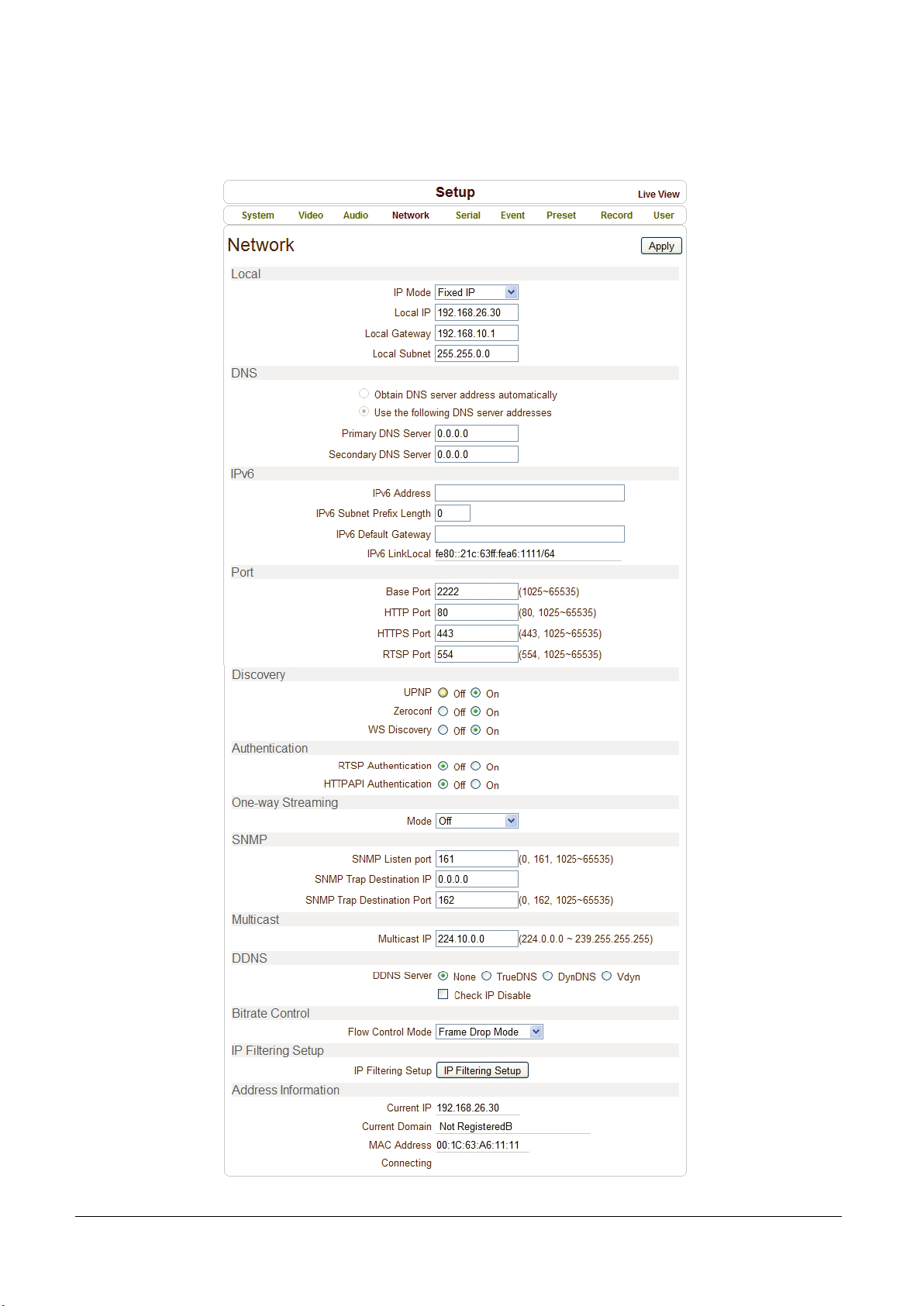
Network Configuration
Page 34

30 • 4. Remote Configuration
MCC101 User manual
Local
IP mode
Select the IP mode: Fixed IP or DHCP (Dynamic Host Configuration Protocol).
Depending on the selected mode, further configuration items come as follows:
IP Mode Selection Description
Local IP Fixed IP address
Fixed IP
DHCP
☞ Please ask IP address information from ISP provider or network manager.
Local Gateway Gateway IP address
Local Subnet Subnet mask
N/A
DNS
Obtain DNS server address automatically
Get DNS server address automatically when IP mode is DHCP.
Use the following DNS server addresses
Enter the DNS server IP address.
- Primary DNS server
- Secondary DNS server
Domain Name System (DNS) is a database system that translates a computer's fully qualified
domain name into an IP address. Networked computers use IP addresses to locate and connect to
each other, but IP addresses can be difficult for people to remember. For example, on the web, it's
much easier to remember the domain name www.amazon.com than it is to remember its
corresponding IP address (207.171.166.48). Each organization that maintains a computer network.
will have at least one server handling DNS queries. That server, called a name server, will hold a list
of all the IP addresses within its network, plus a cache of IP addresses for recently accessed
computers outside the network.
Page 35

MCC101 User manual
4. Remote Configuration • 31
Ipv6
Ipv6 Address
Enter the designated Ipv6 address.
Ipv6 Subnet Prefix Length
Enter the bit number of Ipv6 Subnet.
Ipv6 Default Gateway
Enter the designated Ipv6 gateway.
Ipv6 Link Local
Display Ipv6 Link Local.
Port
Base Port (1025 ~ 65535)
Enter the Base Port number.
Network base port is use for communication with remote clients. In order for camera and remote systems
(decoder or VMS, NVR software) to be connected, the port number must be identically configured in
camera side and client side.
HTTP Port (80, 1025 ~ 65535)
Enter HTTP port used for web-based connection.
HTTPS Port (443, 1025 ~ 65535)
Enter HTTPS port used for secured HTTP connection.
RTSP Port (554, 1025 ~ 65535)
Enter RTSP port used for RTSP-based connection. The default RTSP port is 554.
RTSP (Real Time Streaming Protocol) is a standard for media streaming between server and client.
Discovery
UPNP
By setting UPNP to ON, it allows the discovery by the client according to UPNP (Universal Plug and Play)
protocol.
Zeroconf
By setting Zeroconf to ON, it allows the discovery by the client according to Zeroconf protocol.
Page 36

32 • 4. Remote Configuration
MCC101 User manual
WS Discovery
Discovery function based on web service is enabled. It allows the discovery by Client SW which is
supporting Onvif.
Authentication
RTSP Authentication
If RTSP Authentication set to ON, user in the client side is asked to enter User ID and Password.
HTTP API Authentication
When HTTP API authentication set to ON, HTTP Authentication is asked for all clients which use HTTP API.
One-way Streaming
This unit provides two kind of one-way (unidirectional) streaming based on UDP to clients: RTP and
MPEG-TS. Both are a kind of broadcasting where traffic from client to server is not generated at all.
RTP (Real-Time Transport Protocol) is an Internet protocol used for transmitting single real-time
multimedia data such as audio and video to a select group of connected clients. Normally RTSP uses
RTP to format packets of multimedia content. RTP menu is used when the RTP only streaming without
RTSP connection. RTP stream will be transmitted to the destination set. The SDP (Session Description
Protocol) file can be found in the server, and a client can retrieve it using http connection.
Related settings are as follows:
- Destination IP: Set the IP Address of the destination system which will receive RTP stream.
If the system is decoder, RTSP authentication information can be entered in the middle of RTSP URL
as follows:
rtsp://admin:[email protected]:554/video1
- Destination Port: Set the Port of the destination system which will receive RTP stream.
- User Name: Enter the User name that will be used as session name in the SDP file.
- File Name: Enter the file name that will be used as the name of the SDP file.
Then, it can be accessed through http://ServerAddress/filename
Page 37
MCC101 User manual
4. Remote Configuration • 33
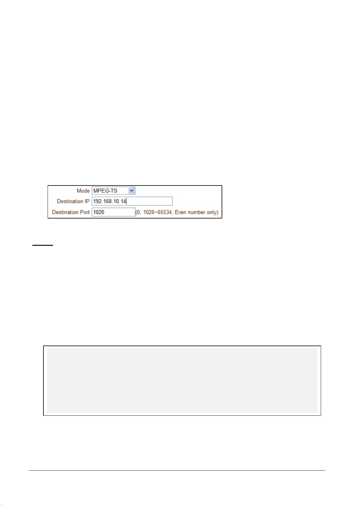
MPEG-TS is a standard format for transmission and storage of audio, video, and data, [7] and is used in
broadcast systems such as DVB and ATSC. Transport Stream is specified in MPEG-2 Part 1, Systems
(formally known as ISO/IEC standard 13818-1 or ITU-T Rec. H.222.0). Transport stream specifies
a container format encapsulating packetized elementary streams, with error correction and stream
synchronization features for maintaining transmission integrity when the signal is degraded.
As MPEG-TS itself supports only AAC as the audio algorithm, only video is streamed when audio
algorithm is set to G.711.
Related settings are as follows:
-
Destination IP: Set the IP Address of the destination system which will receive MPEG-TS stream.
-
Destination Port: Set the Port of the destination system which will receive MPEG-TS stream.
SNMP
Setup for using SNMP (Simple Network Management Protocol). It is compatible to both SNMPv1 and
SNMPvec. Settings for using SNMP (Simple Network Management Protocol) are as following:
SNMP Listen Port(0, 161, 1025 ~ 65535): The port is for connecting external devices when system
operates as a SNMP client. SNMP is not used by setting 0 value.
SNMP Trap Destination IP: Set the SNMP Trap Destination IP.
SNMP Trap Destination Port (0, 162, 1025 ~ 65535): Set the SNMP Trap Destination Port. SNMP is not
used by setting 0 value.
Simple Network Management Protocol (SNMP) is used by network management systems to
communicate with network elements. SNMP lets TCP/IP-based network management clients use a
TCP/IP-based internetwork to exchange information about the configuration and status of nodes.
SNMP can also generate trap messages used to report significant TCP/IP events asynchronously to
interested clients. For example, a router could send a message if one of its redundant power supplies
fails or a printer could send an SNMP trap when it is out of paper.
Page 38

34 • 4. Remote Configuration
MCC101 User manual
Multicast
Multicast IP
The Multicast menu is used for configuring the multicast IP address to which media stream is delivered
when a client such as a Decoder, VMS or NVR software is connected in multicast mode. The multicast IP
address selection range is between 224.0.0.0 and 239.255.255.255. The selection can be used only
when media protocol is set to Multicast.
DDNS
Recommended setting is none.
Dynamic DNS is a method, protocol, or network service that provides the capability for a networked
device, such as a router or computer system using the Internet Protocol Suite, to notify a domain
name server to change, in real time (ad-hoc) the active DNS configuration of its configured
hostnames, addresses or other information stored in DNS.
Check IP Disable: If “Check IP Disable” is selected, it will skip to check its own IP. In Fixed IP mode, the
set IP will be registered on DDNS server. In DHCP mode, dynamically assigned IP will be registered on
DDNS server. Normally Check IP Disable should be unchecked in order to obtain public IP in the network.
Page 39

MCC101 User manual
4. Remote Configuration • 35
Bitrate control
When there are more than one client connected to the camera, due to bandwidth difference among the clients
some of them do not have enough bandwidth to receive encoded stream completely. In this case, it is possible
to select the way to stream video to clients as following.
- Frame Drop Mode: Encoding is performed strictly according to video settings. When a client is
connected through a network with less bandwidth, it may not receive all the frames. That is, frames are
dropped on sending module if the network is bottlenecked.
- Suppression Mode: Encoding bitrate and frame rate are adjusted not to drop any frames when the
network bandwidths to some clients are limited. In this case, all clients can be affected by the averaged
bitrate and frame rate.
Address Information
Followed network information is displayed (Read only).
IP Address: The Camera own IP address. This information is useful when the camera’s IP mode
is set to DHCP.
Domain Name: In case the camera is registered at DDNS server, the registered domain name is
displayed.
MAC Address: Display the MAC address of the camera. In case the camera is registered at DDNS
server, the MAC address is used in DDNS registration.
Connecting: Client IP Addresses that are currently connected to system are listed. (1) Indicates.
Page 40
36 • 4. Remote Configuration
MCC101 User manual
Serial Configuration
Page 41

MCC101 User manual
4. Remote Configuration • 37
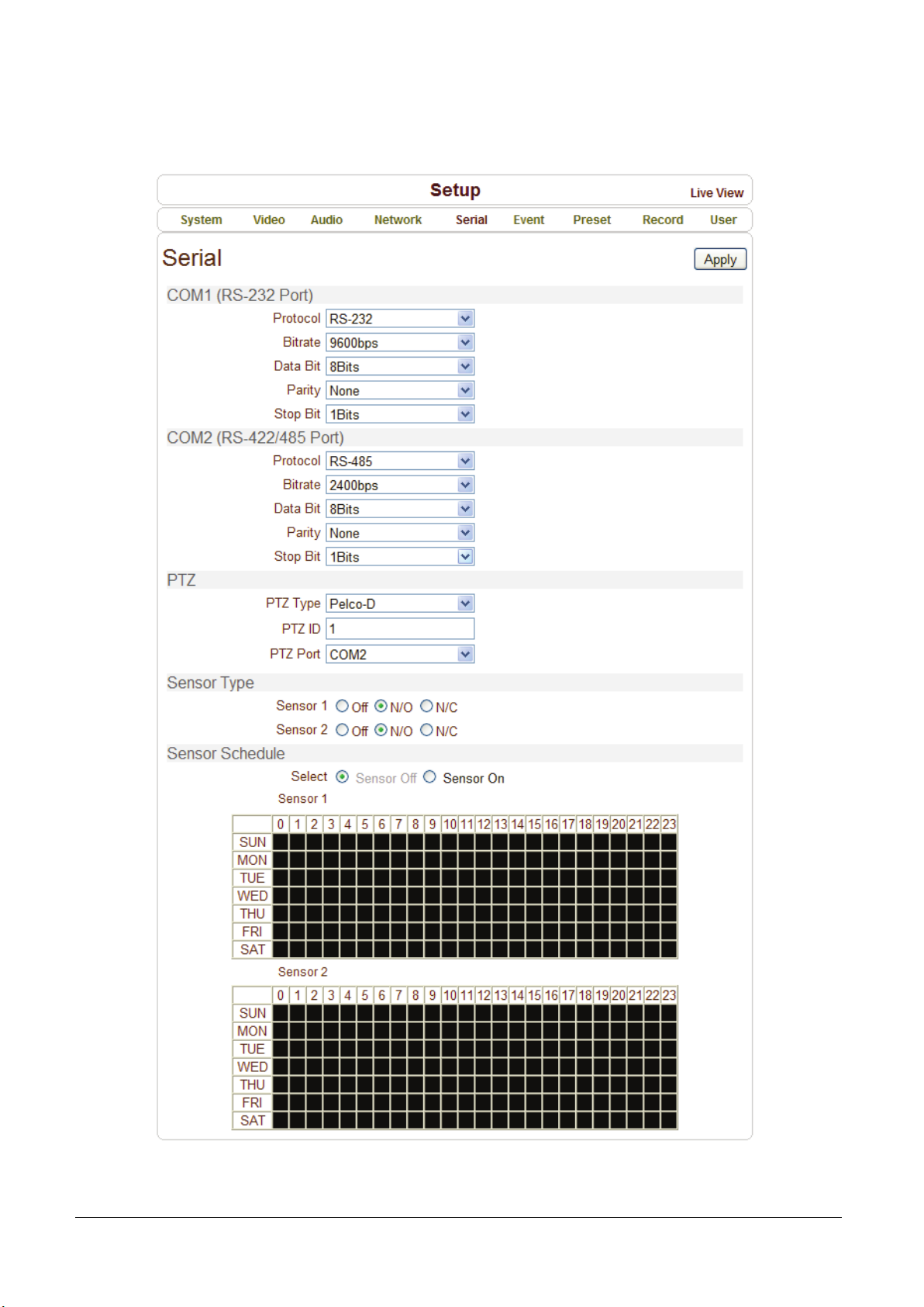
Serial Port Configuration
Serial Protocol: There are two serial ports, RS-232, RS-422/485 in MCC101.
Select RS-422 or RS-485 in RS-422/485 port.
Serial Port Configuration: The serial ports can be configured as follows.
Note!
Each of the serial ports configurations must be same as the connecting device.
Mode Selection
Bitrate 2400, 4800, 9600, 19200, 38400, 57600, 115200 bps
Data Bits 5, 6, 7, 8 bits
Parity NONE, EVEN, ODD bit
Stop Bit 1, 2 bit
PTZ
PTZ Type: Select the type of PTZ camera or receiver.
PTZ ID: Since it is possible to control multiple PTZ cameras or receivers over single control line,
each camera or receiver will be assigned with unique ID. Enter PTZ ID of a camera or receiver for control.
The ID value range can be between 0 and 255.
PTZ Port: Select the serial port used for PTZ camera control.
Sensor Type
There are two sensor input ports on MCC101. Each of the sensor ports can be configured to the following.
The function of the sensor port is set based on the type of the sensor connected.
Function Operation
OFF Not used.
NO (Normally Open) The port is normally open and activated when closed.
NC (Normally Closed) The port is normally closed and activated when opened.
Page 42
38 • 4. Remote Configuration
MCC101 User manual
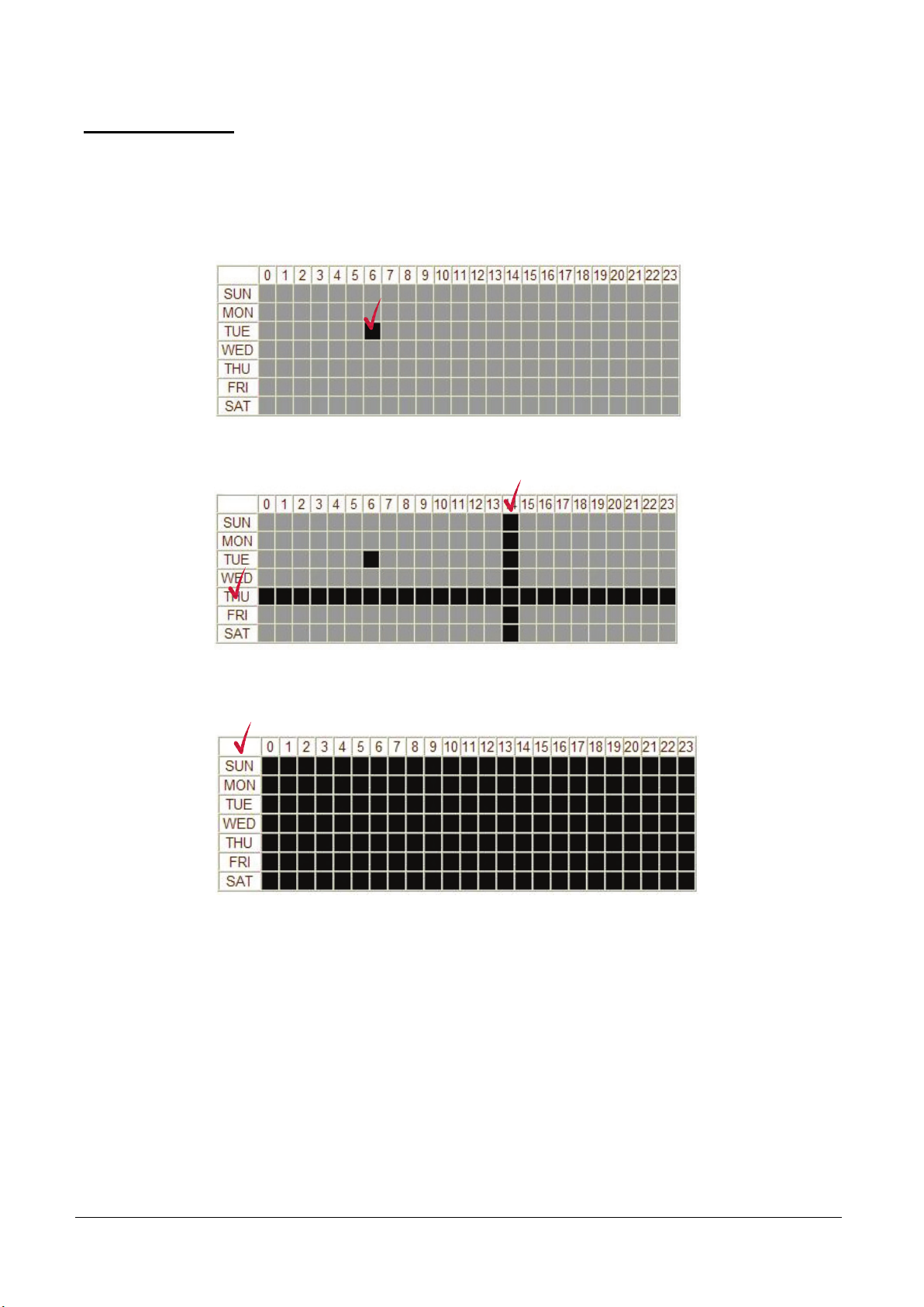
Sensor Schedule
Choose Sensor OFF or Sensor ON and click the below schedule cells to make Sensor Schedule
according to day of week and hour.
- Click desired “Cell” to set schedule.
- Click desired “Time Line or Date Line” to set schedule.
- To set cells in the schedule, click below “Empty Cell”.
Page 43
MCC101 User manual
4. Remote Configuration • 39
Event Configuration
Page 44

40 • 4. Remote Configuration
MCC101 User manual
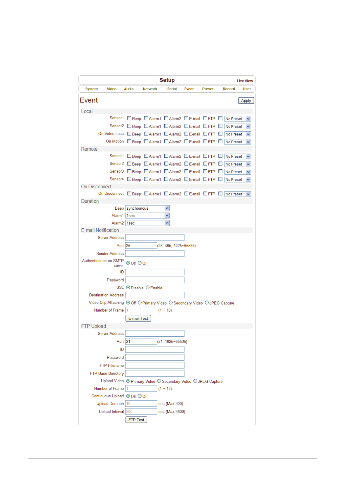
This product has two sensor ports and two alarm ports.
When a decoder instead of a PC client is connected to encoder, one system becomes a Local system and
the other as a Remote system (in general a system which is being used by the user is called as Local
system). Then, actions for events can be configured for events from the remote system as well as for local
system. For example, it is possible to turn on an alarm device in local (center) decoder system when a
sensor device in remote end (site) encoder is triggered. Local section configures the actions for events
from local (self) system, and configuration activates local devices and Remote sections configure the
actions for events from remote (peer) system.
The following table lists the possible actions for events.
Action Description
Beep Triggers beep port.
Alarm out Triggers alarm (relay) port.
E-mail Sends E-mail to the specified address. AVI file can be attached.
FTP Upload AVI file to a specified FTP server.
Preset Move to the Preset position.
Local & Remote Event Configuration
Sensor1 / Sensor2
Configure the actions when the sensor is activated. Multiple actions can be set for a single event.
On Video Loss
Configure the actions when video input signal is lost. Multiple actions can be set for a single event.
On Motion
Configure the actions when motion is detected. Multiple actions can be set for a single event.
On Disconnect
Configure the actions when the link (connection) with peer system is disconnected. Multiple actions can
be set for a single event. This event happens when the last client which has been receiving video from
the camera loses the connection.
Alarm and Beep activation duration
Set the duration of alarm or beep activation in case of an event. If it is set to continuous, it will be in
active state until the operator resets it manually.
Page 45

MCC101 User manual
4. Remote Configuration • 41
E-mail Notification
Specify the information to send event information, when E-mail is selected as an event action.
- Server Address: Enter an address of mail (SMTP) server.
- Port: Specify a port for SMTP operation (Port 25 is the default port in SMTP operation.
If a different port is configured in the SMTP server, this port needs to be changed accordingly).
- Sender Address: Enter an account registered in the SMTP server.
- Authentication on SMTP server: Specify if the E-mail server requires authentication for E-mail sending.
- ID & password: When the server requires authentication, ID and Password of an E-mail account need
to be entered.
- Destination address: Enter Destination address. More than one address can be entered by delimiting
comma (,) or semi-colon (;). Destination address can take up to 63 characters.
- Video Clip Attaching: Video clip stored at the moment of event can be attached as an AVI or JPEG file
format. When dual encoding is enabled, Primary video, Secondary video (H.264 only) or JPEG
Capture can be selected. The duration of video clip can be configured with Pre-Event Time and PostEvent Time in Event Record section.
- Number of Frame: The number of JPEG frames is configured. This setting is applicable only when JPEG
Capture is selected.
- E-mail Test: E-mail sending can be tested with this button. Please note that configured settings should
be saved first by pressing Apply button before using E-mail Test function. One of the following messages
will come as a result of the test.
Message Description
E-mail sent successfully
Failed to connect SMTP server
Authentication failed
SMTP server rejected the mail
Test E-mail has been sent successfully.
Reception in the client can be checked.
Connection to the SMTP server failed. It is necessary to check if the
server is reachable and server address and port are correct.
The server is reachable but authentication failed.
ID and/or password need to be checked.
The server is reachable, but mail sending failed due to a reason
other than authentication. This error happens often when the server
authenticates according to its own rule. For example, IP addresses
of a specific range or addressed of a specific suffix are allowed.
Page 46

42 • 4. Remote Configuration
MCC101 User manual
FTP Upload
Specify the information to upload event information, when FTP is selected as an event action.
Server Address: Enter an address of an FTP server to receive video files.
Port: Specify a port for FTP operation (Port 21 is the default port in FTP operation. If a different port
is configured in the FTP server, this port needs to be changed accordingly).
ID & password: Enter ID and Password for accessing the FTP server.
FTP File name: The names of files upload by FTP can be specified by user. If a fixed name is specified,
the file is overwritten repeatedly.
Max length of a file name is 60 characters. If the name is left blank, file name is determined according to
the internal rule implemented in the firmware.
The following macros are supported to form variable parts of file names. The strings are case-sensitive.
%YYYY : year
%MM : month
%DD : day
%hh : hour
%mm : minute
%ss : second
%EVENT : event type (Sensor1, Motion, ...)
%ADDR : address of the server (Domain name when DDNS is used.
Otherwise IPaddress)
“.avi” or “.jpg” will be added automatically at the end of the filename depending on the type of video file.
FTP Base Directory: Specify the name of the directory to be created in the FTP server. It is valid only
when Use Record is set to Use FTP on Record session.
Upload video: Primary Video and Secondary Video (H.264 only), JPEG Capture can be selected for
uploading. The duration of video clip can be configured with Pre-Event Time and Post-Event Time in
Event Record section.
Number of Frame: Enter frame number of JPEG Capture (from 1 to 10).
Page 47

MCC101 User manual
4. Remote Configuration • 43
Continuous Upload: Continuous upload ‘On’ allows video clips to be transmitted regularly regardless
of occurrence of events. When this mode is turned on, FTP upload by events is suppressed.
Upload Duration: Specify recording duration of a video clip to be transmitted. (Max 300 sec).
Upload Interval: Specify transmission interval. (Max 3600 sec).
Upload Duration is not included in Upload interval. For example, if Upload Interval is 60 seconds and
Upload Duration is 20 seconds, a video clip for 20 seconds is transmitted every 80 seconds.
FTP Test: FTP upload function can be tested with this button. Please note that configured settings should
be saved first by pressing Apply button before using FTP Test function. One of the following messages
will come as a result of the test.
Message Description
FTP connection tested
successfully
Failed to connect FTP server
Authentication failed
Failed to upload file
Failed to erase file
The connection to the FTP server is successful.
The connection to the FTP server failed. It is necessary to check
if the server is reachable and server address and port are correct.
The server is reachable but authentication failed.
ID and/or password need to be checked.
File upload failed. The user of the ID is not allowed for
writing into the directory or FTP server can be full.
Failed to delete the test file. The user of the ID doesn’t have
the privilege for file deletion.
Page 48
44 • 4. Remote Configuration
MCC101 User manual
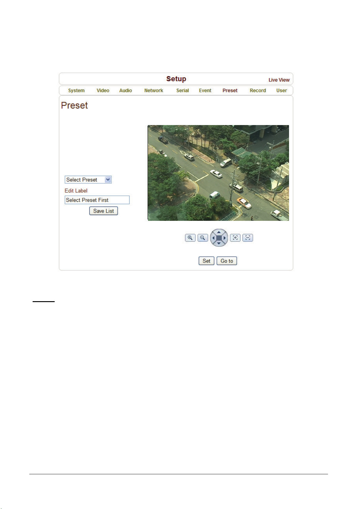
Preset Configuration
Preset
Select preset # and insert the name of preset.
Set camera position for the preset and press Save List button.
Page 49
MCC101 User manual
4. Remote Configuration • 45
Record Configuration
Page 50
46 • 4. Remote Configuration
MCC101 User manual
DISK
SD memory can be used, and at least 1GB size is recommended. Either EXT3 or FAT32 file system can be
used. A disk with either EXT3 or FAT32 file system can be read in Linux PC. However, only disk with FAT32
file system can be read in Windows PC.
Less than 4Mbps of video bit rate is recommended when you record and monitor video simultaneously since
frame dropping may happen due to performance limitation.
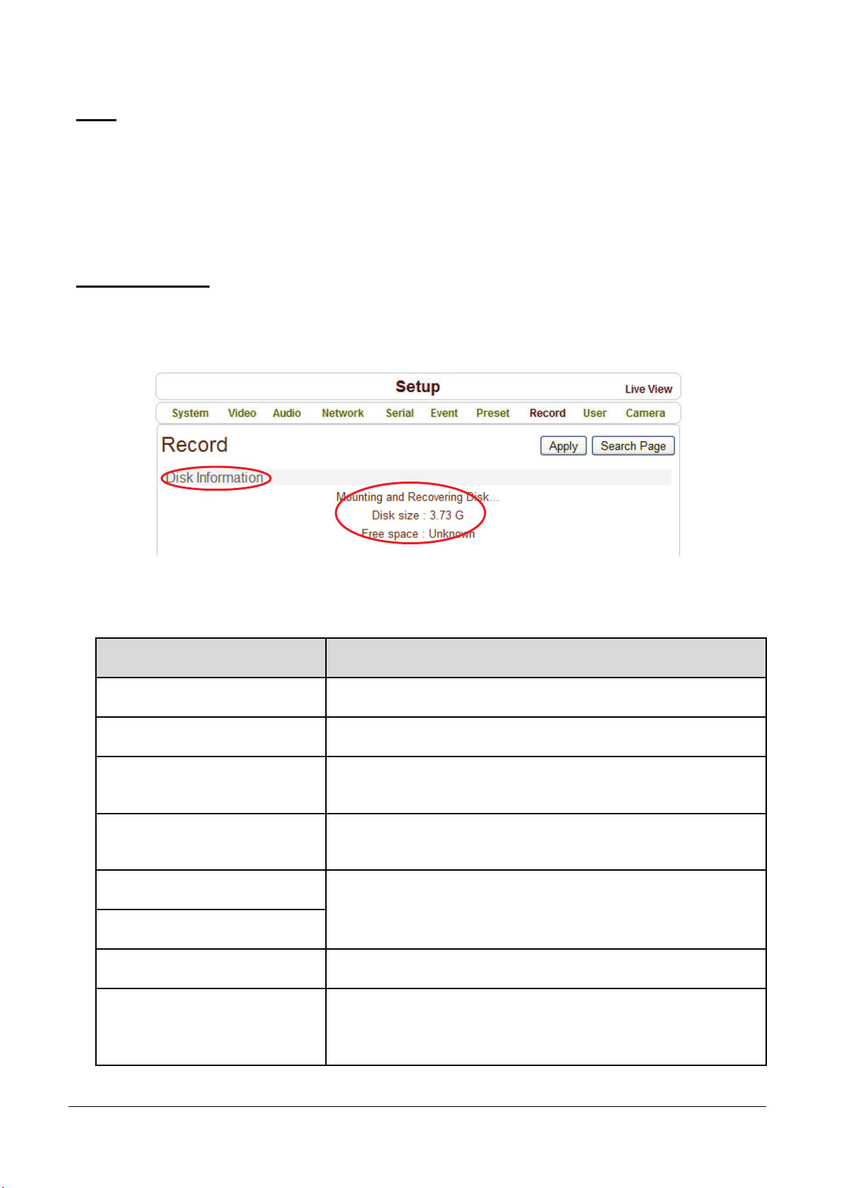
Disk information
Be sure to restart the system after connecting an SD card. During booting, the system reads status of disk
and initializes it. Once the initialization of a disk is finished, the status of disk is shown on Record page of
web-based setup.
Refer to the chart for checking the status of disk.
Disk status Description
Disk error detected Error.
No disk Disk is not connected to the system.
Searching Disk information
Mounting and
Recovering Disk...
Disk format needed
Unknown disk type detected
Checking the status of disk.
Refresh the page and wait until the status is changed.
Performing recovery process when disk damage is found.
It takes from seconds to minutes for recovering.
Disk is attached, but the type of the file
system is unknown or damaged.
USB Disk available Available to be used for recording.
Disk removed or in
abnormal state
Disk is detached during operation or there is damage on the file
system. If it happens while disk is connected, it is recommended
to format the disk.
Page 51

MCC101 User manual
4. Remote Configuration • 47
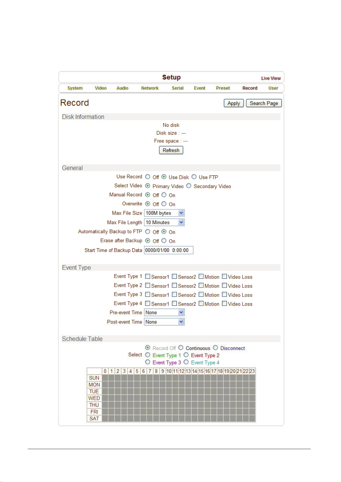
General
Use record
- Off: Recording function will not be used when “Off” is selected
- Use Disk: Recording will be enabled and data will be written to a disk
- Use FTP: Recording will be enabled and data will be uploaded to an FTP server.
In this mode FTP upload by event is automatically disabled.
Select Video
Select video stream to record.
Manual Record
When ON is selected, record is operated regardless of schedule.
Overwrite
When the disk becomes full, the oldest data are deleted automatically.
It is valid only when Use Record is set to Use Disk.
Max File Size/Max File Length
Max File Size option is for limiting the size of AVI file. If small file size is set, files of small size will be
generated but numbers of the files will be increased. Max File Length option is for limiting the time
length of AVI file. If the size of a file becomes Max File Size or the duration of the recording reaches Max
File Length, a new file is created.
Automatically Backup to FTP
Data recorded in the disk can be uploaded to an FTP server automatically for backup.
FTP server is configured on Event page. It is valid only when Use Record is set to Use Disk.
Erase After Backup
Data are deleted in the disk automatically after being uploaded to the FTP server.
It is valid only when Automatically Backup to FTP is used.
Start Time of Backup Data
Specify the time of the data in the disk from which Backup to FTP Disk is performed. This time is changed
automatically as the backup to FTP server goes. So it is useful to check current backup status. It is valid
only when Automatically Backup to FTP is used.
Page 52
48 • 4. Remote Configuration
MCC101 User manual
FTP Base Directory
Specify the name of the directory to be created in the FTP server. It is valid only when Use Record is set
to Use FTP.
Event Type
Three recording modes are supported: Continuous, Event, Disconnect. In case of Event recording, event
types can be selected among several events. Selected event type is used for configuring the schedule table.
Up to 4 event types can be configured and each event type can be a combination of sensor, video loss and
motion event.
Pre-event Time
Specify the duration of recording before an event happens.
Post-event Time
Specify the duration after the event is cleared.
Schedule Table
Actual recording mode is determined by Schedule Table, where recording mode configured by day
(of a week) and hour.
Each of recording mode configures the recording operation as follows:
- Record off: No recording
- Continuous: Records continuously
- Disconnect: Recording is started when the system loses the connection to its last client (Decoder,
VMS/NVR) etc. When there are multiple clients and one of the client is disconnected, this doesn’t happen.
- Event Type: Records when an event configured in Event Type setting happens.
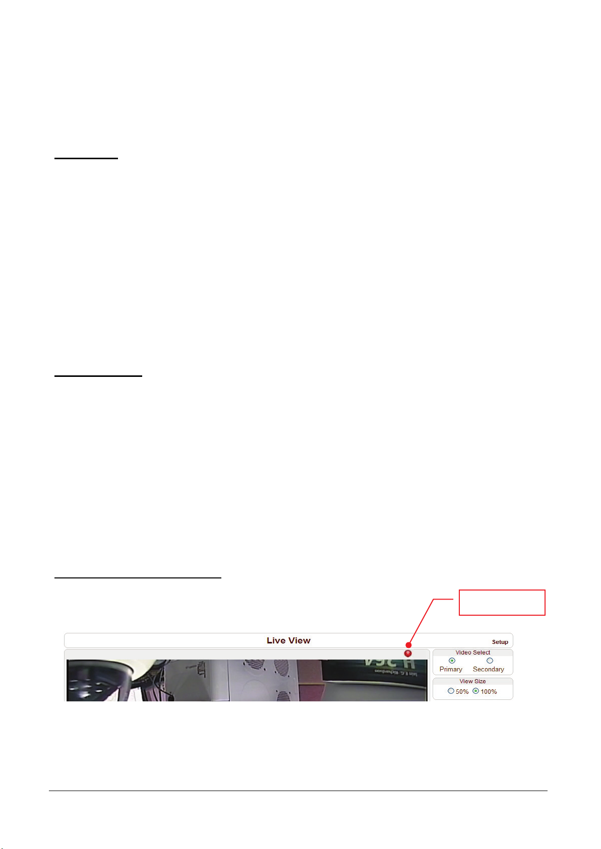
Checking status of recording
Recording status can be checked on the main view page.
Recording status
Page 53
MCC101 User manual
4. Remote Configuration • 49
Search and Playback
Recorded video and audio data can be saved as AVI format in the disk. In general, one AVI file is created for
an event in case of event-based recording. However, it is possible that recorded data by serious of events
happening continuously can be merged to a single AVI file depending on pre/post event time setting. The size
of file is limited to 10 ~ 200MB or 10 minutes. In case of continuous recording, AVI files are created in series
and the size of each is limited to 10 ~ 200MB or 10 minutes.
Search
Actual recording a file currently being recorded doesn’t appear until it is completed.
In case of Continuous recording, a file will be shown after 10 minutes from the start of recording, for a file
is generated every 10 minutes.
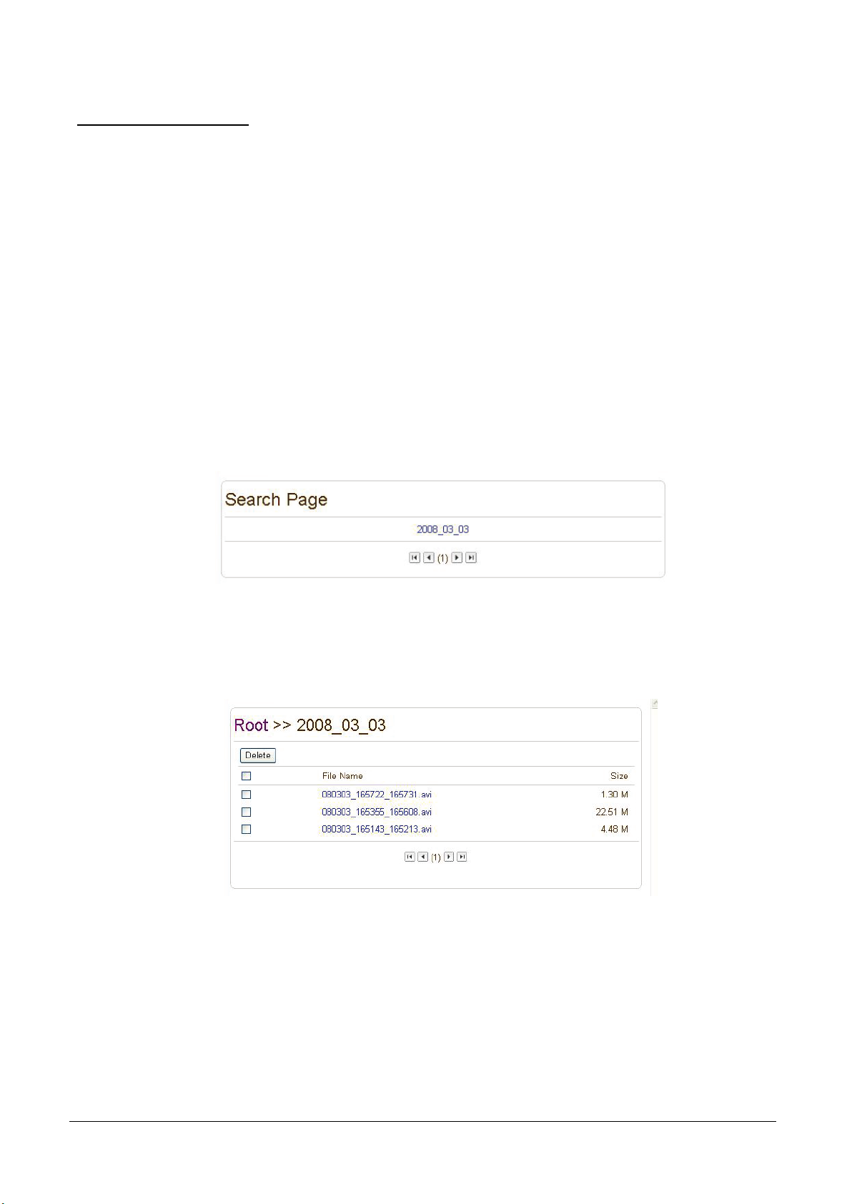
1. Press Search Page button on the Record setup page. Dates with recording data will be shown as follows.
2. First, choose the date for search and the list of AVI files will be shown.
3. The file name shows the date and time: “Date Begin Time End Time.avi”.
4. Press Root to move back to the page with date list.
Page 54
50 • 4. Remote Configuration
MCC101 User manual
Playback
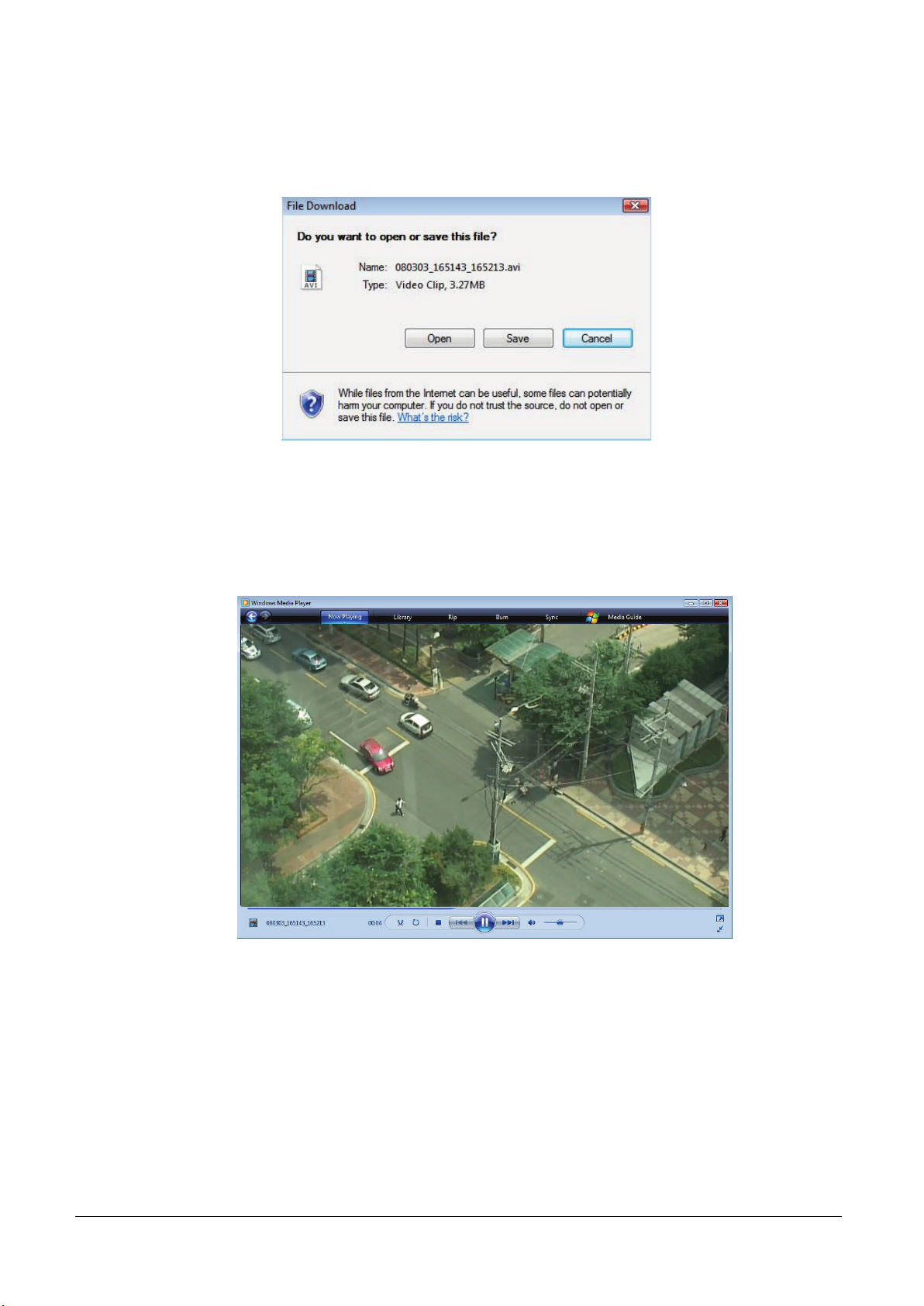
1. Selecting an AVI file will show a dialog for opening or saving the file
.
2. Pressing Save button, the file will be stored in the PC. The AVI file can be played with Windows
Media Player.
3. If you press Open in the dialog, the file will be downloaded and played automatically with Media Player.
4. Another connection through web is disabled during downloading and it is also not allowed to download
two AVI files at the same time.
Page 55
MCC101 User manual
4. Remote Configuration • 51
Deletion of data
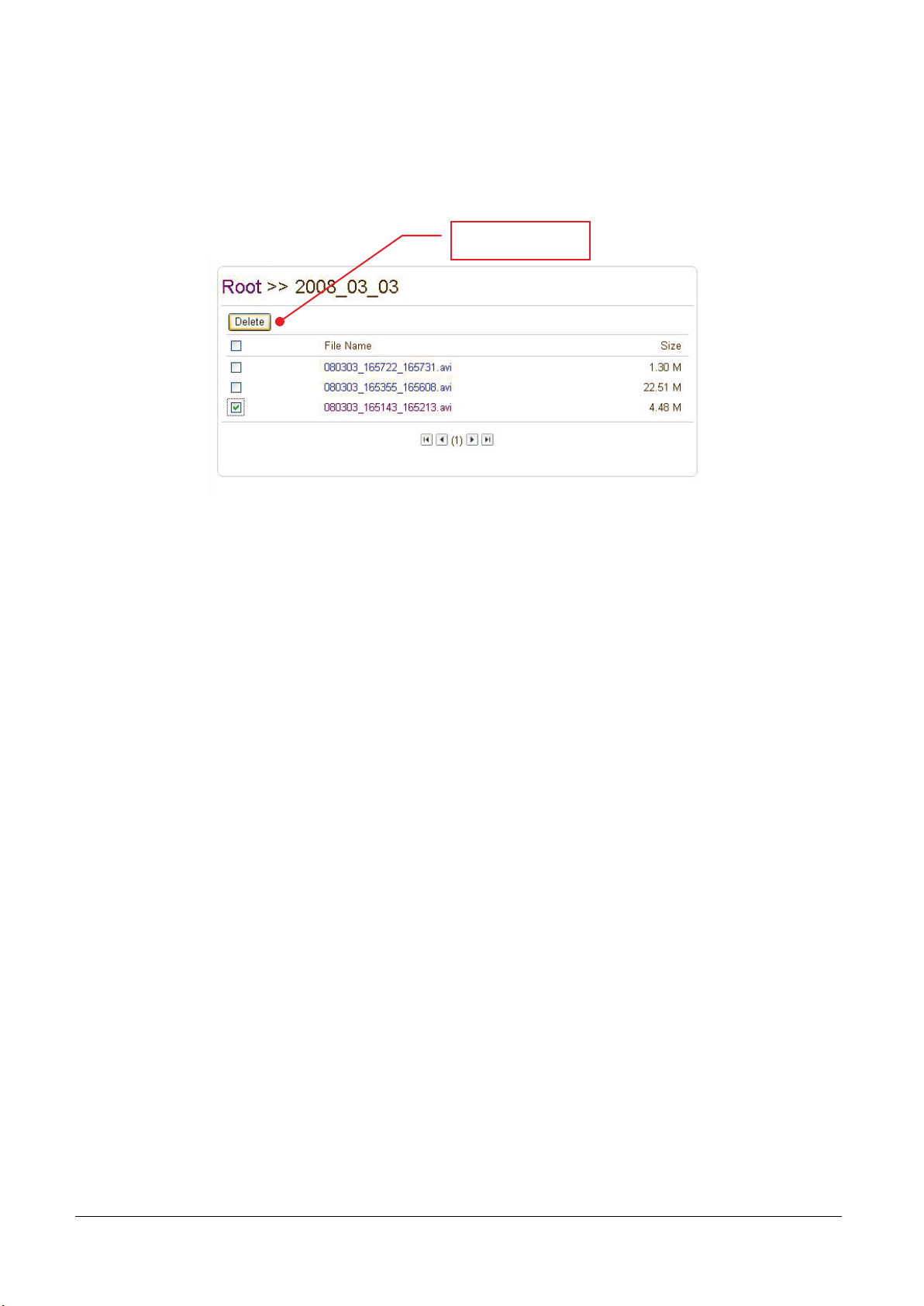
1. If you want to delete recorded files, select the files by checking the item in front of each file and press
Delete button.
2. It is possible to delete multiple files at once.
Press Delete button
Page 56
52 • 4. Remote Configuration
MCC101 User manual
User Configuration
User List
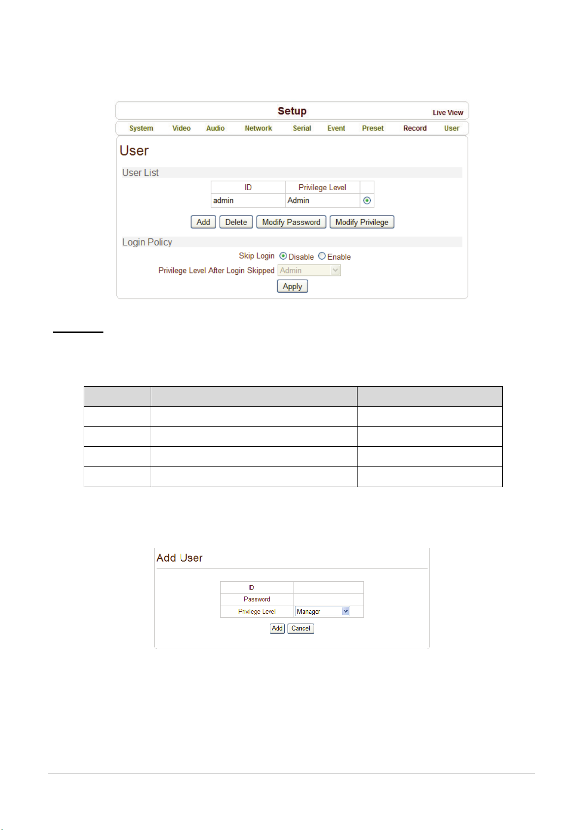
User can be registered and privilege level of a user can be specified. User configuration is allowed only
to admin user. Max 16 users can be registered and each user can have one of four privileges.
Privilege Allowed Operations Remarks
Admin All operations User ID = admin
Manager All operations except for user configuration
User Live viewing and PTZ control
Guest Live viewing only
Add User
Press Add button. The following window will appear.
Enter User ID and password (Up to 15 characters) and select Privilege Level.
Page 57
MCC101 User manual
4. Remote Configuration • 53
Delete User
Select the User to be deleted and press Delete button.
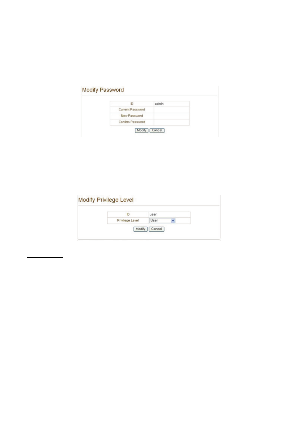
Change Password
Press Modify Password button. The following window will appear.
Enter the current password and then set a new password.
Modify Privilege Level
Press Modify Privilege button to change User level. It is not allowed to change the privilege level of
admin user.
Login Policy
Authentication Type
HTTP authentication based on RFC 2617 (HTTP Authentication: Basic and Digest Access Authentication)
is supported.
Skip Login provides for convenient access to the server when authentication is not required. When Skip
Login is set to Enable, login step is skipped. The privilege level after login in this way is determined by
the setting of Privilege Level after Login Skipped.
Page 58
54 • 5. Decoder Configuration
MCC101 User manual
5. Decoder Configuration
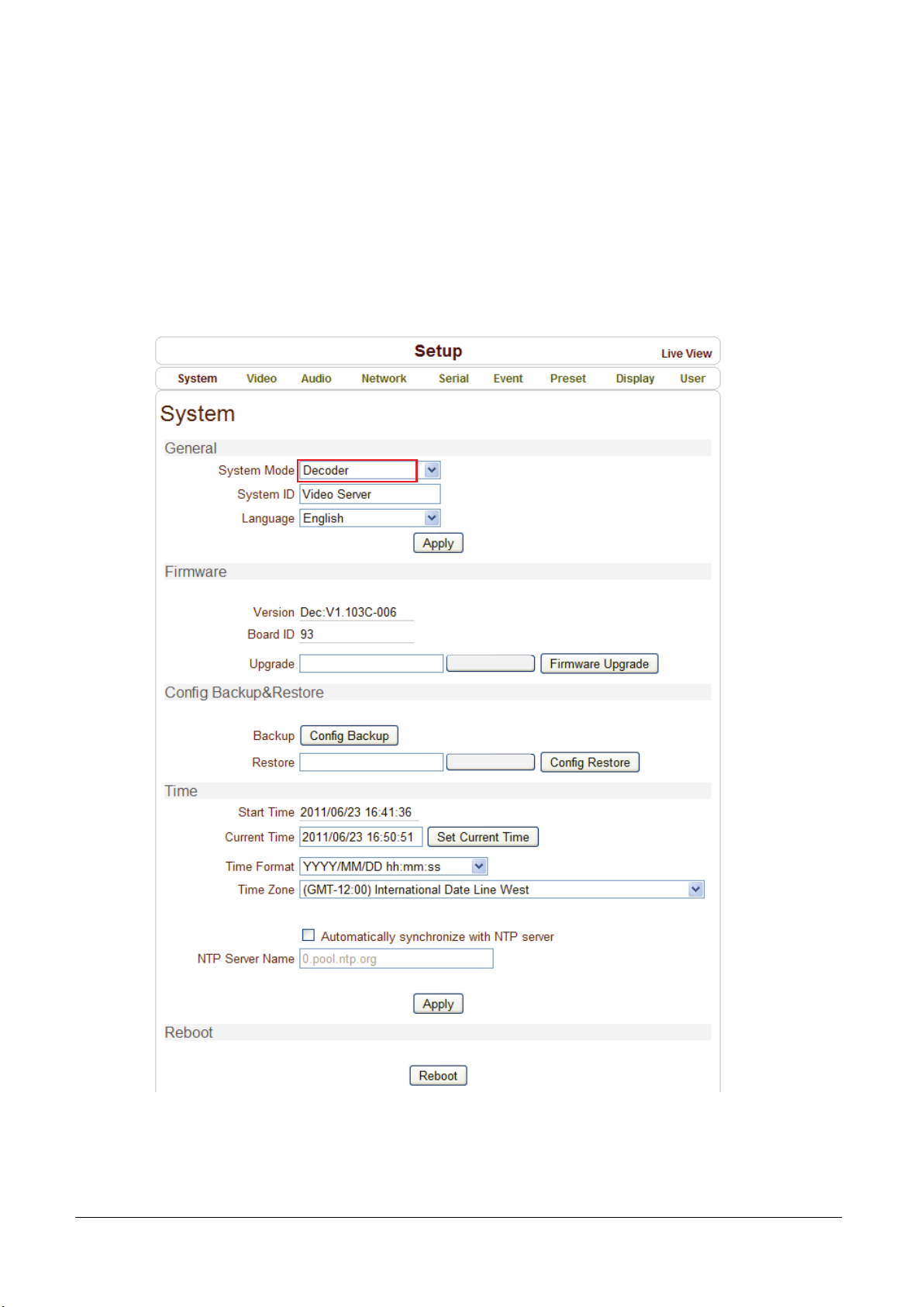
Decoder Configuration is slightly different from Encoder Configuration. Different configurations for the encoder
will be explained in Decoder Configuration.
System Configuration
Page 59
MCC101 User manual
5. Decoder Configuration • 55
Video Configuration
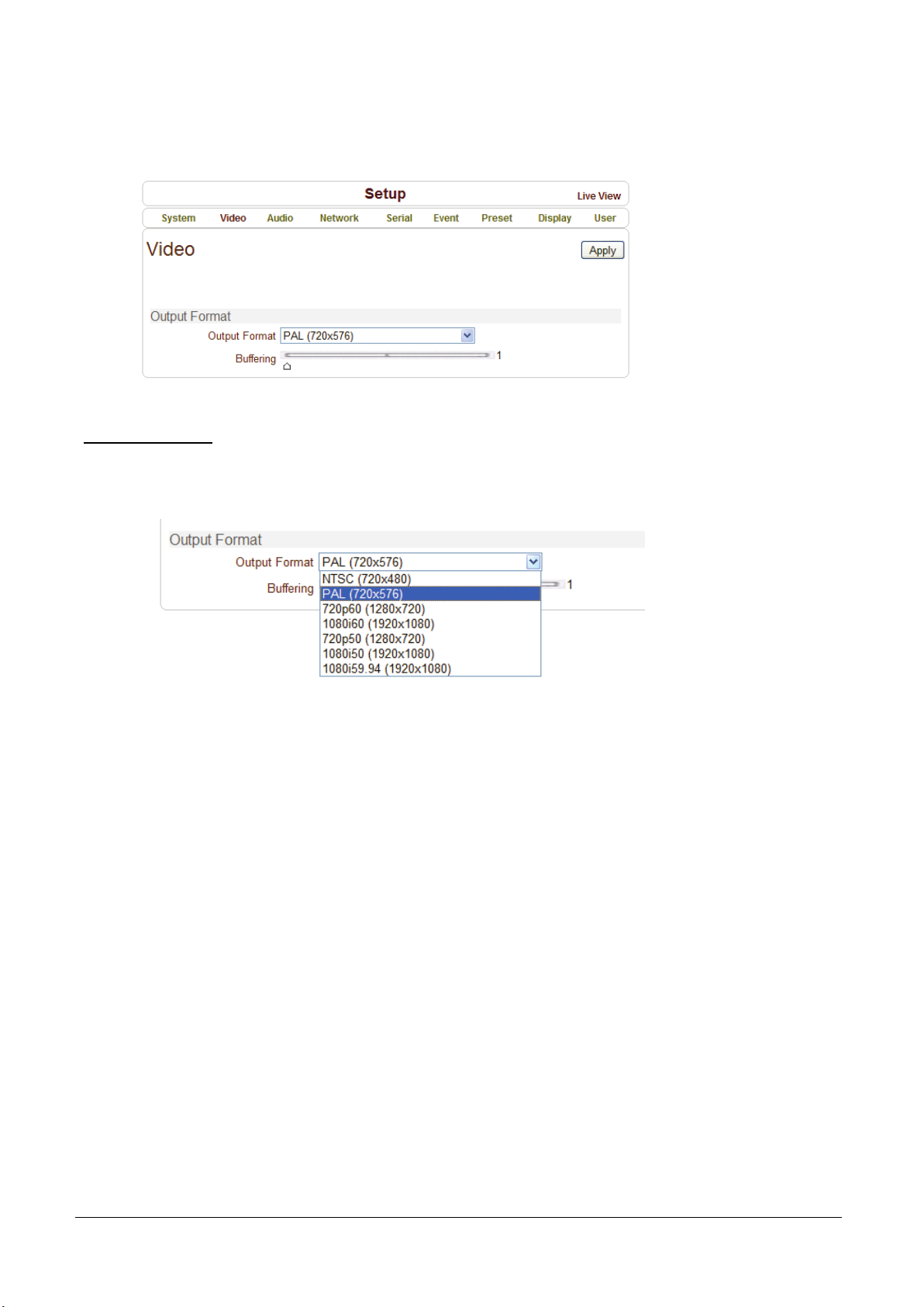
Output Format
Regardless input resolution of Encoder or IP camera, Decoder system of MCC101 can display
video format.
Buffering
You can store maximum 30 decoded frames temporarily by using buffering before displaying the frames.
Displaying stored frames is smoother than displaying in real time. However, displaying stored frames
causes delay because of process of buffering.
Page 60
56 • 5. Decoder Configuration
MCC101 User manual
Network Configuration
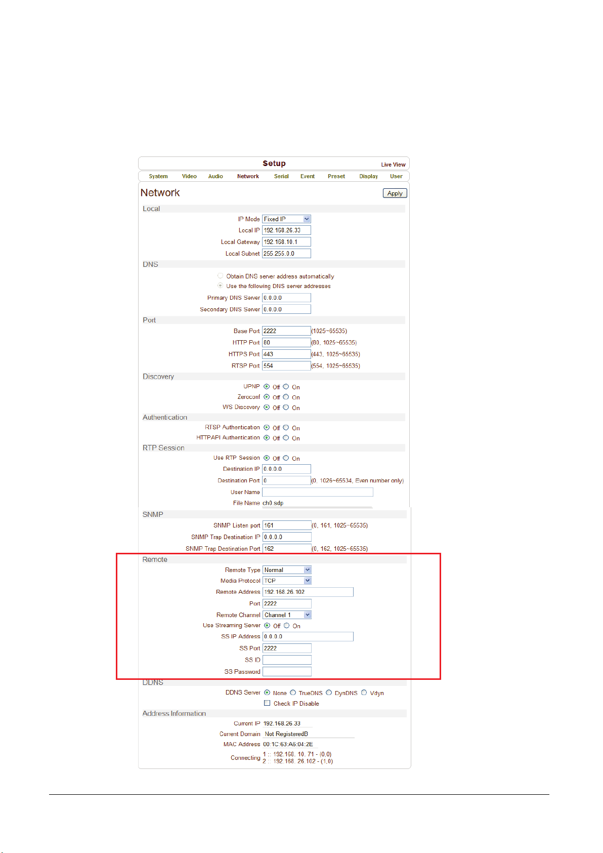
Network page of Decoder has a section for specifying the remote system to connect and the other functions
are same as Network Configuration of Encoder
Page 61
MCC101 User manual
5. Decoder Configuration • 57
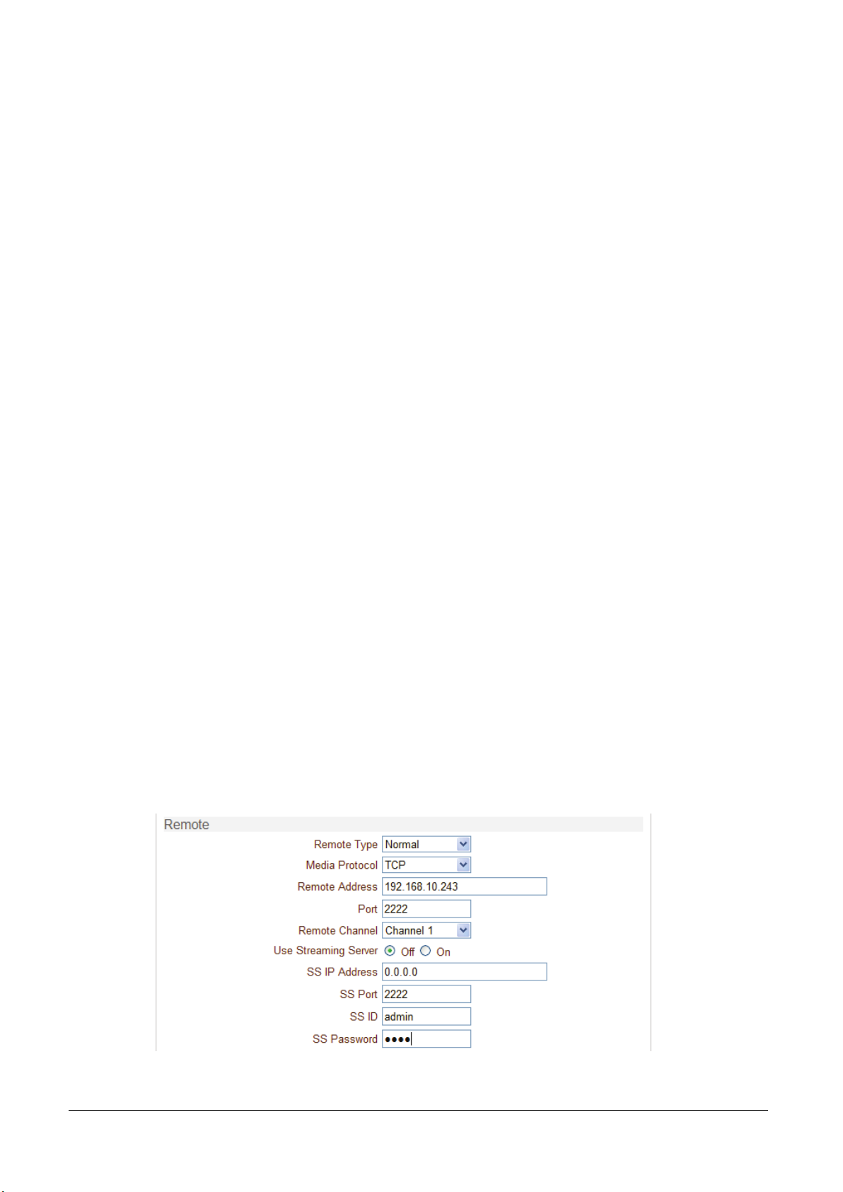
Remote Type
- Normal : Connection for Encoder and decoder.
- RTSP/RTP: Decoder system can make connection though RTSP protocol and get the stream via RTP. It
is also possible to make connection with other vendor’s H.264 IP camera supporting standard RTSP/RTP
and standard H.264 algorithm.
- To make RTSP connection, set Remote Type to “RTSP”, enter the RTSP URL of remote system to
Remote Address, and RTSP access port number to Remote Port. Currently it supports only video.
Media Protocol
Select protocol used for transmission of audio and video data between remote system and decoder.
The decoder system or VMS can choose media protocol among TCP, UDP and Multicast.
Remote Address
Address of the remote system to connect.
Port
Port of the remote system to connect.
Remote Channel
The channel can be selectable when the remote system has more than multiple video channels.
Use Streaming Server
- Decoder system has the settings to connect to Encoder or IP Camera via the Streaming Server. To
connect to Encoder or IP Camera via Streaming Server, Use Streaming Server of Remote group in
Network page should be set to On and information of the Streaming Server (SS) needs to be
configured appropriately.
- SS IP address: IP address of Streaming server.
- SS port: Enter Port number that is set when registering Streaming server.
- SS ID: Enter Streaming Server ID.
- SS password: Enter Streaming Server Password.
Page 62
58 • 5. Decoder Configuration
MCC101 User manual
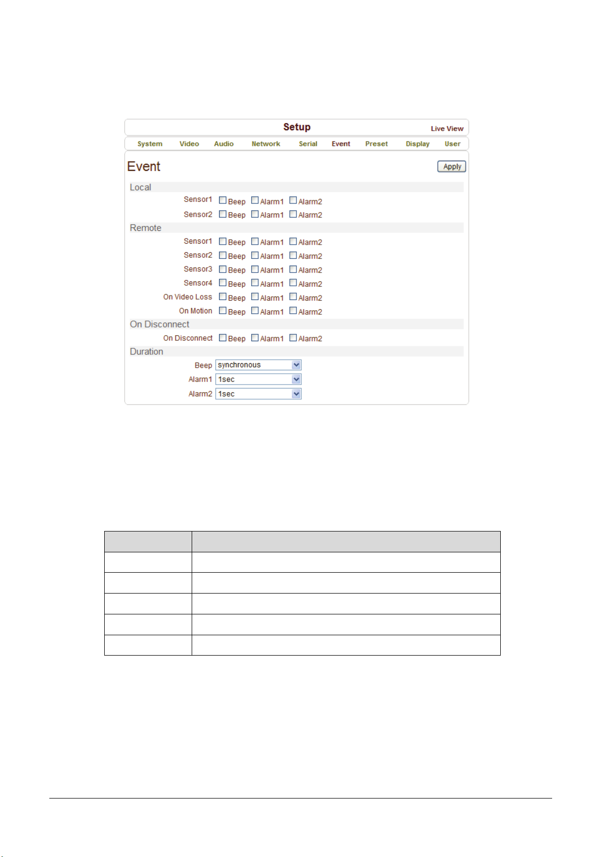
Event Configuration
The event configuration configures the actions for each event type. Local section configures the actions for
events from local (self=Decoder) system, and configuration activates local devices and Remote sections
configures the actions for events from remote (Encoder or IP Camera) system.
The following table lists the possible actions for events:
Action Description
Beep Outputs beep sound using the buzzer in the system
Alarm1/Alarm2 Triggers alarm (relay) port.
E-mail Sends E-mail to the specified address. AVI file can be attached
FTP Upload AVI file to a specified FTP server
Preset Moves the PTZ to associated preset position
Sensor1 / Sensor2
Configure the actions when the sensor 1 or 2 is activated. Multiple actions can be set for a single event.
On Video Loss
Configure the actions when video input signal is lost. Multiple actions can be set for a single event.
Page 63
MCC101 User manual
5. Decoder Configuration • 59
On Motion
Configure the actions when motion is detected. Multiple actions can be set for a single event.
On Disconnect
Configure the actions when the link (connection) with peer system is disconnected. Multiple actions can
be set for a single event.
Alarm and Beep activation duration
Set the duration of alarm or beep activation in case of an event. If it is set to continuous, it will be in active
state until an operator reset it manually.
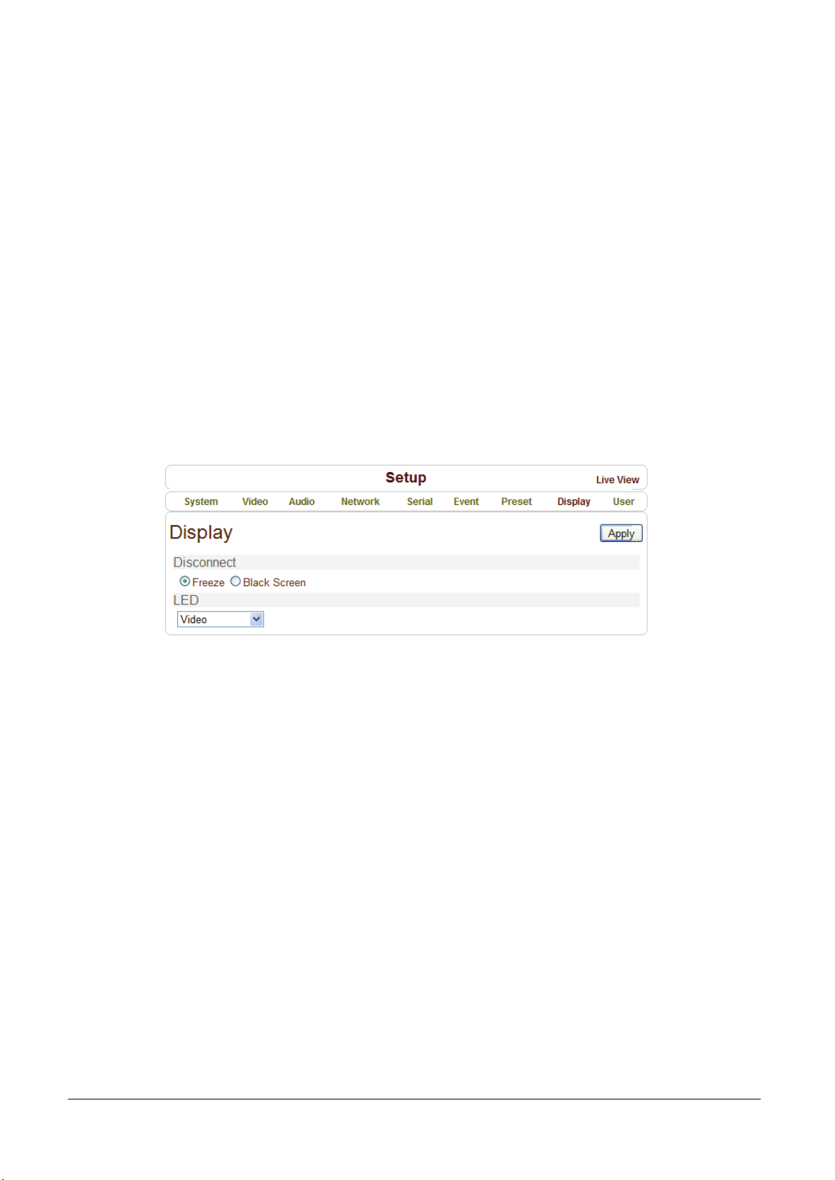
Display Configuration
Disconnection
Decoder system’s output mode on disconnected state can be configured.
- Freeze: Video image of the last frame is shown when there is disconnection.
- Black Screen: Black Screen is shown when there is disconnection.
LED
Select from Video, Audio and Serial to be indicated by Data LED. When there is the selected data
(Video or Audio or Serial) communication between the encoder and the decoder, Data LED will indicate
the status.
Page 64
60 • 6. Appendix
MCC101 User manual
6. Appendix
Appendix A: Sensor and Alarm Port
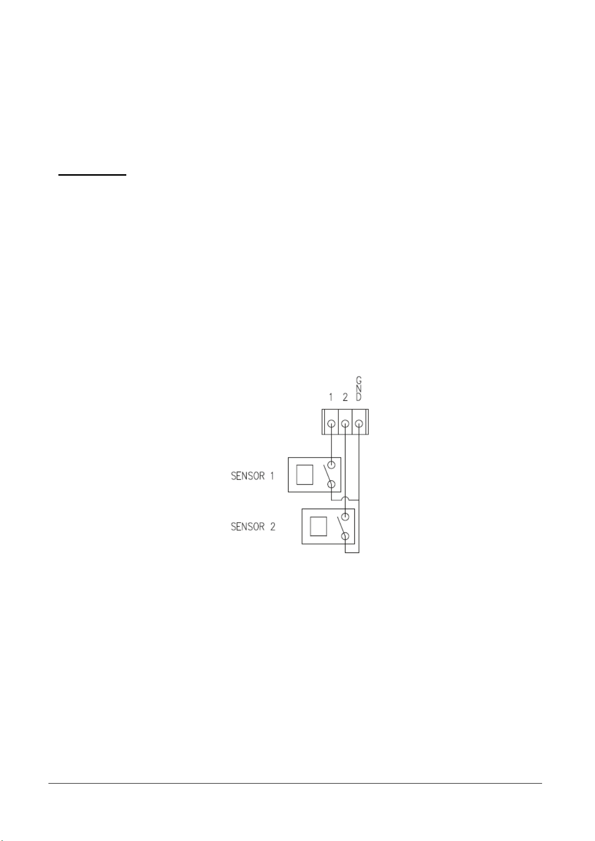
Sensor Port
Terminal Type
- Voltage Rating: 150VAC
- Current Rating: 2A
- Color: Red
Sensor Signal Input Type
- NO Contact Signals
Connection to External Device
Page 65
MCC101 User manual
6. Appendix • 61
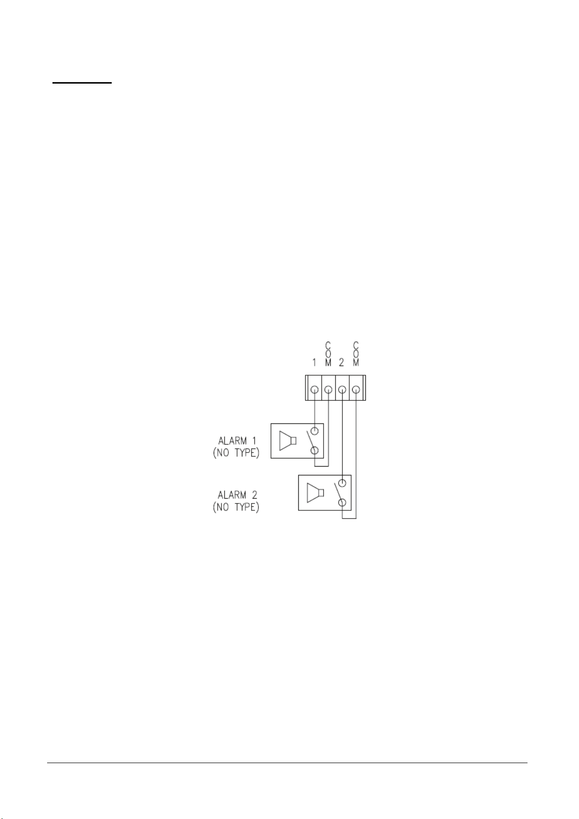
Alarm Port
Terminal Type
- Voltage Rating: 150VAC
- Current Rating: 2A
Relay Type
- Contact Rating: 1A 30VDC
- Switching Power: Max 30W 62.5VA
- Switching Voltage: Max 60VDC
Alarm Signal Output Type
- NO/NC Contact Signals
Connection to External Device
Page 66
62 • 6. Appendix
MCC101 User manual
Appendix B: Serial Port
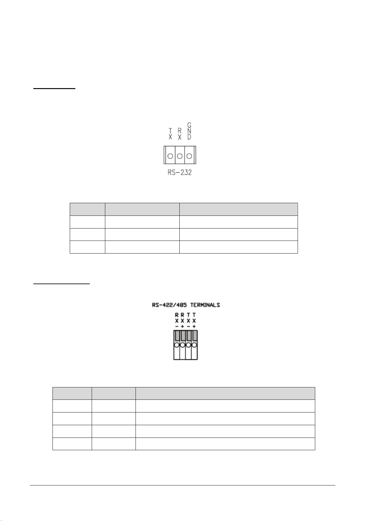
RS-232 Port
Port Type
- 3 PIN
- Pin Arrangement
- Pin Description
Pin NO Pin Name Description
1 TX RS232 TX(Transmit)
2 RX RS232 RX(Receive)
3 GND Ground
RS-422/485 Port
Port Type
- 4 PIN
- Pin Diagram
- Pin Description
Pin No. Pin Name Description
1 RX- RS422 RX-
2 RX+ RS422 RX+
3 TX- RS422 TX- or RS485 TRX- (It is selectable by S/W Setup)
4 TX+ RS422 TX+ or RS485 TRX+ (It is selectable by S/W Setup)
Page 67

MCC101 User manual
Legal Declarations • 63
Legal Declarations
Copyright © 2013 Teleste Corporation. All rights reserved.
TELESTE is a registered trademark of Teleste Corporation. Other product and service marks are property of
their respective owners.
This document is protected by copyright laws. Unauthorized distribution or reproduction of this document is
strictly prohibited.
Teleste reserves the right to make changes to any of the products described in this document without
notice and all specifications are subject to change without notice. Current product specifications are stated
in the latest versions of detailed product specifications.
To the maximum extent permitted by applicable law, under no circumstances shall Teleste be responsible for
any loss of data or income or any special, incidental, consequential or indirect damages howsoever caused.
The contents of this document are provided "as is". Except as required by applicable law, no warranties of
any kind, either express or implied, including, but not limited to, the implied warranties of merchantability and
fitness for a particular purpose, are made in relation to the accuracy, reliability or contents of this document.
Teleste reserves the right to revise this document or withdraw it at any time without notice.
Teleste Corporation
P.O. Box 323
FI-20101 Turku
Street address: Telestenkatu 1, 20660 Littoinen
FINLAND
www.teleste.com
Page 68

64 •
MCC101 User manual
www.teleste.com
 Loading...