

Page 1
OPERATING INSTRUCTIONS
FOR
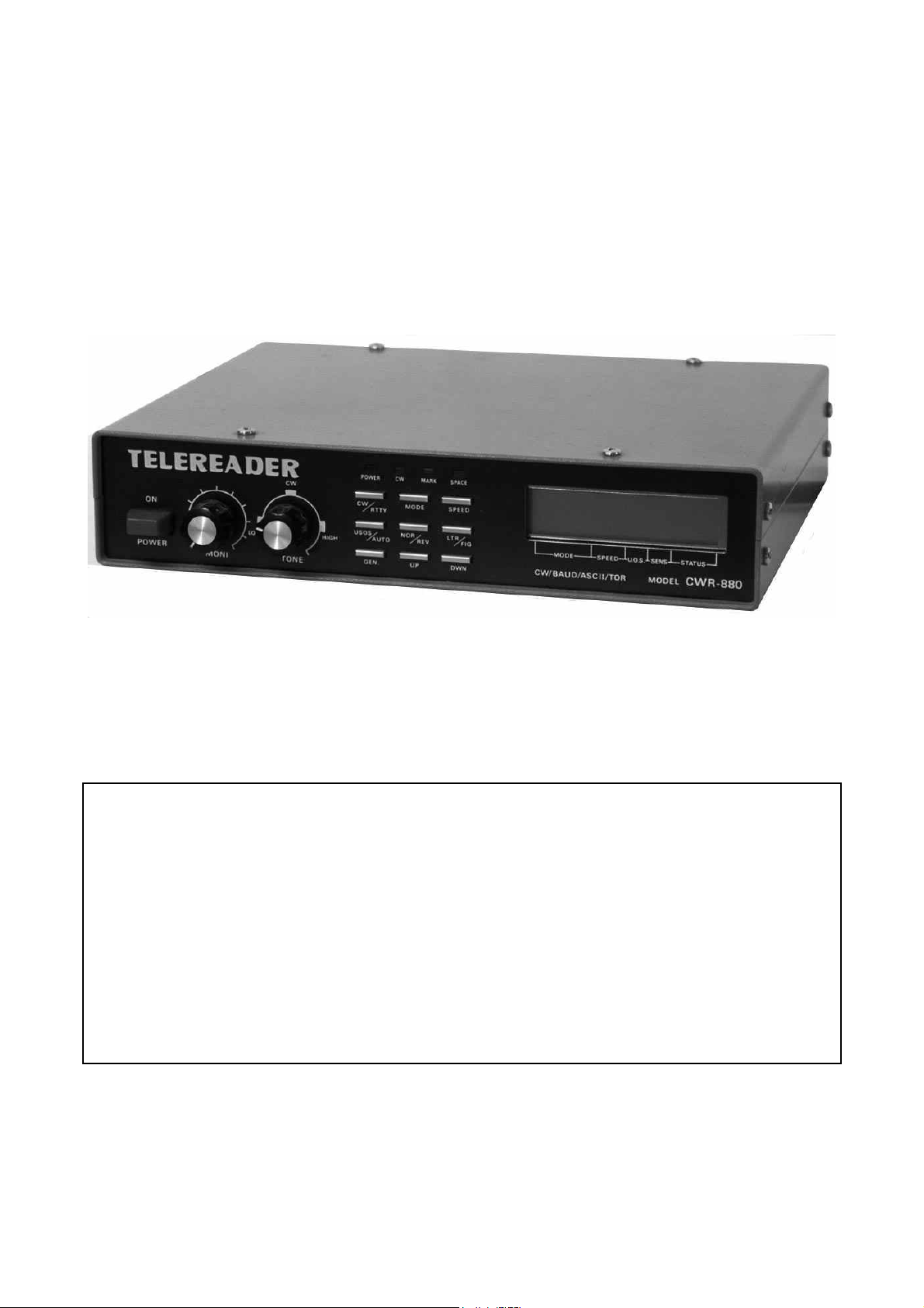
TELEREADER MODEL CWR-880
Page 2

FOREWORD
The TELEREADER CWR-880 you have purchased is a new model of the communication computer
system which incorporates many improvements through the experiences since we released the
first model of the TELEREADER.
Read through this manual t enjoy the TELEREADER's performance to the maximum for a long service life.
CONTENTS
1. Features of CWR-880 ........................................................................ 1
2. Specifications .................................................................................... 1
3. Hook-up ........................................................................................... 3
4. Front panel controls .......................................................................... 5
5. Rear panel connections ..................................................................... 6
6. Decoding when receiving telegraph .................................................... 7
7. Decoding when receiving RTTY .......................................................... 7
8. Telegraph transmission practice .......................................................... 8
9. Random code telegraph reception practice .......................................... 8
10. Test code generating procedure ......................................................... 9
11. TOR ................................................................................................. 9
Page 3

1 – FEATURES OF THE CWR-880
1. CWR-880 is capable to decode any of the data currently used in radio communication and display them on the CRT screen and buil-in LCD display while printing them out at the same time.
2. Either regular color or monochromatic television set, character display CRT or graphic display
CRT can be used as the display monitor. (Display is given in monochrome in every case.)
3. Built-in printer output interface allows connection of a printer to get a hard copy.
4. Built-in CW random signal generator provides for practice in telegraph reception.
5. By directly connecting a key to the CWR-880, you can practice telegraph transmission.
6. In RTTY, the CWR-880 can be used as a test code generator because the test code generating
function is provided in every mode.
7. With the built-in audio monitor circuit, the received or generated signals can be monitored at a
desired volume level.
2 – SPECIFICATIONS
1) Receivable codes
CW: Morse code of alphabet and numeral characters and symbols.
RTTY: 5-unit Baudot code, alphabetic teletype.
TOR: 7-bit international FEC and ARQ error correction system in conformity with
CCIR recommendation 476.
ASCII: 7-unit ASCII code.
2) Signal reception speed
CW: 20 characters/min. - 200 characters/min. (4 – 40 wpm), automatically ad-
justed.
BAUDOT: 45.5, 50, 57, 74.2 baud.
TOR: 100 baud.
ASCII: 75, 110, 300 baud.
3) Input
AF input: 70 mV or over with input impedance of 2.2 kΩ.
Key (TTL) input: Key, contact input or TTL level input.
4) Audio frequency
CW: Center frequency 800 Hz (750 – 850 Hz, continuously changeable).
RTTY: 1275 Hz – 2125 Hz, continuously changeable.
1
Page 4

5) Output
VIDEO OUT: 1 VPP composite video signal, NTSC system.
RF OUT: UHF (591.25 MHz) NTSC system.
Printer: Centronics compatible parallel data transmission.
KEY OUT: Key output for transmission and test code output (Transistor switching for
+ keying).
6) Number of characters displayed
CRT: 40 characters × 24 lines (2-page buffer) with the operation status indication
in the bottom line.
LCD: 16 characters × 2 lines (60 -page buffer).
7) Morse code, random code generator
Alphanumeric characters
Speed: 4 wpm – 30 wpm (20 characters/min. to 150 characters /min.)
8) Text code generator
BAUDOT: Continuous output of QBF.
ASCII: Continuous output of QBF.
TOR: Continuous output of QBF.
Speed of test code generation
BAUDOT: 45.5, 50, 57, 74.2 baud.
ASCII: 75, 110, 300 baud.
TOR: 100 baud.
9) Power requirement
DC 12 V – 14 V, 720 mA
10) Overall dimensions
W 220 mm × D 170 mm × H 50 mm
11) Weight
approx. 1.5 kg
12) Accessories
Instruction manual 1 copy
Video cable 1 pc.
Audio cable 1 pc.
Earphone plug 2 pcs.
Fuse (1 A glass tube) 1 pc.
2
Page 5
3 – HOOK-UP
1) Hooking up the power supply
After making sure that the stabilized power source provides voltage within the range from 12 V
to 14 V, turn off the the power switches of the power source and the CWR-880. Then connect
the red wire of the CWR-880's power cable to the positive terminal and the black wire to the
negative terminal of the power source.
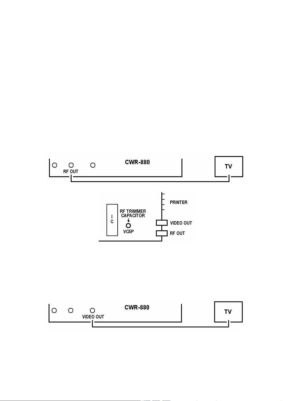
2) Hooking up a television set
Connect the RF OUT terminal of the CWR-880 and the UHF antenna terminal of the television
set with the attached video cable, after cutting off the RCA plug at one end of the cable. The
RF output uses the 591.25 MHz channel of the television. If you receive a television broadcast
in this channel, change the output frequency of the CWR-880 by adjusting the trimmer capacitor (VX5P) within the range from 573.25 MHz to 603.25 MHz.
While both monochromatic and color television sets can be used, display is given in monochrome in both cases.
3) Hooking up a display monitor
Connect the VIDEO OUT terminal of the CWR-880 and the VIDEO IN terminal of the display
monitor with the attached video cable. While a color display monitor can be used, display is
shown in monochrome. Display monitors of horizontal synchronization frequency other than
15.75 kHz cannot be used.
3
Page 6
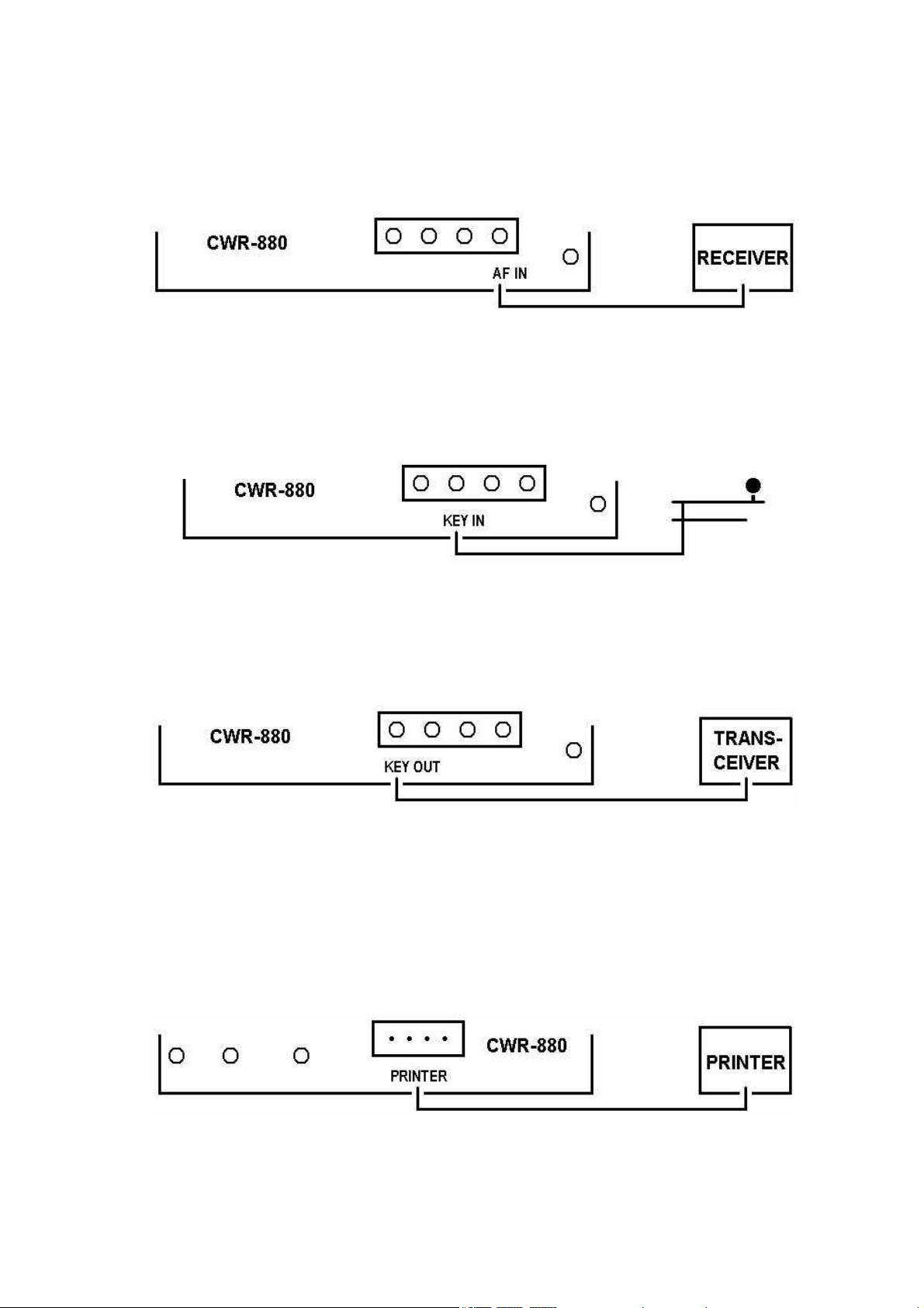
4) Hooking up a receiver
The CWR-880 decodes audio signal fed from a receiver. Connect the AF IN terminal of the
CWR-880 and the headphone output terminal of the receiver with the attached audio cable.
5) Hooking up key
Connect the KEY IN terminal of the CWR-880 and the contact terminal of the key with the attached earphone plug. Prepare a shielded wire or a 2-core cable for the connection by yourself.
6) Connection for KEY OUT signal
Connect the KEY OUT terminal of the CWR-880 and the KEY terminal of the transceiver with
the attached earphone plug. Prepare a shielded wire or a 2-core cable for the connection.
7) Hooking up a printer
Centronics- compatible printer of parallel interface can be used with the CWR-880. This means
that the CWR-880 can use almost all printers which are used with personal computers. A printer is to be connected with the printer cable available as an optional accessory.
Since LF is the only code for line feed on the CWR-880, set up the printer to enable printing
with line feed.
4
Page 7
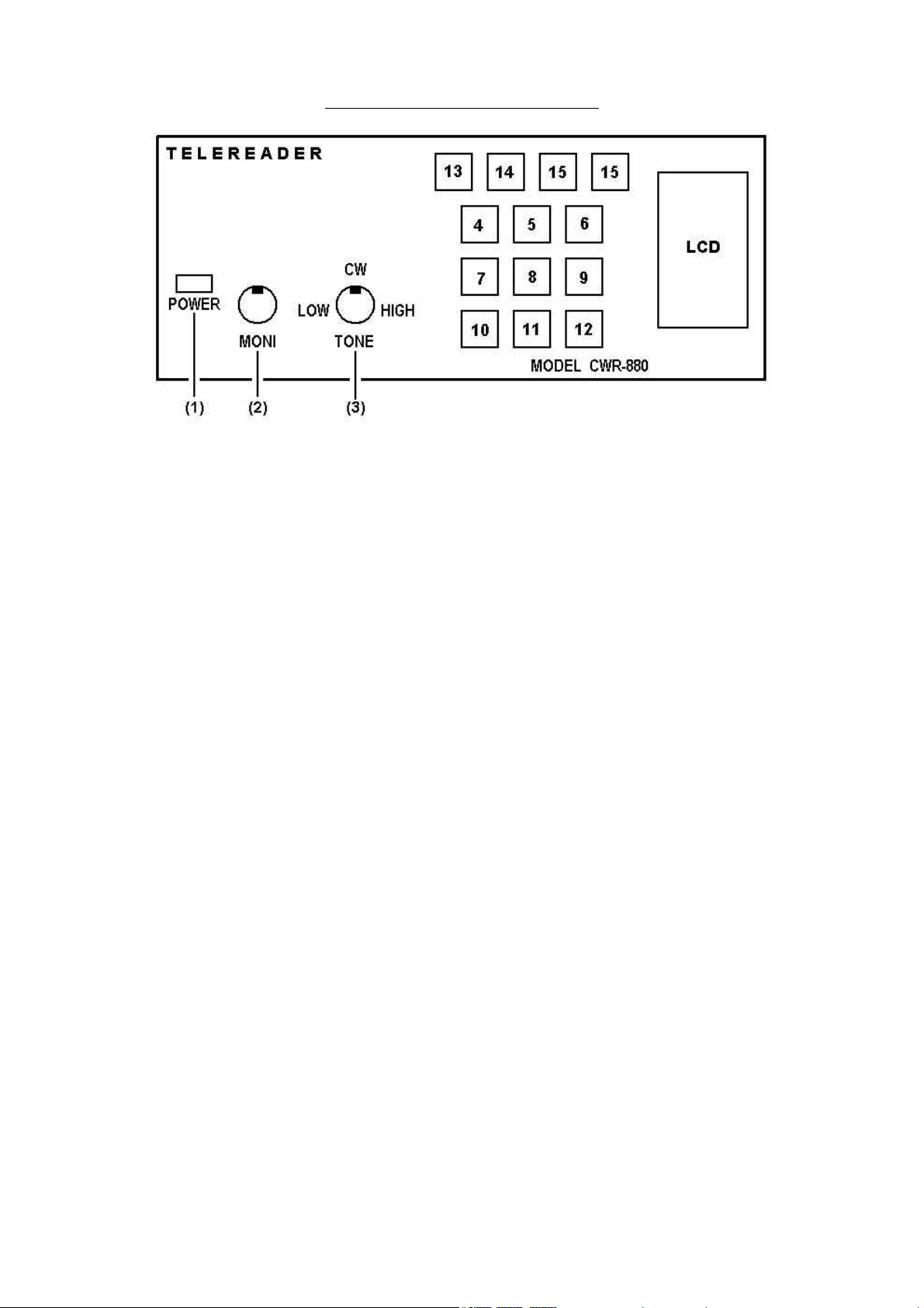
4 – FRONT PANEL CONTROLS
1) POWER: Power switch
2) MONI: Volume adjustment of audio monitor
3) TONE: Frequency adjustment of input audio signal
CW: 750 Hz – 850 Hz, continuously changeable
RTTY: 1275 Hz – 2125 Hz, continuously changeable
4) CW/RTTY: CW (telegraph) / RTTY (radio teletype) selector pushbutton switch
5) MODE: Operation mode selector pushbutton
In CW operation: Alphabetical letters
In RTTY operation: Baudot ➠TOR ➠ ASCII
6) SPEED: Baudot 45 ➠ 50 ➠ 57 ➠ 75
TOR Synchronized reset
ASCII 110 ➠ 300 ➠ 75
7) USOS
In RTTY operation: Unshift-on-space function pushbutton
AUTO
8) NOR
Input polarity selector pushbutton in RTTY operation: Normal ➠ Reverse
REV
9) LTR
Letter case changeover pushbutton in RTTY operation: LTR ➠ FIG
FIG
10) GEN: CW operation: Starts random code generation. ON ➠ OFF
11) UP: Scroll up the screen
12) DWN: Scroll down the screen
(UP and DWN switches effects continuous scrolling when kept being pressed.)
5
Page 8
13) POWER Power indicator LED
14) CW Telegraph synchronization indicator LED
15) MARK
RTTY synchronization indicator LED
SPACE
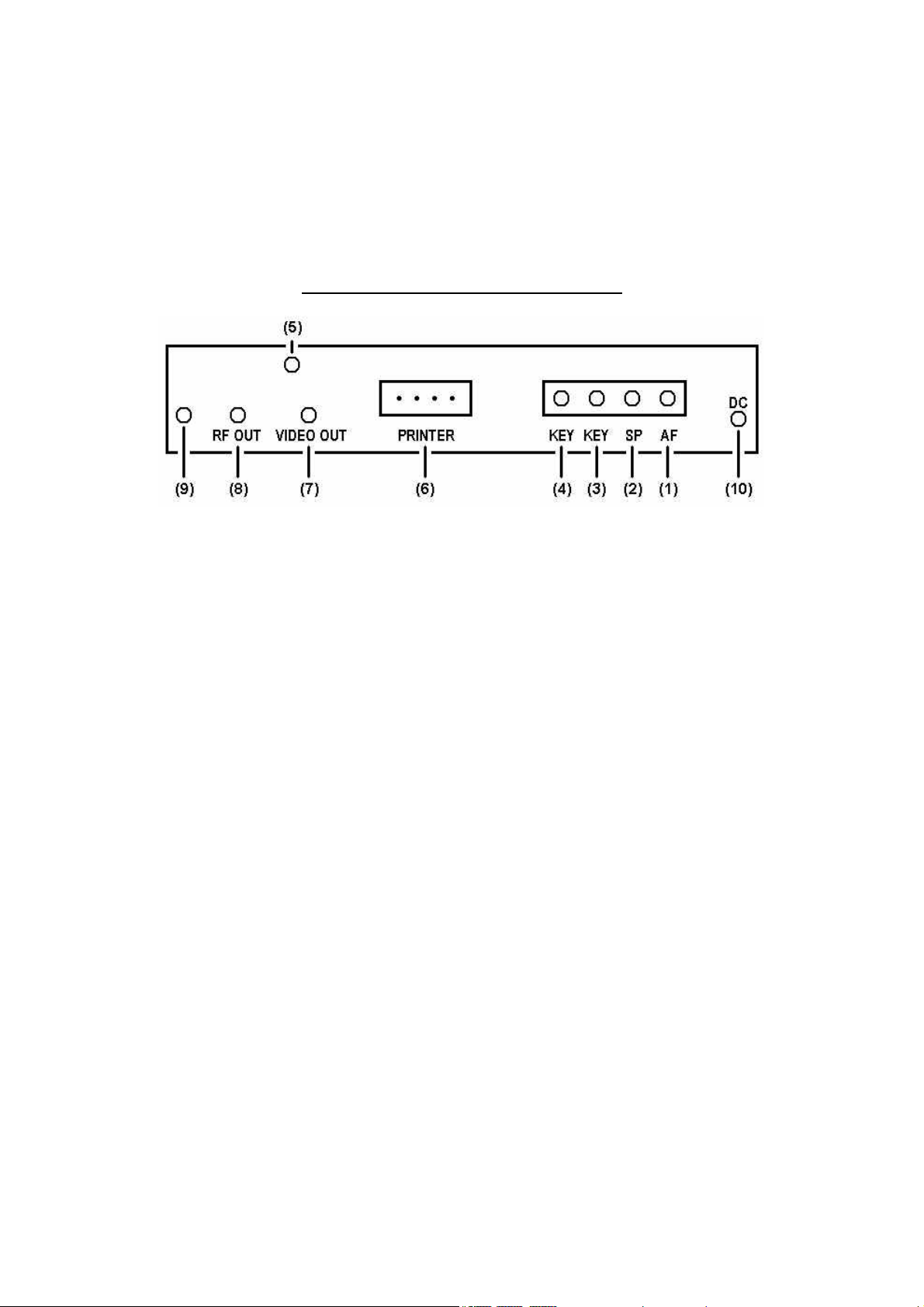
5 – CONNECTION ON REAR PANEL
1) AF IN: Input terminal for audio signal.
2) EXT SP: Output terminal for external speaker (Connected to AF IN internally.).
3) KEY IN: CW operation: Input terminal for key.
RTTY operation: Input terminal for external demodulator signal in TTL level.
4) KEY OUT: CW operation: Output terminal for the key signal to a transceiver. Random code
generated is also provided on this terminal.
RTTY operation: Output terminal for test code.
5) LCD: Contrast adjust knob for LCD.
6) PRINTER: Output terminal for printer.
7) VIDEO OUT:
Output terminal for display monitor.
8) RF OUT: Output terminal for a domestic television set.
9) GROUND: Grounding terminal.
10) Red & black cable:
Power cable to connect an external stabilized power source of 12 VDC to 14 VDC,
1 A or over.
6
Page 9

6 – DECODING WHEN RECEIVING TELEGRAPH
1) Set the desired reception sound volume with the AF control of the receiver.
2) If your receiver set is equipped with a CW filter, make the CW filter effective.
3) If your receiver is equipped with IF shift control, pass band tuner or notch filter, set the peak
reception volume at the frequency of 800 Hz.
4) Set the TONE control knob of the CWR-880 at the center position and tune the receiver to re-
ceive 800 Hz signal. CW LED will flicker in synchronization with the reception sound and decoded characters will be shown on the display monitor. If the CW LED does not flicker in synchronization with the reception sound, decoding is not done normally; tune the receiver again or
make fine adjustment with the TONE knob.
7 – DECODING WHEN RECEIVING RTTY
Teletype for amateur radio station
1) When the CW/RTTY selector of the CWR-880 is set to RTTY, a message "BAUDOT SPEED 45b
NOR" appears on the display, which shows that the reception with an amateur radio station is
enabled. Place the TONE VR knob at the position "HIGH" and set the receiver in LSB or FSK
mode. Turn the receiver tuning dial gradually from the position of lower beat to that of higher
beat. First the MARK LED flickers. Tuning the dial further to higher position (shifting by 170
Hz), the MARK LED and SPACE LED will flicker with correct decoding started. Flickering of only
the SPACE LED indicates improper tuning. In such a case tune the receiver again or adjust the
TONE VR finely to make the MARK LED also flicker.
2) When the received characters are changed to numerical figures or symbols due to noise or oth-
er interference during reception of ordinary alphabetical characters, set the USOS switch in ON
position and normal alphabet will be obtained when space signal is received.
3) LTR/FIG switch is to changeover between alphabet and numeral every time it is pressed. When
alphabet is changed to numeral due to noise or other interference, press this switch to obtain
the normal decoding.
4) Set the NOR/REV switch to REV to receive signals of reverse shift. Reverse shift is obtained al-
so when receiving from KEY IN (TTL IN).
Teletype in commercial station
While setting procedures for teletype in commercial station are almost the same as those of
amateur station, the receiver mode is to be set to USB. As the transmission speed of 50 baud
is widely used, set the SPEED to 50b. Since some stations transmit at 57 or 75 baud, try these
speeds if normal decoding is not obtained. Signals from many unidentified stations cannot be
decoded at all. Because signals from commercial stations have wide shift width, tuning is easier
than amateur station.
Teletype of TOR system
TOR system teletype is equipped with automatic error correction function which corrects a misreceived character automatically. Intermittent reception sound like "chee chee chee" is given in
7
Page 10

ARQ operation and rapid continuous reception sound at 100b is given in FEC operation. The reception speed is fixed to 100b by pressing the MODE switch to select TOR.
The following status indications are shown on the display:
WAIT: Standby for signal reception where all signals and noises are ignored until TOR sig-
nal is received.
IDLE: When a TOR signal is received and tuned with the CWR-880, IDLE is displayed in-
stead of WAIT.
TRAF: When a message is received in IDLE status, the indication changes from IDLE to
TRAF and decoding is started.
ARQ and FEC are discriminated in the CWR-880 automatically and ARQ or FEC is indicated.
AMTOR used by amateur radio stations are conformity with international coding system and
synchronization resetting can be done with the SPEED button.
O In ASCII and JIS codes, which are rarely used in short wave and, 110 baud is usually adopted.
The demodulator incorporated in the CWR-880 can match at a speed of up to 110 baud. For
signal reception at a speed over 110 baud, use a high speed modem with its output signal fed
to the KEY IN (TTL IN) terminal.
8 – PROCEDURE FOR PRACTICE OF TELEGRAPH
TRANSMISSION AND RECEPTION
1) Turn on the power switch and a message "MORSE ENG" will appear.
2) Connect a key to the KEY IN (TTL IN) terminal of the CWR-880 and strike Morse code. The de-
coded characters will be shown on the display.
3) Strike the key correctly so that correct characters are displayed, for a signal not defined in the
Morse code system cannot be decoded.
9 – PRACTICE OF TELEGRAPH RANDOM CODE RECEPTION
1) Select "MORSE ENG" mode and press GENE button. Transmission sound will be given followed
by the display of character corresponding to the generated code. Five characters are sent as
one block.
2) Every time the SPEED switch is pressed, the speed is increased by 1 wpm from 4 wpm to 30
wpm. 4 wpm comes next to 30 wpm.
3) With a printer connected, the displayed characters can be continuously printed out.
4) Press the GEN button again to stop the random code generation.
NOTE: Speed can be converted from wpm to characters/min. by multiplying wpm by 5.
8
Page 11

10 – TEST CODE GENERATING PROCEDURE
1) Set the CW/RTTY selector to RTTY.
2) Set the MODE button to the desired mode.
3) Press the GEN button. The audio monitor will give a transmission sound and, at the same time,
a test code will be provided at the KEY OUT terminal.
4) The speed can be changed by pressing the SPEED button.
5) In TOR mode, ARQ or FEC is selected by pressing the USOS/AUTO switch.
6) Press the GEN button again to stop the test code generation.
11 – TOR
The CWR-880 is equipped with TOR mode decoder function which is not widely known. Here the
outline of the TOR mode and the operating procedure will be explained.
TOR is a communication system in conformity with the CCIR recommendation 476-2 which was
adopted in the second general meeting of CCIR in 1970 for the purpose of improving the maritime
communication, comprising two fundamental communication modes, ARQ (Automatic Request for
Repetition) and FEC (Forward Error Correction).
ARQ (Automatic Request for Repetition)
ARQ is used mainly in individual communication between a coast station an a ship station. In ARQ
mode, if an error is detected in the received characters, request for retransmission is sent automatically until the correct character is received, ensuring virtually error-free transmission. In this
mode, however, only one receiving station is allowed, rendering the communication privacy. (But
the CWR-880 is capable of decoding the communication between two stations by means of a special method.)
FEC (Forward Error Correction)
FEC is a one-way error correction system of time diversity feature which transmits the same character twice. An erroneous character which cannot be corrected is shown by a space. This system is
suited to the transmission of a same message to a number of stations, such as broadcast transmission.
Amateur radio station
(Since AMTOR for amateur stations conforms to international standard, an amateur station can receive with international TOR system.)
3.5 MHz band: Around 3.574 MHz, around 3.630 MHz
7 MHz band: 7.075 MHz – 7.095 MHz
10 MHz band: Around 10.145 MHz
14 MHz band: 14.070 MHz – 14.080 MHz
21 MHz band: Around 21.075 MHz
28 MHz band: Around 28.705 MHz
9
 Loading...