


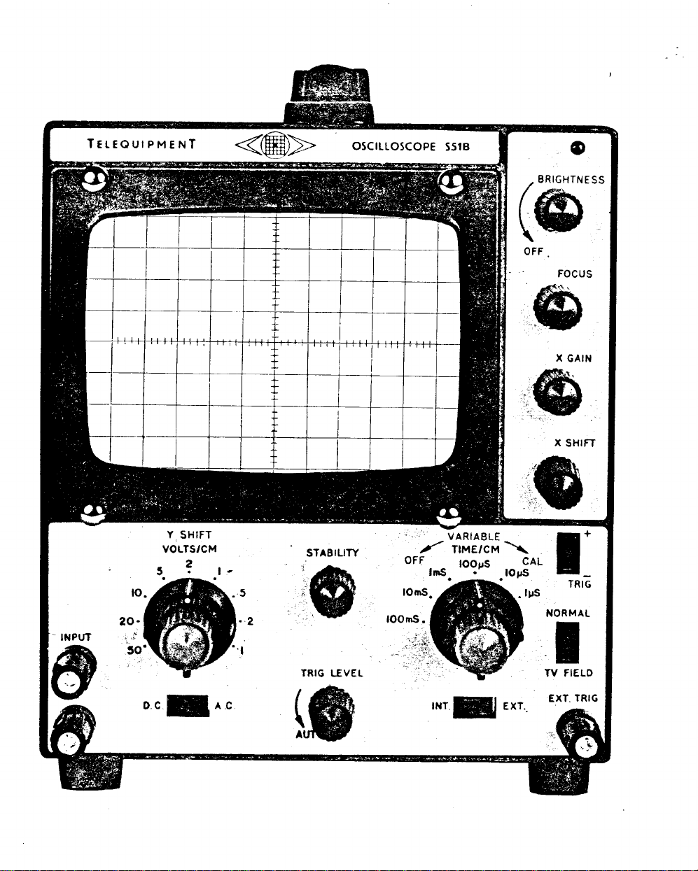
S51E

TELEQUIPMENT
OSCILLOSCOPE
TYPE
AND
S51E
S51B
All TelequipmenT instruments are the subject of
continuous development and improvement, and,
in consequence,may incorporate minor detail
changes from the information contained herein.
TelequipmenT is a registered trade mark of
TELEQUIPMENT LIMITED*
313 Chase Road
Southgate
London, N. 14.
England.
Telephone: 01-882 1166
Cables: TELEQUIPT LONDON N 14

VERTICAL AMPLIFIER
CIRCUIT DESCRIPTION
The vertical amplifier consists of three double triodes.
cathode coupled amplifier stage with RV6 acting as the gain control.
The signal is taken from Vlb anode and drives the output stage V3 via
cathode follower
V3 consists of a long-tailed pair with the signal taken to
shift applied to
V2b
acts as a low impedance HT supply for
15OV
resistor
TRIGGER CIRCUIT
for Y shift and timebase circuits.
The signal at the anode of
The HT supply for the trigger circuit, V4 and
R15
in the cathode circuit of V3.
V2a.
V3b.
V1,
also providing approximately
V3b
is taken to the INT-EXT trigger switch.
V5b
is taken from a common
Vla and b form a
V3a
and the vertical
The trigger selection is performed by three switches in the
S51E; S2
splitter
connects it to S4 which either passes the signal directly or via an integrating circuit
to V4a.
waveform and attenuates the line pulses allowing the time base to be triggered by
the field sync pulses.
bistable switch, the switching level being adjusted by the grid potential of
On the AUTO position the switch S5 is opened and the grid of
the grid of
determined by the time constant R42 and C19, but as soon as any input signal
between about
ceases and the multivibrator
appearing at the anode of
and the negative pulse used to trigger the time base.
selects the INT-EXT triggering signal and connects it to the grid of phase
V4b.
The latter position,
From
S3 selects the positive or negative output of the phase splitter and
TV FIELD, integrates the field pulses of a television
S4
the signal is fed to
V5b.
In the absence of a signal
50Hz
and
1MHz
V5b
V4a
and
is applied to the grid of
synchronises
is differentiated,
V5b
which form a cathode coupled
V4a
and
to the signal frequency.
the positive pulse removed by MR7
V5b
oscillate at a frequency
V4a,
S51B
and one in the
V4a.
V4a
is returned to
the self-oscillation
The square wave

TIMEBASE &
V6a
S8
and the VARIABLE speed control.
HORIZONTAL AMPLIFIER
is the Mi l ler sweep generator,
the speed of run down being controlled by
The Miller valve is keyed by
V5a
and
V6b
multivibrator.
In the rest position of the timebase,
clamped by MR8 and 9.
lowers the grid potential of
coupled to the grid of
V6b
is conducting.
V6b
and hence that of the anode of
V6a,
so reducing the valve current.
screen potential developed across
V5a.
This causes
whereby
V6b
becomes quickly cut off and
V5a
anode voltage to
R65
V5a
is coupled via R54 and
fall;
which leads to regenerative action
V5a
When the run down has reached the point where the cathode voltage of
has fallen to near that of the grid,
applied to the grid of
V6b
and
to conduction.
V5a.
The positive going voltage at
S6b
coupled via
to the modulator plate of the CRT, to provide trace unblanking.
V6b
starts to conduct and a negative pulse is
Regeneration again takes place driving
V6b
anode, developed during the sweep, is
The STABILITY control RV49 serves to set the grid potential of
point just short of the free running condition of
which together form a d
.c.
coupled
is off and its anode potential is
A negative trigger pu Ise from
V6a.
This is
The resulting rise in
S6a
to the grid of
hard on.
V5a
to cut off
V5a
to the
V5a
and
V6b.
V5b
V6b
The linear sweep voltage at the anode of
V6a
is taken via R64, C41 and R73
to one grid of the horizontal amplifier V7, horizontal shift voltage is applied to the
other grid and the output at the anodes drives the CRT X plates in push-pull.
Transistor
TR1
in the common cathode circuit, acts as a constant current
source and provides a balanced output at the two anodes.
An external signal may be applied through a connector at the rear of the
instrument.
In this condition, the
VARIABLE speed control.
being applied to its grid.
V5a
The signal at
anode is coupled via
V5a
Cathode bias is provided by RV56, decoupled by C25.
timebase
is then switched for use as a preamplifier, thesignal
to the horizontal output amplifier V7.
V5a
and
V6b
anodes are switched by
should be switched off with the
V6b,
acting as a cathode follower, and
In order to keep the d.c. conditions correct,
S6b
to the 150V HT supply and in addition
S6d
V6b
anode is decoupled by C26.
10
 Loading...