

Page 1
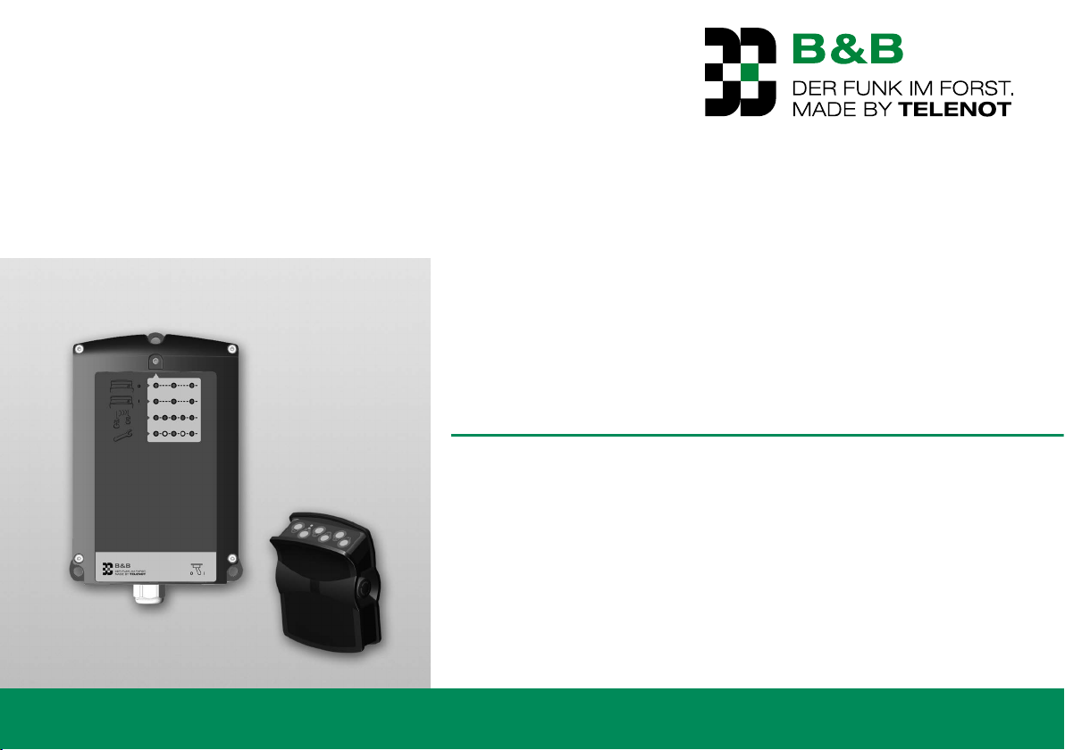
WIRELESS CONTROL
FOR FOREST WINCHES
F6
Version (02)
OPERATING INSTRUCTIONS
english
Page 2

TELENOT ELECTRONIC GMBH
B & B Product Division
Wiesentalstraße 42
73434 AALEN
GERMANY
Tel. +49 7361 946-4813
Fax +49 7361 946-440
E-Mail: [email protected]
Internet: http://www.forest-frequency.com
Translation of the German original operating instructions
2
Page 3

User notes
1 User notes
These operating instructions enable you to use the radio control
for forest winches F6 safely and efficiently.
All stated safety notices and instructions must be observed to
ensure safe working. Furthermore, the local accident prevention
regulations and general safety regulations for the system's area
of use apply.
Illustrations are intended to help you understand the content in
general, and may deviate from the actual design.
Target group
These operating instructions are written for forestry contractors,
private forestry owners and firewood self-harvesters.
Contents
These operating instructions include detailed explanations on
mounting, installation, parameterization, operation, maintenance, and servicing of the radio control.
Use of the operating instructions
Read the complete operating instructions before putting the remote control into operation, and store the operating instructions
in a suitable protective cover at the location of use so they can be
easily accessed.
Do not put the remote control into operation before you have
familiarized yourself with the points of the operating instructions
that are relevant to the purpose for which you intend to use it. In
this way you can prevent errors when operating the system.
Correct use of the product
The radio control provides for convenient and safe remote control
of forest winches. It replaces the wired control of the cable winch.
All common winch types are suitable.
3
Page 4

User notes
Limitation of liability
All technical information in this description has been written
by TELENOT with the utmost care. Nevertheless, errors cannot
be totally excluded. We draw your attention to the fact that we
do not assume any legal responsibility or any type of liability for
consequences that can be traced back to incorrect information.
On account of further product development, the design and
wiring of your product may differ from the information stated
in these instructions. We would be much obliged if you would
inform us of any errors.
We would like to draw your attention to the fact that the software and hardware names and trademarks of the companies
included in the instructions are generally subject to trademark
or patent law.
The manufacturer assumes no liability for damages due to:
Non-observance of the Technical Description
Missuse
Use of non-trained personal
Unauthorized conversions
Technical modifications
Use of non-approved spare parts
General Sales Terms
You can find the General Sales Terms at the TELENOT website at
http://www.telenot.com and in the TELENOT product catalog.
Return faulty devices
To avoid damages during transport, choose stable and robust
packaging (the original packaging, if possible) and, where
appropriate, protective packaging and a box for shipping. Take
into account the weight of the housing, boards, etc. and protect
package contents from shifting. Also protect from the electrostatic discharge ESD. Enclose an error description with the device.
4
Page 5
User notes
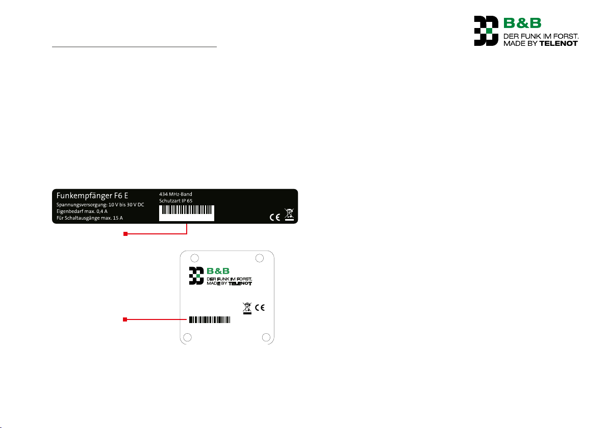
Receiver specification plate
Tr
Serial number
Serial number
Product identification
For inquiries, complaints or parameterization requests, you
must specify the serial number of the device. Based on the serial
number, the manufacturer can identify every component. The
receiver identification can be found on the housing. The transmitter identification is located on the rear of the transmitter on
the belt plate.
Using the serial number the manufacturer can identify every
component.
ansmitter specification plate
Radio control specification plate F6
000000000000031
)XQNVHQGHU
434 MHz Band
Baujahr 2015
000000000000031
TELENOT ELECTRONIC GMBH
Wiesentalstraße 42
73434 Aalen
DEUTSCHLAND
Baujahr 2015
)6
Manufacturer
TELENOT ELECTRONIC GMBH
B & B Product Division
Wiesentalstraße 42
73434 AALEN
GERMANY
Tel. +49 7361 946-4813
Fax +49 7361 946-440
E-Mail: [email protected]
Internet: http://www.forest-frequency.com
5
Page 6
User notes
Explanation of symbols
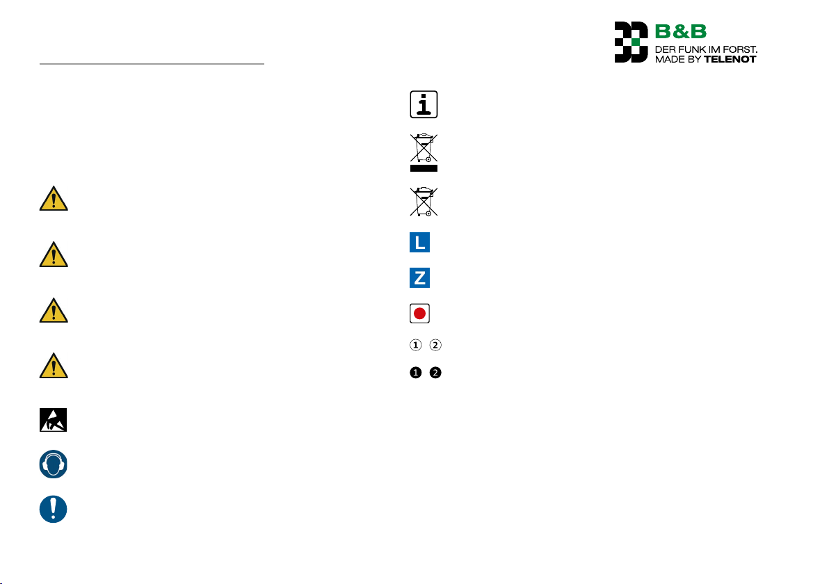
Safety notices are indicated thus:
hazard symbol, signal word, hazard type, and a description of
how to prevent the hazard. Different signal words are used
depending on the hazard degree.
DANGER!
Potentially hazardous situation that can lead to death or
very serious injuries.
WARNING!
Potentially hazardous situation that can lead to death or
serious injuries.
CAUTION!
Potentially hazardous situation that can lead to minor
or light injuries.
NOTICE!
Potentially hazardous situation that can lead to property
damage.
Component at risk of ESD (ESD = electrostatic discharge
(eng), elektrostatische Entladung (ger))
NOISE!
Hearing damage due to noise!
Tips, recommendations, useful information
Disposal instruction
Instructions for disposal for hazardous batteries and
rechargeable batteries
Delivery
Accessories, useful add-ons for optimum product use
Parameterizable function
Legend
Sequence of action
Important notice, order
6
Page 7

Table of content
2 Table of content
1 User notes . . . . . . . . . . . . . . . . . . . . . . . . . . . 3
2 Table of content . . . . . . . . . . . . . . . . . . . . . . .7
3 Safety notes . . . . . . . . . . . . . . . . . . . . . . . . . . 9
3.1 Responsibility of the owner of the system . . . . . . . 9
3.2 Responsibility of the user . . . . . . . . . . . . . . . . . . 9
3.3 Special risks . . . . . . . . . . . . . . . . . . . . . . . . . . 11
3.3.1 Defective control elements . . . . . . . . . . . . . . . 11
3.3.2 Noise . . . . . . . . . . . . . . . . . . . . . . . . . . . . . 11
3.3.3 Short circuit . . . . . . . . . . . . . . . . . . . . . . . . . 11
3.4 Transport, packaging materials and storage . . . . . 11
3.4.1 Safety notes for transport . . . . . . . . . . . . . . . . 11
3.4.2 Handling packaging materials . . . . . . . . . . . . . 12
3.4.3 Storage of packing pieces . . . . . . . . . . . . . . . . 12
3.5 Storing and handling the transmitter
rechargeable battery eneloop®¹ (optional) . . . . . . 12
3.6 Conduct in the event of danger and accidents . . . 13
4 Delivery . . . . . . . . . . . . . . . . . . . . . . . . . . . 14
5 System overview . . . . . . . . . . . . . . . . . . . . . . 15
6 Function overview . . . . . . . . . . . . . . . . . . . . . 16
6.1 Transmitter . . . . . . . . . . . . . . . . . . . . . . . . . . 16
6.2 Receiver . . . . . . . . . . . . . . . . . . . . . . . . . . . . 17
7 Device Features . . . . . . . . . . . . . . . . . . . . . . . 17
7.1 Radio control F6 . . . . . . . . . . . . . . . . . . . . . . . 17
7.2 General features . . . . . . . . . . . . . . . . . . . . . . . 18
7.3 Transmitter features . . . . . . . . . . . . . . . . . . . . 18
7.4 Receiver features . . . . . . . . . . . . . . . . . . . . . . 18
8 Functional Description . . . . . . . . . . . . . . . . . . 18
8.1 Structure . . . . . . . . . . . . . . . . . . . . . . . . . . . 18
8.1.1 Transmitter F6 S . . . . . . . . . . . . . . . . . . . . . . 18
8.1.2 F6 receiver . . . . . . . . . . . . . . . . . . . . . . . . . . 19
8.2 Functions . . . . . . . . . . . . . . . . . . . . . . . . . . . 20
8.2.1 Pull drum . . . . . . . . . . . . . . . . . . . . . . . . . . 20
8.2.2 Release brake . . . . . . . . . . . . . . . . . . . . . . . 20
8.2.3 Gas adjustment . . . . . . . . . . . . . . . . . . . . . . 21
8.2.4 Active emergency call function
("Active emergency") . . . . . . . . . . . . . . . . . . . 21
8.2.5 Changing the radio channel . . . . . . . . . . . . . . 23
9 Accessories . . . . . . . . . . . . . . . . . . . . . . . . . 24
10 Mechanical structure . . . . . . . . . . . . . . . . . . . 25
10.1 Transmitter F6 S . . . . . . . . . . . . . . . . . . . . . . . 25
10.2 Receiver F6 E . . . . . . . . . . . . . . . . . . . . . . . . . 25
11 Mounting . . . . . . . . . . . . . . . . . . . . . . . . . . 26
11.1 Transmitter F6 S . . . . . . . . . . . . . . . . . . . . . . . 26
11.1.1 Carrying on the body . . . . . . . . . . . . . . . . . . . 26
11.1.2 Mounting with bracket for transmitter . . . . . . . 27
11.2 Receiver F6 E . . . . . . . . . . . . . . . . . . . . . . . . . 27
11.2.1 Mounting location requirements . . . . . . . . . . . 27
11.2.2 Mounting of F6 E receiver . . . . . . . . . . . . . . . . 28
12 Connections and Interfaces . . . . . . . . . . . . . . . 29
12.1 Position . . . . . . . . . . . . . . . . . . . . . . . . . . . . 29
12.2 Connection type . . . . . . . . . . . . . . . . . . . . . . . 29
12.3 Connection configuration . . . . . . . . . . . . . . . . . 30
12.3.1 Socket 1 . . . . . . . . . . . . . . . . . . . . . . . . . . . 30
12.3.2 Socket 2 . . . . . . . . . . . . . . . . . . . . . . . . . . . 31
13 Installation . . . . . . . . . . . . . . . . . . . . . . . . . 32
14 Wiring diagrams . . . . . . . . . . . . . . . . . . . . . . 33
7
Page 8

Table of content
15 Parameterization . . . . . . . . . . . . . . . . . . . . . . 34
15.1 Who performs the parameterization? . . . . . . . . . 34
16 Commissioning . . . . . . . . . . . . . . . . . . . . . . . 34
16.1 Requirements . . . . . . . . . . . . . . . . . . . . . . . . 34
16.2 Preparation . . . . . . . . . . . . . . . . . . . . . . . . . . 34
16.2.1 Receiver connection . . . . . . . . . . . . . . . . . . . . 34
16.3.1 Fitting batteries/rechargeable batteries
in the transmitter . . . . . . . . . . . . . . . . . . . . . 35
16.3 Functional test . . . . . . . . . . . . . . . . . . . . . . . . 35
16.4 Fault-free operation . . . . . . . . . . . . . . . . . . . . . 36
16.4.1 Commissioning check list . . . . . . . . . . . . . . . . 37
17 Operation . . . . . . . . . . . . . . . . . . . . . . . . . . 38
16.5 Safety notices for operation . . . . . . . . . . . . . . . 38
17.1 Receiver F6 E . . . . . . . . . . . . . . . . . . . . . . . . . 40
17.2 Transmitter F6 S . . . . . . . . . . . . . . . . . . . . . . . 40
17.2.1 LED indications on the transmitter F6 S . . . . . . . 41
17.2.2 Release brake . . . . . . . . . . . . . . . . . . . . . . . 42
17.2.3 Permanent release . . . . . . . . . . . . . . . . . . . . 42
17.2.4 Pull drum . . . . . . . . . . . . . . . . . . . . . . . . . . 43
17.2.5 Gas+ . . . . . . . . . . . . . . . . . . . . . . . . . . . . . 43
17.2.6 Gas– . . . . . . . . . . . . . . . . . . . . . . . . . . . . . 44
17.2.7 Triggering "Activeemergency" . . . . . . . . . . . . . 44
17.2.8 Reset "Active emergency" . . . . . . . . . . . . . . . . 46
17.3 Eliminate fault states . . . . . . . . . . . . . . . . . . . . 47
18 Maintenance and service . . . . . . . . . . . . . . . . . 48
18.1 Recommended maintenance interval . . . . . . . . . 48
18.2 Scope of maintenance . . . . . . . . . . . . . . . . . . . 48
18.2.1 Cleaning the transmitter and receiver . . . . . . . . 49
18.2.2 Batteries . . . . . . . . . . . . . . . . . . . . . . . . . . . 49
18.2.3 Rechargeable batteries (optional) . . . . . . . . . . . 49
18.2.4 Changing fuses in the receiver F6 E . . . . . . . . . . 50
19 Disassembly and disposal . . . . . . . . . . . . . . . . 52
19.1 Decommissioning . . . . . . . . . . . . . . . . . . . . . . 52
19.2 Disassembling the receiver F6 E . . . . . . . . . . . . . 52
19.3 Disposal . . . . . . . . . . . . . . . . . . . . . . . . . . . . 52
20 Technical Data . . . . . . . . . . . . . . . . . . . . . . . 53
21 Declaration of conformity . . . . . . . . . . . . . . . . 55
8
Page 9
Safety notes
3 Safety notes
The operating instructions provide important information for
handling the device. All stated safety notices and instructions
must be observed to ensure safe working.
3.1 Responsibility of the owner of the system
The receiver may only be connected by a specialist according
to the pin assignment diagram enclosed.
The radio control may only be operated in a technically per-
fect state. In the event of faults and defects that can impair
safety, the system must be switched off immediately and
repaired by a qualified professional.
If a radio control is used you must make sure that it does not
interfere with the other systems around it and it itself is not
interfered with by them.
Adjustment of speed from the radio control is only per-
missible if it can be guaranteed from a structural point of
view that the cable intake speed does not exceed 0.6m/s
and that the change in cable intake speed is not more than
20percent.
Conduct regular visual inspections to allow damaged cables,
plugs, and other equipment necessary to ensure safety to be
repaired prior to starting work.
People whose responsiveness is impaired by the influence of
medication, alcohol, or drugs may not put the radio control
into operation, operate, maintain, or repair it.
People carrying medical devices should check the compatibi-
lity of their devices with the radio control that is constructed
according to EN 62479.
3.2 Responsibility of the user
DANGER!
Danger from vehicles tipping over
Ensure that the required stability of the vehicle is
provided. Check the ground.
DANGER!
Danger from pulling up tree trunks
Do not touch the towing cable during operation!
Nobody should be located around the intake zone of the
cable winch!
DANGER!
Danger from tree trunks falling down
Keep a safe distance from the cable winch.
9
Page 10
Safety notes
DANGER!
Danger from unintentional triggering of functions or
starting up
Ensure that no unintended actuation of the transmitter
can be caused by items of clothing and similar items.
Switch the transmitter off during break times and at
the end of work and secure it against unauthorized
access (e.g. from children).
Make sure that the receiver is unplugged while driving.
DANGER!
Danger from cutting off and restoration of the power
supply for the transmitter/receiver
Nobody should be located around the intake zone of the
cable winch!
Keep a safe distance from the cable winch.
Requirements for safe operation
Wear protective work clothing suitable for the activity and
the deployment location (PPA).
Before switching on the radio control, ensure that nobody
could be put at risk from operation.
Always work with a direct line of sight to the machine and
proceed with particular caution if you are not yet familiar
with operating the radio control.
When changing location, make sure that you do not acci-
dentally reverse the directions of movement of the cable.
To ensure that a work phase ends and consequently safe
conditions can be established on site in the highly unlikely
event of total failure of the battery, it is recommended that
you always carry two spare batteries and the manual control for the winch with you in the vehicle.
The stop and emergency call switch on the transmitter
only affects the winch and is not to be confused with the
machine's emergency-off.
Follow the instructions in the section "Maintenance".
Only use the radio control within the climatic, environmen-
tal conditions that are specified in the section "Technical
data".
In addition to generally applicable regulations for accident
prevention, the local regulations should also be observed.
10
Page 11
Safety notes
3.3 Special risks
3.3.1 Defective control elements
CAUTION!
Residual risk!
Even if the operator follows the procedures correclty,
a residual risk still applies. Example: The operator
deactivates the "Pull" command. Due to a mechanical
blockage, however, the command continues to be
executed.
Keep an eye on your working environment at all times
so that you can react quickly and prudently even in
unexpected hazardous situations.
3.3.2 Noise
CAUTION!
Hearing damage due to noise!
When you are working in the vicinity of audible alarm
messages (> 85 dBA), wear hearing protection.
Remain in the vicinity of audible warning devices only
for as long as required.
3.3.3 Short circuit
WARNING!
Fire hazard from short circuits!
In the event of a short circuit, very high currents may
occur which could, for example, heat up plug connections and cables considerably. A fire could potentially
result.
The supply voltage of the receiver must be protected
with a 15 A fuse to prevent the risk of fire.
3.4 Transport, packaging materials and storage
3.4.1 Safety notes for transport
NOTICE!
In the case of incorrect transportation, substantial property damage can arise.
Be careful when you unload the packing pieces or by
transporting them within your company premises.
Observe the symbols on the packaging.
Make sure that you are ready to start mounting before
you remove the packaging.
Inspection of delivery
When you receive the delivery, immediately check it for
completeness and transport damage.
If a delivery has transport damage that can be recognized
externally, do not accept the delivery – or if you accept the
delivery, do so under reservation only. Tender a complaint.
11
Page 12

Safety notes
3.4.2 Handling packaging materials
Packaging materials are valuable raw materials which can often
be re-used or recycled.
Dispose of the packaging materials in an environmentally
friendly manner.
Observe the locally applicable waste disposal regulations.
Contract an expert company for disposal, if necessary.
DANGER!
Risk of suffocation and injury for children due to
packaging materials
Keep packaging materials away from children.
3.4.3 Storage of packing pieces
Store packing pieces under the following conditions:
Do not store in the open air.
Store in dry and dust-free conditions.
Do not expose to any aggressive media.
Protect from direct sunlight.
Avoid mechanical vibrations.
Storage temperature: see technical data
Relative humidity: see technical data
In the case of storage for longer than 3 months, inspect the
general state of all parts and packaging regularly. If necessary, recondition or replace the packaging.
3.5 Storing and handling the transmitter rechargeable battery eneloop®¹ (optional)
Batteries gradually lose capacity with age and operating times
become shorter.
If handled properly, the lifetime of the battery is around 1,500
charge and discharge cycles. After further charging cycles and at
temperatures below 0°C the capacity can drop considerably.
Only recharge the battery when it is empty. If it is charged
after only a short period of operation, it shortens the service
life.
Do not charge the rechargeable battery at temperatures
below 0°C or above +40°C. The rechargeable battery
should preferably be charged within a temperature range of
+10°C to +30°C.
If the rechargeable battery has not been used for an exten-
ded period, charge it before using it.
The transmitter switches off automatically if it is not used for
longer than the parameterized time (e.g. 20minutes), or if the
rechargeable battery is discharged. This feature reliably prevents
harmful deep discharging.
¹ eneloop ® is a trademark of Panasonic (formerly of
Sanyo).
eneloop® battery technology enables up to 50 hrs of
continuous transmission without recharging; even
if – as occurs regularly in privately owned forests –
instances of use are separated by weeks or months.
eneloop® batteries only lose 15% of capacity per year
(as opposed to up to 100% in conventional quality
batteries)
12
Page 13

Safety notes
CAUTION!
Incorrect use of rechargeable batteries can cause eye
injuries or property damage!
Only use the batteries in the devices that are intended for
them (battery technology and type).
Only charge the rechargeable batteries in charging devices
that have either been supplied or recommended by the
manufacturer.
Keep the unused batteries far away from metallic objects
which could cause bridging of the contacts.
Fluid can emerge from the battery in the event of incorrect
usage. Avoid contact with it. In the event of accidental contact with the battery fluid, rinse with water. If battery fluid
gets in the eyes also seek medical attention.
In accordance with the battery ordinance, batteries
must not be disposed of with domestic waste!
Batteries purchased from TELENOT can be returned free
of charge, where they are disposed of properly.
3.6 Conduct in the event of danger and accidents
Preventive measures
You must always be prepared for the case of accidents or
fire.
Store the first-aid equipment (medical kit, blankets, etc.)
within easy reach.
Store the fire extinguisher within easy reach.
Make sure that personnel are familiar with accident notifi-
cation, first-aid, and rescue equipment.
Keep access routes for emergency rescue vehicles free.
In the event of problems: handle correctly!
Put the device out of operation immediately.
Rescue all persons from the danger zone.
Initiate first-aid measures.
Inform the authorized personell at the location of use.
Notify a doctor and/ or the fire department.
Clear access routes for rescue vehicles.
13
Page 14

Delivery
4 Delivery
Art.-No. Name Delivery
109536040 Radio control F6 − Transmitter F6 S
− Receiver F6 E with connection cable and plug
− Pin assignment plan, valid for your winch
− Accessories kit with: 4 AA batteries, waist belt, 3runner-bonded metal buffer for receiver, B&B ball-point pen
− Original operating instructions F6
− Translation of the original operating instructions in German language F6
into the language of the destination country
− Optional: 4 AA NiMH eneloop® rechargeable batteries, 230V rechargeable
battery charger
− Optional: Chest belt
14
Page 15
System overview
5 System overview
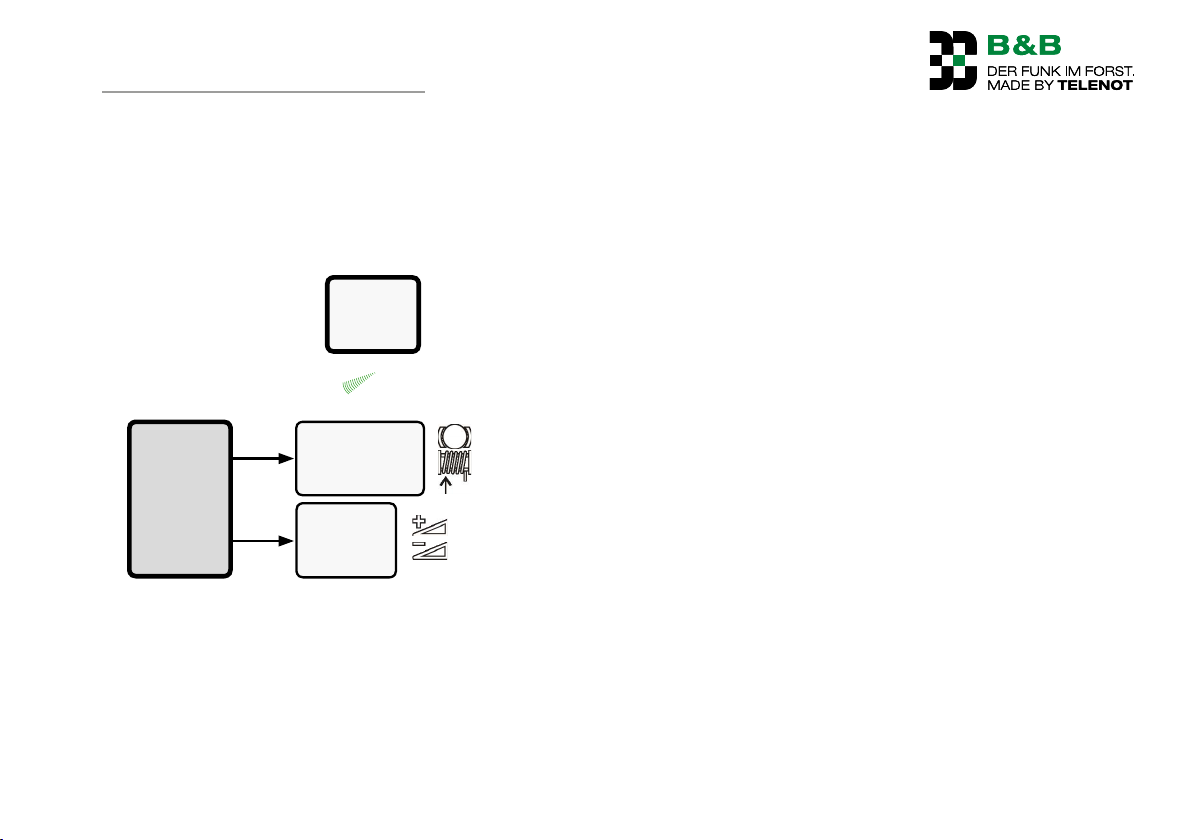
The radio control F6 is used for wireless activation of cable
winches. The radio control F6 can be used to control single-drum
winches (ET) of all types.
Transmitter
F6 S
Winch
release brake /
Receiver
F6 E
Overview: Connecting the F6 to a machine
pull drum
Gas
+/–
15
Page 16
Function overview
6 Function overview
The radio control F6 was developed specifically for the challenging requirements in the forestry sector. The high-quality radio
electronics in a robust housing make the F6 an ideal controller
for professional skidding and pulling work.
The radio control is suitable for use on forestry vehicles with
permanently attached cable winches and for 3-point cable
winches on agricultural tractors.
6.1 Transmitter
Transmitter F6 S
The transmitter is small, light and easy to handle and you can
carry it conveniently on your waist, midriff or chest (optional).
The ergonomic design of the operating panel allows for fatiguefree working and safe operation, also if you are wearing gloves.
The electronics are housed in a rubber-reinforced enclosure
made of glass fiber-reinforced polyamide and protected against
the penetration of dust and water jets (protection class IP65).
The antenna is integrated in the housing. The control elements are surrounded by a protective collar that is capable of
withstanding high mechanical loads. Full batteries or charged
rechargeable batteries (optional) provide sufficient power for
50hours of continuous transmission in normal operation mode.
16
Page 17
Device Features
6.2 Receiver
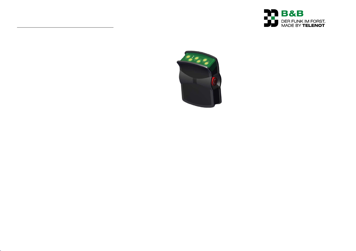
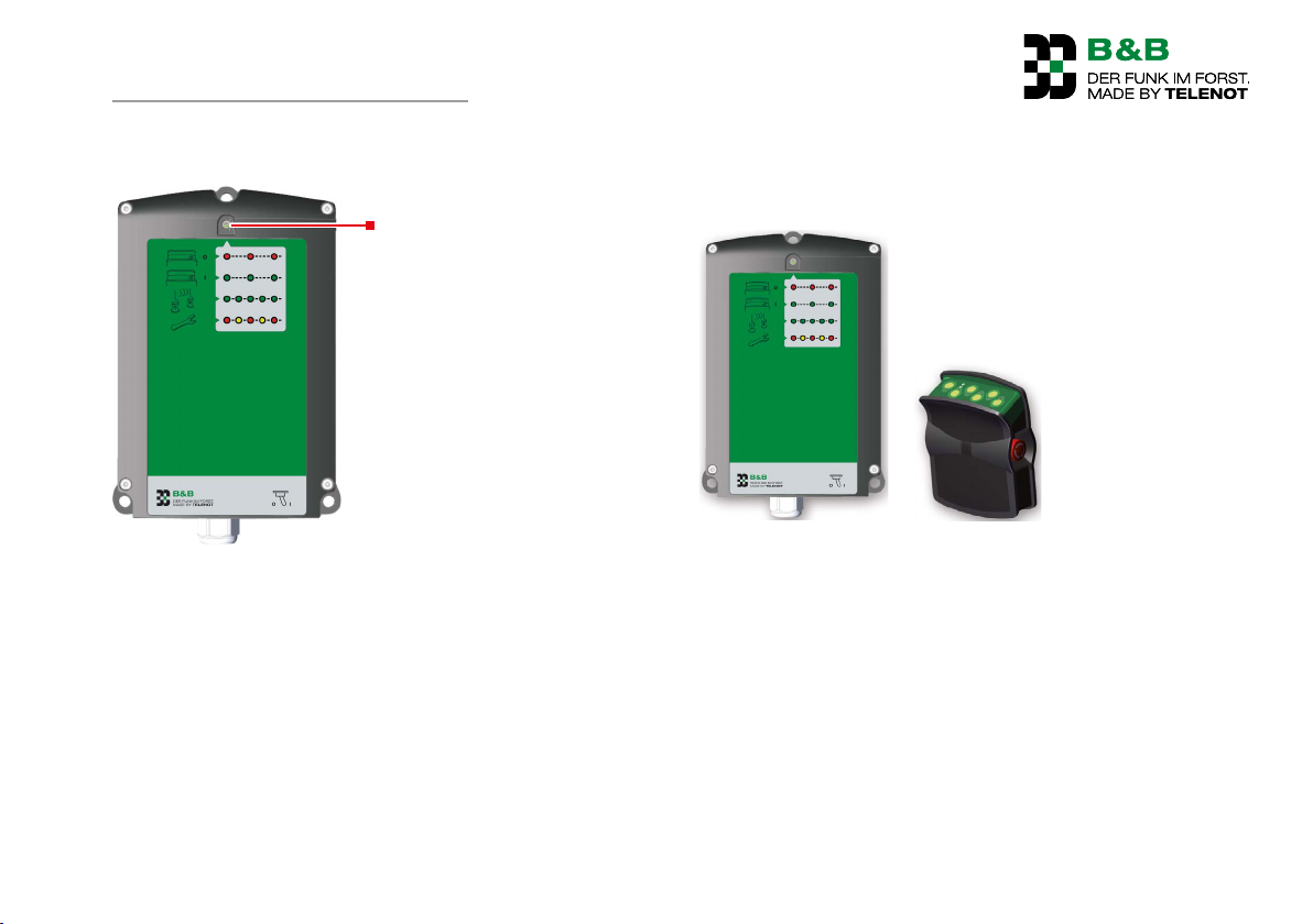
Diagnostics LED
Receiver F6 E
The receiver has its own diagnostics LED which indicates the
status of important output functions and system messages by
lighting up in a specific color (red, green, orange) and a specific
blink rhythm. This permits rapid on-site assessment of the status
of the radio control.
The receiver electronics are contained in a robust polyamide
housing and protected against dust and water jets (protection
toIP65).
7 Device Features
7.1 Radio control F6
Radio control F6
Ready-to-operate set F6 for single-drum winches
Functions:
Pull
Brief and permanent brake release
Gas +/–
17
Page 18
Functional Description
7.2 General features
Operationally safe function on the 70-cm ISM band
Bidirectional radio technology
3 working channels
Individual adjustments to the special circumstances and
types of operation of a wide range of winch operating modes.
Operating temperature –20°C to +60°C
7.3 Transmitter features
Ergonomically designed operation panel
Robust, glass fiber-reinforced housing with surrounding
protective rubber edges
High-quality membrane keypad for long service life
Stop and emergency switch with active emergency call
function
Energy-saving battery concept (2 AA batteries fitted, 2 spare
AA batteries) for 50 hours of operation with full batteries or
charged rechargeable batteries (optional)
eneloop® AA exchangeable replaceable battery system
(optional)
Protection type IP65
Dimensions (W x H x D) 116 x 161 x 61 mm
Weight approx. 600 g with batteries/rechargeable batteries
(without belt)
7.4 Receiver features
Shock-proof housing made from PC/ABS polyamide
Diagnostics LED
Protection type IP65
Dimensions (W x H x D) 152 x 218 x 51/66 mm
Operating voltage +10V to +30V DC
Weight approx. 670 g
18
8 Functional Description
8.1 Structure
8.1.1 Transmitter F6 S
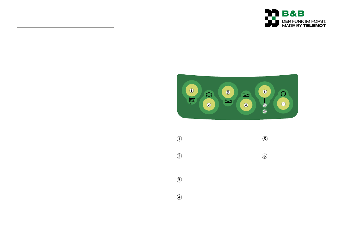
Operating possibilities for transmitter F6 S
Button 1
− Pull drum
Button 2
− Release brakes (brief)
− Permanent release (long)
Button 3
− Gas+
Button 4
− Gas–
Details: See operation
Button 5
− Switch on
Button 6
− Switch off
Page 19
Functional Description
8.1.2 F6 receiver
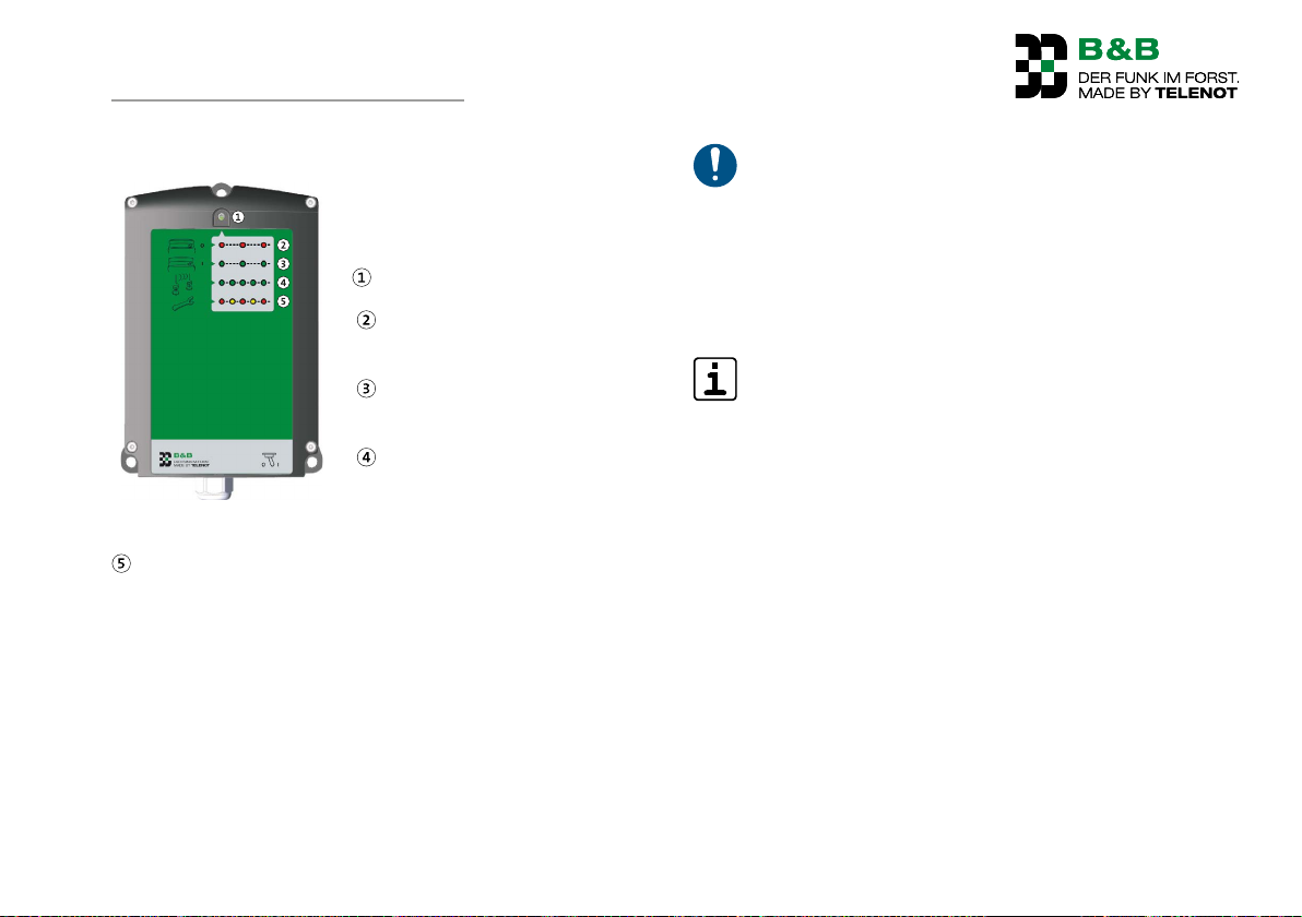
Diagnostics LED (red, green, orange)
Diagnostics LED flashing red:
Transmitter is switched off
Diagnostics LED flashing green:
Transmitter is switched on
Diagnostics LED blinking green:
radio reception active (command is received)
Display F6 receiver
Diagnostics LED blink sequence red, orange:
- Siren monitoring has triggered
--> Check fuse Si5 and supply line to the siren
Diagnostics LED blink sequence red, red, orange, orange:
- Monitoring of relay outputs has triggered
--> Check main fuse Si1 and relay outputs
Diagnostics LED blink sequence red, red, red, orange,
orange, orange:
- Device malfunction
--> Contact service
What to do in case of a device malfunction
In the case of an error in the safety critical function or
the internal self-monitoring function, you must cease
operation of the system immediately!
The system must be sent in to the factory for repairs. To
specify faults please use the form enclosed. A corresponding response form is available for download on our
website at http://www.funk-im-forst.de/service.
All outputs except for "EMERGENCY" are monitored for
proper functioning or short circuits and in case of errors
the diagnostics LED will give indications. The "siren"
output is not monitored on delivery, but can be parameterized for being monitored.
Do not apply any voltage to the outputs!
19
Page 20
Functional Description
8.2 Functions
8.2.1 Pull drum
To start the "Pull drum" function (cable intake by the
winch), press and hold the button and release the button to stop the function (jog mode).
8.2.2 Release brake
To start the "Release brake" function (release brake on
the winch), press and hold the button and release the
button to stop the function (jog mode).
Permanent release
If you hold down the button for longer (longer than the permanent
release time parametrized at the factory), the brake is permanently
released until you press the button again (release brake or pull
drum).
If the transmitter is not operated for longer than the parameterized stand-by time (factory setting 20 min.), the "permanent
release" function is automatically exited and the brake is applied
again.
The following functions are parametrized at the factory (depending on winch type):
Single functions (EF):
With the "Pull drum" command only the output "Pull drum" is
activated. The brake of the winch releases automatically.
Dual function (DF):
Activating the "Pull drum" command also activates the "Release
brake" command.
Depending on the winch type, the operating mode and time for
permanent release are parameterized at the factory:
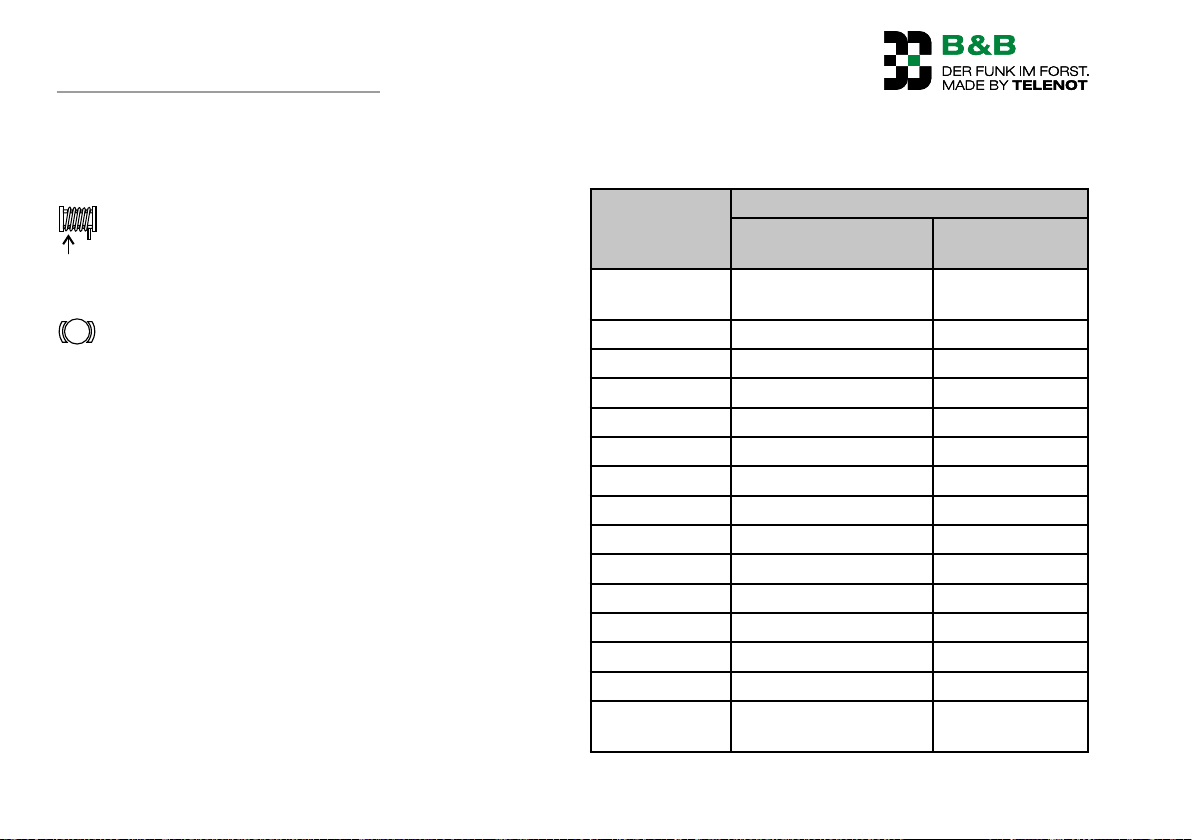
Winch type Operation mode
Single function (EF) /
dual function (DF)
AMR/BGU/
Uniforest
Farmi EF 1.5 s
Fransgard EF 3.5 s
GVS DF 1.5 s
Holzknecht EF 1.5 s
Igland DF 1.5 s
KMB EF 3.5 s
Krpan/Oehler EF 3.5 s
Maxwald EF 1.5 s
Pfanzelt DF 1.5 s
Ritter (old) DF 1.5 s
Ritter KWF DF 1.5 s
S&R DF 1.5 s
Tajfun EF 3.5 s
Werner/
Glogger
EF 3.5 s
DF 1.5 s
Duration of permanent release
20
Page 21

Functional Description
8.2.3 Gas adjustment
Gas continuous (GS)
To start the "Gas +" function, press and hold the button
and release the button to stop the function (jog mode).
To start the "Gas -" function, press and hold the button
and release the button to stop the function (jog mode).
Application:
The motor speed is controlled, for example, on the throttle rods
upwards (Gas +) or downwards (Gas –) by a lifting spindle motor
(e.g. WARNER M-Track 1 gas actuator).
For machines without mechanical gas-adjustment capability,
the Propgas control module PGS01 can be used. Depending on
the function Gas + / Gas –, the module outputs a variable DC
voltage of between 0–4.8 V to the motor control unit.
Gas simple (GE)
Can be parameterized at the factory
The "Gas +" function switches on the supply voltage at
the "Gas +" output when you tap the button.
The "Gas -" function switches off the supply voltage at
the "Gas -" output when you tap the button.
Application:
With "Gas +", a fixed, higher motor speed is set.
With "Gas –", a fixed, lower motor speed is set.
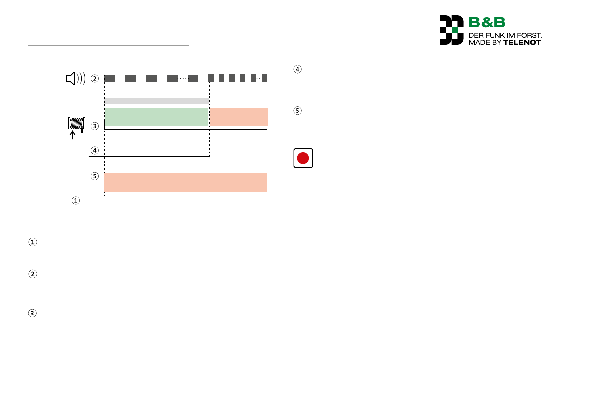
8.2.4 Active emergency call function ("Active emergency")
The active emergency call function is used to summon help if
the person involved in an accident is still capable of triggering
an active emergency call. This function is useful if people located
in the vicinity can be alerted via a connected loud horn or an
emergency call TD is installed to alert other assistance-providing
persons.
All active commands are ended and no other commands accepted (command lock).
The active emergency call is triggered voluntarily by pressing the
stop and emergency call switch on the transmitter.
The function "Active emergency" is switched on at the factory
and cannot be switched off.
21
Page 22
Functional Description
s1
Siren
Commands
"Emergency"
output
Reset
alarms
"Active emergency" trigger
Active emergency sequence
2 s2
30 s
Pre-alarm Main alarm
With "Stop emergency" off and O + I (switch
off/on)
s
To trigger "Active emergency", press the stop and emergency call switch
First the pre-alarm (2 s sound, 2 s pause) and after 30 s the
main alarm (1 s sound, 1 s pause) through the siren; status
LED blinks green rapidly (battery charged).
Already activated commands (e. g. pull drum) are switched
off; other dangerous commands are blocked.
If you turn the stop and emergency call switch, new commands are accepted again; however, the alarm continues.
1 s
On expiry of the pre-alarm time, the "Emergency" output is
switched (e. g. for activating an emergency-call transmission
device).
By turning the stop and emergency call switch and then
switching off and on the transmitter, you can reset the
alarm during the pre-alarm and the main alarm.
The "Siren" output is not monitored with the factory
setting; but it can be parameterized to be monitored.
22
Page 23

Functional Description
8.2.5 Changing the radio channel
If there are faults due to radio controls being operated in parallel,
the radio channel can be changed (factory setting: channel2).
The radio control F6 operates in the 70 cm ISM band and can be
operated on 3 radio channels:
Channel 1: 434.175 MHz
Channel 2: 434.475 MHz
Channel 3: 434.675 MHz
Switch off transmitter, receiver must be under voltage
Press and hold a button on the transmitter for longer than
5 seconds, the operating LED lights up
Changing to next channel up
The status LED goes off after a successful channel change
DANGER!
Danger from accidental operation of machinery
When multiple radio controls are used in parallel, provide the transmitters and vehicles (receivers) with unique
number stickers in order to prevent confusion, and thus
accidental operation.
23
Page 24
Accessories
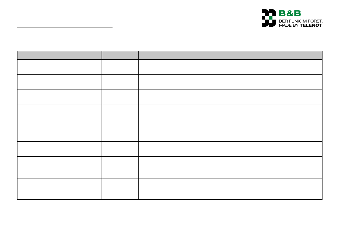
9 Accessories
Name Art.-No. Description
NiMH eneloop®
AA battery
A-LG12VZA battery charger for
cigarette lighter
230V battery charger A-LG 230V 109536081 For the gentle charging of up to 4 eneloop® batteries AA size at the 230-V-
Waist belt for LG-S transmitter 109535824 Waist belt for transmitter F10, F6, F9, F5, F1011, F1008 and F1007.
Chest belt for transmitter BTG-S 109536083 Carrying strap for chest carrying method for mounting in the waist belt for
Bracket for transmitter HG1 109536084 Bracket for the F10 S transmitter for assembly in a tractor or as a wall bracket
WARNER M-Track 1 gas actuator 109536085 Lifting spindle motor for continuous gas regulation for tractors and forestry
Propgas control module PGS01 109535898 Additional module for controlling the continuous gas function for tractors
109536082 4NiMH eneloop®
AA-size batteries in a plastic box
109536080 For the mobile charging of 2 AA batteries at the 12-V terminal of the cigarette
lighter
mains-connection
40-mm wide, 1.35-m long with plastic snap buckle.
transmitters F10, F6, F5, F9, F1011, F1008 and F1007. 30-mm wide with plastic snap buckle. Carrying strap can only be used together with the waist belt.
in a garage, for example. Material steel plate, smooth, matte
machines with mechanical gas control. Sealed aluminum housing in compact
design.
without mechanical gas adjustment capability. The module outputs a variable
DC voltage of between 0–4.8 Volts; supply voltage 12 V.
24
Page 25
Mechanical structure
10 Mechanical structure
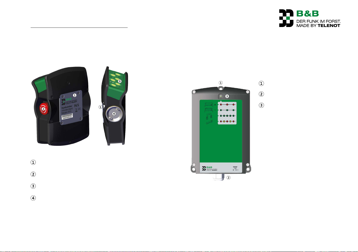
10.1 Transmitter F6 S
Mechanical structure of F6 transmitter
Belt plate
Stop and emergency switch
Operation buttons
Battery compartment screw cap
The transmitter of the radio control F6 comprises a plastic
housing (polyamide 66-GF+TPE) with protection type IP65. The
belt plate for passing through the waist belt is located on the
rear of the device. The stop and emergency call switch is located
- as viewed by the operator - on the left side of the device and
the battery / rechargeable battery compartment with screw
cover is on the right side.
Operation is by means of the buttons on the top side.
10.2 Receiver F6 E
Mounting clips
Cable screw thread
Diagnostics LED
Mechanical structure of F6 receiver
The receiver of the radio control F6 comprises a two-part plastic
housing (PC / ABS) with protection type IP65. Three mounting
tabs are provided for monting. A diagnostics LED displays different operating states and faults. The cable entry of the 2.7m
long connection cable is provided by a cable screw thread.
25
Page 26
Mounting
11 Mounting
11.1 Transmitter F6 S
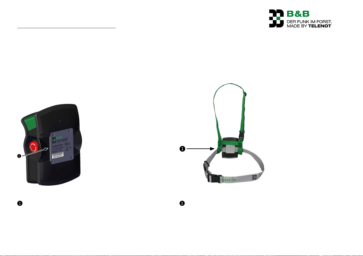
11.1.1 Carrying on the body
Carrying the transmitter on your hip
You can carry the transmitter of the radio control F6 on your hip
using the waist belt (included in the delivery).
Mounting of waist belt on transmitter F6 S
Feed the waist belt under the belt plate.
Carrying the transmitter on your chest
You can carry the transmitter of the radio control F6 on your
chest using the waist belt and chest belt. (The waist belt is included in the delivery and the chest belt is available as optional
equipment).
Installation of chest belt onto waist belt
Feed the waist belt through the chest belt and under the
belt plate.
26
Page 27
Mounting
50 mm
Ø 5 mm
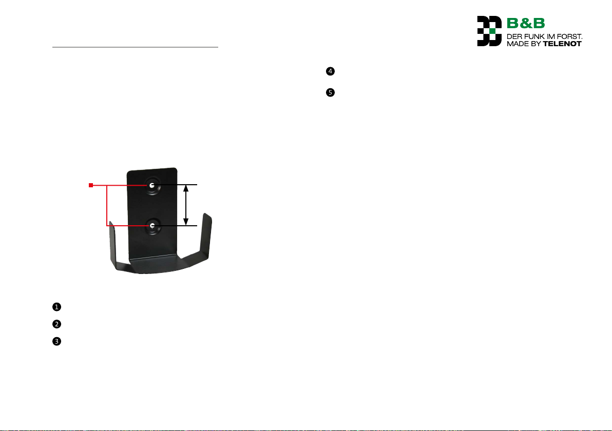
11.1.2 Mounting with bracket for transmitter
The transmitter of the radio control F6 can be attached to the
wall or to the vehicle using the bracket for transmitter HG1.
Dimensions (W x H x D) 110x112x48mm
Material: Steel plate
Color: RAL 9005 jet black, smooth, matte
Art. No. 109536084
Transmitter bracket installation
Mark the fixing holes using the dimensional sketch.
Drill appropriate holes for the screws used.
Depending on the surface, use for example sheet metal
screws / screws and wall plugs. The max. diameter of the
screws may not exceed 4.5mm.
Screw the bracket tight.
The transmitter can now be placed in the bracket and taken
out again.
11.2 Receiver F6 E
11.2.1 Mounting location requirements
The receiver must be tightly bolted to the vehicle!
To achieve the broadest range possible, the ideal mounting
location is at the rear of the vehicle.
Avoid mounting in completely closed metal housings to
ensure the unhindered emission of the antenna.
Avoid mounting in direct proximity to other radio systems
or other electronic devices that could cause EMC faults.
Avoid mounting in places directly exposed to atmospheric
conditions.
Select a mounting location so that a vertical installation
(cable gland downwards) and cable infeed from below are
possible.
27
Page 28
Mounting
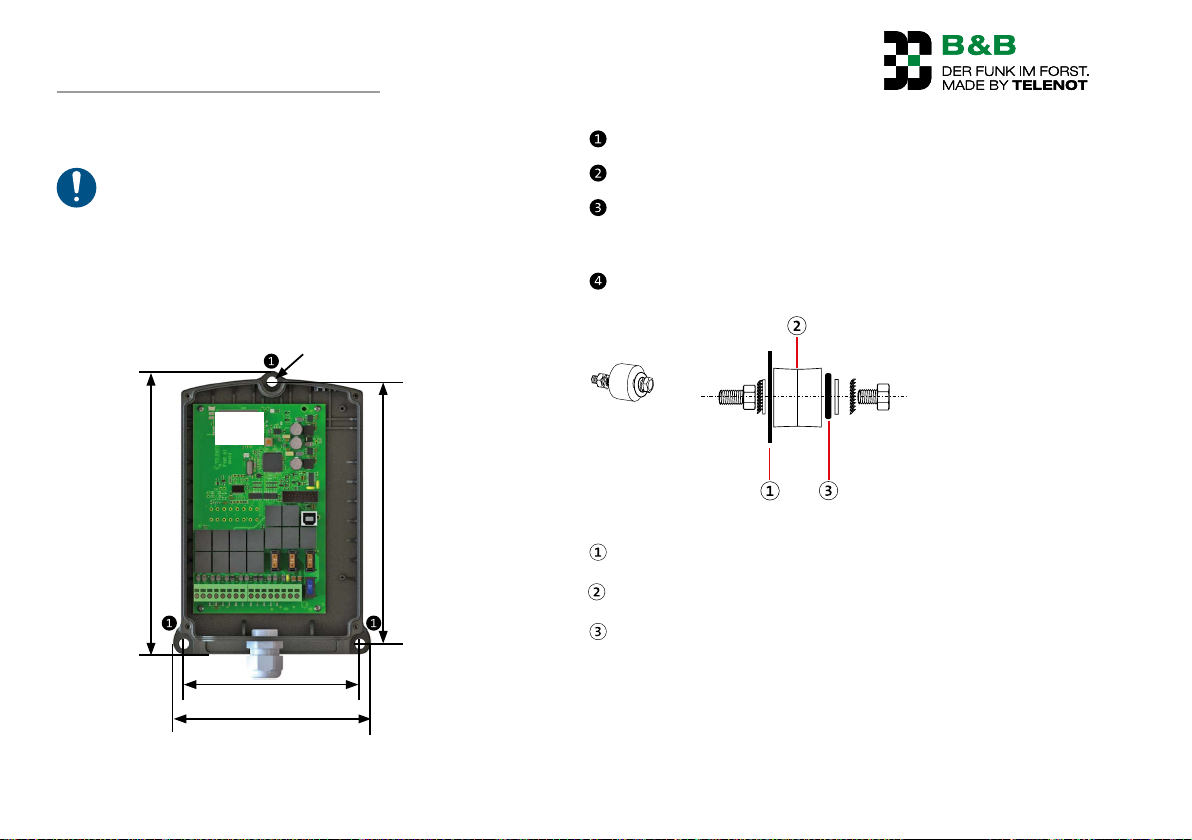
11.2.2 Mounting of F6 E receiver
Mount the receiver vertically with the gable gland
downwards. The antenna must be removed from metal
surfaces as far as possible in order to achieve optimum
radio range. Use the 3 runner-bonded metal buffers
supplied with the package to install the receiver. These
provide a minimum gap from metal surfaces and dampen vehicle vibration.
Ø 8 mm
Antenna
217,5 mm
135,5 mm
201 mm
Mark the fixing holes using the dimensional sketch.
Drill appropriate holes for the screws used.
Fix the receiver housing to the vehicle with the help of the
3runner-bonded metal buffers as shown in the following
illustration.
Tighten all screws.
Rubber-bonded metal buffer mounting
Vehicle plate
Runner-bonded metal buffer
Receiver housing
Mounting of F6 E receiver
28
152 mm
Page 29
Connections and Interfaces
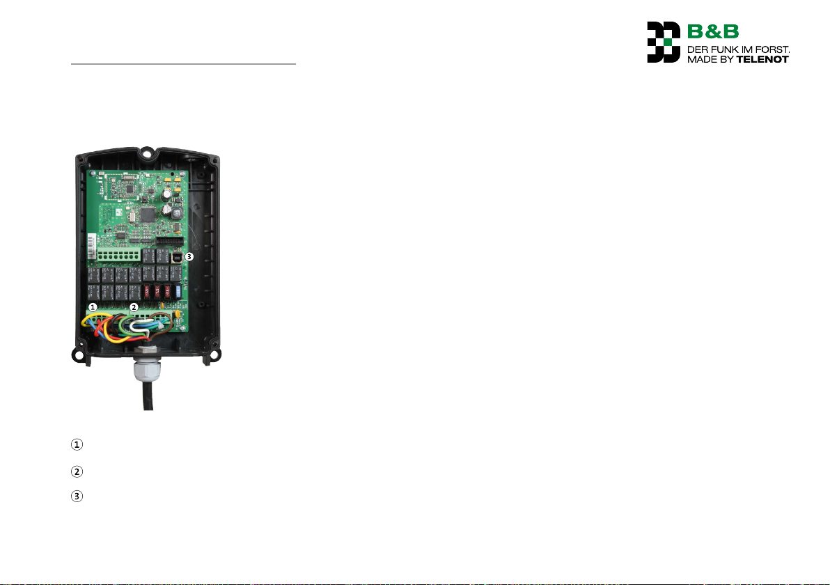
12 Connections and Interfaces
12.1 Position
Position F6 E connections
Socket 1 (BU1): 8-pole terminal block
Socket 2 (BU2): 8-pole terminal block
Socket 3 (BU3): USB socket
12.2 Connection type
The connections for socket 1-2 are designed as spring-loaded
terminal blocks. Socket 3 is designed as a USB-B socket.
29
Page 30
Connections and Interfaces
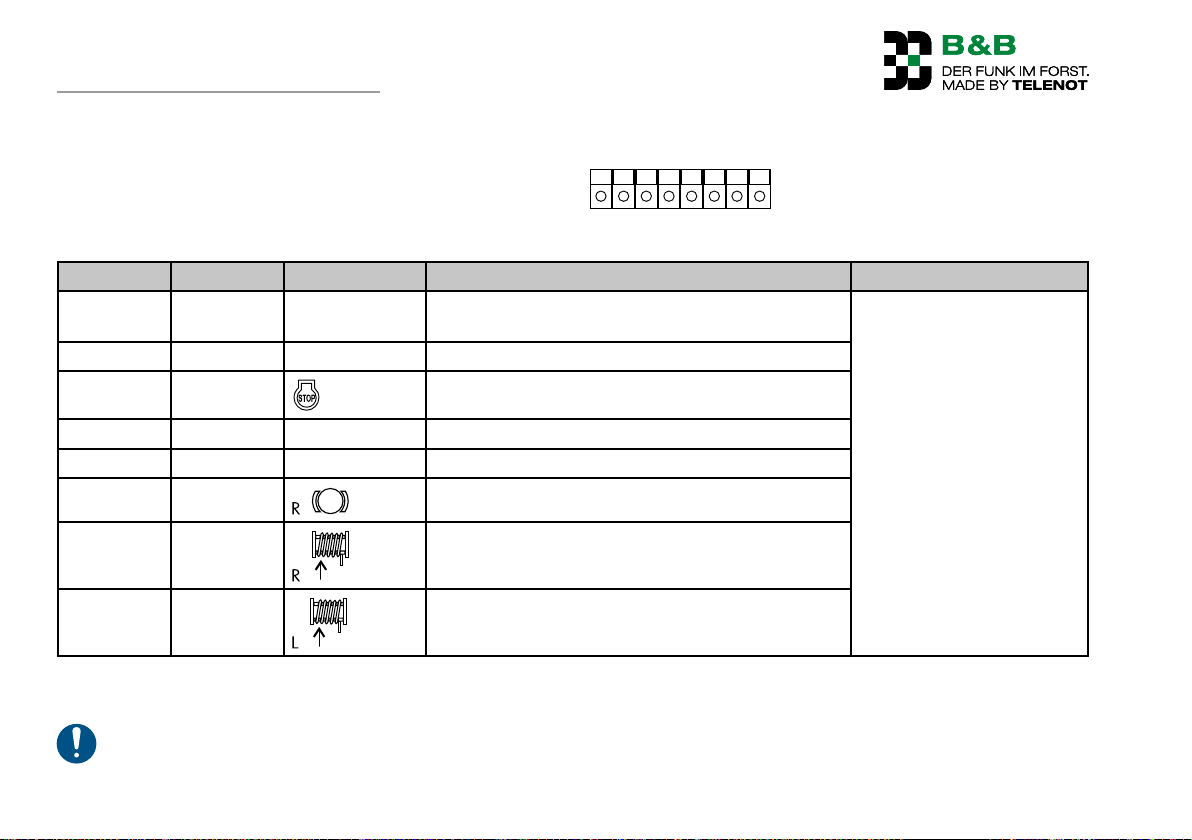
1 2 3 4 5 6 7 8
12.3 Connection configuration
12.3.1 Socket 1
The connections of sockets 1 and 2 are already prewired at the
factory to one or several vehicle connectors. The assignment is
based on the winch type and is attached to the remote control.
Socket 1 connection configuration
Pin Type Labeling / icon Function Technical Data
1 Output NOT In the event of emergency off to trigger a loud horn /
Switches +U
private mobile radio device
2 Output P Optional EMERGENCY potential-free
3 Output
Not occupied
4 Output B Not occupied
5 Output SIR Siren (pre-alarm, main alarm)
6 Output
7 Output
8 Output
Table: Socket 1 connection configuration
Not occupied
Not occupied
Pull drum
/ max. 5A
B
Do not apply any voltage to the outputs!
30
Page 31
Connections and Interfaces
1 2 3 4 5 6 7 8
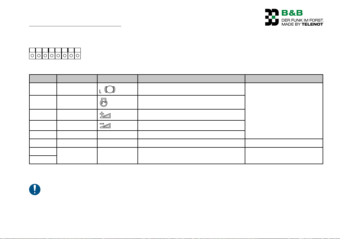
12.3.2 Socket 2
Socket 2 connection configuration
Pin Type Labeling / icon Function Technical Data
1 Output
Release brake Switches +UB / max. 5A
2 Output
3 Output
4 Output
5 Output C Not occupied
6 Power GND Ground / 0 V 0V / max.5A
7 Power +U
8
Table: Socket 2 connection configuration
B
Do not apply any voltage to the outputs!
Not occupied
Gas+
Gas–
+UB (operating voltage) +10V bis +30VDC/max. 15A
31
Page 32

Installation
13 Installation
The connection line for the radio control F6 is pre-wired at the
factory for one or more plugs (e. g. 7-pin vehicle plugs). The
configuration and plug type dependend on the winch type.
For the following winch types there are pre-assembled connection
cables:
AMR/BGU/Uniforest
Farmi
Fransgård
GVS
Holzknecht
Igland
KMB
Königswieser
Krpan/Oehler
Maxwald
Pfanzelt
Ritter (old)
Ritter KWF
Schlang & Reichart
Tajfun
Werner/Glogger
DANGER!
Danger due to malfunctions as a result of incorrect
cabling
The receiver may only be connected by a specialist
according to the pin assignment diagram enclosed.
A radio control with the "Gas +/-" and/or "MotorStart/
MotorSTOP" functions must use a separate connection
box. Reason: If the radio control is inserted into the
"Trailer lighting" socket, this will cause a short circuit.
32
Page 33
Wiring diagrams
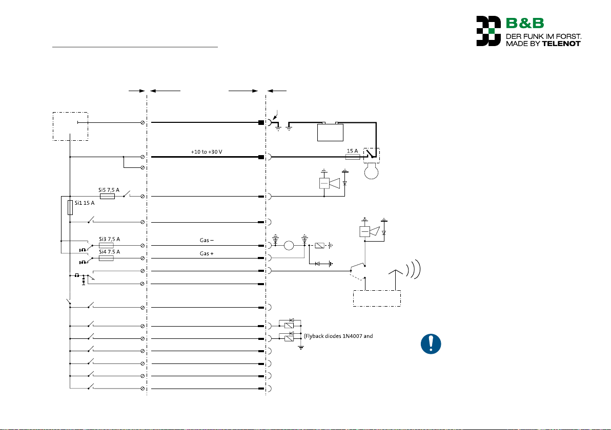
Receiver Connection cable
Winch / vehicle
14 Wiring diagrams
Electronics
14
15
16
K6
5
Ground / 0 V
Siren (pre-alarm)
Earth connection on vehicle chassis, used separately
and not simultaneously by other consumers
Pre-alarm (alarm
device)
-
Battery
+
K11
BR2
BR5
BR4
BR3
K5
K10
K9
K1
K12
K4
K8
K7
K3
K13
K2
3
12
11
1
2
10
8
9
7
6
13
4
Wiring plan for the F6 E receiver
not occupied
NOT
P
not occupied
Pull drum
Release brake
not occupied
not occupied
not occupied
not occupied
M
Motor for gas
adjustment
Lift magnet
Solenoid valves
similar)
Loud horn
Private mobile radio device
To protect the receiver relay
contacts from sticking, inductive
consumers must be provided with
a flyback diode (e.g. 1N4007).
33
Page 34
Parameterization
15 Parameterization
15.1 Who performs the parameterization?
Nearly all functions are already parametrized at the factory.
Additional options are also parametrized at the factory.
Functions indicated with this icon can be parametrized.
Please refer to your dealer concerning this matter.
16 Commissioning
16.1 Requirements
The correct cabling of the receiver to the winch or to the
vehicle has been performed by a specialist according to the
relevant pin assignment diagram.
The batteries in the transmitter are full, or the rechargeable
batteries are charged.
16.2 Preparation
16.2.1 Receiver connection
Insert the connection plug(s) of the receiver into the
socket(s) provided on the winch / the vehicle.
DANGER!
Danger from incorrectly connected control unit
Do not insert the connection plug of the receiver into an
incorrect socket (e.g. vehicle socket for trailers). If two
separate connection sockets for connecting the manual
control and the radio control are located on the winch,
only one control unit may be connected at any one time.
When using the radio control, ensure that the manual
control cable is pulled out.
34
Page 35
Parameterization
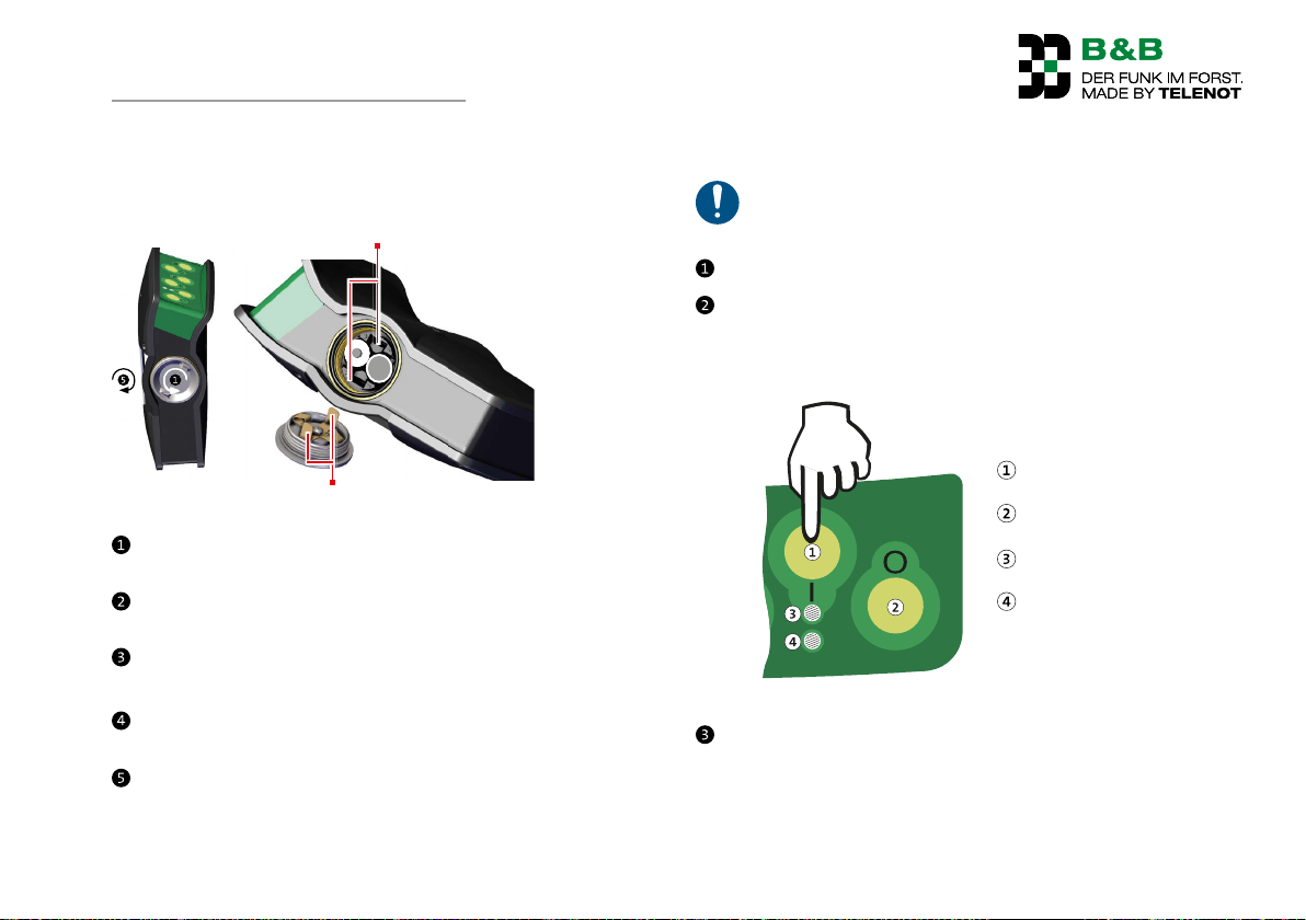
16.3.1 Fitting batteries/rechargeable batteries in the transmitter
Groove for guide tab
Guide tab
Turn the screw cover on the battery and rechargeable battery
compartment counterclockwise and pull off the lock.
Insert the left battery/ the left rechargeable battery, observing the correct polarity (negative pole points upwards).
Insert the right battery/ the right rechargeable battery, observing the correct polarity (negative pole points upwards).
Feed the guide tabs of the screw cap (positioned to be
rotated) into the grooves of the transmitter housing.
Tighten the screw cover on the battery and rechargeable
battery compartment by turning it clockwise, pressing it
firmly onto the compartment at the same time.
16.3 Functional test
NOTICE!
Generally perform the following points prior to
commencing work!
Switch the vehicle ignition on and start the vehicle.
Use the On button to switch on the transmitter.
The diagnostics LED on the receiver blinks green.
The status LED on the transmitter flashes green (if battery
full/ rechargeable battery charged).
1 s
On button
Off button
Status LED
Operating level LED
Switching on the transmitter F6 S
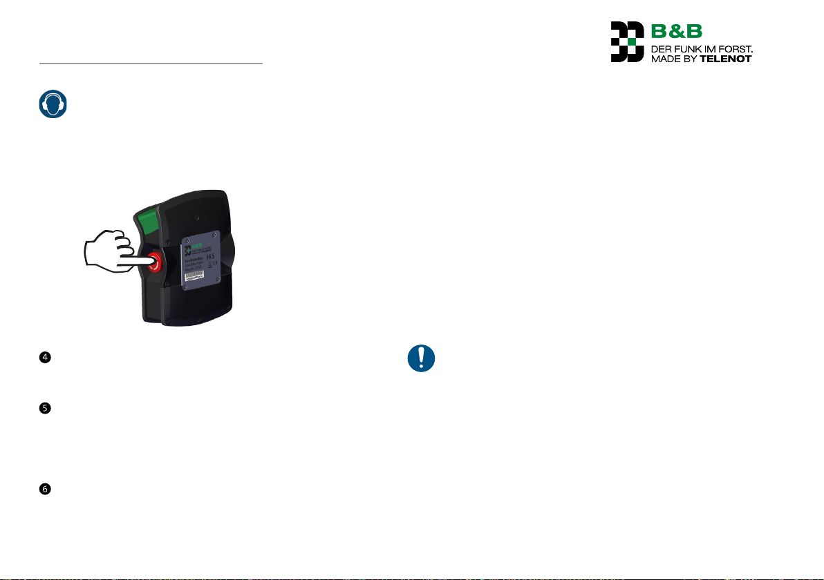
Press the stop and emergency call switch.
First, the pre-alarm (2 s tone, 2 s silence) and the main
alarm after 60 seconds (1 s tone, 1 s silence) by the siren.
The status LED on the transmitter blinks rapidly (green) (if
battery full/ rechargeable battery charged).
35
Page 36
Parameterization
CAUTION!
Hearing damage due to noise!
Wear hearing protection when you are working in the
direct vicinity of audible warning messages (> 85 dBA).
Remain in the vicinity of audible warning devices only
for as long as required.
Press stop and emergency switch
Perform any command on the transmitter (e.g. "Pull drum").
No dangerous work commands are performed and the siren
continues to sound.
Unlock the stop and emergency call switch by turning it
clockwise and switch the transmitter off using the Off button
and on again using the On button.
The siren is muted and the "Emergency" output switches
itself off again (only with main alarm).
Perform any command on the transmitter (e.g. "Pull drum").
The corresponding command is performed.
16.4 Fault-free operation
Requirements
Electrically sound connections within the entire system
Electrically sound ground and 0 V connections (frequent
fault sources are corroded contacts or inadequate ground
connections.)
The ground connection must be on a line that is separated
from other users (protect ground connections to appropriate
bodywork points from corrosion with protective lacquer).
Contact points may not be dirty, oxidized, or even rusty.
Cable, terminal, or plug connections may not be loose.
Fuse holders may not have any loose contacts.
Switches on the machine must not have any loose contacts.
Solenoid valves or the motor for gas adjustment must be
equipped with a diode protection circuit (flyback diode).
Check whether the diagnostics LED on the receiver begins
to flicker or goes off in an operating state. In this instance
there is a poor contact in the supply voltage of the receiver.
In this case, have the cabling checked by a specialist
workshop.
36
Page 37
Parameterization
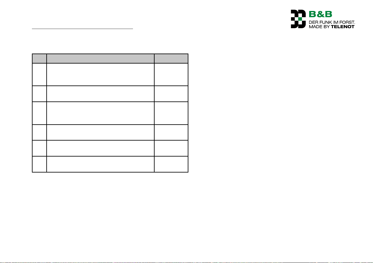
16.4.1 Commissioning check list
No. Activity Carried out
1 Cabling between receiver and winch has
been properly installed by a specialist
workshop
2 Receiver is inserted into the correct
socket(s)
3 Batteries in the transmitter are full, and
rechargeable batteries are charged
(see operation/transmitter/status LED)
4 Receiver is ready for operation
(see operation/receiver F6E)
5 Transmitter is switched on
(See operation / transmitter / status LED)
6 Function check has been performed
(See commissioning / function check)
37
Page 38
Operation
17 Operation
16.5 Safety notices for operation
DANGER!
Danger from vehicles tipping over
Ensure that the required stability of the vehicle is provided.
Check the ground.
DANGER!
Danger from pulling up tree trunks
Do not touch the towing cable during operation!
Nobody should be located around the intake zone of the
cable winch!
DANGER!
Danger from tree trunks falling down
Keep a safe distance from the cable winch.
DANGER!
Danger from unintentional triggering of functions or
starting up
Ensure that no unintended actuation of the transmitter
can be caused by items of clothing and similar items.
Switch the transmitter off during break times and at the
end of work and secure it against unauthorized access
(e.g. from children).
Make sure that the receiver is unplugged while driving.
DANGER!
Danger from cutting off and restoration of the power
supply for the transmitter/receiver
Nobody should be located around the intake zone of the
cable winch!
Keep a safe distance from the cable winch.
38
Page 39

Operation
Requirements for safe operation
Wear protective work clothing suitable for the activity and
the deployment location (PPA).
Before switching on the radio control, ensure that nobody
could be put at risk from operation.
Always work with a direct line of sight to the machine and
proceed with particular caution if you are not yet familiar
with operating the radio control.
Ensure that you do not accidentally mix up the cable move-
ment directions when changing locations or confuse the two
sides with double-drum winches.
To ensure that a work phase ends and consequently safe
conditions can be established on site in the highly unlikely
event of total failure of the battery, it is recommended that
you always carry two spare batteries and the manual control
for the winch with you in the vehicle.
The stop and emergency call switch on the transmitter
only affects the winch and is not to be confused with the
machine's emergency-off.
All non-observance of the safety information may result in
serious accidents and injuries.
In addition to generally applicable regulations for accident
prevention, the local regulations should also be observed.
Follow the instructions in the section "Maintenance".
Only use the radio control within the climatic, environmental
conditions that are specified in the section "Technical data".
Check whether the waist or chest belt is damaged each time
before starting work to prevent the loss of the transmitter.
39
Page 40
Operation
17.1 Receiver F6 E
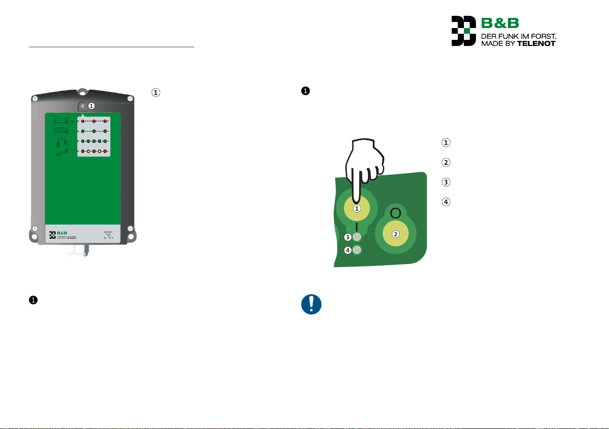
Diagnostics LED
Switching on the receiver F6 E
Switch the vehicle ignition on and start the vehicle.
Diagnostics LED on the receiver flashes red.
17.2 Transmitter F6 S
Use the On button to switch on the transmitter.
The diagnostics LED on the receiver blinks green.
The status LED on the transmitter flashes green (if battery
full/ rechargeable battery charged).
On button
1 s
Off button
Status LED
Operating level LED
Switching on the transmitter F6 S
To extend operating times and to avoid accidental
operating errors, always switch off the transmitter
during work breaks and after you finish work. Secure the
transmitter against unauthorized access. The transmitter switches off automatically after the parameterized
stand-by time (factory setting 20 minutes) if no command has been triggered.
40
Page 41
Operation
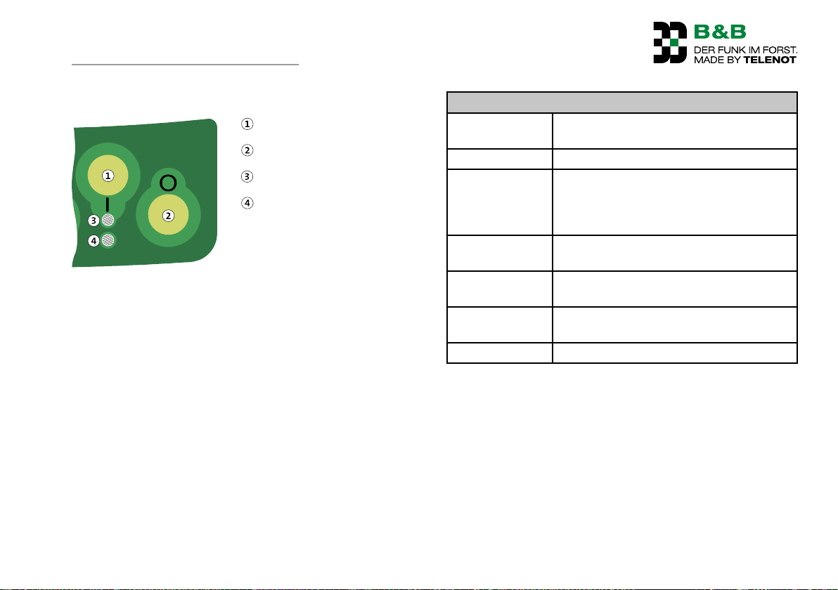
17.2.1 LED indications on the transmitter F6 S
On button
Off button
Status LED
Operating level LED
LED indications on the transmitter F6 S
Status LED
Flashes green Battery is charged; transmitter is ready for
operation
Blinks green Command is transmitted
Blinks quickly Stop switch on the transmitter actuated if
no other command is triggered. The green/
red color depends on the battery charge
level.
Flashes red Battery is almost empty; transmitter is
ready for operation
Blinks red Battery is almost empty; command is
transmitted
Illuminated
green
Battery is charged (shortly after switching
on the transmitter)
Illuminated red Battery is almost empty
41
Page 42
Operation
Important operating procedures are explained in the sections
that follow.
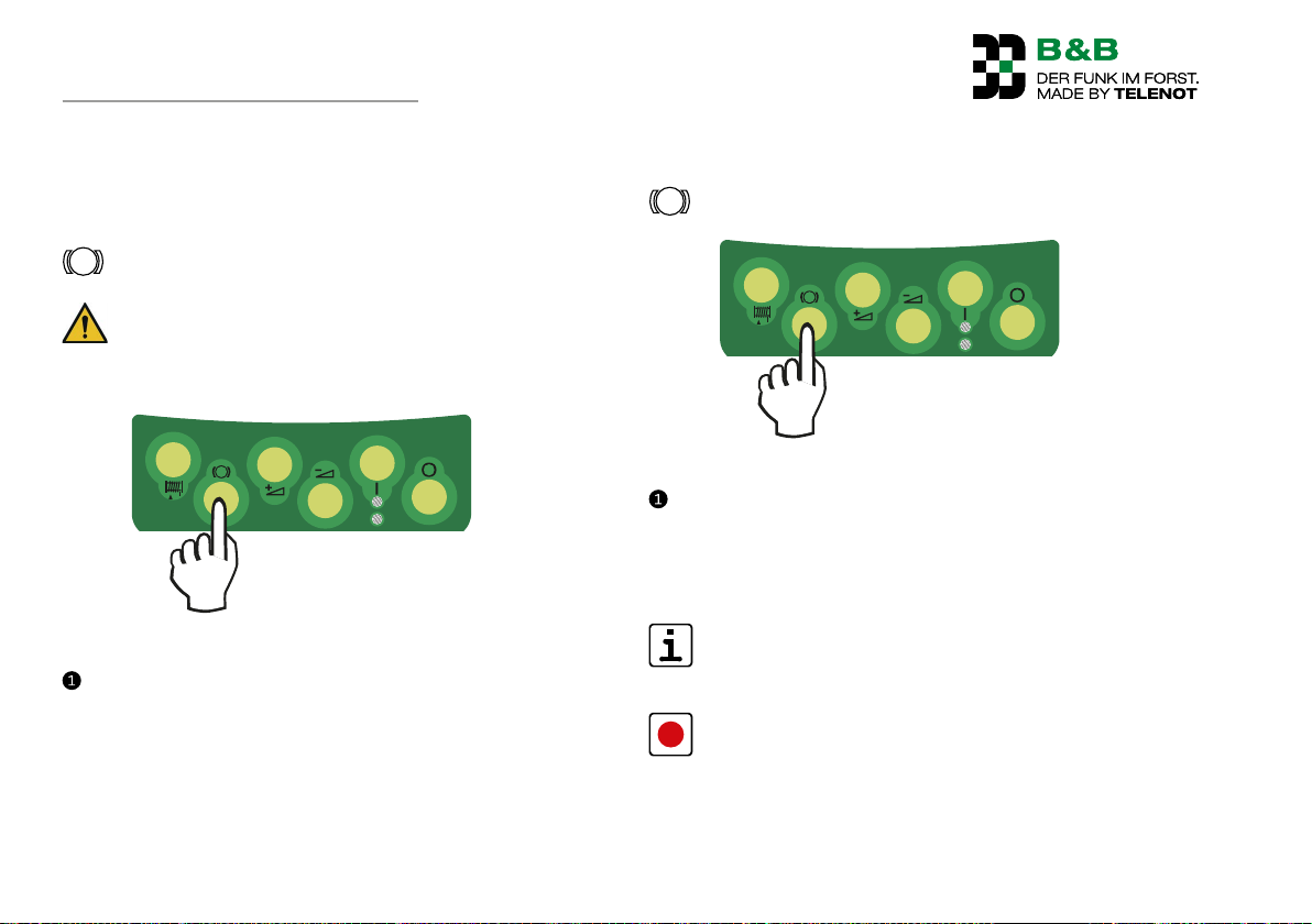
17.2.2 Release brake
WARNING!
Danger from falling load
Ensure that nobody is near the load to be lowered.
1 s
Release brake command
Press the button briefly ( 1.5 s). The brake is released as long
as the button is pressed and is applied again immediately
when the button is released (jog mode).
17.2.3 Permanent release
Via function "Release brake"
Release brake command
Press and hold the button for longer than 1.5 seconds or
3.5 seconds (pre-parameterized, depending on the winch
type).
The brake remains permanently released until "Release
brake" or "Pull drum" is pressed.
If the transmitter is not operated during the parameterized stand-by time (factory setting 20 minutes), it switches off automatically and the brake is applied.
If the function "Release brake without permanent release"
is parameterized at the factory, then "Permanent release"
cannot be realized.
42
Details: See function description / functions / release brake
Page 43
Operation
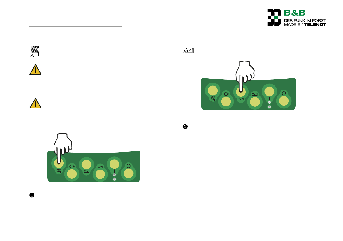
17.2.4 Pull drum
DANGER!
Danger from vehicles tipping over
Ensure that the required stability of the vehicle is
provided. Check the ground.
DANGER!
Danger from pulling up tree trunks
Do not touch the towing cable during operation!
Nobody should be located around the intake zone of the
cable winch!
1 s
Pull drum command
Press the button briefly. The cable intake continues as long
as the button is pressed and stops again immediately when
the button is released (jog mode).
Details: See function description / functions / Pull drum
17.2.5 Gas+
1 s
Gas + command
Press the button briefly. The motor speed increases while
the button is pressed. The set speed is maintained when
you release the button (jog mode).
Details: See function description / functions / gas adjustment
43
Page 44
Operation
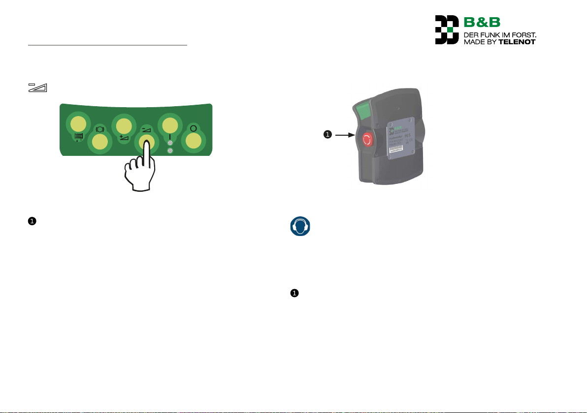
17.2.6 Gas–
1 s
Gas – command
Press the button briefly. The motor speed reduces while the
button is pressed. The set speed is maintained when you
release the button (jog mode).
Details: See function description / functions / gas adjustment
17.2.7 Triggering "Activeemergency"
Active emergency command
CAUTION!
Hearing damage due to noise!
Wear hearing protection when you are working in the
direct vicinity of audible warning messages (> 85 dBA).
Remain in the vicinity of audible warning devices only
for as long as required.
Press the stop and emergency call switch until it locks into
place.
44
Page 45

Operation
Active emergency is triggered, the green status LED blinks
quickly (the color green / red depends on the battery charge
status)
Activated commands are switched off immediately and
other dangerous commands (e.g. "Pull drum") are blocked
(command lock).
When the "Siren" output is activated, the audible pre-alarm
phase simultaneously begins (2 s sound, 2 s pause, etc.).
After a period of time parameterizable at the factory (factory
setting: 30 secs) the "Emergency" output is activated and the
main alarm is tripped (siren: 1 sec sound, 1 sec pause, etc.).
The stop and emergency call switch remains functional even
when the transmitter is switched off. By actuating the stop
and emergency call switch the transmitter can be switched
back on. If the stop and emergency call switch is pressed, the
transmitter cannot be switched off again.
WARNING!
Danger from vehicle functions that are not triggered by
the remote control.
The stopping of the winch by pressing the stop and
emergency call switch has nothing to do with the
"Emergency off" of the machine. In the event of emergencies, ensure that the "Emergency off" of the machine
is pressed separately.
Details: See function description / functions / function active
emergency call ("active emergency")
45
Page 46
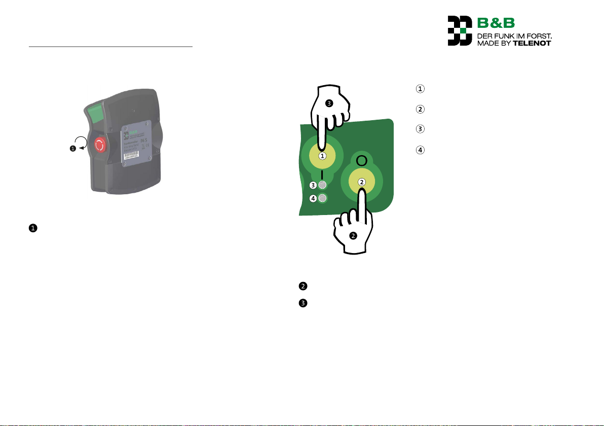
Operation
17.2.8 Reset "Active emergency"
Reset "Active emergency" command
Turn the stop and emergency call switch in a clockwise
direction until the switch is released and returns to its
resting position.
The command lock is lifted and the system is functional
again. The alarm continues.
Reset "Alarm"
On button
1 s
Off button
Status LED
Operating level LED
1 s
Reset alarm after "Active emergency"
Switch off the transmitter by pressing the Off button.
Switch the transmitter on again by pressing the On button.
The siren and the output "Emergency" (for main alarm only)
are switched off and the alarm is reset.
46
Page 47
Operation
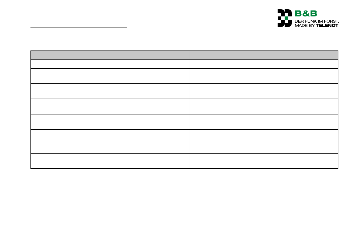
17.3 Eliminate fault states
No. Fault Solution
1 Diagnostics LED on the receiver is off Check the reciever and voltage supply
2 Diagnostics LED on the receiver flashes red Switch on transmitter / bring transmitter within the
receiver's range
3 Diagnostics LED on the receiver flashes alternately, red /
orange (siren monitoring has tripped)
4 Diagnostics LED on the receiver flashes alternately, two
times red / two times orange (relay monitoring has tripped)
5 Diagnostics LED on the receiver flashes alternately, three
times red / three times orange (device malfunction)
6 Status LED on the transmitter is off Switch on transmitter / check the battery
7 Status LED on the transmitter flashes red (battery almost
empty)
8 Operating level LED flashes red (no radio response received
by receiver)
Check fuse 5 and supply cable for the siren
Check fuse 1 and relay outputs for short circuits (no voltage
may be applied if the output is inactive)
Contact service
Charge the battery
Check whether the receiver is switched on (diagnostics LED) /
bring the transmitter within the receiver's range.
47
Page 48
Maintenance and service
18 Maintenance and service
18.1 Recommended maintenance interval
Carry out maintenance work at least once annually.
18.2 Scope of maintenance
Have all the electrical cabling on your vehicle, and the
electrical, remote-controlled appliances connected to it,
checked regularly by a specialist to ensure it is in perfect
condition.
Check the connection cable and, if available, the antenna
cable for bare or frayed spots.
Before each time maintenance work is performed, you must
turn off the ignition on the vehicle and take out all the
plugs of the radio control unit to ensure that no function is
triggered involuntarily.
If you discover a fault:
DANGER!
Danger due to malfunctions
Work can no longer be performed with a defective system.
Send back the whole system for repair in appropriate
packaging with the transmitter and receiver, including
the connection cables and a precise description of the
problem. A corresponding response form is available for
download on our website at http://www.funk-im-forst.de/
service.
NOTICE!
Risk of damage to the device from welding on the
vehicle
Before electric welding work on the log-moving vehicle,
the winch connection cable plug is to be pulled out of
the winch socket in order to prevent damage to the
receiver electronics.
48
Page 49
Maintenance and service
18.2.1 Cleaning the transmitter and receiver
Before cleaning you must turn off the ignition on the vehicle
and take out all the plugs of the radio control unit so that no
function is triggered involuntarily. Clean the system parts with a
damp or soaked in spirits cloth.
NOTICE!
Risk of damage to the device from cleaning the vehicle
Prevent system parts having direct contact with oils or
lubricants. The system parts may not be cleaned with a
steam-jet degreaser / high-pressure washer.
18.2.2 Batteries
If the status LED on the transmitter goes out shortly after you
switch on the transmitter, you must replace the batteries (see
Commissioning/Preparation/Fitting Batteries/Rechargeable
Batteries in the Transmitter)
18.2.3 Rechargeable batteries (optional)
To prevent a deep discharge the transmitter automatically switches itself off when there is very low battery voltage (passive
emergency = off).
Charge the batteries regularly.
If the status LED of the transmitter goes out just a short time
after the transmitter is switched on, the batteries must be
replaced (see commissioning / preparation / installing the transmitter batteries).
In the event of an emergency, a work process that has
begun can be ended by switching on the transmitter
again.
49
Page 50
Maintenance and service
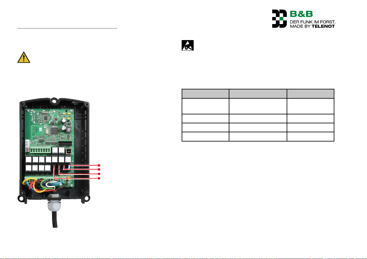
18.2.4 Changing fuses in the receiver F6 E
NOTICE!
Risk of damage to the device from opening the receiver
housing
The receiver may only be opened by qualified specialist
personnel. In general do not interfere with the device as
this will invalidate the warranty.
K12 K13
K5 K6 K7 K8 K9 K10 K11
K1 K2 K3 K4
Si 1
Si 5
Si 4
Si 3
NOTICE!
Risk of damage to device due to electrostatic charge
Discharge yourself by touching grounded metal parts.
This procedure prevents damage to semiconductors by
electrostatic discharge (ESD).
Fuses
fuse Meaning Figure
Si1 Main fuse
15A
(relay outputs)
Si3 Gas+ 7.5A
Si4 Gas– 7.5A
Si5 Siren 7.5A
All fuses: Vehicle mini-plug fuse (mini fuse)
Position of fuses and relays in the receiver F6 E
50
Page 51
Maintenance and service
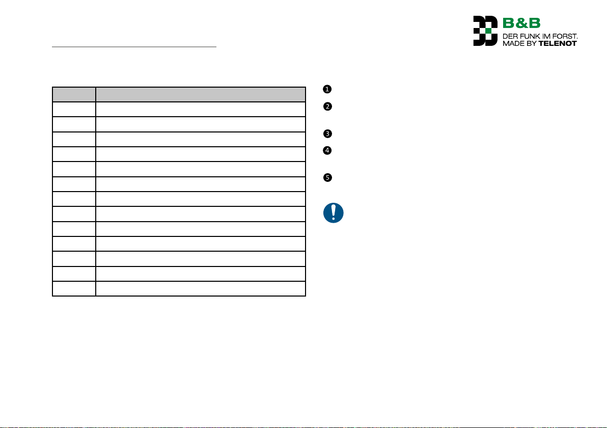
Relay
Relay Meaning
K1 Emergency
K2 Not occupied
K3 Not occupied
K4 Pull drum
K5 Not occupied
K6 Siren
K7 Not occupied
K8 Release brake, permanent release, cable output
K9 Gas+
K10 Gas–
K11 Unlock +UB
K12 Not occupied
K13 Not occupied
Table: Relay key
Procedure for the qualified specialist
Pull the connection cable(s) from the winch/vehicle socket.
Localize the source of the fault and eliminate it; e.g. short
circuit in the cabling.
Remove the 4 housing screws and open the housing lid.
Only replace defective fuses with fuses of the same type
(same value!).
Put on the housing cover and screw the 4 housing bolts on
tightly.
In general do not interfere with the device anymore, as
this will invalidate the warranty.
51
Page 52

Disassembly and disposal
19 Disassembly and disposal
19.1 Decommissioning
At the end of the device's service life you must disassemble the
device and dispose of it in an environmentally acceptable manner.
You must put the device out of operation before you disassemble
it.
Switch off receiver and unplug from the winch/vehicle socket
Switch off transmitter and remove batteries
19.2 Disassembling the receiver F6 E
If available: Disassemble the remote antenna.
Remove the 3 fixing screws of the receiver housing.
19.3 Disposal
Scrap metal
Hand in synthetic elements for recycling
Recycle electrical and electronic parts, or return them to
TELENOT.
The product is subject to the valid EU WEEE Directive
(Waste Electrical and Electronic Equipment). As the owner of this product, you are obliged by law to dispose of
waste equipment at a recycling plant, separately from
the domestic waste. Please observe the country-specific
instructions for disposal.
In accordance with the battery ordinance, batteries must
not be disposed of with domestic waste! You can return
NiMH
batteries purchased from TELENOT free of charge, where
they are disposed of properly.
52
Page 53
Technical Data
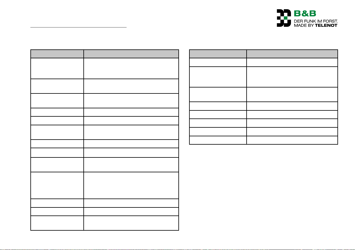
20 Technical Data
Feature Figure
Frequency range 70-cm ISM band,
3 radio channels (434.175MHz/
434.475MHz/ 434.675 MHz)
System address Unique address for transmitter and recei-
ver (approx. 16 million)
Control commands 4 control commands, additional 1 ×
emergency and 1 × siren (horn)
Modulation GMSK
Receiver category 2
Max. emitted transmission power
Hamming distance D=6
Operation mode Half duplex
Operating temperature
Storage temperature -20°C to +30°C (The self-discharge effect
Humidity Storage at max. 40% in operation 100%
Protection class IP65
Performance Level
(risk assessment)
< 10 mW
–20°C to +60°C
of the batteries/rechargeable batteries is
temperature-dependent and increases at
higher storage temperatures.)
ISO13849-1:2006 class 1PLc
Transmitter
Feature Figure
Range Several hundred meters in a free field
Power supply 2 AA batteries (optional 2 eneloop®
AA rechargeable batteries 1.2V DC/
1900mAh)
Operating time 50 hours continuous transmission with
a battery charger
Antenna Integrated
Dimensions (WxHxD) (116×161×61)mm
Color Black, operating panel green/yellow
Material Polyamide / 66 – GF + TPE
Weight Approx. 600 g with battery
53
Page 54
Technical Data
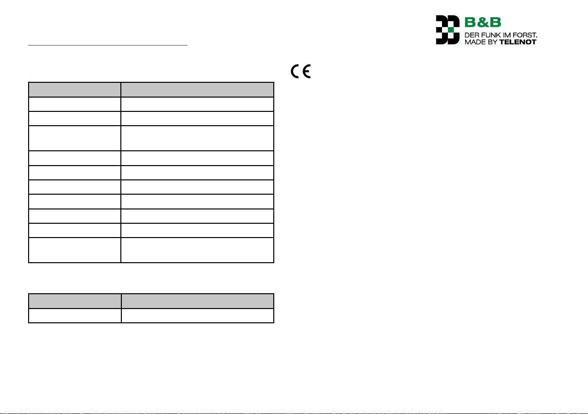
Receiver
Feature Figure
Operating voltage +10V to +30V DC
Power consumption 20 to 400mA
Outputs Output relay secured, response time
<200ms
Diagnostics LED Displays operating states and faults.
Antenna integrated
Dimensions (WxHxD) 152×218×51 mm
Color Black
Material PC/ABS
Weight Approx. 670g
Connection cable,
length
Rechargeable battery charger A-LG 230 V (optional)
Feature Figure
Operating voltage 230VAC/50Hz/5W
2.7m
This symbol confirms that the devices comply with the
machinery directive 2006/42/EC, the radio equipment
directive (RED) 2014/53/EU and the protection targets
of low voltage directive 2014/35/EU and EMC directive
2014/30/EU.
The system is free of charge and does not need to be registered
with the Federal Network Agency (BNetzA). The F6 radio control
may be operated with the specified operating frequencies in the
following countries: Albania, Andorra, Austria, Belgium, Bosnia
and Herzegovina, Belarus, Bulgaria, Republic of Cyprus, Czech
Republic, Germany, Denmark, Spain, Estonia, France, Finland,
United Kingdom of Great Britain and Northern Ireland, Greece,
Hungary, The Netherlands, Croatia, Italy, Ireland, Iceland, Principality of Liechtenstein, Lithuania, Luxembourg, Latvia, Moldova,
Macedonia, Malta, Montenegro, Norway, Poland, Portugal,
Romania, Sweden, Serbia, Switzerland, Slovakia, Slovenia, Turkey.
54
Page 55
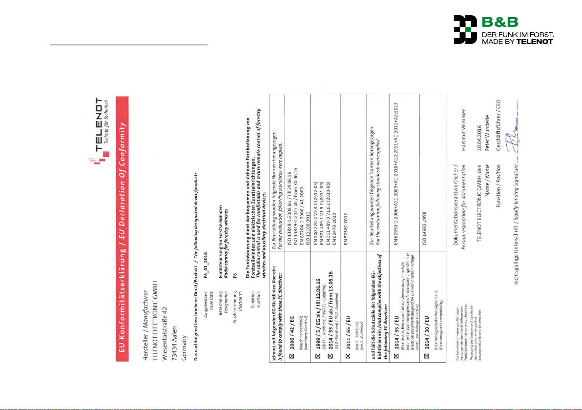
Declaration of conformity
21 Declaration of conformity
EC Declaration of Conformity F6
55
Page 56
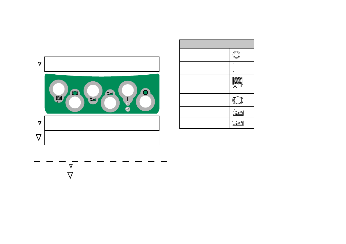
F6 wireless control
Transmitter operation (basic functions)
Pull
Permanent release
Legend Short operation
Increase motor
Release
Long operation
speed
Reduce motor speed
on
off
Symbol overview
Transmitter off
Transmitter on
Pull drum
Release brake
Gas+
Gas–
Subject to technical modifications
110061579 (02)
 Loading...