

Page 1

T-LightTM LCU (Light Control Unit) NEMA LoRa
User Manual
Models: LCUN2LUS and LCUN2LEU
Revision 1.0, September 12, 2019
Copyright © Telematics Wireless Ltd.
All rights reserved
The document contains proprietary information of
containing restrictions on use and disclosure, and is also protected by copyright law.
Due to continued product development this information may change without notice. The information and intellectual property
contained herein is confidential between
Telematics Wireless Ltd. If you find any problems in the documentation, please report them to us in writing. Telematics
Wireless Ltd.
No part of this publication may be reproduced, stored in a retrieval system, or transmitted in any form or by any means,
electronic, mechanical, photocopying, recording, or otherwise without the prior written permission of Telematics Wireless
Ltd.
does not warrant that this document is error-free.
Telematics Wireless Ltd. and the client, and remains the exclusive property of
Telematics Wireless, Ltd.; it is provided under a license agreement
Page 2

Content
About Telematics Wireless Products ................................................................................................... 3
Description ........................................................................................................................................ 3
Smart Lighting System Overview ........................................................................................................ 4
LCU NEMA LoRa ................................................................................................................................. 5
Standard Features .................................................................................................................................... 5
“Auto Detection and Verification” Software ............................................................................................ 5
Optional Features ..................................................................................................................................... 5
LCU LoRa Supported Data Transfer .......................................................................................................... 6
Technical Specifications ..................................................................................................................... 7
LoRa RF Radio Characteristics ................................................................................................................... 7
Environment ............................................................................................................................................. 7
LCU NEMA Dimensions ............................................................................................................................. 8
LCU NEMA Electrical Structure............................................................................................................ 9
LCU NEMA Contacts/Wiring ..................................................................................................................... 9
LCU NEMA Contact Details ..................................................................................................................... 10
LCU NEMA Pinout ................................................................................................................................... 10
Standards Compliance ...................................................................................................................... 11
LoRa Certification ................................................................................................................................... 11
Regulation Information .................................................................................................................... 12
FCC Part 15 Regulation Class B device .................................................................................................... 12
FCC interference Notice .......................................................................................................................... 13
FCC Radiation Hazard Warning ............................................................................................................... 13
Installation Requirements
Mandatory Customer-Supplied Equipment............................................................................................ 14
Mandatory Voltage Surge Protection ................................................................................................. 14
Mandatory Current Surge Protection ................................................................................................. 14
Location 14
Post-Installation Commissioning ............................................................................................................ 15
Contact Details ................................................................................................................................ 15
................................................................................................................ 14
2
Page 3

About Telematics Wireless Products
Telematics Wireless products have been evaluated as Information Technology Equipment (ITE), which
may be installed in Central Offices, Telecommunication Centers, offices, computer rooms, and similar
commercial type indoor or outdoor locations.
Telematics Wireless is an associate member of the TALQ Consortium, and its products are ELEXON
approved. The T-Light™ Wireless Light Control Unit (LCU) is also certified by Intertek.
Description
The T-Light™ Wireless Light Control Unit (LCU) and its communication interface with the T-Light
management software are key components in the Telematics Wireless Smart Lighting System. The LCU is
a wireless control unit installed in one of the following locations:
• On top of the luminaire fixture (External)
• In the luminaire fixture (Internal)
• In the base of the pole (Internal)
The LCU handles the collection and transmission of luminaire data and the execution of commands on the
luminaire from the Smart Lighting System Control Management Software (CMS).
3
Page 4
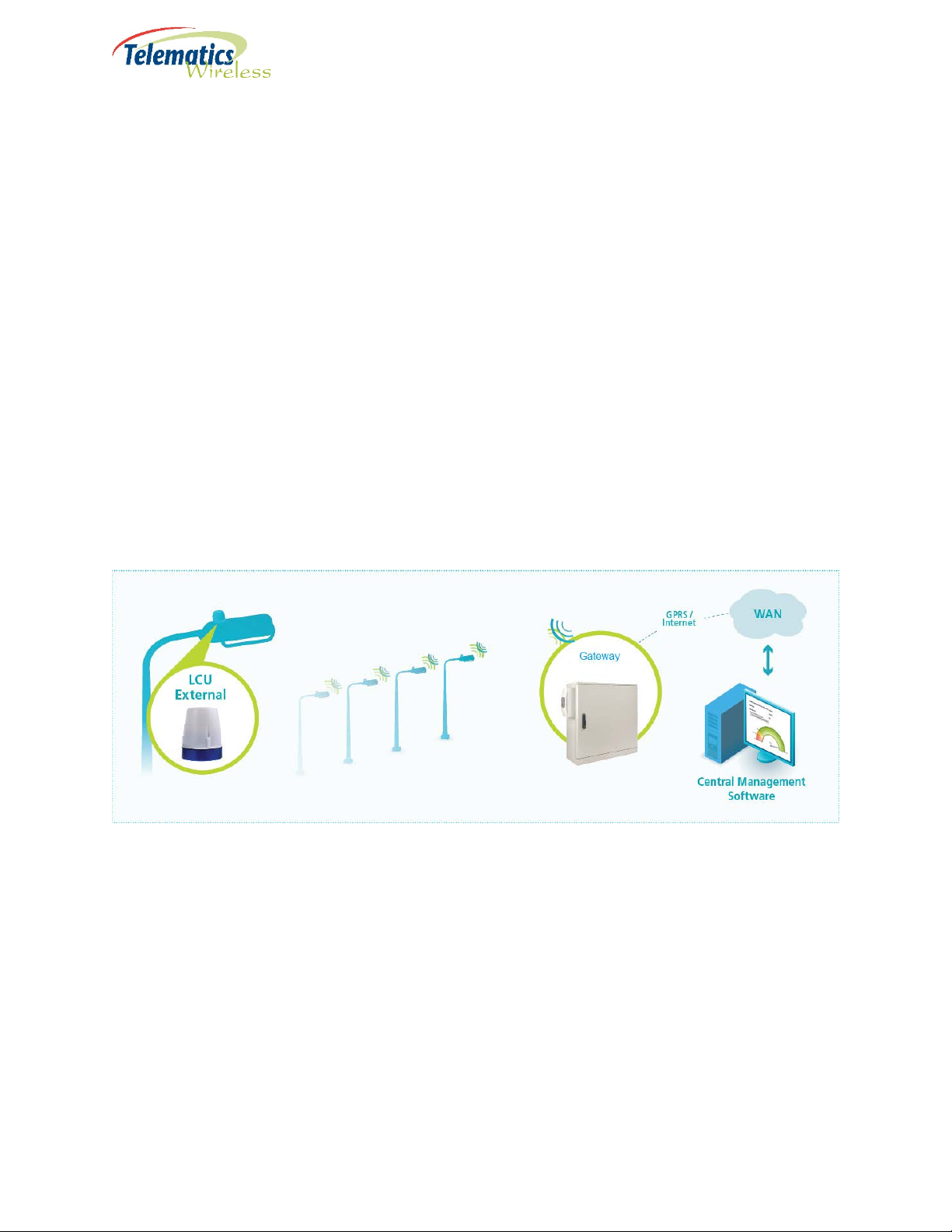
Smart Lighting System Overview
The Smart Lighting System collects data from and manages the operation of remote street luminaires. The
System consists of the following components:
• LCU – Located on top of or inside the luminaire cover, or in the light pole, the LCU sends sensor data
and executes scheduled and unscheduled luminaire control commands, such as on/off and dim,
received from the CMS Application Server.
• LoRa Gateway – the gateways forward message to/from Network Server to end devices.
• LoRa Network Server – forward message to appropriate Application Server and selects best gateway
to send message for transmission to end devices.
• CMS – Web-based backend application server provides real-time management: receives LCU
communications from the LoRa network server and sends luminaire control commands to the LoRa
network server for transmission to LCUs.
CMS usually contains a database of static and dynamic LCU information: ambient light values, lighting
and dimming schedules, power usage, status, etc.
Figure 1 – System Topology
4
Page 5

LCU NEMA LoRa
The LCU NEMA LoRa is an external luminaire control device that is installed on top of the luminaire cover
into a standard NEMA socket. Control features offer On/Off and dimming level operations. Monitoring
features include identification of lamp and electrical issues and measurement of electrical parameters.
The LCU NEMA uses standard NEMA socket “twist and lock” installation on top of a pole or luminaire
cover, according to ANSI C136.10 and C136.41 specifications.
Standard Features
• Light sensor - Operates as a photocell with the integrated microcontroller and is used as a backup light
control in the event of microcontroller failure.
• Energy meter - Continuous measurement collection and aggregation.
• Integrated RF antenna.
• Real Time Clock (only when connected to the system or when unit received its time zone from the
system and operates with GPS)
• Network data is protected by AES 128 encryption.
• Relay Control for LED driver/ballast power.
• Uses unlicensed frequency.
• Built in GPS receiver for auto-commissioning
• “Auto Detection and Verification” Software
“Auto Detection and Verification” Software
The LCU NEMA includes the Telematics “Auto Detection and Verification” software that automatically
detects and stores the ballast type (1-10V or DALI) in the LCU. The ballast type is then retrieved during the
commissioning process, thereby eliminating the need to enter it manually into the CMS (auto detection
process also occur each time the power turns on from off state)
Optional Features
• Built-in GPS receiver for full auto-commissioning.
5
Page 6

LCU LoRa Supported Data Transfer
With the proper matching of LED driver, the following data information will be provided.
• Current
• Voltage
• Lamp energy (kWh)
• Metered/Active power (Watt)
• Power Factor
• Lamp Burning hours
• LED Driver Temperature (depend on LED driver characteristics)
6
Page 7
Feature
Specification
Dimming – Ballast/Driver Communication Protocols
DALI
Operating Input Voltage
110-277V AC @50-60Hz
Load Current
10A
Internal Surge Protection
350J (10kA)
MTBF
>1M hours
Isolation
3.75kVac/5mA/5Sec
Power Consumption
Up to 2W
Parameter
Value
Unit
Operating Frequency:
KR920
920-923
MHz
Network Topology
Star of Starts
Modulation
KR920
LoRa125
Maximum Transmitter output power
KR920
Up to 14 (EIRP)
dBm
Antenna Gain (Typical)
0
dBi
Antenna Type
built in Antenna
-40° F to 161.6° F
IP Rating
IP 66 per IEC 60529-1
Technical Specifications
(different configurations depend on part number
ordering information)
LoRa RF Radio Characteristics
EU868
US915
AS923
EU868
US915
AS923
Analog 0-10V
863-870
902-928
920-925
LoRa125, LoRa250, FSK
LoRa125, LoRa500
LoRa125, LoRa250, FSK
MHz
MHz
MHz
EU868
US915
AS923
(1)
The RF characteristics are derived from LoRa
Environment
Operating Temperature
7
Up to 16 (EIRP)
Up to 21 (conducted)
Up to 16 (EIRP)
TM
specifications
(-40° C to +72° C)
dBm
dBm
dBm
Page 8
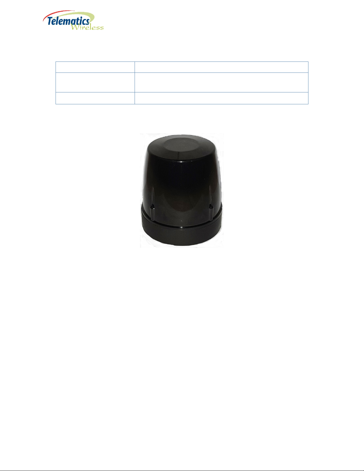
Model
Measurements
External – NEMA
3.467 in D x 4.173 in H
Weight
225 g
LCU NEMA Dimensions
(88 mm D x 106 mm H)
Figure 2 - LCU NEMA Enclosure
8
Page 9

LCU NEMA Electrical Structure
LCU NEMA Contacts/Wiring
Following is a wiring diagram for a NEMA receptacle with dimming pads for use with the LCU NEMA:
Figure 3 - NEMA Receptacle Wiring Diagram for use with LCU NEMA
Figure 4 - LCU NEMA 7-Pin Contact Interface
9
Page 10

#
Wire Color
Name
Purpose
1
Black
Li
AC Line In
2
White
N
AC Neutral
3
Red
Lo
AC Line Out: Load
4
Violet
Dim+
DALI(+) or (+)0-10V or PWM or RS485-A
5
Gray
Dim-
Common GND: DALI(-) or (-) 0-10V or RS485-B
6
Brown
Reserved 1
Digital IO or Analog In or RS485-A (optional)
7
Orange
Reserved 2
Digital IO or RS485-B (optional)
LED Driver
Model
Pin 1-2
Pins 3-2
Pins 5-4
Pins 6-7
External NEMA
Main AC Line IN
AC for lamp Line
Dimming – 0-10V
For future user
LCU NEMA Contact Details
LCU NEMA Pinout
7-pin
Black-White
Main AC Neutral IN
Red-White
OUT
Neutral IN
Gray-Violet
Analog, DALI, PWM,
Modbus RS485
Brown-Orange
purposes, for
example, sensors,
Modbus RS485,
GPIO-digital or
analog
10
Page 11
Region
Category
Standard
All
Quality Management
ISO 9001:2008
Locking Type
ANSI C136.41
IP Rating
IP 66 per IEC 60529-1
Europe
Safety
IEC 61347-2-11(IEC 61347-1)
EMC/Radio
ETSI EN 300220-1&2, ETSI EN 301489-1&3
United States
Safety
UL916
EMC/Radio
47CFR FCC Part 15
Standards Compliance
Systems
CSA C22.2#205
LoRa Certification
The LCU has LoRa Module certified with LoRa Alliance™.
11
Page 12

Regulation Information
FCC Part 15 Regulation Class B device
The digital circuit of this device has been tested and found to comply with the limits for a Class B
digital device, pursuant to part 15 of the FCC Rules. These limits are designed to provide
reasonable protection against harmful interference in a residential installation. This equipment
generates uses and can radiate radio frequency energy and, if not installed and used in accordance
with the instructions, may cause harmful interference to radio communications. However, there
is no guarantee that interference will not occur in a particular installation. If this equipment does
cause harmful interference to radio or television reception, which can be determined by turning
the equipment off and on, the user is encouraged to try to correct the interference by one or
more of the following measures:
-Reorient or relocate the receiving antenna.
-Increase the separation between the equipment and receiver.
-Connect the equipment into an outlet on a circuit different from that to which the receiver
is connected.
-Consult the dealer or an experienced radio/TV technician for help.
12
Page 13

FCC interference Notice
This device complies with part 15 of the FCC rules. Operation is subject to the following two
conditions:
(1) This device may not cause interference; and
(2) This device must accept any interference, including interference that may cause undesired
operation of the device.
FCC Radiation Hazard Warning
WARNING! To comply with FCC RF exposure compliance requirements, the device should
be located at a distance of at least 20 cm from all persons during normal operation. The
antennas used for this product must not be co-located or operated in conjunction with any
other antenna or transmitter.
WARNING! Changes or modifications to this equipment not expressly approved by the
party responsible for compliance (Telematics Wireless Ltd.) could void the user’s authority
to operate the equipment.
13
Page 14

Installation Requirements
Mandatory Customer-Supplied Equipment
System integrity for the LCU NEMA is ensured with the mandatory installation of customersupplied voltage and current surge protection equipment.
Mandatory Voltage Surge Protection
Warning: To prevent damage due to power network voltage surges, it is
mandatory that you also provide and install a surge protection device to protect
the LCU and the luminaire driver.
Mandatory Current Surge Protection
Warning: To prevent damage due to power network current surges, it is
mandatory that you also provide and install a 10 amp slow-blow fuse or circuit
breaker to protect the LCU and the luminaire driver.
Location
The LCU NEMA is installed on the top surface of the luminaire cover utilizing a standard (twist and
lock) NEMA socket.
14
Page 15

Post-Installation Commissioning
The serial numbers and GPS coordinates of the LCU NEMA units must be added to the CMS
Equipment Inventory as part of the commissioning process. The level of automation in the
Commissioning process depends on the optional equipment installed in the LCU NEMA:
• GPS – Commissioning is fully automated. Commissioning is complete after the CMS Administrator
executes the relevant command.
• No GPS – Commissioning is a partially manual process:
◦ Installer obtains the GPS coordinates of the LCU NEMA with a handheld GPS device.
◦ Installer records the serial number and GPS coordinates.
◦ CMS Administrator imports the recorded values into the CMS Equipment Inventory, one by
one or by batch.
Contact Details
Contact your local Telematics technical support representative, or contact us at:
Telematics Wireless, Ltd.
26 Hamelacha St., POB 1911
Holon 58117
ISRAEL
Phone: +972-3-557-5763
Fax: +972-3-557-5703
Sales: sales@tlmw.com
Support: support@tlmw.com
www.telematics-wireless.com
15
 Loading...